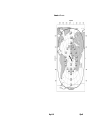
1
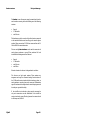
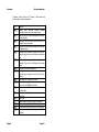
Capsat Messenger TT-3080A User Manual Thrane & Thrane Capsat Messenger TT-3080A User Manual Copyright Thrane & Thrane A/S ALL RIGHTS RESERVED Information in this document is subject to change without notice and does not represent a commitment on the part of Thrane & Thrane A/S. © 2000 Thrane & Thrane A/S. All rights reserved. Printed in Denmark. Document Number TT98—111882-E. Release Date: 8. June 2000 Safety Summary The following general safety precautions must be observed during all phases of operation, service and repair of this equipment. Failure to comply with these precautions or with specific warnings elsewhere in this manual violates safety standards of design, manufacture and intended use of the equipment. Thrane & Thrane A/S assumes no liability for the customers failure to comply with these requirements. GROUND THE EQUIPMENT To minimise shock hazard, the equipment chassis and cabinet must be connected to an electrical ground DO NOT OPERATE IN AN EXPLOSIVE ATMOSPHERE Do not operate the equipment in the presence of flammable gases or fumes. Operation of any electrical equipment in such an environment constitutes a definite safety hazard. KEEP AWAY FROM LIVE CIRCUITS Operating personnel must not remove equipment covers. Component replacement and internal adjustment must be made by qualified maintenance personnel. Do not replace components with the power cable connected. Under certain conditions, dangerous voltages may exist even with the power cable removed. To avoid injuries, always disconnect power and discharge circuits before touching them. DO NOT SERVICE OR ADJUST ALONE Do not attempt internal service or adjustments unless another person, capable of rendering first aid resuscitation, is present. DO NOT SUBSTITUTE PARTS OR MODIFY EQUIPMENT Because of the danger of introducing additional hazards, do not substitute parts or perform any unauthorized modification to the equipment. SAFETY DISTANCE FOR THE ANTENNA UNIT Minimum safety distance from the Antenna on the focal line is 1.8 m This page is intentionally left blank Table of Contents Table of Contents 1 Introduction.............................................................................. 1-1 2 Description of the service ........................................................ 2-1 3 The Capsat Messenger ............................................................ 3-1 3.1 Hardware interfaces ........................................................ 3-2 3.2 The handset ..................................................................... 3-5 3.3 SIMM card........................................................................ 3-9 3.4 PCMCIA card ................................................................. 3-10 3.5 Handling of the battery pack ......................................... 3-10 3.6 Charge indicator............................................................ 3-10 4 Getting started ......................................................................... 4-1 4.1 Select satellite.................................................................. 4-2 4.2 Pointing the antenna ........................................................ 4-3 4.2.1 Pointing the 3008A antenna ................................. 4-3 4.2.2 Pointing the 3008B Antenna................................. 4-9 4.3 NCS/LES connectivity .................................................... 4-11 5 Making calls ............................................................................. 5-1 5.1 Calling the terminal ......................................................... 5-1 5.2 Transferring incoming calls ............................................. 5-1 5.3 Call from handset............................................................. 5-2 5.4 Call from connected phone ............................................. 5-3 5.5 Call from connected fax................................................... 5-4 5.6 Call via RS-232 ................................................................. 5-5 5.7 Call via USB...................................................................... 5-6 6 Basic functions.......................................................................... 6-1 6.1 Top level menu ................................................................ 6-1 6.2 Phone Book ...................................................................... 6-2 6.3 Help Desk ........................................................................ 6-3 6.4 Call log ............................................................................ 6-4 6.5 Mailbox............................................................................ 6-5 6.6 Satellite setup .................................................................. 6-6 6.7 Phone setup ..................................................................... 6-8 13-Jun-00 Page i Table of Contents 6.8 6.7.1 Tel. numbers........................................................6-9 6.7.2 Route incoming..................................................6-11 6.7.3 Route outgoing ..................................................6-12 6.7.4 Security..............................................................6-13 6.7.5 Sleep mode........................................................6-16 6.7.6 MMI setup ..........................................................6-17 6.7.7 RS-232 parameters.............................................6-18 Status..............................................................................6-18 7 Advanced functions..................................................................7-1 8 Configuration Software.............................................................8-1 9 Technical Specifications ...........................................................9-1 9.1 Interfaces .........................................................................9-1 9.1.1 Antenna ...............................................................9-1 9.1.2 DC input...............................................................9-1 9.1.3 Handset interface.................................................9-2 9.1.4 Analog 2-wire interfaces......................................9-2 9.1.5 ISDN.....................................................................9-3 9.1.6 RS-232 interface ...................................................9-3 9.1.7 USB.......................................................................9-4 9.1.8 Audio input/output...............................................9-4 9.2 Specifications ...................................................................9-4 10 Azimuth and Elevation............................................................10-9 Page ii 13Jun00 Table of Contents This page is intentionally left blank 13-Jun-00 Page iii Hardware interfaces 1 Introduction Introduction Congratulations with your TT-3080A Capsat Messenger. This terminal makes it possible for you to communicate from any country in the world by utilising the Global Area Network service established by Inmarsat. This service supports high speed data (64 kbit/s circuit switched and packet data) and high quality voice as well as inexpensive voice, data and fax services. This manual has the following chapters. Chapter 2 Description of the service gives you an overview of the Global Area Network system and it’s services. Chapter 3 The Capsat Messenger gives a short description of the terminal and it’s capabilities to utilise the services of the Global Area Network. Chapter 4 Getting started and chapter 5 Making calls gives a quick step-by-step guide and describes about making and receiving phone calls, data calls and fax calls. Chapter 6 Basic functions describes in more detail the features which exist in the terminal. Chapter 7 Advanced functions gives an overview of the more advanced functions. Chapter 8 Configuration describes the basic features of the accompanying configuration PC software and how to set it up. Chapter 9 Technical Specifications contains detailed technical specification of ther terminal including electrical, mechanical and protocols supported. Please observ that not all features and all services are supported in every software version of the Capsat Messenger (for example the packet data service is not availble as service at the time of 13Jun00 Page 1-1 Introduction Hardware interfaces writing this manual). Please see seperate software release note’s which describe what is available in which software version. Page 1-2 13Jun00 Hardware interfaces 2 Description of the service Description of the service The Inmarsat Global Area Network service is based on 4 geostationary satellites situated above the equator. Geo-stationary means that the satellites are always situated above the same position of the earth. Each satellite covers a certain area of the earth and each satellite supports a number of spot-beams making the service available on all most all land on the earth between 70°N and 70°S. The network is managed by means of the so-called Network Coordination Stations (NCS), which are run by Inmarsat. The primary functions of the NCSs are to constantly keep track of which terminals are turned on/logged in and which are not. The gateway between the terrestrial network and the satellite part of the system is taken care by the Land Earth Stations (LES). The LESs are run by different operators. Currently 6 LES operators support all the services of the Global Area Network. The Global Area Network service is provided to the end-user by the Inmarsat Service Providers (ISP). All LES operators are also ISPs, but other ISPs does exist. The latter has an agreement with one or more of the LES operators in order to use their LESs. 13Jun00 Page 2-1 Description of the service The services encompasses Hardware interfaces supported by the Global Area Network • High speed services (64 kbit/s) 64 kbit/s universal data 56 kbit/s universal data Speech 3.1 kHz audio IPDS (Inmarsat Packet Data Service) • Low speed services (2,4 kbit/s) • mini-M voice • mini-M fax • mini-M data • • • • • The mini-M services do have a lower tariff than the high speed services as these are high quality audio or high speed data services. The 64 kbit/s UDI (Unrestricted Digital Information) service enables the bi-directional transmission of data to and from terrestrial 64 kbit/s ISDN networks. The 56 kbit/s UDI service is similarly used to make a connection to 56 kbit/s ISDN networks. The Speech and 3.1 kHz audio services make it possible to establish high quality analog connections with quality equal to terrestrial ordinary analog connections via digital networks/switches. The speech service is used for high quality voice connections whereas 3.1 kHz audio can be used to transfer analog signals between faxs and modems with an ordinary analog 2-wire interface. These services are transparent. The IPDS service is a packet data service where the tariff depends on how many bits or packets of bits are transmitted. This service is a better and cheaper choice for applications were there is no need for continuously transmission of data in both direction simultaneously. Page 2-2 13Jun00 Hardware interfaces Description of the service The mini-M voice service is only for voice and the voice transmitted over the satellite is subject to a compression and decompression process which makes it possible to reduce the normally needed transmission bandwidth from 64 kbit/s into 2,4 kbit/s. The mini-M fax service only supports fax transmission at 2,4 kbit/s. If a fax machine can transmit at 14400 bit/s by using the 3.1 kHz audio service, it may be cheaper to use this high speed service instead of the mini-M fax service if the tariff of the 3.1 kHz audio service is less than 14400/2400 times the mini-M fax tariff. Of course the overall transmission time will be shorter at the higher speed. In fact the only difference between the high speed connections made via the Global Area Network and via terrestrial digital networks is the higher delay which is a result of the long distance between the earth and the satellites (36.000 km). Certain applications may have difficulties coping with this delay. The mini-M data service can only be used to transmit at 2,4 kbit/s. The same considerations as for fax transmission can be done about tariffs and time. Before a terminal can be used on the network it has to be commissioned by one of the ISP’s. In order to use the different Global Area Network services it is necessary to have at least one Inmarsat Mobile Number (IMN) for each of the services, which the user wants to use. This number is the number to dial in order to establish a connection to the Global Area Network terminal. If all 8 services should be available the terminal must thus have 8 IMN numbers. Calling a Global Area Network terminal is equal to making international calls. If the satellite region/area is not known for the terminal the “country” code for a terminal is 870. 13Jun00 Page 2-3 Description of the service Hardware interfaces Making calls from a Global Area Network terminal is also equal to making international calls as the country code always has to be dialled. Page 2-4 13Jun00 Hardware interfaces 3 The Capsat Messenger The Capsat Messenger The terminal contains the following system components: • • • • • • • • • TT-3038A Capsat Messenger Electronics Unit TT-3620D Capsat Messenger Handset TT-3686C Capsat Messenger NiMH Batte(supplied as default) or TT-3686D Capasat Messenger NiCd Battery Pack TT-3682B Capsat Messenger AC adapter TT-3008A Capsat Messenger Antenna or TT-3008B Capsat Messenger Big Dish Antenna TT-10226A Capsat Messenger PC Configuration Software Accessories Before using the terminal it is first necessary to unpack and connect the handset to the electronics unit. The handset connects at the bottom of the electronics unit. A small plastic lid is inserted on top of the cable connector after inserting the handset cable in the electronics unit. The terminal can be powered by means of the battery pack if inserted and/or an external DC power source connected at the rear of the electronics unit. As DC power source the accompanying AC adapter may be used. Depending on which external devices are connected to the terminal on the rear it may be necessary to configure the terminal in order for it to route the incoming calls to the wanted hardware interface. Section 3.1 Hardware interfaces gives an overview of the different hardware interfaces and section 6 Basic functions further discusses how to configure the terminal. The antenna, connected at the rear, radiates micro wave signals during a call with the strongest radiated signal in front of the antenna (on the focal line) and drops off fairly quickly. It is 13Jun00 Page 3-1 The Capsat Messenger Hardware interfaces therefore important that no persons or animals are within the safety distance. The battery pack must be handled in a certain way, please see the details in section 3.5 Handling of the battery pack. If another DC-source is used and/or another non-Thane & Thrane antenna cable is used please make sure that the necessary precautions described in section 9.1.2 DC input and in section 9.1.1 Antenna respectively are taken. Thrane & Thrane offers a wide range of antenna cable from 4 m up to 70 m. 3.1 Hardware interfaces The Electronics Unit of the Capsat Messenger has the following hardware interfaces: • • • • • • • Handset Analog 2-wire number 1 Analog 2-wire number 2 ISDN RS-232 USB (Universal Serial Bus) Audio input/output Except the handset the connectors for these interfaces are found on the rear of the Electronics Unit: Fuse Reset Antenna Phone / Fax ISDN USB Audio Audio in out RS-232 DC Power 9.5 - 18.5 V Max. 60W These interfaces can be used for the different Global Area Network services, but there are possibilities as well as constrains, which will be described in the following. Page 3-2 13Jun00 Hardware interfaces The Capsat Messenger The handset is one of the ways to setup the terminal and it can be used to make or receive phone calls utilising one of the following services: • • • Speech 3.1 kHz audio mini-M voice The handset may also be used as dial pad for devices connected to the terminal which does not have a key pad to enter the phone number. Please see section 5.5 Call from connected fax and 5.6 Call via RS-232 for more information. The two analog 2-wire interfaces can be used for connection of analog phones, modems or group III fax machines. For both interfaces the following services can be used • • • • Speech 3.1 kHz audio mini-M voice mini-M fax Selection of service for the two is independent of each other. The first two are high speed services. These services are transparent and equal to a terrestrial analog 2-wire interface. If the 3.1 kHz audio service is selected for this interface a phone, an analog modem or an analog fax can be connected. Transmission speed of modem and fax depends on the attached equipment and how they can cope with the delay. If the mini-M voice is selected a phone must be connected as only voice connections can be established. If the mini-M fax service is selected a group III analog fax must be connected and it will always run 2,4 kbit/s. 13Jun00 Page 3-3 The Capsat Messenger Hardware interfaces The ISDN interface can be used for connection of ISDN equipment – data as well as voice/picture based equipment (phones, audio codecs or video conferencing equipment). The following services may be used: • • • • • 64 kbit/s UDI 56 kbit/s UDI Speech 3.1 kHz audio mini-M voice Equal to the terrestrial ISDN network the terminal offers the possibility to have more than one device connected to this interface. Each device can be individually addressed when called and the service type can be selected individually. This requires that the attached equipment supports MSN (Multiple Subscriber Number). Depending on brand of euipment it may be possible to program the equipment with more MSNs. If a device should respond to a certain IMN number it must be programmed in the ISDN equipment as MSN. Notice that the equipment will only react if both MSN as well as service type (speech, 3.1 kHz audio, 64 kbit/s or 56 kbit/s) fits with the ISDN equipment. Please observe that the ISDN interface “only” supports data transmission of 64 kbit/s (one B-channel) as opposed to 2 times 64 kbit/s (two B-channels) available on the terrestrial ISDN network and that the delay is also greater. Not all standard ISDN devices are all equally good at coping with these differences. The RS-232 interface can be used for one of the service types • • mini-M data service IPDS service and for two local functions • • Page 3-4 printer function configuration function 13Jun00 The handset The Capsat Messenger The printer function makes it possible to print different internal settings of the terminal (phone book for example) by means of the handset. The serial printer is assumed to be connected at the RS-232 interface when activating a print. When using the PC configuration software it should be connected to the RS-232 interface as it utilises the configuration capability. The USB interface usage is to be defined. The Audio input/output interface can for example be used together with a headset and a tape recorder (DAT recorder) and is to be considered as an alternative audio input/output to the handset. The handset is used to establish a connection. Hereafter it is possible to toggle between handset microphone/speaker and audio input/output by pressing GE on the handset. See section 6.7 Phone setup for more information on how to route incoming calls to which hardware interface and to setup the default service to be selected for each hardware interface for outgoing calls. 3.2 The handset The handset contains indicators, LCD display and keypad together with microphone, ear-piece and adjustable volume. The H is used to turn the terminal on and off. Turning off requires that the key is hold down for at least 3 seconds. The display will count down the seconds. The display contains a set of symbols which together with the 4 indicators situated below the display give continuously indication of current status. The following tables give a short overview of these symbols and indicators. 13Jun00 Page 3-5 The Capsat Messenger Indicator Power Alarm Ring Sync Symbol Y [ \ r Symbol Z ] ^ _ ` a b Page 3-6 The handset Meaning Lit when the terminal is on (flashes in sleep mode, see section 6.7 Phone setup) Lit if an alarm is present. See section 6.8 Status. Flashes when ringing. Lits steady during calls Lit when terminal receives a proper signal from the NCS. Meaning More menu entries above Short message stored at a LES – see section 6.5 Mailbox for further information. The number of bars (q) following this antenna symbol indicates received signal strength. Up to 4 bars. The number of bars (q) following this battery capacity symbol indicates the remaining capacity of the battery. Up to 4 bars. Meaning More menu entries below The 2nd function of the next key pressed will apply If lit it indicates that a valid PIN code is required to use the terminal Turned on when the keypad is in alpha mode. The value in a menu must be selected between certain predefined values by means of the B and E keys. The speaker in the Electronics Unit has been turned on by means of ]Q. The handset is off hook 13Jun00 The handset The Capsat Messenger A number of key’s do have a 2nd function. A total overview of these are given in the following table. Key ]E ]J ]K ]L ]M ]N ]O ]P ]Q ]R ]l ]m ]n F ]D ]B ]F 13Jun00 Function Toggle audio interface between handset microphone/speaker and audio input/ouput Enter the top level of the menu system. See section 6 Basic functions. Forces the next user to enter PIN code before it is possible to use the terminal. Shortcut to the area selection submenu, see section 6.6 Satellite setup Establish a fax call from the handset if fax does not have a keypad. See section 5.5 Call from connected fax. Transfer an incoming call to another hardware interface. See section 5.2 Transferring incoming calls. Turn on/off of handset microphone. Establish a data call from the handset if data device does not have a keypad. See section 5.6 Call via RS-232. Turn speaker in electronics unit on/off Turn “signal strength” beeper in antenna on/off. See section 4.3 NCS/LES connectivity. Short cut to the SIMM lock submenu. See section 6.7.4 Security. Short cut to the Help desk menu. See section 6.3 Help Desk Future use Toggle between normal mode and alpha mode Insert an entry (in phone book for example) Edit an existing entry (in phone book for example) Delete an existing entry (in phone book for example) Page 3-7 The Capsat Messenger The handset The keypad can be in normal (numeric) mode or alpha mode. Normal mode is used to enter digits (phone numbers) whereas alpha mode is used to enter letters (names in the phone book). The F is used to switch between the two modes and the display indicates if in alpha mode. In alpha mode each of the numeric keys (plus n) can be used to select between subsets of the alphabet (and certain special characters) by pressing the key a number of times until the wanted letter/character is shown on the display. To insert the letter C it is necessary to press K 3 times in alpha mode. Below is an overview of the relevant key’s in alpha mode. Key J K L M N O P Q R m n Page 3-8 toggles between when pressed in alpha mode -?!,.:’$()+/1 ABC2 DEF3 GHI4 JKL5 MNO6 PQRS7 TUV8 WXYZ9 Move cursor (forced) <space> 13Jun00 SIMM card The Capsat Messenger The following table shows the function of the keys, which are used to utilise the menu system. The menu system is entered by pressing ]J. A description of all menus is given in section 6 Basic functions. Key B E A C D F ]D ]B ]F 3.3 Function Scrolling up – menu or predefined values Scrolling down – menu or predefined values Exit menu and cancel selection Accept selection Delete/backspace Toggle between alpha mode and normal mode Insert an entry (in phone book for example) Edit an existing entry (phone book for example) Delete an existing entry (phone book for example) SIMM card The terminal also supports usage of a SIMM card. If inserted the terminal will have a new identity (a new set of IMN numbers and a new set of allowed LES Operators) on the Global Area Network corresponding to the information stored on the SIMM card. If removed again the information stored in the terminal just prior to the SIMM card insertion will be active again. Depending in the configuration of the terminal it may be mandatory to insert a SIMM card before operation can begin. An ISP may give the possibility for a terminal configured like this to enter the Help Desk in case the SIMM card is lost or not working. This is done by pressing GT. The Help Desk contains phone numbers to get help in this situation. Take care to insert the SIMM card face down: The SIMM Card is inserted with the golden contact area pointing upwards and heading towards the card slot. 13Jun00 Page 3-9 The Capsat Messenger 3.4 PCMCIA card PCMCIA card No PCMCIA cards are yet supported. 3.5 Handling of the battery pack Please observe that the battery pack is sensitive to how it is charged and discharged. To keep the battery capacity high and to avoid memory effects, the battery should be fully discharged occasionally. Generally it is sufficient to discharge the default supplied NiMH battery pack completely when the battery pack has been partly discharged and charged 50 to 70 times. For NiCd battery packs completely discharge should be performed after 5-10 partly discharges. Avoid exposing the battery pack to direct sunlight, as high temperature will reduce battery lifetime. Pull the battery pack out before long-time storage (months), as this action prevents battery pack degradation. Please note that the high capacity NiMH-batteries (TT-3686C) are not recommended for use at temperatures below approximately 5 degrees C. For such low temperature applications the NiCdbattery (TT-3686D) pack is recommended instead. 3.6 Charge indicator The battery pack charge status is shown on an LED located on the right side of the front of the electronics unit. The LED has the following interpretation : Page 3-10 13Jun00 Charge indicator The Capsat Messenger Constant green light : Fast charging. Charge time is approx. 3h for NiMH and 2h for NiCd. Slow flashing green light: Charge pending. This happens when the battery voltage is too low, i.e. below approx. 10V. Low battery voltage can occur if the battery has not been used for a long period of time. Charge pending is proceeded by fast charging. Fast flashing green light: Maintenance charge. Indicates that the battery pack is fully charged. Constant red light : No charge. If the battery pack temperature exceeds +55°C or drops below 0°C the charge is suspended. Constant yellow light : Slow charge for NiCd only. If the battery pack temperature drops below 0°C the charging is slowed down. Charge time is 10 –20 hours. 13Jun00 Page 3-11 The Capsat Messenger Page 3-12 Charge indicator 13Jun00 Charge indicator 4 Getting started Getting started Connect the different parts of the Capsat Messenger and insert the SIMM card if you have this. Take care to insert the SIMM card face down: The SIMM Card is inserted with the golden contact area pointing upwards and heading towards the card slot. First of all it is necessary to configure the terminal with respect to the different IMN numbers which have been assigned to this terminal. The terminal supports 8 different services, which may have 0,1 or up to 16 IMN numbers assigned, and the terminal has 6 hardware interfaces of which the ISDN interface may have 8 devices attached, so it is necessary to tell the terminal • How calls made to each IMN number should be routed (which hardware interface should ring when an IMN number is called). • For each hardware interface it is necessary to setup a default IMN, which should be used for billing if a call is initiated from here. As all IMN’s are associated with one service type the default service type for calls initiated from this interface is thus also defined.if the device attached makes a call. Normally this is done once for a terminal either by yourself or by the ISP. The following description assumes that the terminal is configured for example by using the Phone setup menu on the handset. Details of how to do this is described in section 6.7 Phone setup. The PC Configuration program may also be used. The terminal has a directional antenna and it is necessary to point the antenna in the direction of the satellite and there may not be any obstacles in between. 13Jun00 Page 4-1 Getting started Select satellite In order to install the terminal correctly, and to establish a connection via the Global Area Network the following steps must be followed: • • • Select a satellite region/area dependent on your position. Point the antenna towards the satellite. Fine align the antenna until the terminal communicates correctly with NCS and a LES. The steps will be described in detail in the following sections. 4.1 Select satellite Before pointing the antenna, it is necessary to select which of the four satellites to point on. The four satellite regions/areas are labelled after the ocean which they are placed above and they are: • • • • Atlantic Ocean Region East (AORE) Atlantic Ocean Region West (AORW) Indian Ocean Region (IOR) Pacific Ocean Region (POR) If in Europe it is not possible to “see” the POR satellite and thus this should not be chosen. Depending on the exact position in Europe either AORE or IOR may be chosen. In order to evaluate which is the best choice maps showing the coverage area of each satellite together with elevation/azimuth are placed in chapter 10 Azimuth and Elevation. Azimuth is the angle between geographical north and the direction towards the satellite (clock wise). An azimuth of 90° is direction east and 270° is direction west. Elevation is the angle between horizontal and the direction towards the satellite. At equator the elevation is 90° and it will decrease when moving away from equator (north or south). Page 4-2 13Jun00 Pointing the antenna Getting started If two or more satellites can be “seen” the best of them is the one with the highest elevation. Read elevation/azimuth on the coverage maps at your position on earth. 4.2 Pointing the antenna Se either chapter 4.2.1 or 4.2.2 for detailed information, depending on your type of antenna. Note • Due to the increased sensitivity of the antenna, care must be taken to align the antenna for maximum signal strength. Adjusted for maximum signal strength, the RF-power amplifier will automatically reduce its output power level to what is required for a stable satellite connection. Consequently the power consumption will be reduced to a minimum and the battery capacity may be increased with up to more than 30 % extra, compared to the battery capacity at maximum RF power level which is stated in the specifications chapter 9.2 ! 4.2.1 Pointing the 3008A antenna The antenna is unfolded by first move the antenna-part so it makes an angle of 90° with the bracket. In this way the two side panels can be unfolded – one on the front and one on the rear. The side panels are tightened by moving the two slides at the top of the side panels against each other. Remember to move the two slides at the top of the antenna aside before folding the antenna. 13Jun00 Page 4-3 Getting started Pointing the antenna The frictional joint between antenna-part and bracket will make sure that the angle between the two are kept fixed after manual adjustment of the angle is finished. By using the compass on the front of the antenna adjust the antenna so that azimuth and elevation approximately fits the read values on the coverage maps. Use the audible signal strength indicator on the telephone to search for the maximum signal. See detailed information on how to use the audible signal strength indicator in chapter 4.3 Page 4-4 13Jun00 Pointing the antenna 13Jun00 Getting started Page 4-5 Getting started Page 4-6 Pointing the antenna 13Jun00 Pointing the antenna 13Jun00 Getting started Page 4-7 Getting started Pointing the antenna Remember to move the two slides at the top of the antenna aside before folding the antenna. The frictional joint between antenna-part and bracket will make sure that the angle between the two are kept fixed after manual adjustment of the angle is finished. By using the compass on the front of the antenna adjust the antenna so that azimuth and elevation approximately fits the read values on the coverage maps. Page 4-8 13Jun00 Pointing the antenna 4.2.2 Getting started Pointing the 3008B Antenna Below is shown an overview of the optional 3008B Big Dish antenna, which consists of a flat planar antenna element and a supporting frame. The HPA-LNA is mounted on the back of the antenna element. Position the antenna on a flat surface, with a clear line of sight towards the satellite. The azimuth orientation can be adjusted by turning the antenna so that the sides of the mounting frame are pointing towards the satellite. Set the elevation angle by raising 13Jun00 Page 4-9 Getting started Pointing the antenna or lowering the antenna panel and locking it by means of the two brass knobs. The elevation markings on the side of the frame will assist in setting the correct position. Use the audible signal strength indicator on the telephone to search for the maximum signal. See detailed information on how to use the audible signal strength indicator in chapter 4.3 Antenna Cable Installation Carefully unroll the cable, taking care not to twist or bend it. After the antenna has been positioned, the cable can be connected to the HPA/LNA-box at the rear of the antenna. Notes • The antenna radiates RF signals during a call, therefore a safe distance must be observed). Allow a passage distance of 0.5 meter from the antenna. The radiated signal is strongest on the focal line of the antenna and drops off quickly! The antenna can be secured to the ground by loading the frame with sandbags, bricks or other suitable weights. Keep the front panel of the antenna free from obstructions! • Precise adjustment of the antenna will make it possible for the RF power amplifier to reduce the transmitted power automatically to the required minimum for a reliable satellite connection. This will result in an extension of the battery capacity with up to 30%, depending on the exact application. Page 4-10 13Jun00 NCS/LES connectivity 4.3 Getting started NCS/LES connectivity After setting up the antenna turn on the terminal by pressing the H key. If the terminal is protected by a PIN code (PIN1, security is described more in detail in section 6.7.4 Security), you will be prompted to enter the PIN-code on the handset before you can proceed. After a while the display reads “Search for satellite”. This is due to the fact that the course antenna alignment seldom gives an adequate signal quality. It is necessary to fine align the antenna. For this purpose it is possible to activate an audible tone in the antenna, which indicates the received signal quality. It is activated on the handset by pressing GR. This also implies that the C/No value is shown (signal quality) in the display on the handset. Now fine align the antenna for maximum received signal quality, it should read at least 53 dB/Hz in order to make it possible to use the high speed services. Now turn off the audible tone by pressing GR and turn off the C/No indication by pressing A. The terminal now receives the signal transmitted by one of the NCS’s. This signal contains information about which satellite (area) you receive and the handset will now prompt you to accept this area (AORE, AORW, IOR or POR). Accept by pressing C. If the terminal previously with success has been used in this ocean region by using one of the LES operator’s in this region it will automatically select the same LES operator again as gateway to the terrestrial network. Ocean region and LES operator is indicated on the handset display. The terminal is now ready for making calls and for receiving calls. In case the terminal has never been used in a ocean region the terminal requires that you either acknowledge the LES operator, which the terminal suggests, or you have to setup a default LES 13Jun00 Page 4-11 Getting started NCS/LES connectivity operator for this ocean region. This is done in the Satellite setup menu which is described in more detail in section 6.6 Satellite setup. Page 4-12 13Jun00 Calling the terminal 5 Making calls Making calls After having configured and made the terminal ready for operation as described in the previous section it can used to make calls and to receive calls. 5.1 Calling the terminal Calling the terminal or a device connected to the terminal is similar to making international calls. The specific IMN-number (a terminal may have more numbers as different services exist and more devices may be connected to the different hardware interfaces of the terminal) has to be preceded by one of the five possible international access codes for the Global Area Network. This depends on whether you know which area the terminal is within or not: 870: Area of terminal not known (requires that the LES supports Mobility Management). 871: AORE 872: POR 873: IOR 874: AORW To call IMN-number on a terminal situated in IOR dial +873…….. 5.2 Transferring incoming calls In case an incoming call is routed to more hardware interfaces and is answered on a wrong hardware interface it is possible to transfer the call to another interface by using the GN followed 13Jun00 Page 5-1 Making calls Call from handset by a number indicating the hardware interface. The hardware interfaces have the following numbers or local extensions: Handset 1st 2-wire 2nd 2-wire RS232 ISDN USB 0 1 2 3 4 5 It is possible to address a specific device on the ISDN interface if more devices are connected in parallel to this interface. This requires that the IMN-number has been programmed into the ISDN device as a socalled MSN (Multiple Subscriber Number). In this case press GN followed by the IMN number. 5.3 Call from handset When making calls from the handset just type in the phone number as if you were making an international call (with prefix for automatic international calls equal to 00). To call Thrane & Thrane in Denmark (country code 45) press TTfgekggjjmm preceded by I or C or U. The display on the terminal handset will show how the call proceeds. After hanging up the display will show for how long time the call lasted. The service type (mini-M voice, Speech or 3.1 kHz) used and the LES operator used will be the default setting as configured. Chapter 7 Advanced functions contains more information how to override the default selection without changing the default setting. Page 5-2 13Jun00 Call from connected phone Making calls The phone book can be used to dial from either by selecting an entry in the phone book and then press I or by using the short code. In the latter situation press S followed by the short code. Pressing I afterwards will establish the call. Pressing U instead will show the actual number and the call can then be established by pressing I or C or U. Short code 0 contains the last dialled number. STfollowed by I will redial the last number. 5.4 Thus Call from connected phone Making a call from a phone connected to either one of the analog 2w interfaces or the ISDN interface is done as international calls followed by U. Calling Thrane & Thrane in Denmark (country code 45) is done by pressing the following keys on the phone: TTfgekggjjmmU In case one of the 2 wire analog interfaces is used please make sure that the selected interface is configured for a service which supports voice (mini-M voice, speech or 3.1 kHz audio). The display on the terminal handset proceeds. will show how the call After hanging up the display will show for how long time the call lasted. The service type (mini-M voice, Speech or 3.1 kHz Audio) used and the LES operator used will be the default setting as configured. Chapter 7 Advanced functions contains more information how to override the default selection without changing the default setting. 13Jun00 Page 5-3 Making calls 5.5 Call from connected fax Call from connected fax Fax calls can be made whether or not the fax has got a keypad. Making calls from a fax (with keypad) connected to either one of the analog 2w interfaces are done as international calls followed by U. Calling Thrane & Thrane in Denmark (country code 45) press the following keys on the fax: TTfgekggjjjjU Please make sure that the selected analog 2-wire interface is configured for a service which supports fax (mini-M fax or 3.1 kHz audio). The display on the terminal handset will show how the call proceeds. After hanging up the display will show for how long time the call lasted. The service type (mini-M fax or 3.1 kHz audio) used and the LES operator used will be the default setting as configured. Chapter 7 Advanced functions contains more information how to override the default selection without changing the default setting. Making fax calls when the fax has not got a keypad is done by using the keypad on the terminal in the following way. Calling Thrane & Thrane in Denmark (country code 45) press the following keys on the fax: TTfgekggjjjjGM After this the terminal asks which service to use: Page 5-4 1: mini-M fax (2,4 kbit/s) 2: 3.1 kHz audio (high speed). 13Jun00 Call via RS-232 Making calls Press either c or d depending on your selection and then press the start-button on the fax. To hang up after faxing is done on proper key on the fax. See the users manual for the fax. 5.6 Call via RS-232 The terminal can be used as a Hayes compatible data modem by using the RS-232 interface. If the device attached to the RS-232 interface does not have the possibility to issue dialling commands the handset keypad may be used for this. The RS-232 interface of the terminal has automatic baudrate and framing detection so it is not necessary to configure this in the terminal before usage. It is important that the wiring between the RS-232 interface of the terminal and of the attached device (a PC for example) is correct. The terminal is of type DCE (Data Communication Equipment) whereas PC’s for example are of type DTE (Data Terminal Equipment). DCE’s and DTE’s are connected by a one-to-one cable. It is also important that the type of data flow control is known and identically configured in both devices. The AT-command to establish a call to a modem with phone number 39661010 situated at Thrane & Thrane in Denmark is as follows: ATD004539661010<CR> Hereafter the modems can exchange data with each other. The display on the terminal handset will show how the call proceeds. To hang up again is done by switching the terminal from data mode to command mode and then give the AT hang up command: 13Jun00 Page 5-5 Making calls Call via USB +++ ATH<CR> There are special AT-commands to setup certain parameters relevant for data transmission via the Global Area Network. Please see appendix ? If the attached data device does not have a AT-command capability the handset keypad can be used. To call the same number as before press the following key sequence on the handset: TTfgekggjjjjGP and the connection will be established. Hang up by pressing I. 5.7 Call via USB To be defined. Page 5-6 13Jun00 Top level menu 6 6.1 Basic functions Basic functions Top level menu The different functions of the terminal are divided into the following categories, which follow the menu-structure on the handset: • • • • • • • • Phone Book Print Phoneb Help Desk Call Log Mailbox Sat. Setup Phone Setup Status The Phone Book menu can be used to select a phone number to call and to insert, edit and delete entries in the phonebook. Each entry contains apart from name and phone number a short code, which can be used directly from the handset keys instead of selecting the entry in the phonebook. The Print Phoneb can be used to print the contens of the phone book to a serial printer connected to the RS-232 interface. The Help Desk menu can be used to select and initiate calls to certain numbers which may provide help in case you have lost the SIMM card and the terminal is configured to require a SIMM card. The Call Log menu gives the possibility to view and print a log containing information about the last calls made on the terminal (which number is called using which service, time/date, duration etc). Furthermore it is possible to view the total call time. 13Jun00 Page 6-1 Basic functions Phone Book The Mailbox menu gives the possibility to inspect if a short voice mail has been stored for you while the terminal was inaccessible. It requires that the LES operator used supports this service. The Sat. Setup menu is used to select LES operator and to configure the selection of ocean region (Automatic, POR, AORE, AORW or IOR). The Phone Setup menu is used to configure the terminal. The terminal may have more IMN numbers (one or more for each service type) and each of these IMN numbers must be routed to one or more of the hardware interfaces (handset, the two 2-wire interfaces, the RS-232 interface, USB or the ISDN interface). Furthermore each hardware interface can be configured to a default service type when making outgoing calls from this interface. Apart from this it is possible to select the ringing tone and volume, to set time and date and to configure the security setup (PIN codes). The Status menu can be used to inspect information about status/version of the internal hardware blocks. Furthermore it contains a log of the last alarms which may have occurred. 6.2 Phone Book The phone book of the terminal contains 99 entry. Each entry contains the following information: • • • Short code Telephone number Name The short code can be used for quick access when dialling. The telephone number includes call prefix for automatic calls and international access code. The telephone number can hold up to 22 digits. Page 6-2 13Jun00 Help Desk Basic functions The name can hold from 0 to 16 characters The list of entries in the phone book is sorted according to short code. An entry in the phone book is displayed as short code and name if in alpha mode or as short code and telephone number if in normal mode. Inserting an entry in the phone book can be done in two ways either directly (when not in the menu system): TTMNLRNNQQTT GD THRANEC JMC or when having selected the phone book menu GD TTMNLRNNQQTT C THRANEC JMC Editing or deleting an entry is done by selecting the entry in the phone book and press GB and GF respectively. How to use the phone book to dial from is described in section 5.3 Call from handset. 6.3 Help Desk The Help Desk menu can be used to select and initiate calls to certain numbers which may provide help in case you have lost the SIMM card and the terminal is configured to require a SIMM card or forgotten your PIN code (PIN1 code). In this case this is done by pressing GT. 13Jun00 Page 6-3 Basic functions Call log Editing/inserting and deleting entries is done in exactly the same way as with the phone book, but it can only be done if the MES PIN2 pin-code is known. Normally this is only known by the ISP. See section 6.7.4 Security for detailed information about this. 6.4 Call log The Call log menu has got the following sub-menus • • • • Logged calls Total Time Log to prn. Print By entering the Logged calls menu it is possible to inspect information about each of the logged calls made on the terminal. The following information is logged for each call: • • • • • • • • • Date of call Time of call IMN number Number called Duration Service Ocean region LES operator Terrestrial Network Identity Single entries in the call log can be deleted by selecting the entry and the pressing GF. The total contents of the call log is deleted by pressing GF when the cursor indicates that Calls can be selected by pressing C. Total Time shows the total accumulated call time since last reset. It is reset by pressing GF when the cursor indicates that Total Time can be selected by pressing C. Page 6-4 13Jun00 Mailbox Basic functions In the Log to prn menu it is here possible to select between the following ways to automatically print. • • Full log Each call If Full log is selected the call log will automatically be printed when the log reaches 100 entries, maximum for. Each call implies that the log information for a call is printed immediately after it has been finalised. By activating the Print menu the total call log be printed. 6.5 Mailbox The mailbox feature handles messages being sent from the LES operator. If a call is made to a terminal which is busy, switched off, etc. the LES operator may offer the facility to record a short message. When the terminal again becomes operational a message is sent indicating that the LES operator has recorded a short message for the terminal. The [ symbol in the handset display indicates the presence of such messages. Each message can be inspected in the Mailbox menau and contains the following information: • • LES Access Code Service type (voice, fax, data). The following operations are possible: • • View entries Delete entries. NOTE: If a terminal can operate with and without SIMM cards, one should be careful to check for new messages before removing the 13Jun00 Page 6-5 Basic functions Satellite setup SIMM card. Mailbox messages received with the SIMM card inserted will be deleted when the card is removed from the terminal. 6.6 Satellite setup This menu is used to select area and LES operator. It contains the following sub menus: • • • LES Area Spot-beam The LES menu contains the following sub menus: • • • • • • Default LES Prefer LES Allowed LES Std def LES Std pref LES Std all LES For each entry a list exist for each of the 4 ocean regions. All lists are only available when the terminal is connected to the NCS. The Default LES list contains a list of those LES operators which may be selected as gateway to the terrestrial network. The last used LES will be marked with * and this LES will also be tried used next time the terminal is logged on again. Use C to select. The Allowed LES list contains all available LES operators. Those operators marked with * can be used as Default LES operator and thus appears in the Default LES list above. If all LES operators are allowed and can be used there is no markings. To make selection more easy as many operators exist the Prefer LES list can be used to indicate in which order LES operators should appear on the Default LES list. This is done by entering a Page 6-6 13Jun00 Satellite setup Basic functions number for each LES in the list – number 1 will appear first in the default LES list. These lists can only be read and changed when the terminal is in contact with the NCS – receiving the signal from the NCS. And the allowed LES operators can only be marked when PIN2 is known – see section 6.7.4 Security. To edit/insert and delete entries in these lists require knowledge of PIN2 pin-code (MES PIN2 if no SIMM card is inserted and SIMM PIN2 if SIMM card is inserted). Normally PIN2 is known by the ISP. This is due to the fact that the ISP may only have agreements with specific LES operators. The Std def LES, LES Std pref LES and Std all LES are used if the Global Area Network is in the Stand Alone mode where no NCS is available and one of the LES’s take over. In these menus it is possible to setup the default, preferred and allowed LES in the same way as when the Global Area Network is in normal operation. The Area menu has got the following list of possible choices: • • • • • • • • • Automatic AORW AORE IOR POR Spare 1 Spare 2 Spare 3 Spare 4 The selection is marked with an *. If Automatic is selected, the terminal will determine the area, if the antenna is correctly pointed towards the corresponding satellite, as described in section 4.2 Pointing the antenna. The selection is changed by choosing an area and then pressing C. 13Jun00 Page 6-7 Basic functions 6.7 Phone setup Phone setup The Phone setup menu has got the following sub menus: • • • • • • • • Tel. numbers Route incom. Route outg. Security Sleepmode Reset setup MMI setup (Man Machine Interface) RS-232 parameters The Tel. numbers menu stores all of the IMN numbers which this terminal has been commissioned for. It is necessary to enter all of these before it is possible to define the internal routing of these numbers to the different hardware interfaces. The Route incom menu is used to configure the terminal regarding which IMN numbers should be routed to which interface (handset, 2-wire analog interfaces, ISDN etc). The Route outg menu is used to select which IMN-number should be used for billing for each of the different hardware interfaces and thus a default service type is also selected. An example: The handset is configured to always use inexpensive mini-M voice, if a call is initiated from here, whereas one of the analog phone interfaces is configured to always use “3.1 kHz audio” when a call is initiated from here. To give a better overview of these three submenus the figure following indicates the routing matrix representing all three menus as can be seen in the PC configuration software. The X’s indicates which IMNs are routed to which hardware interface, whereas # indicates default IMN for billing and thus service type for each hardware interface. Page 6-8 13Jun00 Phone setup Basic functions The Security menu is used to insert/edit/activate/deactivate PIN codes and to confine the usage in different ways. An example is that only phone-numbers stored in the phone book may be dialled. The Sleepmode menu is used to enable/disable the sleep mode functions, which save battery power and thus prolong the standby time. The Reset setup menu resets all setups to the factory default. This also implies that all entered IMN’s and phone book entries are deleted. The MMI setup menu is used to choose between different ways of ringing and similar. The RS-232 parameters menu is used to setup the communication parameters for data transmission via the RS-232 interface and certain parameters for the mini-M data service. 6.7.1 Tel. numbers The Tel. numbers menu has been divided into the different types of services available plus a print menu: 13Jun00 Page 6-9 Basic functions • • • • • • • • • Phone setup mini-M voice mini-M fax mini-M data Speech 3.1 kHz audio 64 kbit/s UDI (Universal Data Interface) 56 kbits UDI IPDS Print In each menu all IMN’s associated with a specific service should be inserted. The IMN’s are given by the ISP when commissioning the terminal. After inserting an IMN number and pressing C the handset will show “ID” and a number. The ISP may also have indicated the corresponding ID’s along with the IMN-numbers. If the ID shown by the terminal corresponds with the ID given by the ISP press C. If not correct the ID to the correct and then press C. If the ISP has not indicated the ID for each IMN number two situations exist: If there is not more than one IMN-number pr. service the ID shown by the terminal will always be correct and thus just press C. If there is more than one IMN-number pr. service the normal rule is that the first (or upper) IMN on the returned commissioning form will have the lowest ID and each subsequent IMN-number will have an ID which is 1 higher than the predecessor. Please remember that the ID’s are hexadecimal numbers. In case the IMN’s are combined with the wrong ID’s the wrong interface may be activated for incoming calls and reference IMN for an hardware interface when making outgoing will be wrong. Thus service type and billing will be otherwise than expected. The ISP may help you with this. ID’s are entered as decimal and the allowed range pr. service type is as follows: Page 6-10 13Jun00 Phone setup Basic functions Service ID – range mini-M voice mini-M fax mini-M data Speech 3.1 kHz Audio 64 kbit/s UDI 56 kbit/s UDI IPDS 1-15 17-31 33 – 47 145 – 159 97 – 111 81-95 113 – 127 161 – 175 Activating the print-menu will imply that all information herein will be printed to the RS-232 interface. 6.7.2 Route incoming This menu has been divided into a submenu pr. interface plus a print menu: • • • • • • • Handset 1st RJ11 2nd RJ11 RS 232 USB ISDN Print When entering a menu it is possible to scroll through a list of all relevant IMN-numbers for the interface. In the handset menu you will see all IMN’s associated with voice: mini-M voice, speech, 3.1 kHz audio. If an IMN is routed to an interface it is marked with “*”. It is possible to change the routing-status for each IMN to the opposite by pressing S on the handset. 13Jun00 Page 6-11 Basic functions Phone setup It is possible to route one IMN to more interfaces. With the exception that the same IMN can not be routed simultaneously to both analog 2-wire interfaces (RJ11 interfaces). The print-menu is used to printed all this information to the RS232 interface. 6.7.3 Route outgoing This menu has got the following submenus: • • • • • • • Handset 1st RJ11 2nd RJ11 RS-232 USB ISDN Print For each interface it is necessary to select which IMN-number should be used for reference (billing) and thus which default service type should be used. A # is used to indicate which of the possible IMN’s should be used. Pressing U implies that this IMN is now the selected one and the previous IMN is deselected. Each of the two RJ11 menu’s gives the possibility to select the default service to be used for these two 2-wire interfaces: • • • • mini-M voice mini-M fax Speech 3.1 kHz audio The ISDN-menu is used for the same except that it is possible to specify a default IMN number for each service type relevant for ISDN. Page 6-12 13Jun00 Phone setup Basic functions Activating the print-menu will imply that all information herein will be printed to the RS-232 interface. 6.7.4 Security The Security menu has got the following submenus: • • • • • • • • PIN codes Allowed Dial Autoprefix Bar serv in Bar serv out Ph. Book dial SIMM lock STU (if option installed) The PIN codes menu gives the possibility to change the different PIN codes. There are four PIN codes: • • • • PIN1 (4-8 digits) PIN2 (4-8 digits) CONFIG PIN (4-8 digits) SIMM lock PIN (10 digits) If a SIMM card is inserted the PIN1 and PIN2 codes will be the ones stored on the SIMM card otherwise these two PIN codes will be the ones stored in the terminal. The PIN1 code controls general access to the terminal. If enabled it is only possible to use the terminal if PIN1 is entered when the terminal prompts for it. The PIN1 code in the terminal when delivered from the factory is equal to the PIN1 unblock code (8 digits). The PIN1 unblock code is used to unblock the terminal when it blocks due to 3 attempts with wrong PIN1 codes. On SIMM cards 10 attempts to unblock PIN1 can be done. After that the SIMM card can not be unblocked, but has to be returned to the ISP. 13Jun00 Page 6-13 Basic functions Phone setup Note that the terminal can be protected by PIN1 after it has been turned on and entered the first time. This is done by pressing ]K on the handset keypad. The next who tries to use the terminal will be prompted to enter the PIN1 code. The PIN2 code controls access to editing the Allowed LES list and to edit entries in the Helpdesk. In the Allowed LES list it is possible to select the subset of LES operators which this terminal may use. The PIN2 code in the terminal when delivered from the factory is equal to the PIN2 unblock code (8 digits). The PIN2 unblock code is used to unblock the terminal when it blocks due to 3 attempts with wrong PIN2 codes. PIN2 is typical used by ISP’s to make sure that this terminal utilises the LES operators which the ISP has got an agreement with. On SIMM cards 10 attempts to unblock PIN2 can be done. After that the SIMM card can not be unblocked, but has to be returned to the ISP. The CONFIG PIN controls access to the following features: • • • • Allowed Dial Autoprefix Phone Book dial Bar Services These are described below and they can in different ways reduce usage of the terminal. There is no CONFIG PIN programmed in terminals delivered from factory. When prompted for CONFIG PIN just press C. The SIMM lock PIN code is used to control access to the capability to lock /unlock the terminal to SIMM card usage. There is no SIMM lock PIN programmed in terminals delivered from factory, but typically the ISP has entered a SIMM lock PIN code and the ISP is the only one who knows this PIN code. If no Page 6-14 13Jun00 Phone setup Basic functions SIMM lock PIN code is present in the terminal just press C when prompted for the SIMM lock PIN code. The Allowed Dial menu gives the possibility to enter a number of “masks” which consist of 1 to 22 digits or which consist of an * followed by 1 to 22 digits. Whenever a call is made via the terminal the dialled number is compared to all masks. Only if the dialled number fits one of the masks starting without * and the number does not fit any of the masks starting with * the call is initiated. If a mask is for example 3 digits long only the 3 first digits of the dialled number is compared with the mask. The Autoprefix menu is used to enter a string of digits (including *) which will automatically be inserted in front of every telephone number entered for making calls except for 2-digit Inmarsat Service codes. This includes numbers used from the phonebook. If for example all calls are to be made for Denmark enter the following autoprefix: TTMN In the Bar Serv. In menu it is possible to bar certain services for incoming calls in order to prohibit any users to use these type of services. In the Bar Serv. Out menu it is possible to bar certain services for outgoming calls in order to prohibit any users to use these type of services. If Ph Book dial is enabled it implies that it is only possible to dial the numbers in the phonebook. The options are: • • • 13Jun00 Disabled Enabled for terminal only (MES Only) Enabled for both terminal and SIMM cards (MES/SIMM). Page 6-15 Basic functions Phone setup In the STU menu it is possible to enable/disable the STU-option. This requires a special Thrane and Thrane PIN-code, which follows the STU option. The SIMM lock menu is used to specify whether the terminal is locked to operate with SIMM cards or not. When locking the terminal to use SIMM cards, then a SIMM card ID must be specified. The options are: • • • • Disable ICC ID The Inmarsat defined SIMM card serial number which includes the identity of the service provider. With this option the service provider’s identity number should be entered. GID 1 This option requires SIMM cards which in addition to the Inmarsat specification also supports the GID 1 file as defined in the coming GSM standard, GSM 02.22 section 6. Semi lock Enabling this feature makes it possible to use the terminal either without a SIMM card or with a SIMM card but only from a specific service provider. The feature can only be enabled after entering a GID1 or ICCID. In case the terminal is locked to SIMM card and you do not have the SIMM card this sub menu can be accessed by pressing Gl. 6.7.5 Sleep mode The sleep mode menu is used to either disable the sleep mode function or to activate one of two sleep modes: • • Page 6-16 normal sleep deep sleep 13Jun00 Phone setup Basic functions The sleep mode gives the possibility to prolong the standby time without loosing the ability of receiving or making phone calls. The terminal turns off everything unnecessary, which includes the display and key illumination. In normal sleep mode the terminal wakes up instantly when activating a key. In deep sleep mode it takes about 1-2 seconds before the terminal is ready for use. The standby time for deep sleep mode is longer than for normal sleep mode. Eventually see section 9 Technical Specifications. 6.7.6 MMI setup The MMI setup menu has got the following submenus: • • • • • • • • Antenna Beep Key beep Contrast Ring tone Ring volume Time Date Language The Antenna beep menu is used to turn on/off the audible tone in the antenna, which indicates the quality of the received signal. This is used during antenna fine alignment. The Key beep menu is used to turn on/off the key beep. If on, a beep will be heard every time a key on the handset is pressed. The Ring tone menu is used to configure the type of ring signal and the Ring volume menu is used to set the ring volume. There are 8 ring types to select between and 8 volume levels. 13Jun00 Page 6-17 Basic functions Status The Date and Time menu is used to read and eventually set the internal clock and calendar (date: yyyy-mm-dd, time: hh:mm). The time is used as time-stamp for the call and alarm log and it is recommended to enter UTC so that the chronological order is maintained even though travelling between time zones. The Language menu is used to switch the menu-text to appear in another language – (English, French, German, Portuguese, Spanish). Note that when entering this menu it implies that the “Select language” will also be translated to the new selected language. 6.7.7 RS-232 parameters This menu is used to set the baudrate and dataflow control for the RS-232 interface and different parameters for mini-M data: • • • • • 6.8 Baudrate +++mode result codes ARQ mode flow control Status The Status menu has got the following sub menus: • • • • • • • • Page 6-18 C/No Battery Transceiver SIMM card RF block Bulletin Antenna Print 13Jun00 Status Basic functions • Alarm log Single entries in the Alarm log can be deleted by selecting the entry and the pressing GF. The total contents of the Alarm log is deleted by pressing GF when the cursor indicates that entries can be selected by pressing C. Print implies that the total status is printed. 13Jun00 Page 6-19 Basic functions Page 6-20 Status 13Jun00 Status Advanced functions 7 Advanced functions To be defined. 13Jun00 Page 7-1 Advanced functions Page 7-2 Status 13Jun00 Status Configuration Software 8 Configuration Software The PC Configuration Software requires a PC running either Windows 95/98 (32 bit systems) or Windows NT. The Configuration software gives the possibility to configure the terminal by using a PC instead of using the handset menu system. The Configuration software communicates with the terminal via the RS-232 interface. The menu structure of the configuration software is similar to the menu-structure of the handset. Certain functions have been added to the program: • • • • • 13Jun00 An Antenna Alignment menu is available. By clicking at a geographical position on a world map azimuth/elevation is shown for the available satellites at that position. It is possible to save and open files with complete terminal configuration. It is possible to export the read call log, phone book and status information to text-files with tab-separated fields. It is possible to import a phone book, if the file format is as equal to the export file format. By a single click it is possible to start Microsoft Exchange with a complete configuration file attached. Page 8-1 Configuration Software Page 8-2 Status 13Jun00 Technical Specifications 9 Technical Specifications Technical Specifications 9.1 Interfaces 9.1.1 Antenna Please observ that the antenna cable carries the RF-signals as well as power for the HPA/LNA front end situated in the antenna. The antenna cable may as maximum have a cable loss of 10 dB at 1.66 GHz and a DC resistance of maximum 0.7 Ohm. 9.1.2 DC input The polarity of the DC connector is as follows: Ground +Vdc Please observ that DC-input voltage should be within the rated input range measured at this connector under all conditions including at start-up in order for the equipment to function correctly. Low resistance leads should be used as the maximum power consumption could be as high as 65 Watts. 13Jun00 Page 9-1 9.1.3 Technical Specifications Handset interface The pin out of the handset interface connector is as follows: 9.1.4 Pin no. Pin Function Signal Direction 1 2 3 4 5 6 7 8 9 10 + earpiece - earpiece + microphone - microphone +5V GND Serial Data - Serial Data, Buzzer H key Output Output Input Input Output Input Bidirectional Bidirectional Output Input Analog 2-wire interfaces The pin out of the two 2-wire interfaces are as follows: Page 9-2 Pin no. Pin Function Signal Direction 1 2 3 4 5 6 Not used Not used Signal A (Ring) Signal B (Tip) Not used Not used Input / Output Input / Output 13Jun00 Technical Specifications 9.1.5 Technical Specifications ISDN The pin out is as follows: 9.1.6 Pin no. Pin Function Signal Direction 1 2 3 4 5 6 7 8 Not used Not used RxP TxP TxN RxN Not used Not used Input Output Output Input RS-232 interface The RS-232 is a DCE type of interface and the signals are as follows: 13Jun00 Pin Number Pin Function Signal Direction 1 2 3 4 5 6 7 8 9 DCD RXD TXD DTR Ground DSR RTS CTS RI Output Output Input Input Output Input Output Output Page 9-3 9.1.7 Technical Specifications USB To be written. 9.1.8 Audio input/output To be written. 9.2 Specifications General: Meets or exceeds current and proposed INMARSAT specifications for Inmarsat-phone spot-beam operation. Antennas: Antennas Directional patch array antennas. Manually adjustable elevation setting. Foldable type 3008A or Big Dish type 3008B depending on application. Voice: Voice 4.8 Kbps AMBE, 64 kbps broadcast. Data Rates: Rates 2.4 kbps, 56 kbps and 64 kbps. Phone Interface: Interface 2-wire 600W CCITT Rec. G.473, standard DTMF telephones, RJ-11 modular jack. Fax Interface: Interface 2-wire 600W CCITT Rec. G.473, T.30 Groups III Fax, RJ-11 modular jack. Data Interface: Interface Serial EIA compatible standard RS-232E, built-in Hayes compatible modem, up to 115 kbps, DB-9 female connector. Euro ISDN Interface: Interface ISDN NT1 S/T bus, ITU-T I.430, ISO 8877 compliant RJ 45 connector. Audio Input: Input Phono connector, broadcast quality voice.Max. 2.0 V RMS. Nominal 141mV RMS Page 9-4 13Jun00 Technical Specifications Technical Specifications Audio Output: Output Headphone stereo jack, 48W, Ø 3.5mm. SIMM Card Interface: Interface Standard plug for user PID card, ISO-7816. PCMCIA Interface: Interface Type II, 3.3 volt, max 300 mA. USB Interface: Interface USB slave interface. Antenna Connector: Connector 50W QLA/female. Power Supply: Supply 9.5 V - 20 VDC. Power Consumption: Consumption Rx Idle < 0.1 W from battery, < 0.8 W from DC-Input. Tx active 40 W, average at high speed data operation ( Max. 60 W). Battery Capacity ( NiMH ): ) 2h broadcast quality voice, 4h Mini-M voice, 45 min. high speed data/fax or 2h Mini-M data/fax 70h standby. Standard AC adapter: adapter 90-264 VAC, 47-63 Hz, 90 W. Ambient Temperature: Temperature -25°C to +55°C operating.( Using NiCd –battery pack TT-3686D ) App. +5°C to +55°C operating.( Using NiMH –battery pack TT3686C ) -40°C to +80°C storage. Relative Humidity: IME: 95% non-condensing at +40°C EME: 100% condensing. 13Jun00 Page 9-5 Technical Specifications Vibration Survival: Survival Random 5-20 Hz 0.05 g²/Hz, 20-150 Hz -3dB/Oct. (1.7g RMS). Mechanical Shock: Shock 20g/11ms half-sine. G/T: G/T -7 dB/K minimum. EIRP: Mini-M: 8-14 dBW in 2 dB steps. HSD: 19-25 dBW in 2 dB steps. Antenna Cable: Cable max. cable loss 10 dB at 1.66 gHz and 0.7 W at DC. Rx Freq. Band: Band 1525.0 - 1559.0 MHz. Tx Freq. Band: Band 1626.5 - 1660.5 MHz. Channel Spacing: Spacing 1.25 kHz. Rx Modulation: Modulation 5.6 kbps O-QPSK, SCPC (voice, data, fax), 6 kbps BPSK - TDM, 134.4 kbps 16QAM, SCPC (data). Tx Modulation: Modulation 5.6 kbps O-QPSK, SCPC (voice, data, fax) 3 kbps BPSK – TDMA 134.4 kbps 16QAM, SCPC (data). Dimension of Electronics Unit: Unit HxWxD: 43mm x 205mm x 200mm Weight of Electronics Unit: Unit 1.8 kg (including battery and handset). Dimension of 3008A Antenna: Antenna HxWxD Closed: 437mm x 271mm x 41mm HxWxD Opened: 414.5mm x 753mm x 12mm Weight of 3008A Antenna: Antenna 3 Kg. Page 9-6 13Jun00 Technical Specifications Technical Specifications Dimension of 3008B Antenna: Antenna HxWxD Closed: 558mm x 570mm x 63mm HxWxD Opened: 576mm x 570mm x 558mm Weight of 3008B Antenna: Antenna 4.2 Kg. 13Jun00 Page 9-7 Technical Specifications Page 9-8 13Jun00 Azimuth and Elevation 10 13Jun00 Azimuth and Elevation Azimuth and Elevation Page 10-9 Azimuth and Elevation Page 10-10 13Jun00 Azimuth and Elevation 13Jun00 Azimuth and Elevation Page 10-11 Azimuth and Elevation Page 10-12 13Jun00