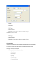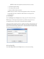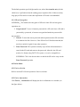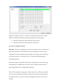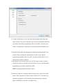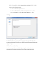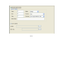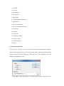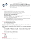
1
User's Guide XELTEK Superpro®7500 Series Ultra‐Fast, Stand‐Alone, 144pin Programmer of the Future XELTEK 1296 Kifer Rd. Unit 605 Sunnyvale, CA 94086 Tel: (408) 530‐8080 Fax: (408) 530‐0096 www.xeltek.com IMPORTANT! 1. This manual applies to SuperPro/7500. 2. Make sure the software installation is completed before connecting the programmer to PC. 3. Please read the manual carefully before using programmers. 4. Please use Xeltek Adapters. Non‐Xeltek adapters will cause error XELTEK 1296 Kifer Rd. Unit 605 Sunnyvale, CA 94086 Tel: (408) 530‐8080 Fax: (408) 530‐0096 www.xeltek.com SUPERPRO is the registered trademark of XELTEK. Distribution and sales of this product are intended for use by the original purchaser under the terms of the License Agreement. This document may not, in whole or part, be copied, photocopied, reproduced, translated or reduced to any electronic medium of machine‐readable form without prior consent in writing from XELTEK. The information in this document is subject to change without notice. Software Copyright 2012‐2020 XELTEK Userʹs Guide Copyright 2012‐2020 XELTEK Welcome Welcome to the world of Xeltek SUPERPRO programmers. Xeltek has produced the SUPERPRO line of IC programmers since 1985. Our motto is to provide high value products at affordable prices. In the past 27 years, Xeltek has produced a string of highly popular and successful programmers including SUPERPRO, SUPERPRO II, SUPERPRO III, SUPERPRO V, SUPERPRO 680, SUPERPRO 8000, SUPERPRO 3000U, and SUPERPRO 9000 models. SUPERPRO 3000U is the first model to incorporate both PC connected and stand‐ alone modes operations combined into one programmer. It is also the first programmer to break the barrier of 40,000 devices supported in the industry. SUPERPRO 3000U is by far the most popular IC programmer in the industry today. Pushing the barrier further, Xeltek is proud to announce the family of SUPERPRO 7500 programmers. SUPERPRO 7500 retains all the good features of SUPERPRO 3000U, but, in addition, it is designed to program today's large size devices efficiently and effectively. Feature Highlights • • • • • • • The SUPERPRO includes ultra high speed programming via 32bit RISC MCU device. This is especially suitable for programming high capacity NAND Flash devices A 144 pin driver support is built-in to provide efficient programming of large pin count devices, an additional pin expander module is not necessary to program large pin-count devices. The SUPERPRO operates with a PC for engineering purpose or in standalone mode, without a PC, for repeat production mode programming. This provides seamless migration from engineering to production. The SUPERPRO communicates through a USB 2.0 port and operates on most Pentium‐based, IBM compatible desktop/notebook computers. The SUPERPRO comes with a standard 48-pin DIP ZIF socket and supports optional socket adapters to accommodate PLCC, TSOP, SOIC, SOP, QFP, TSSOP and BGA package types. The programmer and software supports Windows XP, Windows Vista, and Windows 7. For authorized users, the SUPERPRO can provide for automatic generation of electronic serial numbers. User Manual Organization This manual includes the following major chapters, • An introduction to the SUPERPRO series, including the system requirements and the software and hardware installation • Detailed explanations on the commands and the programming procedures • Information about error messages and common problems • An Appendix that includes the customer support information Note: The software prevails in any discrepancy between it and the user manual, due to any upgrades of the software. The information in this document may be subject to change without notice. Chapter 1 Overview of SUPERPRO® 7500 This section provides a brief introduction of SUPERPRO (1.1), software features (1.2), structure of the handbook (1.3), system requirement for the installation (1.4), and package content (1.5). 1.1 Introduction to SUPERPRO The SUPERPRO is a menu-driven software that operates a series of cost-effective, reliable, and high-speed universal programmers. SUPERPRO communicates through a USB 2.0 port and operates with most IBM-compatible desktop and notebook computers that based on Pentium. Menu-driven software interface makes all the operations quite user-friendly. 1.2 Software feature The USB 2.0 Series supports: • • • • • • Windows XP, Windows Vista, and Windows 7 More than 43,000 types of devices, including E/EPROM, PLD, MCU, FLASH, etc. Compatible with many types of file formats, such as Binary, Intel (linear & segmented) Hex, Motorola S, Tektronix (linear & segmented), Jed, pof, etc. It supports a plug-in test (48 pins or less) to detect defective chips, improper insertion and pins that are poorly contacted. SUPERPRO has an integral full-screen buffer editorial environment with commands such as fill, copy, move, swap, etc. Electronic serial numbers are generated automatically. 1.3 Structure of this User's Guide The content of this User's Guide is structured into three major sections, Chapter 1 is an overview and introduction of the SUPERPRO, describing the system requirement, installation of the hardware and software. Chapter 2 - Chapter 5 are detailed specification and explanation of all the features, commands, and function modules. In Appendices, there are supportive information and guide for trouble-shooting 1.4 System requirements The minimum system configuration requires: • • • • • A desktop or laptop computer with Intel Pentium or an equivalent processor Windows XP, Windows Vista, and/or Windows 7 operating system 1 GB free space on the hard drive Standard (USB 2.0) compliant socket A CD drive 1.5 Package content A standard SUPERPRO programmer package includes: A Programming host module A DIP48 socket (SUPERPRO/7500 is accompanied with DIP48 EX0001) A Power supply unit A USB 2.0 connection cable A CD contains driver software A user's registration form Chapter 2 System Installation This chapter provides a brief guidance on how to install the SUPERPRO software and connect the programmer hardware properly. NOTE: To avoid complications during the installation process, you must setup the software before connecting the programming hardware (the USB device) to your computer. That is, installation through the "Add New Hardware Wizard" of Windows system is NOT recommended (this might lead to wrong drivers with a different compatible device ID). 2.1 Software Setup Select the software to setup your SUPERPRO programmer either from the CD‐ ROM or by downloading the program from the Xeltek website. Instructions for both methods are described below. 2.1.1 Software setup from CD 1. Insert the CD into the CD-ROM drive. 2. If the setup program does not start automatically, run SETUP.EXE located in the root directory. 3. Select the appropriate programmer model. 4. Click Setup. NOTE: Each model has its own software and they are NOT compatible. 2.1.2 Download the software from website and setup (recommended) You can also download the specific software for a certain model at Xeltek website: http://www.xeltek.com. Select the icon to download the appropriate file for your programmer. Once you have saved the file to your computer, run it to setup the software. The following procedure describes the setup process step by step. 1. Once the setup program is running, a dialog box displays to allow the user choosing a preferred language. Select one from the drop down list and click OK to continue 2. An installation wizard will be displayed (as illustrated below). Click Next to continue. 3. A License Agreement will be displayed. Click I Agree to continue. 4. Choose the Destination Location in which the driver software will be installed. Once the destination file folder is selected, click Next to proceed. 5. Another dialog box will be presented and allow the user to choose whether creating a start menu icon and/or a desktop icon. Once correctly check the tick box(es), click Next to continue. 6. Check the previous selections and click Install to start the installation NOTE: If you are using the Windows Vista system, the operation system may display the following dialog box to ask you whether to install the software. Select Install this driver software anyway. 7. Once the installation is completed, click Finish. 2.2 Hardware and Driver Installation After you set up the software, you can install the hardware and driver. The following procedure explains the installation process. NOTE: Do not follow these steps below if you have not yet setup the software (see section 2.1). 1. Make sure all other programs are closed during the installation process. 2. Connect the programmer module to the computer through the USB port. 3. Turn on the power switch of the programmer module. When you connect the new hardware, the system initiates the New Hardware Wizard, which locates the driver from the software you have just installed. The system displays alerts one at a time, illustrated below. The alerts on your system may be slightly different. 4. After you open the application software for the programmer, the system automatically starts the initialization. If it does not, make sure the programmer is securely connected to the computer and that the power switch is on. Chapter 3 Quick Guidance of the Software Features This chapter is a quick guidance of the SUPERPRO ® software. It describes the functions and features of the programmer that are most frequently used. The SUPERPRO 7500 provides two programmers in one, they are: PC mode for engineering and Stand-alone mode for production. • Under PC hosted mode, a PC controls the programmer via a high-speed USB connection to program a chip. • Under stand-alone mode, the user controls the programmer via 20-characters, 4-line LCD display with 6-KEY keypad. In this chapter, all the features being described are in PC mode, while the standalone mode is described elsewhere. 3.1 The User's Interface (main screen) The main SUPERPRO screen is illustrated below. Each part of the user interface is labeled with a number and described below. 1. The Menu Bar provides access to the File, Buffer, Device, Option, Project, and Help menus. 2. The Tool Bar offers quick access to many commonly used functions. 3. The Command Window enables shortcut to many commands and operations. 4. The Programmer Statue Panel shows the state of the current project and programmer. 5. The Device Panel shows the connected device. 6. The Buffer Panel shows the state of the buffer. 7. The File Panel shows some basic information of the loaded file. 8. The Log Window displays the operation history. A detailed specification of the Programmer Statue Panel is shown in the picture below and described accordingly to the numbered notation. 1. Module number and the ID of the programmer 2. Auto/Cancel button 3. Device name and the manufacturer information 4. Statue bar shows the success/failure of the programmer 5. Statistic information panel 6. Count down settings and information 7. Connectivity and progression of the programmer/project 8. Serial number 3.2 Programming Procedures This section provides information on steps for common procedures to programme devices using SUPERPRO 7500. Before using the programmer to program a device, make sure that the programmer is installed properly and that the computer and programmer are communicating successfully. Make sure that you have the appropriate adapter for your SMD devices, if applicable. Insert the chip correctly. Follow the guidelines of the standard chip insertion markings near the pin-driver socket. However, if you select SMD or a device that requires non-standard insertion, the system prompts you with the appropriate chip insertion. 3.2.1 Select the device To open the Device Selection window, choose one of the following options: • • Select the Device Selection icon Select the Device menu and select the Select Device (Device) option. The system then displays the Device Selection screen as shown below. NOTE: The red device name means that such device(s) need authorization to use. 3.2.2 Load data into buffer One can load data into the buffer by reading data either from a file or a master chip. To read data from a file, select Load File from the File menu. The system displays the Load File dialog box. To make sure the loaded data is correct one can review the information in the Buffer window. NOTE: Some Hex or S record files contain non-zero file initial address. In this case, enter the start address in the File Address box. To read the data from a master chip, complete the following steps: o Insert the master chip in the socket. o Select Read on the Device Operation window in the main screen. The data will be copied from the master chip to the buffer memory. o To make sure the loaded data is correct one can review the information in the Buffer window. o If desired, you can save the data to a disk for later use. NOTE: The read function is not available for some devices, including those have been encrypted. 3.2.3 Set options Click Operation Option from the Option menu to open the Operation Option screen. Set each of the following options: o Insertion Test indicates whether to check the pin contact. o Device ID Check indicates whether to check the ID of the device. o Beeper indicates whether the beeper alarms a sound when the operation succeeds/fails. o Auto Increment Function indicates an automatic increase in the label number written to each chip. o Address Change indicates whether a different start and end address shall be applied for the programming zone of the device. To set the order of the batch processing functions, select Edit Auto from the Options menu. The system displays the Edit Auto screen. For devices that include the configuration word, you must set the configuration word before programming to ensure that the chip can be used on the target system. The configuration words for some devices are contained in the data file. Therefore, the system automatically loads the configuration word into the configuration word buffer when loading the data file. For some devices, you must manually make the selection. Select Device Configuration Word from the Device menu to open the ConfigWord screen. Many devices must meet some special requirements for the programming of a chip, including special algorithms conventions. Read the device manual or instructions carefully and adjust the operation steps or buffer data as needed. If an adapter is required for programming, the system displays information about the adapter in the device information screen. 3.2.4 Execute programming Insert the chip properly into the socket. If the prompt information indicates a need for an adaptor, you may purchase the adapter. The operation procedure for the programming of a chip is described as the following steps: Blank Check NOTE: You can skip this step if the chip is brand new. The Blank Check fails on electrically erasable chips containing some information. In this case, perform the Erase operation first. You do not need to erase EPROM chips for which the data can be overwritten. Program Verify NOTE: This step is necessary. The chip must pass Verification before the programming can be implemented. Some chips provide only the accumulation check function, such as VerifyCRC instead of a unit-to-unit check function. Very few chips do not provide the accumulation check function. Security or Protect if encryption is required NOTE: You may need to set the configuration word before performing encryption. Refer to Device Configuration Word on page 37 for more information. Select Auto to finish all the operations in one step. Execute Production Mode to Program Chips in Batches Select Production Mode from the Option menu to program devices in large quantities. This function facilitates the job of the user who programs chips in batches. In order to program chips in batches, the programmer always conducts the insertion test. The programmer waits for the chip insertion to initiate while the system displays the following prompt: Please, insert a device into the socket. Once you have properly inserted the chip, the auto batch-processing command starts automatically. 3.3 Programming When Connected by Hub SUPERPRO® 7500 provides a connection hub and user can simultaneously operate multiple SUPERPRO® 7500 programmer by using the hub. Click menu Programmer -> Module Management, and select the number of the programmer you want to operate. Picture below shows the interface when simultaneously operating three programmers. Every programmer has a unique number. The programmer's first line of the LCD display will show the number of this programmer. The module that is selected at the time will be highlighted. The device that is going to be programmed can be different type(s) in each of the module that is connected through the hub. In normal mode, all operations (i.e. selecting devices, loading documents and programming) are carried out in the programmer that is selected and highlighted at the time being. In global configuration mode, all the operations are carried out in the programmer(s) that is selected with the check in tick-box(es). NOTE: Choose specified hub for XELTEK to connect SUPERPRO/7500, and currently up to 8 programmer can be operated simultaneously. ` Chapter 4 Functions and Commands This chapter provides a detailed specification and explanation of the SUPERPRO ® software. It includes the description of the functions and commands that is listed as below, • • • • • • File Menu and Tool Bar (4.1) Project Menu (4.2) Device Menu (4.3) Option Menu (4.4) Tool Bar (4.5) Log History Window (4.6) 4.1 File Menu and Tool Bar The File menu provides access to the commands of Load, Save, Recent Projects, and Exit. Each function is described in the following sections. 4.1.1 Load File There may be one or more data buffers in the device. If several data buffers are displayed after you have selected the device, refer to the name and the data manual for the meanings of the buffers. The two data types of the device are Data (HEX/ASCII) and Fuse. • • For most EPROM and SCM, the data type is Data (HEX/ASCII). The data type for PLD device is Fuse. After you select the device, the software automatically will identify the data buffer type. You can review the buffer data types if you open the Edit dialog box for the data buffer. When some file data are loaded into the data buffer, the following rules apply: • With a HEX/ASCII data buffer (EPROM, MCU etc.), the system assumes that 8 bits of the data are valid. • With a JEDEC buffer (PLD/PAL), the system considers the lowest bit (1 bit) of the file data valid. Select Load from the File menu to open the Load File dialog box, as illustrated below. The red labels refer to the numbered notations follow this figure. 1. Buffer. To select the Buffer name from the drop down list. The system loads the file data into the buffer accordingly. 2. File Name. To enter the name of the data file to load it, or you can select Browse and choose the file using the Select File box . 3. File Type. To select the type of the file from a drop down list. Different file types are included here, e.g. Binary, Intel Hex, Motorola S record, JEDEC, POF, TI, etc. 4. File Mode. To select one of the following File Modes from the drop down list: • • Normal to load the whole file Even to load the first byte and discard the second byte out of every two bytes • Odd to discard the first byte and load the second byte out of every two bytes • 1st byte of 4 to load first byte and discard the other three bytes out of every four bytes • 2nd byte of 4 to load the second byte and discard the other three bytes out of every four bytes • 3rd byte of 4 to load the third byte and discard the other three bytes out of every four bytes • 4th byte of 4 to load the fourth byte and discard the other three bytes out of every four bytes • 1st 2_byte of 4 to load the first two bytes and discard the other two bytes out of every four bytes • 2nd 2_byte of 4 to load the last two bytes and discard the other two bytes out of every four bytes 5. Buffer Address. To indicate a different initial address of the data being loaded into the buffer. 6. File Address. In case the file type has a non-zero start address, enter the data offset address in the File Address field. Make sure to enter the correct address, because an incorrect file offset address causes part of the buffer to be filled with FF (or incorrect data). 7. Buffer clear on data load. Tick this checkbox will enable the user to fill the data buffers with the specified data. NOTE: Ticking the checkbox of Custom File will disable most loading option. 4.1.2 Save File Select Save from the File menu to save data in the current buffer to a disk file. A dialog box titled as Save File will be displayed and the saving options are similar to those in section 4.1.1 Load File. 1. Buffer. 2. File Name 3. File Type 4. Buffer Address 5. Data Size. To enter the save data size in number of bytes. SUPERPRO® 7500 User's Guide 3. File Type 4. Buffer Address 5. Data Size. To enter the save data size in number of bytes. 4.2 Project Menu The project file contains all of the information and preparations before programming. It can also be used to restore the working environment that has been saved previously. The project file includes: • The current device's information, such as: o Manufacturer o Device type o Pin size o Data file name o Current buffer data NOTE: The buffer data may differ from the data file due to revisions. • • • All Operation Option settings The content of the Auto mode Software module related to the project NOTE: The project content is related to the programmer software. If the software has upgraded or has been re-installed to another folder, the saved project files become ineffective 4.2.1 Load Project Select Load Project from the Project menu to load a project file. Select the file in the File dialog box. Following the information that is provided by the project file, user can change the device(s), data in buffer, and operation option accordingly. If the project contains “dynamic password”, a random serial number will be displayed. User should offer the serial number to the project maker. The project maker generates password by the tool “Password Generator” (please refer to ““Password Generator” for details). Then User input the password and load the project. 4.2.2 Save Project Files Select Save Project Files from the Project menu to save the current working environment to a specified project file. To ensure the security of the data, you can encrypt the project file. When the option “Enter protected mode after loading the project” is selected, Dialog “Protected mode Setting” pops up. Please refer to “Protected mode” for details. Dynamic Password: Please refer to “Load project” and “Password Generator” for details. 4.2.3 Manage Project Library The stand-alone operation is when the programmer hardware is not connected to a computer, and uses information saved in its own module for volume production. The stand-alone file includes all the information needed for programming the device. This enable the user to prepare the project file(s) before starting the programmer's operation. The project file being saved in the stand-alone mode will be manageable using Manage Project Library function. This type of file can be stored in the SD card incorporated in the SUPERPRO® 7500 programmer. NOTE: 1) Besides using Manage Project Library function, user can also copy the project file(s) by SD card replication; 2) SD card's file system must be FAT32. The figure below shows a typical Manage Project Library window Some basic commands related to the project file operation are: • Send Project. This will send the existing project file(s) to the SD card. One can also encrypt the SD card to protect the data. • Delete Project. To delete the project being selected. There are many SD card manufacturers in the market and the quality varies a lot across different brands. The ones from Kingston TM, and SandiskTM is recommended. The default operation speed is high transfer rate, where low transfer rate (tick the check-box) is preferable when the sending project operation fails. If there are many large project files need to be sent, then replication of SD card is recommended. 4.2.4 SD card encryption SUPERPRO® 7500 enables the encryption of SD card. Some SD card encryption operations are, • Set password. To set a 6-character password for a SD card. Once a SD card is protected by a password, it becomes encrypted and needs the password for any operation. • Unlock. To enter the correct password enable operation on the SD card when it is connected on-line. However, if the SD card is off-line/disconnected, the user has to unlock it again for any other operation. • Erase Password. This operation actually wipes all the information that is stored in the SD card and removes the password. After this, the SD card needs to be format using FAT32 file system, so as to be compatible to SUPERPRO® 7500. One does not have to unlock the SD card to carry out the Erase Password operation. 4.3 Device Menu 4.3.1 Device selection Refer to section 3.2.1 for the operation of device selection. 4.3.2 Device information Click Device information will display the device information in a window (see the figure below). 4.3.3 Manage data in buffer There are two major types of buffer, Fuse Buffer and Data Buffer (HEX/ASCII buffer). In following section the operations of these two types of buffer is described and a typical buffer operation window is shown below. 4.3.3.1 HEX/ASCII Data Buffer • Locate. Enter the address of the data you wish to display and select OK to quickly move the cursor to the desired location. • Fill. To fill the data in the buffer between the Start and End address. For Fuse buffer, the data must be 0 or 1, and for Data Buffer (HEX/ASCII buffer) • Copy. Select Copy to open the Copy Buffer dialog box. o Enter the start address in the Start Address field. o Enter the end address in the End Address field. o Select OK to copy the data between the start address and the end address, beginning with a new address. Otherwise, select Cancel. • Radix. Select Radix to toggle between the HEX and DEC memory address display. • Search. Select Search to search for a specified string. Select Search Next to begin the next search for the specified string • Swap. Select Swap to open the Word Swap dialog box, illustrated below. Select the Word Width option to swap high byte and low byte according to the specified width in the address range and select OK. Otherwise, select Cancel. For example, if the data buffer address 0-10(HEX) is: 12 34 56 78 90 AA BB CC - DD EE FF 11 22 33 44 55 Then after swapping the data, it would look like this according to the selected word width: o 16 Bits (2 bytes) 34 12 78 56 AA 90 CC BB o 32 Bits (4 bytes) 78 56 34 12 CC BB AA 90 - 11 FF EE DD 55 44 33 22 o 64 Bits (8 bytes) CC BB AA 90 78 56 34 12 - 55 44 33 22 11 FF EE DD 4.3.3.2 Fuse Buffer When you select Edit from the Buffer menu with the appropriate file type, the system opens the Fuse Buffer Edit window, illustrated below. The data for editing is either 0 or 1. Refer to the data manual of the device and the JEDEC to determine which of the following explanations for the data apply. • • 1 represents an intact fuse and 0 represents a blown fuse, or 1 represents a blown fuse and 0 represents an intact fuse 4.3.4 Device Configuration Word Important: The device configuration word varies from device to device. Refer to the device data manual for more information about the configuration words. Set the configuration words according to the requirements of your target system. Otherwise, you cannot use the device normally even if it is normal when preparing and verifying the program. Some single-chip microcomputers allow special working modes, such as the storage area mapping, the watchdog time, the clock, or the encryption. Set these special modes through the Device Configuration Word option. The user files contain the configuration words of some devices. When you load these files, the system automatically loads the configuration words into the configuration word buffer. However, you must select the configuration words for some devices manually. Select Device Configuration Word from the Device menu to open the ConfigWord dialog box. The following sample illustration shows the configuration word for EON,EN25B16(Bottom Boot). It contains the watchdog and three protection modes Some single-chip microcomputers include many items for the configuration word. The items may appear on separate tabs or pages. Make sure to set all the items on all pages before programming a chip. The input of the configuration word can be divided into several ways: • • • • The 8-bit (byte) edit box input The 16-bit (word) edit box input The single choice input (select and deselect, choose one out of two) The multiple choice input (choose one out of many) The configuration words for chip programming are classified into two categories: • If the configuration word contains some protected items, then you cannot verify the items after preparing the program. When preparing the program, the programmer automatically shields the protected items and writes the other items. Select Security or Protection to write the protected items. NOTE: If you select None as the Protection option, the system does NOT carry out an operation when performing Security or Protection. • In some devices, the configuration words cannot be separated, so the system does not write the configuration word when preparing the program. To write the configuration word in these cases, select the corresponding item, such as Write_Option. Some FLASH devices also use the configuration word for the protect operation and to execute and display the segment protection. 4.4 Option Menu The Option menu includes items to help you program in a specific mode to meet the targeted system requirements. Before programming a chip, make sure to select the necessary settings. The General view of the Operation Option screen is illustrated below. The Operation Option screen includes four tabs: • • • • General Buffer Auto.Inc Count Each view is explained in the following sections 4.4.1 General 1. For chips with 48 pins or less or for chips with an adaptor that reduces the chip to 48 pins or less, select Insertion Test to have the programmer check the pin contact status before programming. The test includes a check for poor contact, wrong direction, chip insertion, and chip insertion orientation errors. 2. Select ID Check to have the programmer read the Electronic Identifier Code from the chip to identify the manufacturer, the device type and the programming algorithm code. If you have already selected the device, the default for this option is checked. 3. Select Beeper On to turn the beeper on or off. The beeper makes a sound to indicate the results of operations such as Insertion Test error, ID unmatched, programming successfully completed or failed. NOTE: Not all programmers include a beeper. 4. Indicate the mode for verifying the data by selecting one of the Verify Mode options. These options refer to the voltage of the pin VCC, which may vary when the programmer verifies the data. The manufacturer provides the MinVcc and MaxVcc values for verifying the data. VCC(+/- 5%) or VCC(+/- 10%) is adopted for the verification. If VCC = 5.00V, select one of the following options: • VCC = 5.00V and verify the data once • VCC = 4.75V and VCC = 5.25V, and verify the data twice (+/- 5%) • VCC=4.50V and VCC=5.50V, and verify the data twice (+/- 10%) 4.4.2 Buffer The default programming method is to program the device from the start address to the end address. However, you may choose to program only a part of the chip, such as with most E/EPROM (FLASH) devices. (Double click on buffer name and set the range of programming) 4.4.3 Auto Increment (Auto.Inc) Auto Increment provides two methods of generating the serial numbers: Auto Increment and User Defined. This function is not available in stand-alone mode. 37 of 51 NOTE: The serial number is the content required by some applications that must be written in a certain area for every chip. This information includes the product sequence number and the MAC address. To have the software generate the serial number, select Enable AutoIncrement. 1. Enter the automatic start buffer address in the Start Addr field. 2. Enter the automatic end buffer address in the End Addr field. 3. Enter an increment value less than 10 in the Inc. Step field. 4. The AutoInc Format defines the start value and the overflow value. The overflow value is the number at which the increment ceases and carries to the next address, which becomes the new start value. • • Select Binary to set the start value as 0 and the overflow value as 256. Select ASCII Decimal to set the start value as 30 (hexadecimal representation of 0) and the overflow value as 39+1 (the hexadecimal representation of 9). • Select ASCII Hex to set the start value as 30 (hexadecimal representation of 0) and the overflow value as 46+1 (the hexadecimal representation of a number greater than F, where 9+1=A). To define the increase of the serial number, select User's Definition. You must be authorized to use this function. If so, you can change the data as desired in the 4K byte range. 4.4.4 Count The Count view of the Operation Option screen is illustrated below. This screen allows you to change the default setting regarding the statistical work of the programming status. In the default case, it is only effective for the function program". 4.5 Edit Auto The Auto function organizes the different functions of the device into a sequential group and carries out the functions in order, similar to a batch command. Edit Auto enables edit functions and operations, in order to automatically execute the programming procedure according to pre-arranged functions and operations. As can be seen from the figure above, user can select one certain function/operation and Add, Delete the selected one, or Delete All to cancel all the previous arrangement. 4.6 Tool Bar The tool bar provides a quick way to execute common functions. The toolbar from the main SUPERPRO screen is illustrated below. Each tool is labeled with a number and described below. 1. Load file 2. Save file 3. Load project 4. Save project 5. Edit buffer 6. Calculating the Checksum 7. Select device 8. Device information 9. Device configuration word 10. Edit Auto 11. Option 12. Logic test 13. Production mode 14. Factory mode 15. Global settings 16. Help 4.7 Log History Window User can create a log file to have the system save Operation Information window content into a log file when you exit the program. Select Log File from the Option menu to open the Log File dialog box, illustrated below. The red labels refer to the numbered explanations below 1. Select No to delete the log file. The system will not create a log file on exit. 2. Select New to overwrite the existing log file every time the program starts. 3. Select Append to add the log file information at the end of the existing log file each time the program starts. 4. Enter, edit or Browse for the full path name of the log file in the Log file's name: field. Chapter 5 Frequently Asked Questions (FAQ) You can monitor the programmer operations through the Operation Information Window and message window. This chapter helps define common problems related to programmer actions and errors. 5.1 Dealing with Data Files This section explains common problems involving the File Type dialog box. 5.1.1 Solve Invalid File Type or File Data Overflow Error The data for programming is usually stored in the data file. Commonly used formats are Intel Hex, Motorola and Tektronix. The files of these formats keep data in text mode, which include data and address information. Because the offset address is not always zero, you may incur errors when loading the file directly. For example, the location of data in buffer (as viewed in the Edit Buffer window) may be incorrect or you may receive an error message when loading the file, such as Invalid file type, or all file data overflow. Select one of the following options to solve this problem. • • Confirm the file type and ensure the buffer can load all the files. Find the offset address of the file. When loading the file, select the Show Offset Address (Minimize) After Loading option to display the start address of the file after the file is loaded. 5.1.2 Separate File Data for Programming By using the File Mode selection in the File Type dialog box, you can select the data of a file and write it to several chips of the same type. This allows you to load the file several times according to your needs. There are three methods for separating the file data: • Based on byte (8bit), divide the file into two parts by the odd and even address. Program the two parts into two chips respectively. When loading the file, select Even as the File Mode to write the data in the addresses 0,2,4,6, etc. to one chip. Select Odd as the File mode to write the data at the address 1,3,5,7, etc. to the other chip. • Based on the byte (8-bit), divide the file into four parts by address of the first byte, the second byte, the third byte and the fourth byte out of every four bytes. Program the four parts to four chips respectively. When loading the file, select the 1st byte of 4 as the File Mode to write the data in the addresses 0, 4, 8, 12 (or C if HEX), etc. to one chip. Then select 2nd byte of 4, 3rd byte of 4, and finally 4th byte of 4 to write the remaining data to the other three chips. • Based on the word (16-bit), divide the file into two parts by address of the first two bytes and the last two bytes out of every four bytes. Program the two parts to two chips respectively. When loading the file, select the 1st two bytes of 4 as the File Mode to write the data in the addresses 0, 1, 5, 6, etc. to one chip. Then select 2nd two bytes of 4 to write the remaining data to the other chip. 5.1.3 Program Two or More Files to One Chip User can load several files into the buffer and write them to the chip. The following explanation gives an example of programming three files (Sample1, Sample2, and Sample3) to one chip. The example assumes the following: • Write the data from the address 200 (Hex) of the file Sample1 to the address 0 of the chip. • Write the data from the address 0 (Hex) of the file Sample2 to the address 3000 • (Hex) of the chip. Write the data from the address 4000 (Hex) of the file Sample3 to the address 4000 (Hex) of the chip. 1. Select Edit from the Buffer menu. Make sure that the Buffer clear on data load option is not checked. 2. Select Load from the File menu to load the Sample1 file. o In the Buffer Address field, enter 0. o In the File Address field, enter 200. 3. Select Load from the File menu to load the Sample2 file. o In the Buffer Address field, enter 3000. o 4. Select Load from the File menu to load the Sample3 file. o In the Buffer Address field, enter 4000. o In the File Address field, enter 4000. 5. Continue with programming. If there are no changes in the file requirements or content of the three files (Sample1, Sample2, and Sample3), you can save the data in buffer to a new file, such as Sample4, for easy loading and programming next time. 5.1.4 POF Format Files When programming ALTERA PLD devices the system saves the data in POF format files. When loading a POF Format file, the system displays a File Type dialog box. Select one of the following: 1. POF file: The system transforms the data into the Fuse data and checks the data when you load it to the buffer. You may receive one of the following errors: o Unmatched file to this chip: This POF file does not match this chip. The POF file is related to the device when it is compiled. The error indicates that this POF file is not for this device. Replace the chip with a matched one. o The POF file has errors. o Load POF file dll error (not found): An auxiliary file has errors. Contact technical support for assistance. 2. Files of other formats are mainly the JED files. The system saves data in the buffer in a JED file after reading the chip. You can use this format the next time you load the file. 5.2 Adapter Selection The standard programmer configuration supports the DIP devices with 48 or less pins. If you want your programmer to support a device with more than 48 pins, you will need an adapter. There are two types of adapters: universal and specific. • Universal adapters are applicable for all devices of the same encapsulation and the same number of pins. • Specific adapters are applicable for certain devices only. For example, if the number of the pins for economical programmer hardware is not enough, specific adapters may solve the ‚insufficient number of the pins‛ problem. To use devices with pins between 48 and 144, you can choose either the universal adapter or the specific adapter. To use devices with pins more than 144, you must use the specific adapter. The Device Information screen displays adapter information. 5.3 Other Messages Other error messages are explained below. • Please edit 'Auto' first: The Auto consequence is blank. Edit Auto and try again. • Enter a string to search for: The Hex Edit Search dialog box is blank. Make sure to enter a specified string or ASCII codes to search for in the Buffer Edit dialog box. • The string for search is blank. Input it in Search dialog: Enter a string in the Buffer Edit dialog box. Then you can use The first time search, Continue to search, or Search Next functions. • Search pattern not found!: The system did not find a matched string or ASCII code. • User chip is MfgID = 0089, DeviID = 0051: This display on the Operation Information window indicates that the chip's ID detection function detected a different ID than specified in the manual. • ID check error. Ignore: You can ignore the detected ID error and continue the operation. • ID check error: The operation stops because of the ID check error. If you have good knowledge of this chip, you may ignore the ID error and continue the operation. Exercise caution to avoid damaging the chip. • Pin check error. Ignore: The system indicates an error during the pin check. Ignore it and continue. • Pin check error: An error occurred during the pin check, and the operation ceased. • Programmer not found: The programmer is not connected to the PC or it is connected improperly. Check the connection. • Programmer not ready: Turn off the programmer power switch and turn it on again after a few seconds. • Programmer is running: The programmer hardware is operating. Wait until the operation is finished. • • • File open error: The open file operation failed. Out of Memory: The memory overflows. Production mode isn't available for this chip: Since the production mode is dependent on the pin check, the chips without pin check function are not applicable for production mode. • • • Cancel production mode: Cancel the production mode. Too long file name: The file name is too long. User cancel: The system displays this message after you select Cancel on the Status bar. • • Can't cancel!: The Cancel operation has failed. Not a project file: The file selected is not a project file. After the software is updated, the software may not be able to identify a previously created file. You will need to create the file again. Appendix XELTEK periodically publishes upgrade software on the XELTEK website. You can download and upgrade your software from the website. Non‐users may download the software for evaluation. Troubleshooting If the User Manual does not answer your questions, first contact your sales agent or the distributor. If you still need technical assistance you can call XELTEK between Mon‐Fri 7:30AM‐12:00PM & 1:00PM ‐ 4:30PM (PST). Make sure you have your product serial number before calling. Before contacting XELTEK, check the following to ensure you get the best service. • • Read the User Manual. If you receive an error message that is not explained: o Make sure you can repeat the circumstances that created the error. o Write down the error message. • • Make sure you have your product serial number. Check your computer configuration, including computer brand, free memory size before starting the software, the video adapter brand, and the operating system. • Make sure you are at your computer when you call so the engineer can guide you through the solution. Contact Information XeltekInc. 1296 Kifer Rd. Suite # 605 Sunnyvale, CA 94086 United States General Consultation 001‐408‐530‐8080 Order/Sales 001‐408‐530‐8080 Email: [email protected] Technical Support 001‐408‐530‐8080 Email: [email protected] Fax: 001‐408‐530‐0096 Website: http://www.xeltek.com License Agreement The copyright of the program and the User’s Guide remain the property of XELTEK. You may: 1. Copy the program for back‐up purposes ONLY in support of its use on a single computer. 2. Transfer the program and license to another party if the other party agrees to accept the terms and conditions of this agreement. You may not: 1. Use this product on a computer system or network that allows the program to be operated by more than one user at the same time. 2. Modify, copy, or transfer the User's Guide or other documentation or any copy. 3. Decompile or disassemble any program modules or encrypted devices.