1
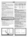
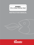
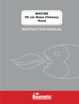
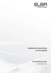
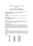
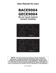
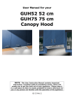
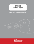
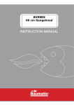
Instructions and installation
manual
MODELS:
BSGH95-ANZ / BSGH75-ANZ
BSGH64-ANZ / BSGH32-ANZ
BSGH30-ANZ
PLEASE READ THIS MANUAL BEFORE
INSTALLING THE COOKTOP.
COD. 04067IR 26.02.2013
DESCRIPTION OF COOKTOP
6
7
10
5
8
6
9
6
7
6
7
12 11
10 9
10 11 12
8
Natural
14.5 MJ/h
12.0 MJ/h
5.4 MJ/h
7.1 MJ/h
4.1 MJ/h
1 Ultra rapid gas burner/WOK
2 Rapid gas burner
3 Semirapid reduced gas burner
4 Semirapid gas burner
5 Auxiliary gas burner
6 Pan stands support 2F
7 Pan stands support 1F
8 Burner n° 2 control knob
9 Burner n° 5 control knob
10 Burner n° 1 control knob
11 Burner n° 3 control knob
12 Burner n° 4 control knob
8
9
U-LPG
12.6 MJ/h
10.4 MJ/h
4.9 MJ/h
6.3 MJ/h
3.6 MJ/h
To use the WOK pan support on ultra rapid
gas burner only.
Put it on the ultra rapid pan support and
make sure of the stability (see fig. A).
Fig. A
Attention: this appliance has been manufactured for domestic use only. Do not modify this
appliance.
2
USE
1) BURNERS
A diagram is screen-printed above each knob on the
front panel. This diagram indicates to which burner
the knob in question corresponds. After having
opened the gas mains or gas bottle tap, light the
burners as described below:
- automatic electrical ignition
Push and turn the knob corresponding to the
required burner in an anticlockwise direction until it
reaches the full on position (large flame fig. 1), then
depress the knob.
- Lighting burners equipped with flame failure
device
The knobs of burners equipped with flame failure
device must be turned in an anticlockwise direction
until they reach the full on position (large flame fig. 1)
and come to a stop. Now depress the knob in
question and repeat the previously indicated
operations.
Keep the knob depressed for about 10 seconds once
the burner has ignited.
Note: you are advised not to try and light a
burner if the flame divider (burner Cap) is not
correctly placed
In the event of the Burner flames being accidentally
extinguished, turn off the burner control and do not
attempt to re-ignite the burner for a least 1 minute.
HOW TO USE THE BURNERS
Bear in mind the following indications in order to
achieve maximum efficiency with the least possible
gas consumption:
- Use adequate pans for each burner (consult the
following table and fig. 2).
- When the pan comes to the boil, set the knob to
the reduced rate position (small flame fig. 1).
- Always place a lid on the pans.
- Use only pan with a flat bottom.
FIG. 1
Burners
Power ratings
Natural
Ultra rapid/WOK 14.5 MJ/h 12.6 MJ/h
Rapid
Semirapid reduced
Semirapid
Auxiliary
12.0 MJ/h 10.4 MJ/h
5.4 MJ/h 4.9 MJ/h
7.1 MJ/h
4.1 MJ/h
6.3 MJ/h
3.6 MJ/h
24 ÷ 26
20 ÷ 22
16 ÷ 18
16 ÷ 18
10 ÷ 14
WARNINGS:
- Burners with flame failure device may only be
ignited when the relative knob has been set to
the Full on position (large flame fig. 1).
- Matches can be used to ignite the burners in a
blackout situation.
- Never leave the appliance unattended when the
burners are being used. Make sure there are no
children in the near vicinity. Particularly make
sure that the pan handles are correctly
positioned and keep a check on foods
requiring oil and grease to cook since these
products can easily catch fire.
- The appliance must not be used by people
(including children) with impaired mental or
physical capacities, or without experience of
using electrical devices, unless supervised or
instructed by an expert adult responsible for
their care and safety. Children should not be
allowed to play with the equipment.
- Never use aerosols in the vicinity of this appliance
while it is in operation.
- Should a crack appear on the surface of the glass,
disconnect the appliance from the electricity
supply immediately.
- Do not place pans with an unstable or deformed
bottom on the burner, as these may tip or spill their
contents, causing accidents.
- Do not store or use flammable liquids or items
in the vicinity of the cooktop.
- Do not use the hob as a work surface.
- This product is not to be installed in marine
crafts, caravans, or mobile homes.
- Containers wider than the unit are not
recommended.
- Avoid scraping the pans on the glass surface,
as the surface may become scratched.
- Do not modify this appliance.
FIG. 2
3
U-LPG
Pan Ø
in cm
USE
WARNINGS AND ADVICE FOR THE USER:
- Do not attempt to change the technical characteristics of the product because it can be dangerous.
- If you decide longer use this appliance any more (or replace an old model), before disposing of it,
make it inoperative in conformity with current law on the protection of health and the prevention of
environmental pollution by making its dangerous parts harmless, especially for children who
might play on an abandoned appliance.
- Do not touch the appliance with wet or damp hands or feet.
- Do not use the appliance barefoot.
- The manufacturer will not be liable for any damage resulting from improper, incorrect or
unreasonable use.
- During, and immediately after operation, some parts of the cooktop are very hot: avoid touching
them.
- After using the cook top, make sure that the knob is in the closed position and close the main tap
of the gas supply or gas cylinder.
- If the gas taps are not operating correctly, call the Customer Care Department.
Abnormal operations:
Any of the following are considered to be anormal operation and may require servicing:
- Yellow tipping of the hob burner flame.
- Sooting up of cooking utensils.
- Burners not igniting properly.
- Burners failing to remain alight.
- Burner extinguished by cupboard doors.
- Gas valves which are difficult to turn.
Symbol 1
Do not place anything, eg. flame tamer, asbestos
mat, between pan and pan support as serious
damage to the appliance my result.
Symbol 2
Do not remove the pan support and enclose the
burner with a wok stand as this will concentrate and
deflect heat onto the cooktop.
Symbol 3
Do not use large pots or heavy weights which can
bend the pan support or deflect flame onto the
cooktop.
Symbol 4
Locate pan centrally over the burner so that it is
stable and does not overhang the appliance.
Symbol 5
Use only a wok support supplied or recommended by
the manufacturer of the appliance.
4
CLEANING
IMPORTANT:
1f - 2f (30 Cm) Vetroceramic
Always disconnect the appliance from the gas If you wish to maintain the shine of the ceramic
and electricity mains before carrying out any surface, treat the glass with a silicon-based film
cleaning operation.
product before use to protect the surface against
water and dirt. This protective film is not durable, so
it is advisable to repeat the application of the product
2) COOKTOP
Periodically wash the cooktop, the pan stand frequently.
support, the enamelled burner caps “C” and the It is very important to clean the hob every time you
burner heads “M” (see fig. 3) with lukewarm soapy use it, while the glass is still warm.
water. Following this, all parts should be thoroughly Do not clean using abrasive metal scourers, powder
rinsed and dried. Never wash them while they are abrasives or corrosive sprays.
Depending on the degree of dirt, we recommend:
still warm and never use abrasive powders.
Do not allow vinegar, coffee, milk, salted water, - for light stains, a damp sponge is sufficient.
lemon or tomato juice from remaining in contact with - Tough, encrusted dirt is easily eliminated using a
scraper (fig. 3/A), not supplied with the hob, but
the surfaces for long periods of time.
easy to find in local stores. Use the scraper
carefully to avoid damaging the hob.
WARNINGS:
Comply with the following instructions, before - Traces of liquid spilled from pans can be
remounting the parts:
eliminated with vinegar or lemon juice.
- Check that burner head slots “M” (fig. 3) have - Never allow sugar or sugary foods to fall on the
not become clogged by foreign bodies.
hob while cooking. Should this occur, switch off
- Check that the enamelled burner cap “C” (fig. 3) has the hob and clean it immediately with hot water,
been correctly positioned on the burner head. It must using a scraper on hot spills.
be steady.
- As time goes by metallic reflections, colouring or
- Do not force the taps if they are difficult to scratches may appear due to poor cleaning and
open or close. Contact an Authorised Service
the incorrect movement of pans. Scratches are
Centre for repairs.
hard to eliminate but do not affect the correct
- Don’t use steam jets for cleaning the cooktop.
operation of your hob.
- Do not use jets of steam to clean the appliance.
Note: continuous use could cause the
burners to change colour due to the high
temperature.
FIG. 3/A
FIG. 3
5
INSTALLATION
TECHNICAL INFORMATION
FOR THE INSTALLER
3) INSTALLING THE COOKTOP
Check that the appliance is in a good condition after
having removed the outer packaging and internal
wrappings from around the various loose parts. In
case of doubt, do not use the appliance and contact
qualified personnel.
Never leave the packaging materials (cardboard,
bags, polystyrene foam, nails, etc.) within
children’s reach since they could become
potential sources of danger.
The measurements of the opening made in the top of
the modular cabinet and into which the cooktop will be
installed are indicated in either fig. 4. Always comply
with the measurements given for the hole into which
the appliance will be recessed (see fig. 4).
The appliance belongs to class 3 and is
therefore subject to all the provisions
established by the provisions governing such
appliances.
Any adjoining wall surface situated within 200 mm
from the edge of any hob burner must be a suitable
non-combustible material for a height of 150 mm for
the entire length of the hob. Any combustible
construction above the top of the burner and no
construction shall be within 450 mm above the top
of the burner. A minimum depth of 70 mm from the
top of the work surface must be provided for this
appliance.
This appliance shall be installed only by authorised
personnel and in accordance with the
manufacturer’s installation instructions, local gas
fitting regulations, municipal codes, electrical wiring
regulations, NZS5261:2003, AS 5601 - Gas
Installation and any other statutory regulations.
Ventilation must be in accordance with AS 5601,
NZS5261:2003 - Gas installation. In general, the
appliance should have adequate ventilation for
complete combustion of gas, proper flueing and
to maintain temperature of immediate
surroundings safe limits.
The wall and bench surfaces must be capable of
sustaining temperatures of 75 °C. All laminates,
fixing adhesive and surfacing materials should
be certified suitable for this temperature.
CAUTION:
the installer shall test the appliance
before leaving. Test the safety
operation of the ignition system on all
burners individually and combined.
COMPLY WITH THE DIMENSIONS (in mm)
A
B
1F-2F (30)
282
473
5F (70)
645
473
4F (60)
5F (90)
553
833
C
59
D
59
E
100 min.
473
63.5
63.5 173.5 min.
475
62.5
62.5
63.5
63.5 173.5 min.
Caution: Do not allow the glass (A)
lay directly on the work top. it is the
bottomshelf (B) that has to be in
touch with the work top (see
fig. 4/A).
73.5 min.
FIG. 4
FIG. 4/A
6
4) FIXING THE COOKTOP
INSTALLATION
- When the appliance is installed so that the base
can be touched, we recommend fitting a
protecting shield. This shield must be at least
70 mm below the base of the bench top (fig. 4).
Timber or other suitable material may be used
provided it is capable of withstanding the
appliance temperatures. Ensure that the supply
connection point is accessible with the appliance
installed. To facilitate shield may need to be
removable.
The cooktop has a special seal which prevents
liquid from getting into the cabinet. Strictly comply
with the following instructions in order to correctly
apply this seal:
- Take off all the movable parts of the hob.
- Cut the seal in 4 parts of the necessary lenght to
positionning it on the 4 edges of the glass.
- Overturn the cooktop and correctly position seal
“E” (fig. 5) under the edge of the cooktop itself,
so that the outer side of the seal perfectly
matches the outer edge of the cooktop. The ends
of the strips must fit together without overlapping.
- Evenly and securely fix the seal to the cooktop,
pressing into place with the fingers and remove
the strip of protective paper from the seal and set
the plate into the hole made in the cabinet.
- Position the hob in the hole in the unit and fasten it in
place using the appropriate screws “F” and the
fastening hooks “G” (fig. 6).
NOTE: do not fix the cooktop into the bench
with sealant (ie silicon) as this may void the
warranty. Use only the seals provided.
IMPORTANT: a perfect installation,
adjustment or transformation of the cook top
to use other gases requires a QUALIFIED
INSTALLER: a failure to follow this rule will
void the warranty.
FIG. 6
FIG. 5
7
5) GAS CONNECTION
INSTALLATION
Liquified Petroleum Gas.
In a Universal LP Gas installation the gas
regulation is made at the gas cylinder and
regulation at the appliance is not required. To
connect supply to the appliance use transition
pieces
as
shown
in
figure 8. These pieces are supplied with the
appliance on purchase.
The gas connection is located in the rear and on
the underside of the appliance 100 mm from the
right hand side.
There are two ways to carry out the connection to
the main gas line:
A. The cooktop can be connected with rigid pipe
as specified in AS5601 table 3.1.
B. If installing with a hose assembly, install with a
hose assembly that complies with AS/ANZ 1869
(AGA Approved), 10 mm ID, class B or D, no more
than 1.2 m long and in accordance with AS5601.
Ensure that the hose does not contact the hot
surfaces of the cooktop, oven, dishwasher or any
other appliance that may be installed underneath
or next to the cooktop. The hose should not be
subjected to abrasion, kinking or permanent
deformation and should be able to be inspected
along its entire length with the cooktop in the
installed position.
Unions compatible with the hose fittings must be
used and all connections tested for gas leaks.
The gas supply connection for the hose assembly
must be accessible.
WARNING:
THE BURNER FLAME MUST BE ADJUSTED BY
THE INSTALLER.
FAULTY INSTALLATION WILL NOT BE
COVERED UNDER WARRANTY.
THE APPLIANCE IS FACTORY SET FOR
NATURAL GAS. THE TEST POINT PRESSURE
SHOULD BE ADJUSTED TO 1.00kPa WITH THE
WOK BURNER OPERATING AT MAXIMUM.
Warning: ensure that the hose assembly is
restrained from accidental contact with the flue or
flue outlet of an underbench oven.
Natural Gas
Natural Gas installations require the connection of
a gas regulator at the appliance. This regulator is
supplied with the appliance on purchase.
Assemble the regulator (noting the gas flow
direction) and transition pieces (supplied with the
appliance), in accordance with figure 7.
The transition piece on the supply side of the
regulator must be provided by the installer.
FIG. 8
FIG. 7
8
INSTALLATION
6) ELECTRICAL CONNECTION
Before performing any service on the electrical
part of the appliance, it must absolutely be
disconnected from the electrical network.
IMPORTANT: the appliance must be installed
following the manufacturer's instructions. The
manufacturer will not be liable for injury to
persons or animals or property damage caused
by an incorrect installation.
If the installation requires modifications to
the home's electrical system or if the
socket is incompatible with the appliance's
plug, have changes or replacements
performed by professionally-qualified
person. In particular, this person must also
make sure that the section of the wires of
the socket is suitable for the power
absorbed by the appliance.
The appliance is supplied with a 1800 mm long
flexible supply lead.
The point of attachment for this lead is located at
the rear and on the underside of the appliance
380 mm from the right hand side.
The voltage and power consumption are detailed
on the underside of the appliance. Ensure that the
appliance is correctly rated to the supply.
Connect appliance by way of a switched power
point.
THE APPLIANCE MUST BE EARTHED
Ensure that this power point is properly earthed.
Look at the connection wiring diagrams
alongside.
Warning: in order to avoid any hazard, any
electrical work performed on this equipment or
its associated wiring, should only be done by a
qualified person.
The socket outlet for this cooktop shall be
installed near the cooktop and shall be easily
accessible.
The electrical connections of the appliance
must be carried out in compliance with the
provisions and standards in force.
Before connecting the appliance, check that:
- The voltage matches the value shown on the
specification plate and the section of the wires of
the electrical system can support the load, which
is also indicated on the specification plate.
- The electrical capacity of the mains supply and
current sockets suit the maximum power rating
of the appliance (consult the data label applied to
the underside of the cooktop).
- The socket or system has an efficient earth
connection in compliance with the provisions and
standards in force. The manufacturer declines all
responsibility for failing to comply with these
provisions.
9
ADJUSTMENTS
Always disconnect the appliance from the
electricity main before making any adjustments.
All seals must be replaced by the technician at
the end of any adjustments or regulations.
Our burners do not require primary air
adjustment.
a) Data Label
The Data Label is located on the underside of the
cooktop. A duplicate Data Label is supplied to
adhere in an accessible area next to the cooktop.
This cooktop is suitable for Natural Gas and
Universal LP Gas; ensure that the available gas
supply matches the Data Label.
b) Before Leaving
Check that there are no gas leaks, but do not use a
naked flame to detect gas leaks. Ignite all burners
to ensure correct operation of gas valves, burners,
ignition and if fitted, flame failure valves. Turn gas
taps to low flame position and observe stability of
the flame. When satisfied with the cooktop, please
instruct the user on the correct method of operation.
In case the appliance fails to operate correctly after
all checks have been carried out, refer to the
authorised service provider in your area.
FIG. 9
7) TAPS
Our taps are suitable for all gas, they are male
conical type.
“Reduced rate” adjustment
- Switch on the burner and turn the relative knob to the
“Reduced rate” position (small flame fig.1- pag. 3).
- Remove knob “M” (fig. 9 and 9/A) of the tap, which
is simply pressed on to its rod. The by-pass for
minimal rate regulation can be: beside the tap (fig.
9) or inside the shaft. In any case, to access to
regulation, it can be done through the insertion of
a small screwdriver ‘’D’’ beside the tap (fig. 9) or in
the hole ‘’C’’ inside the shaft of ta p
(fig 9/A). Turn the throttle screw to the right or left
until the burner flame has been adequately
regulated to the “Reduced rate” position.
The flame should not be too low: the lowest small
flame should be continuous and steady. Reassemble the several components.
It is understood that only burners operating
with Natural gas should be subjected to the
above mentioned adjustments.
FIG. 9/A
CONVERSIONS
8) UNIVERSAL LP GAS TO NATURAL GAS
CONVERSION PROCEDURE
9) NATURAL GAS TO UNIVERSAL LP GAS
CONVERSION PROCEDURE
Appliance models: Gas stainless steel cooktop
models:
Appliance models: Gas stainless steel cooktop
models:
BSGH30-ANZ
BSGH32-ANZ
BSGH64-ANZ
BSGH75-ANZ
BSGH95-ANZ
1 Burners
2 Burners
BSGH30-ANZ
BSGH32-ANZ
BSGH64-ANZ
BSGH75-ANZ
BSGH95-ANZ
4 Burners
5 Burners
5 Burners
1 Burners
2 Burners
4 Burners
5 Burners
5 Burners
1. Remove each burner cap and burner skirt.
2. Remove the Universal LP Gas main injector with
a 7 mm/VF tube spanner and replace with the
appropriate size Natural Gas injector for each
burner. The following injector sizes are required for
Natural Gas:
1. Remove each burner cap and burner skirt.
2. Remove the Natural Gas main injector with a 7
mm/VF tube spanner and replace with the
appropriate size Universal LP Gas main injector for
each burner. The following injector sizes are required
for Universal LP Gas:
Burner
Burner
Wok
Rapid
Semi Rapid Reduced
Semi Rapid
Auxiliary
Wok
Rapid
Semi Rapid Reduced
Semi Rapid
Auxiliary
Main injector
1.75 B mm
1.55 mm
1.05 mm
1.20 mm
0.90 mm
Main injector
1.00 B mm
0.91 mm
0.60 mm
0.70 mm
0.53 mm
3. Remove the control knob, with a thin shaft blade
screwdriver down the centre of each gas valve
shaft, screw the by-pass injector fully clockwise.
4. Shut off gas supply to the appliance.
5. Disconnect gas inlet pipe from the Natural Gas
Regulator.
6. Remove the Natural Gas Regulator from the
appliance.
7. Fit the Universal LP Gas test point inlet fitting
supplied in the conversion kit.
8. Connect the gas supply to the inlet fitting.
9. Check for gas leaks. Do not use a naked flame
to check for gas leaks.
10. Adjust the gas pressure to 2.75 kPa.
11. Test the appliance on both high and low flame
for each burner and check the gas pressure. If the
burner fails to remain alight or the flame is not
stable on the simmer setting, adjust the by-pass
screw, until flame is stable.
12. If not already removed, remove the “Only for
use with Natural Gas” label adhered to the bottom
panel near the gas connection.
13. Fit the new data label included in the gas
conversion kit.
3. Shut off gas supply to the appliance.
4. Disconnect gas inlet pipe from the Universal LP
Gas test point inlet fitting.
5. Remove the Universal LP Gas test point inlet
fitting from the appliance.
6. Fit the Natural Gas Regulator supplied in the
conversion kit.
7. Connect the gas supply to the Regulator.
8. Check for gas leaks. Do not use a naked flame
to check for gas leaks.
9. Adjust the gas pressure to 1.00 kPa.
10. Remove the control knob, with a thin shaft blade
screwdriver down the centre of each gas valve
shaft, screw the by-pass injector anti-clockwise.
Test the appliance on both high and low flame for
each burner. If the burner fails to remain alight or
the flame is not stable on the simmer setting, adjust
the by-pass screw, until flame is stable.
11. If not already removed, remove the “Only for
use with Universal LP Gas” label adhered to the
bottom panel near the gas connection.
12. Fit the new data label included in the gas
conversion kit.
11
CONVERSIONS
10) REPLACING THE INJECTORS
and affix the label corresponding to the new gas
regulation on the appliance instead of the already
existing one. This label is supplied in the packet
containing the spare injectors.
The envelope with the injectors and the labels can
be included in the kit, or at disposal to the
authorised Customer Care Department .
For the sake of convenience, the nominal rate chart
also lists the heat inputs of the burners, the
diameter of the injectors and the working pressures
of the various types of gas.
The burners can be adapted to different types of
gas by installing injectors suited to the type of gas
required. To do this, first remove the burner tops
using a wrench “B”. Now unscrew injector “A” (see
fig. 10) and fit a injector corresponding to the type of
gas required.
It is advisable to tighten the injector in place.
After the injectors have been replaced, the
burners must be regulated as explained in
paragraphs 7. The technician must reset any
seals on the regulating or pre-regulating devices
BURNER ARRANGEMENT ON THE COOKTOP
TABLE 1
BURNERS
FIG. 10
GAS
NORMAL
PRESSURE
(kPa)
INJECTOR
DIAMETER
(1/100 mm)
NOMINAL
HEAT
INPUT (MJ/h)
MAX.
1/100 mm
BY PASS
N°
DESCRIPTION
1
ULTRA RAPID
U-LPG
NATURAL
2.75
1.00
100 B
1.75 B
12.6
14.5
85
1/2
2
RAPID
U-LPG
NATURAL
2.75
1.00
91
155
10.4
12.0
45
5/8
3
SEMIRAPID
REDUCED
U-LPG
NATURAL
2.75
1.00
60
105
4.9
5.4
35
1/2
4
SEMIRAPID
U-LPG
NATURAL
2.75
1.00
70
120
6.3
7.1
35
1/2
5
AUXILIARY
U-LPG
NATURAL
2.75
1.00
53
90
3.6
4.1
32
3/8
12
SERVICING
CABLE TYPES AND SECTIONS
TYPE OF
COOKTOP
Gas cooktop
TYPE OF
CABLE
SINGLE - PHASE
POWER SUPPLY
H05 RR - F
Section 3 x 0.75 mm2
ATTENTION!!!
If the power supply cable is replaced, the installer should leave the ground wire longer than the phase
conductors (fig. 11) and comply with the recommendations given in paragraph 6.
FIG. 11
13
TECHNICAL ASSISTANCE AND SPARE PARTS
Before leaving the factory, this appliance will have been tested and regulated by expert and specialised
personnel in order to guarantee the best performances.
Any repairs or adjustments which may be subsequently required may only be carried out by qualified
personnel with the utmost care and attention.
For this reason, always contact your Dealer or our nearest After Sales Service Centre whenever repairs or
adjustments are required, specifying the type of fault and the model of the appliance in your possession.
Please also note that genuine spare parts are only available from our After Sales Service Centres and a
qualified retail outlets.
The above data are printed on the data label put on the inferior part of the appliance and on the packing
label.
The above informations give to the technical assistant the possibility to get fit spare parts and a heaven-sent
intervention. We suggest to fill the table below.
MARK: ........................................................
MODEL: .....................................................
SERIES: .....................................................
14
15
Think Appliances Pty Ltd.
416-424 Barry Rd
Coolaroo VIC 3048
Sales Telephone
1300 132 824
Service Telephone
1800 444 357
Website
www.thinkappliances.com
Applico Ltd.
Private Bag
92900
Onehunga, Auckland,
New Zealand 1061
Website
www.applico.nz
United Kingdom
Baumatic Ltd.,
Baumatic Buildings,
6 Bennet Road,
Reading, Berkshire
RG2 0QX
United Kingdom
Sales Telephone
(0118) 933 6900
Website:
www.baumatic.co.uk
16