1
INSTRUCTIONS FOR THE INSTALLATION AND USE
OF BUILT-IN &22.723
Baumatic
MODEL: BP64S
MODEL: BP75S
MODEL: BP95S
COD. 208398-00 - 12.06.2012
Dear Customer,
Congratulations on purchasing your new product from Think Appliances.
To register your parts and labour warranty (some conditions apply please refer to
your warranty card for more details) please contact out Customer Care team on:
1800 444 357
Our Customer Care centre is there to ensure you get the most out of your
appliance. For example, should you want to learn more about recommended
cooking temperatures, the various cooking functions available, how to set and
program your LED clock, and importantly taking care of your appliance when
cleaning, please call us because we are here to help you.
It is important that you read through the following use and care manual thoroughly
to familiarize yourself with the installation and operation requirements of your
appliance to ensure optimum performance.
We also carry a complete range of spare parts for all Think products. For all your
spare parts enquiries please contact our team at Pronto Parts on:
1300 306 973
Again, thank you for choosing an appliance brought to you by Think Appliances and
we look forward to being of service to you.
Kind regards
Management
Think Appliances
GENERAL NOTICE
We invite you to read this instruction booklet carefully, before installing and using the equipment.
It is very important that you keep this booklet together with the equipment for any future
consultation.
If this equipment should be sold or transferred to another person, make sure that the new
user receives the booklet, so that they can learn how to operate the appliance and read the
corresponding notice.
This is a Class 3 appliance.
This appliance complies with the following Directives:
EEC 2009/142/CE (Gas) EEC 2006/95/CE (Low Voltage) EEC 2004/108/CE (Electromagnetic Compatibility)
EEC 89/109 (Contact with foods)
WARNING
––The installation must be carried out by authorised personnel, in conformity with the regulations in force.
––CAUTION: The surface temperature of underbench components exceeds 95°C. To avoid a hazard,
underbench access must be restricted. Refer to the installation instructions.
––This appliance is not intended for use by persons (including children) with reduced physical, sensory or
mental capabilities, or lack of experience and knowledge, unless they have been given supervision or
instruction concerning use of the appliance by a person responsible for their safety.
––Children should be supervised to ensure that they do not play with the appliance.
––Before powering the equipment, check that it is properly adjusted for the type of gas at disposal (see the
“installation” paragraph).
––If the supply cord is damaged it must be replaced by a special cord or assembly available from the
manufacturer or its service agent.
––Before carrying out the maintenance or cleaning the equipment, cut off power supply and allow it cool
down.
––Make sure that air circulates around the gas equipment. Insufficient ventilation produces a lack of oxygen.
––In case of an intense or prolonged use of the equipment, it may be necessary to improve aeration, for
example by opening a window or increasing rangehood venting power, if it exists.
––The products of combustion must be discharged outside through a suction hood or an electric fan (see
the “installation” paragraph).
––For any possible operation or modification, apply to an authorized Technical Assistance Centre and
demand original spare parts.
––Where this appliance is installed in marine craft or in caravans, it shall not be used as a space heater.
––Not for use in marine craft, caravans or mobile homes unless each burner is fitted with a flame safeguard.
––Do not spray aerosols in the vicinity of the appliance while it is in operation.
––Do not store or use flammable materials or items in the vicinity of this appliance.
DO NOT MODIFY THIS APPLIANCE.
Servicing shall be carried out only by authorised personnel.
The product label, with the serial number, is fixed to the underside of FRRNWRS.
An additional label should be adhered to adjacent cabinetry for easy access- refer installation
instructions.
The manufacturer refuses all responsibility for possible damages to things or people, resulting
from incorrect installation or from an improper, incorrect or unreasonable use of this equipment.
3
INSTRUCTIONS FOR THE USER
It is necessary that all the operations regarding the installation, adjustment and
adaptation to the type of gas available are carried out by authorised personnel, in
conformity with the regulations in force. The specific instructions are described in the
booklet section intended for the installer.
Conditions of Use.
This appliance is intended to be used IRUGRPHVWLFKRXVHKROGXVHRQO\
7KLVDSSOLDQFHVLVQRWWREHXVHGIRUFRPPHUFLDOSXUSRVHV
It is important to use cookware with the sizes
specified and ensure the cookware is always
correctly centred over the burner. Using
oversize cookware can potentially cause heat
damage to your benchtop and/or control knobs
which will not be covered under warranty.
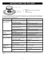
USING THE BURNERS
The silk-screen V\PEROVprinted on the side of the
knob indicate the correspondence between the
knob and the burner.
Automatic start-up with valves
Turn the corresponding knob anticlockwise up
to the maximum position (large flame, fig. 1) and
press the knob.
Once the burner has been started up, keep the
knob pressed for about 6 seconds.
ATTENTION: the triple ring burner switches on
only RQ the maximum flame position
Notice
–– When the equipment is not working, always
check that the knobs are in the closing position
(see fig.1SDJH).
–– If the flame should blow out accidentally, the
safety valve will automatically stop the gas
supply, after a few seconds. To restore operation,
set the knob to the lighting point (large flame, fig.
1) and press.
–– While cooking with fat or oil, pay the utmost
attention as these substances can catch fire
when overheated.
–– Do not place unstable or deformed pots on the
burner, so as to prevent them from overturning or
overflowing.
–– Handles should be turned away from the front of
the bench to avoid accidents.
–– When the burner is started up, check that the
flame is regular and, before taking pots away,
always lower the flame or put it out.
Using the burners
In order to obtain the maximum yield without
waste of gas, it is important that the diameter of
the pot is suitable for the burner potential (see the
following table), so as to avoid that the flame going
out (fig. 2SDJH).
Use the maximum capacity to quickly make
liquids reach boiling temperature, and the reduced
capacity to heat food or maintain boiling. All of the
operating positions must be chosen between the
maximum and the minimum ones, never between
the minimum position and the closing point.
The gas supply can be interrupted by turning
the knob clockwise up to the closing position. If
there is no power supply, it is possible to light the
burners with matches, setting the knob to the startup point (large flame, fig. 1SDJH).
BURNERS
Power (MJ/h)
NG
LPG
Ø of
cookware (*)
Auxiliary
3,4
3,4
10 - 14 cm
Semi-rapid
6,3
5,6
16 - 18 cm
Rapid
11,5
9,6
20 - 22 cm
Triple crown
13,0
12,0
24 - 26 cm
Double crown
10,3
9,6
24 - 26 cm
(*) For cookware with diameter 120mm or
below use mini-trivet supplied, refer fitment
instructions on page 13.
4
INSTRUCTIONS FOR THE USER
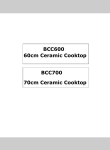
1Burner
2
Flame safeguard sensor (where fitted)
3Injector
4
Ignition spark plug
If you have a problem with the cooktop, check the table below. You may be able to solve the problem and
this will save you from paying for a service call. You will have to pay for a service call even in the warranty
period if the problem is one listed below
FAULT
POSSIBLE CAUSES
REMEDY
Burner will not light
Knob not held down long enough in Repeat lighting procedure and hold knob
even though the LJQLWLRQ ‘High’ position for flame safeguard down for 6 seconds in ‘High’ position (refer
VSDUNis working.
(where fitted) to engage
page 3)
Gas supply valve turned off
Turn on gas supply to appliance
Wrong knob turned
Ensure the knob you are turning
corresponds to the burner you want to light
%lockage in ignition area
Ensure that ports in ignition area are clean
and dry
Ignition spark plugs wet or dirty
Dry or clean ignition spark plugs
No spark is obtained
when control knob is
activated
Electricity supply is disconnected or
switched off"
Switch on electricity or check fuses
Ignition spark plugs wet or dirty
Dry or clean ignition spark plugs
Flames uneven or
tending to lift
Flame ports blocked or wet
Clean or dry flame ports
Burner incorrectly fitted
Ensure this component is fitted correctly
Flames not staying on
when knob released
Knob not held down long enough
in ‘High’ position for flame safeguard
(where fitted) to engage
Repeat lighting procedure and hold knob
down for 6 seconds in ‘High’ position
(refer page 3)
Knob not set between ‘High’ and
‘Low’
Knob MUST be set between these
positions
Dirt or spillage on flame safeguard
sensor (where fitted)
Clean flame safe guard sensor tip
Low heat, slow
cooking
Incorrect cooking pot or pan being
used
Refer to table page 3
Benchtop or knobs
overheating
Incorrect cooking pot or pan used
Check table on page 3 for correct pot or
pan to be used
Pot or pan not located on burner
properly
Ensure pot or pan is centrally located
on burner
If the above points have been checked and there is still a problem with the cooktop, please call the Service
Centre.
5
INSTRUCTIONS FOR THE USER
CLEANING
Wash with warm soapy water and rinse with clean water.
Where the stainless steel has become extremely dirty
with signs of surface discolouration (due to periods of
neglect or misuse) use a stainless steel cleaner
DO NOT use abrasive scourers or steel wool. When
removing these stains be sure to follow the polish of
brushing lines.
Before any operation, disconnect the appliance from
the electrical supply.
Don’t use a steam cleaner for the cleaning the hob.
It is advisable to clean the appliance when it is cold.
Enamelled parts
The enamelled parts must be washed with a sponge and
soapy water or with a light detergent.
Do not use abrasive or corrosive products.
Do not leave substances, such as lemon or tomato juice,
salt water, vinegar, coffee and milk on the enamelled
surfaces for a long time.
Burners and racks
These parts can be removed to make cleaning easier.
The burners must be washed with a sponge and soapy
water or with a light detergent, wiped well and placed in
their housing perfectly. Make sure that the flame-dividing
ducts are not clogged. Check that the VHQVRU of the safety
valve and the start-up electrode are always cleaned, so
as to ensure optimum operation.
Stainless steel parts
Stainless steel can be stained if it remains in contact with
highly alkaline water or aggressive detergents for an
extended period of time.
All grades of stainless steel may stain, discolour or
attain an adhering layer of grime in normal operation.
To achieve optimum surface appearance stainless steel
must be kept clean regularly using the following cleaning
procedures, this ensuring good performance and long
service life.
Gas taps
The possible lubrication of the taps must be carried out by
authorised personnel, exclusively.
In case of hardening or malfunctions in the gas taps,
SOHDVHFRQWDFWWKH&XVWRPHU&DUH'HSDUWPHQW
INSTRUCTIONS FOR THE INSTALLER
Important notice:
The operations indicated below must be followed by authorised personnel exclusively, in
conformity with the regulations in force.
The manufacturing firm refuses all responsibility for damages to people, animals or things,
resulting from the failure to comply with such provisions.
This appliance shall be installed only by authorised persons and in accordance with the
manufacturer’s installation instructions, local gas fitting regulations, municipal building codes,
electrical wiring regulations, and any other statutory regulations. For Australia and New Zealand
this appliance must be installed by an authorised person in compliance with as/nzs 5601.1 Gas
installations part 1: general installations, and as/nzs 5601.2 Gas installations part 2: lp gas
installations in caravans and boats for nonpropulsive purposes. For outside of Australia/New
Zealand refer to the relevant installation code for gas appliances in your country.
INSTALLATION
–
–LPG conversion kit
–– 1 Universal LPG sticker
–– 4 or 5 injectors
Additional accessory for cooking with vessels
diameter 120mm or below
–– 1 mini trivet
The installation kit contains the following:
–– 1 natural gas regulator
–– 1 elbow
–– 1 manifold
–– 2 fibre sealing washers
–– 4 brackets for assembly
–– 4 bracket screws
–– 1 pack of cooktop to benchtop seals
–– 1 duplicate rating label
Installing the top
The appliance is designed to be embedded into heatresistant benchtop capable of withstanding 85°C.
6
INSTRUCTIONS FOR THE INSTALLER
Adjacent walls, cupboards and protection for
combustible materials.
Depending on the type of mounting surface, the
suitable type of mounting hook is supplied (hook A
or hook B).
For the installation proceed as follows:
–– Remove all loose components from the top.
–– Turn the appliance upside down lay it's edges on
foam packaging blocks to prevent damage to the
ignition spark plugs and lay the seal S along the
external border (fig. 5SDJH).
–3lace
–
the cooktop in the DSHUWXUHhole PDGH
in the ZRUNWRS furniture, then fasten it with
the screws and fastening brackets supplied
(fig.6SDJH).
Ensure that the appliance is installed in
accordance with clauses 6.2.5 and 6.10.1.1 of AS/
NZS 5601.1, or clauses 6.9.1 and 6.9.5 of
AS/NZS 5601.2 with regard to clearances
to combustible surfaces and materials, and
clearances to rangehoods and exhaust fans.
Clearance of 200mm from the periphery of burners
to vertical combustible surfaces is required.
Clearances to combustible surfaces may be
reduced only if combustible surfaces are protected
in accordance with clause 6.10.1.2 of AS/NZS
5601.1, or clause 6.9.2 of AS/NZS 5601.2.
WARNING: Failure to fix the cooktop to the bench
could result in loosening of the gas connection
through movement of the cooktop and a gas leak
may result.
A duplicate rating label is included with these
instructions. Ensure this is attached to a readily
accessible surface, so that the cooktop can be
easily identified in the case of a service call.
The equipment must not be installed near
inflammable materials, such as curtains,
cloths,etc. Make a cut out in the benchtop, with
the dimensions indicated below (see fig.3,
page 10) at a distance of at least 50 mm
from the appliance boarder to the adjacent walls.
MODEL
L (mm)
P (mm)
D (mm)
BP64S
560
480
55
BP75S
625
480
55
BP95S
805
480
55
Installation room
This appliance is not provided with a device for
exhausting the products of combustion.
Therefore, it is necessary to discharge these
outside.
The room where this appliance is installed
must have a natural air inflow, so as to ensure
a regular gas combustion and room ventilation:
the necessary air volume must not be lower than
20m3.
Air must come from permanent openings made on
the room walls that communicate with the outside.
The section of these openings shall correspond to
at least 200 cm2.
Any possible wall unit over the cook-top must be
placed at a distance of at least 760 mm from the
top.
IMPORTANT:
A separation panel at least 10mm from the
bottom of the cooktop must be included during
installation to prevent access to the underside
of the appliance. This panel can be made of any
non-combustible rigid material. Refer (fig. 4).
If the hob is going to be installed on the top of an
oven, precautions must be taken to guarantee an
installation in accordance with current accident
prevention standards. Pay particular attention to
the position of the electric cable and gas pipe: they
must not touch any hot parts of the oven.
Moreover, if the hob is going to be installed on
the top of a built in oven without forced cooling
ventilation, proper air vents must be installed to
guarantee an adequate ventilation, with the lower
air entering with a cross section of at least 200cm2,
and the higher air exiting with a cross section of at
least 60 cm2.
OPERATION ON N.G / L.P.G.
Regulator
An appliance regulator is provided. The regulator
must be positioned so that the pressure test nipple
is accessible when the appliance is installed.
Connect the gas supply to the 1/2" B.S.P. internal
thread inlet of the regulator. Refer to page 8 for
connection point position.
Regulators are supplied pre-adjusted and
configured by the component maker for use with
Natural Gas. The appliance installer is not required
to make an adjustment to obtain the correct outlet
pressure setting.
An arrow on the base of the regulator indicates
the direction of gas flow when the inlet and outlet
of the regulator is orientated correctly. When the
regulator has been fitted check for leaks from the
connections with soapy water.
Fastening the top
Every cook-top is equipped with a special washer.
A set of hooks is also supplied for mounting the
cook-top.
7
INSTRUCTIONS FOR THE INSTALLER
Gas Connection
sealing compound.
The inlet of the regulator is a ½” parallel thread and
is connected to consumer piping or hose assembly.
Regulators are supplied pre-adjusted and
configured by the component maker for use with
Natural Gas.
The appliance installer is not required to make an
adjustment to obtain the correct outlet pressure
setting.
An arrow on the base of the regulator indicates the
direction of gas flow when the inlet and outlet of the
regulator is orientated correctly. When the regulator
has been fitted check for leaks from the connections
with soapy water.
This appliance is supplied for use with Natural
Gas. However, it can be converted for use with
LPG. Refer to LP conversion chapter.
Supply pipe sizing
The total hourly gas consumption for the appliance
is shown on the data label. The required supply
pressure (i.e. at inlet to appliance regulator) for
each gas type is shown on the data label, and
given in page "TECHNICAL CHARACTERISTIC
TABLES". Use this information in conjunction with
the length of run, number of elbows, tees and
bends, the available service pressure and the
supply requirements of other installed appliances
to determine a suitable pipe size. For assistance
in this matter refer to the appropriate section of the
Installation Code AS5601.
Checking the gas supply
1. Check the manometer zero point is correct.
2. Connect the manometer to the cooktop
pressure point. This is located on the
regulator.
3. Turn on the gas supply and electricity and try
to ignite the gas. NOTE! lt will take additional
time to light the gas for the first time as air
needs to be purged from the pipes.
4. With the appliance operating check the outlet
pressure
•
when all burners of the appliance are
operating at maximum,
•
when the smallest burner of the appliance is
operating at minimum.
Under these conditions the outlet pressure should
not vary from the nominal outlet pressure of
1.00kPa by more than ± 0.20kPa
An AGA certified class B or D flexible connection
may be used to connect the cooktop in accordance
with the AS5601 and in particular section 4.8.
Where a hose assembly is used and the cooktop
is in the installed position, the hose assembly shall
be suitable for connection to a fixed consumer
piping outlet located at a point 800 - 850mm above
the floor and in the region outside the width of the
appliance to a distance of 250mm. The point of
connection to consumer piping must be accessible
with appliance installed.
Elbow positioning
It is possible to reposition the elbow if required by
loosening the locking nut and elbow by using two
spanners. Re-tighten the entire assembly after the
elbow has been repositioned. When fitting elbow to
appliance, ensure that the sealing washer is fitted.
I f t he r eg u l a t o r a p p e a r s t o n o t p e r f o r m
satisfactorily, then check the following points:
1. If the outlet pressure is consistently too low
then the inlet pressure may be too low and
adjustment of an upstream regulator may be
needed, or an upstream regulator or valve
with insufficient flow capacity may be present
in the gas supply line. If this is suspected then
it may be necessary to repeat fhe checks
whilst measuring both the inlet and outlet
pressure to determine if the inlet pressure is
in the range 1.13 - 5kPa.
2. Check that the regulafor has been fitted to the
gas supply line in the correct orientation, the
arrow on the base of the body indicates the
direction of gas flow.
Once these checks have been completed, if the
regulator still fails to perform in a satisfactory
manner it should be replaced.
Regulator
An appliance regulator is provided. The regulator
must be positioned so that the pressure test nipple is
accessible when the appliance is installed. Connect
the gas supply to the ½” B.S.P. internal thread inlet
of the regulator. Refer page 10 for connection point
position.
Assembly of Regulator
The assembly of the regulator to the cooktop
manifold is achieved via the elbow union and
sealing washersupplied.
The ½” parallel thread connects to the manifold, and
the sealing washer is placed between the manifold
end and the flat face on the elbow.
The ½” tapered thread connects to the outlet of the
regulator, and is sealed on the thread using
approved thread sealing tape or approved thread
8
INSTRUCTIONS FOR THE INSTALLER
Adjusting the burners
The lowest flame point must always be properly
adjusted and the flame must remain on even if
there is an abrupt shift from the maximum to the
minimum position.
If this is not so, it is necessary to adjust the lowest
flame point as follows:
–– start the burner up
–– turn the tap up to the minimum position (small
flame)
–– remove the knob from the tap rod
–– introduce a flat-tip screwdriver in the hole F of the
tap (fig. 8) and turn the by-pass screw up to a
proper adjustment of the lowest flame point.
As regards U-LPG gas burners, the by-pass
screw must be tightened completely.
Electrical connection
The appliance is supplied with a standard 10
Amp service cord terminated by a 3-pin plug for
connection to a standard household socket. The
electrical supply is required to power the electronic
ignition system.
NOTE: It will be necessary for servicing purposes
to disconnect the electrical power supply. The
power point should therefore be accessible after
the appliance is installed, as specified in the local
wiring regulations.
TESTING APPLIANCE OPERATION
After installation the installer must fully test the
appliance and ensure it operates correctly before
handing it over to the customer.
GAS CONVERSIONS AND ADJUSTMENTS
Data Label
This appliance is suitable for Natural Gas and
Universal LPG; ensure that the available gas supply
matches the Data Label.
When converting from Natural Gas to Universal
LPG ensure that the NG regulator is removed
and replaced with the Test Point Assembly. An
AGA Approved gas regulator suitable for a supply
pressure of 2.75kPa should be part of the gas
tank supply and the test point pressure should be
adjusted to 2.75kPa.
MAINTENANCE
Maintenance Schedule
No regular maintenance is required for the FRRNWRS
except cleaning.
Replacing the power supply cable
If the power supply cable should be replaced,
it is necessary to use a cable with a section of
3x0.75mm2, type H05VV-F or H05RR-F, complying
with the regulations in force.
The connection to the terminal board must be
effected as shown in fig.9 - 9/A:
Replacing the injectors
If the equipment is adjusted for a type of gas that is
different from the one available, it is necessary to
replace the burner injectors.
The choice of the injectors to replace must be
made according to the table of the “technical
characteristics” as enclosed.
Act as follows:
–– remove the racks and burners.
–– by means of a straight spanner L, unscrew
the injectors U (fig. 7) and substitute it with the
corresponding one.
–– tighten the injectors strongly.
brown cable L
blue cable N green-yellow cable
After changing the injectors, it is necessary to
eliminate residual natural gas in the system.
To do this you have to turn to the maximum
position then press the knob of each burner and
wait few seconds.
9
(live)
(neutral)
(ground)
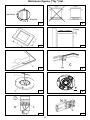
Reference figures ("fig.") list
OFF
MAXIMUM
MINIMUM
1
2
3
4
5
6
F
7
8
9/A
9
10
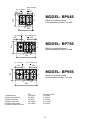
Gas Connection
Electrical Supply
Cord
207
510
105
2
2
5
3
MODEL: BP64S
Depth of cooktop casing
from benchtop surface : 44 mm
8
590
Gas Connection
Electrical Supply Cord
270
183
510
2
1
MODEL: BP75S
2
Depth of cooktop casing
from benchtop surface : 44 mm
4
3
Gas Connection
750
8
Electrical Supply Cord
295
280
2
510
1
4
2
3
MODEL: BP95S
Depth of cooktop casing
from benchtop surface : 44 mm
8
890
NGUniversal LPG
1 Rapid burner 11,5 MJ/h
9.6 MJ/h
2 Semi-rapid burner
6.3 MJ/h
5.6 MJ/h
3 Auxiliary burner
3.4 MJ/h
3.4 MJ/h
4 Triple ring burner
13.0 MJ/h
12.0 MJ/h
5 Double ring burner
10.3 MJ/h
9.6 MJ/h
8 Control knob for burner
11
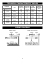
TECHNICAL CHARACTERISTIC TABLES
GAS
NORMAL
PRESSURE
INJECTOR
DIAMETER
TAPE BY
PASS
DIAMETER
KPa
1/100 mm
1/100 mm
Universal LPG
2.75
85
40
9.6
Natural
1.00
155
Adjust.
11.5
BURNERS
N°
DESCRIPTION
NOMINAL
HEAT INPUT
(MJ/h)
1
RAPID
2
SEMI-RAPID
3
AUXILIARY
4
TRIPLE
CROWN
Universal LPG
2.75
95
60
12.0
Natural
1.00
160
Adjust.
13.0
5
DOUBLE
CROWN
Universal LPG
2.75
85
60
9.6
Natural
1.00
145
Adjust.
10.3
Universal LPG
2.75
65
31
5.6
Natural
1.00
110
Adjust.
6.3
Universal LPG
2.75
52
27
3.4
Natural
1.00
80
Adjust.
3.4
WIRING DIAGRAM
MODEL: BP64S
IGNITION
GENERATOR
MODEL: BP75S / BP95S
TRIPOLAR
TERMINAL
IGNITION
GENERATOR
MICRO-UNIT
MICRO-UNIT
12
TRIPOLAR
TERMINAL
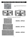
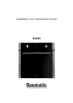
INSTRUCTIONS FOR USING THE MINI TRIVET
The mini-trivet included with this cooktop is to be
used for cooking vessels of diameter 120mm or
smaller
Incorrect fitment
Correct fitment
Examples of positioning of mini-trivet
MODEL: BP64S
MODEL: BP75S
MODEL: BP90S
13
IMPORTANT: If your appliance appears not to be
operating correctly, then you should disconnect it
from your mains supply and then contact the
Customer &DUH Department.
DO NOT ATTEMPT
YOURSELF.
TO
REPAIR
THE
APPLIANCE
Please note that if an engineer is asked to attend whilst the product is
under guarantee and finds that the problem is not the result of an
appliance fault, then you may be liable for the cost of the call out charge.
The appliance must be accessible for the service technician to
perform any necessary repair. If your appliance is installed in
such a way that a service technician is concerned that damage will
be caused to the appliance or your kitchen, then he will not
complete a repair.
This includes situations where appliances have been tiled in,
sealed in with sealant, have wooden obstructions placed in front
of the appliance, like plinths. Or any installation other than the
one specified by the manufacturer has been completed.
IMPORTANT: The manufacturer operates a policy of continuous
improvement and reserves the right to adjust and modify its
products without prior notification.
15
Think Appliances Pty Ltd.
416-424 Barry Rd
Coolaroo VIC 3048
Sales Telephone
1300 132 824
Service Telephone
1800 444 357
Website
www.thinkappliances.com
Applico Ltd.
P.O. 92900
Onehunga, Auckland 1061
New Zealand
Website
www.baumatic.co.nz
United Kingdom
Baumatic Ltd.,
Baumatic Buildings,
6 Bennet Road,
Reading, Berkshire
RG2 0QX
United Kingdom
Sales Telephone
(0118) 933 6900
Website:
www.baumatic.co.uk