1
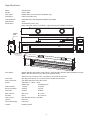
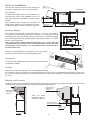
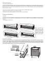
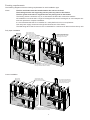
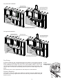
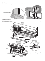
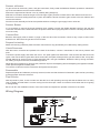
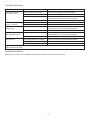
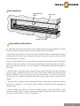
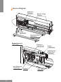
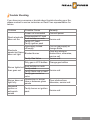
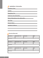
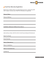
Flameboyant
By Real Fires
Gas Fire Installation Guide
Installation into Timber Framing
illusion 1800
Retain these instructions until installation is complete
IMPORTANT NOTES:
THIS APPLIANCE MUST BE INSTALLED BY A SUITABLY QUALIFIED PERSON IN ACCORDANCE WITH LOCAL
CODES AND AS 5601 / NZS 5261
THIS IS PRIMARILY A DECORATIVE APPLIANCE AND HAS NOT BEEN DESIGNED AS A SPACE HEATER
THIS APPLIANCE HAS BEEN TESTED TO AS 4558-2000
DO NOT OPERATE THIS APPLIANCE WITHOUT READING AND UNDERSTANDING THESE INSTRUCTIONS
FIRST
THIS APPLIANCE IS DESIGNED FOR INSTALLATION INTO A TIMBER FRAMED CONSTRUCTION
THIS APPLIANCE MUST INSTALLED USING AN APPROVED TWIN SKINNED B-VENT FLUE SYSTEM
THIS APPLIANCE MUST BE INSTALLED INTO A WELL VENTILATED ROOM IN ACCORDANCE WITH AS 5601/ NZS
5261
THIS APPLIANCE IS DESIGNED FOR INDOOR INSTALLATION ONLY; NOT TO BE INSTALLED OUTDOORS
REAL FIRES IS NOT RESPONSIBLE FOR INCORRECT OR IMPROPER INSTALLATIONS
ALL INSTALLATIONS MUST BE CERTIFIED
BE SURE TO FILL IN INSTALLER DETAILS SECTION OF THE USER GUIDE BEFORE SIGNING OFF THE
INSTALLATION
Some drawings in this guide use a smaller version of this fire for pictorial purposes only.
Table of Contents
IMPORTANT NOTES:
Specifications:
Notes on Installation:
Gas Supply Electrical Supply
Clearances
Hearths
Mantles and Recesses
Flue requirements
Firebox installation:
Options Insulation kit fitting
Framing requirements
Top Fixing
Wall Lining
Commissioning:
Remove reflectors
Remove Burner
Connect Gas
Prepare for testing
Check Pressures
Reassemble
Final Checks
Wiring Diagram
Trouble Shooting
Installation Notes
2
4
5
5
5
5
5
5
6
6
6
6
7
8
9
9
10
10
10
10
10
10
10
10
11
11
Contact Details
12
Specifications:
Make:
Model:
Gas Types:
Description:
Test standards:
Flameboyant
illusion 1800
Natural Gas, ULPG, Propane (Australia only)
Indoor Decorative Fire
NZS 5262:2003, AS 4558-2000 AS/NZS 3100:2002
Approval No:
Dimensions:
7736
All dimensions are in mm
Note: Left hand version of fire shown, right hand version available if required
Power
Inlet
2174
1469
210
469
1825
453
50
297
260
Gas Inlet
Flue Spigot:
Natural draught flue system using 2 Ø150 ~ 200 twin skin flue with optional adaptor to single Ø200 ~250 twin skin flue (inner flue to be stainless steel)
Minimum of 2.4 metres of flue, 3.6 metres if off-set bends are used
Flue Cowl: two approved 150 mm or one 200 mm Flue Cowls must be used
Gas Connection:3/8” BSPF Gas Flare onto gas control
Power: 230/240V a.c. 50hz, 1 Amp
Natural gas
ULPG/Propane
Inlet Pressure:
1.0 kPa 2.75 kPa
Burner Pressure:
0.8 kPa
1.9 kPa
Gas Rate: 34 MJ/h34 MJ/h
Main Injector:
Ø 3.0 mm
Ø 1.8 mm
Aeration
None
Ø 10.00 mm
Gas Control: SIT 840 with SIT 579. 402 DBC Ignition:
Electronic
Flame Monitoring:
Flame rod
Control:
Isolating switch
Notes on Installation:
All notes refer to left hand version of fire and must be
reversed if a right hand version is being installed
Pow
appr er lead 1
ox
.8 M
etre
s
Glass Side
A suitable gas supply needs to be provided to the
Left hand rear corner of the installation cavity. The
pipe sizing should be calculated to supply at least
40 MJ/h
Allow sufficient pipe to make the connection as
shown below (Refer to the Commissioning section
for details on gas and power connection, page 10)
103 ±5
Gas Supply
This bend is
required to
clear gas control
Open Side
400 ±10
To Fire/s
Electrical Supply
The Firebox is supplied with a power lead approx. 1.8 m long. This needs to
be connected to an isolating wall switch, provided by an electrician, located
preferably to the right of the Firebox, facing into the room, not inside the framing
cavity. This supply is used to isolate all power for the electronic fires or to control
the fan in the manual fires.
Note: if the power is disconnected through power cut or other event and
reinstated with the isolating switch in the ON position, the fire will start
automatically. To prevent this it is recommended that a latched relay is
used as shown here.
The power cord is designed for a 230/240V a.c. 10 amp supply.
Electrical connection must comply with AS/NZS 3000.
NO
COMMON
P
N
E
Mains Supply
NC
10 Amp Relay
500 m
m
Min
m
0m
50 in
M
Clearances
Hearths
10
Min00 mm
10
0
Mi 0 m
n
m
The fire must be installed with the shown minimum clearances to
combustible materials
Although a hearth is not required, if the fire is installed within 500
mm of the floor, Real Fires does recommend that protection is given to any combustible flooring directly in front of the
fire. The fire produces a large amount of radiant heat and this might cause damage to carpets and furnishings that are
too close.
Mantles and Recesses
A timber mantle may be installed above this appliance but must be within the grey area shown here. If the fire is to be
installed into a recess the recess must comply with the following limitations
Recess must not
extend beyond
this area
45°
X
Mantle must not
extend beyond
this area
Mantle
Wall
300
X
Note: The same
limitations apply to
the sides of the fire
45°
Fire Proof Board for
minimum height of 300mm
Fire Proof
Board
Top Trim
100
Flue requirements
Only used an approved cowl
The fire is fitted with two Ø150~200 flue spigots and standard flue components should be used. A Y piece collector is
available from Real Fires that allows the two flues to be joined into one Ø200~250 to be finished using standard twin
skin flue and flue cowl. It is recommended that the 150~200 mm flue is taken vertically as high as practicable before
joining using the Y piece.
The minimum total flue height is 2.4 metres, providing the flue is straight without offsets.
Offsets can be used on flues over 3.6 metres in height.
The flue and cowl must be installed in accordance with AS 5601/NZS5261
Firebox installation:
Options
The illusion fire can be installed in 4 different ways. The basic fire is supplied ready for installation as a fully open fire
where the fire is open to the front and the glass sides are to the right and back. It is also available as a right hand fire if
required.
The installations options are:
Fully Open (left hand version)
Corner Unit
Note: All fires are
shown with the open
side foremost and glass
panels to the back and
right hand end. Even
with the insulation kits
installed, the glass
panels remain in place.
Fully Enclosed
Through Wall
Insulation kit fitting
Insulation kits are available for conversion these options and will require fitting before the installation continues. Unseen
trims may need to be cut away to make fitting of the wallboard easier and tidier, the trims to cut will depend on the
installation option. Make sure that you have clearly identified the panels that are to be cut before proceeding. It
may be easier to fit the insulation panel prior to making any cuts. Be sure to remove all the protective plastic
from any panels that will be covered by the insulation panels.
Relieve corner of
unseen trim to allow wall
lining to fit behind the trim
Align faces
and edges
DO NOT
CUT THE SEEN
TRIM PANELS
Drill and rivet
in place (4 places)
Cut here for
Through Wall and
Fully Enclosed
Cut here for
Through Wall and
Corner Unit
Framing requirements
The following diagrams show the framing requirements for each installation type.
Notes:
The flue and firebox must be installed before the wall can be lined.
The framing must be self supporting and not place any load on the firebox.
The flue system must also be supported and not placing load on the firebox.
The framing shown is indicative only is not intended to illustrate the construction method.
All installations are shown with 1 length of rectangular flue and the rectangular to round adapter and does not represent a complete installation.
It is recommended that the fire is installed on a solid platform but is not a requirement
Gas and power supply must enter through the left hand end of the firebox
The Wall lining above the fire must be non combustible for a minimum off 300 mm above the top trim
Fully Open installation
There must be a clear
path for the flue to pass
Allow at least
20mm gap for
power and gas
250
Min
Min
2183
1000
Min
468
o
cladd ver
ing
1000
Recommended
Minimum
463 Min
715
Flue is shown with optional flue
gather and 200~250mm top flue
section. Alternative is to run two
flues throught to termination
These sections must be fully
supported from above and
not place any load on the fire
Refer to
note on
top fixing
295
min over
cladding
Platform
recommended
Wall lining above the top trim must be
non-combustible for at least 300mm (wall lining
can only be fitted after firebox is installed)
Corner installation
Allow at least
20mm gap for
power and gas
There must be a clear
path for the flue to pass
26
3
M
in
250
Min
Min
1000
2183
Min
322 Min
over
cladding
468 Min
over
cladding
Platform
recommended
1000
recommended
minimum
463 Min
715
Flue is shown with optional flue
gather and 200~250mm top flue
section. Alternative is to run two
flues through to termination
Refer to
note on
top fixing
Wall lining above the top trim must be
non-combustible for at least 300mm (wall lining
can only be fitted after firebox is installed)
Fully Enclosed installation
There must be a clear
path for the flue to pass
3
26
m
Flue is shown with optional flue
gather and 200~250mm top flue
section. Alternative is to run two
flues through to termination
in
Allow at least
20mm gap for
power and gas
715
in
M
2
g
3 2 v e r d in
o la d
c
Min
Min
2210
1000
Min
495
Min
1000
recommended
minimum
463
Min
250
Platform
recommended
Refer to
note on
top fixing
Wall lining above the top trim must be
non-combustible for at least 300mm (wall lining
can only be fitted after firebox is installed)
Through Wall installation
This section must be fully
supported from above and
not place any load on the fire
There must be a clear
path for the flue to pass
Flue is shown with optional flue
gather and 200~250mm top flue
section. Alternative is to run two
flues throught to termination
Allow at least
20mm gap for
power and gas
250
Min
715
Min
2210
1000
Min
495
Min
295 Min
over
cladding
1000
recommended
minimum
Platform
recommended
Refer to
note on
top fixing
Wall lining above the top trim must be
non-combustible for at least 300mm (wall lining
can only be fitted after firebox is installed)
Top Fixing
In order to keep the top, unsupported end of the firebox in line with the framing
above, a pair of straps have been provided for fixing to the completed framing. In
some installations the straps may not be the most suitable solution. If this is the
case then use another seismic type strap to hold the firebox fast to the framing. Take
care to make sure that the wall cladding will line up with the inside edge of the trim
panel.
Shown here is the cutout requirement for the straps to be most effective.
Seismic Restraint
There are 4 holes in the base of the firebox to hold the fire in place. Make sure that
the firebox is correctly aligned with where the wall lining will finish before fixing the
firebox in place.
21 from
cladding to back
of support plate
115 Min
Wall Lining
The wall lining above the top trim must be non-combustible for at least 300mm.
Wall Lining fits
behind front edge
of trim
It is recommended that
the plaster coat does not
cover the front trim.
Commissioning:
Refer to the diagram below for part identification (note that the illusion 1000 is shown for the parts diagram but the parts
are the same for this model)
Reflector
Retainer
End
Reflector
Burner Fixing
Screws
Front and Back
Reflectors
Earth Terminal
Spring Washer
and Nut
Burner Pressure
Test Point
Pressure
Adjustment
Power
Connection
Power
Plug
Sparker and
Flame Rod
Assembly
Disconnect the power and gas
supplies before working on the fire
Inlet Pressure
Test Point
Injector
Gas Inlet
Remove reflectors
To gain access to the burner, power, and gas connections, firstly rotate the Reflector Retainer upwards to release the
top of the end reflector and remove the reflector.
Remove the right hand end burner cover by carefully lifting straight up.
Slide the front reflector towards the gas control enough to gain purchase on both ends of the reflector and remove it.
Remove the 2 screws holding the burner in place and slide the burner forward to gain access to the rear reflector and
remove the reflector.
Push the burner assembly as far back as possible without crushing the gas supply hose or wires etc.
Remove Burner
If it is necessary to remove the burner assembly then carefully unscrew the flexible braided hose from the gas inlet
connection and remove the earth lead from the power bracket and unplug the power connector. Carefully lift the burner
out of the cavity.
Connect Gas
Bend the Gas supply tube as shown on page 5, flare and fit to inlet connection. Check for any crimps or kinks in the
braided hose. Reconnect the gas and check for leaks.
Prepare for testing
Make sure that any protective plastic has been removed from any panels likely to be affected by staring the fire.
Check Pressures
With the burner connected and pushed to the back of the firebox, connect a manometer to the burner pressure test
point.
Connect the power supply and switch the fire on. The spark ignition will start within a few seconds and the burner will
ignite. If the burner fails to ignite within about 5 seconds, the spark will stop and the gas will cease to flow. It may take
several attempts to get the burner to ignite especially with a new gas installation. Restart the fire by turning the switch
off, waiting a couple of seconds, and switching back on.
Adjust the burner pressure by removing the protective cap from the adjusting stem and adjusting the regulator beneath.
Check pressure against the data plate.
Turn the fire off and remove the manometer and tighten the test point.
Reassemble
Replace all panels and reflectors previously removed, make sure that the burner is fastened in place and any remaining
protective plastic has been removed.
Final Checks
With all panels in place, check to make sure that the fire is still operating correctly and that the flames are not overly
long or streaky and that there is no soot coming from the flame tips. Listen for excessive noise when the fire is igniting
or extinguishing.
Be sure to fill in the Installation section of the User Guide and explain the operation of the fire to the owner
Wiring Diagram
COLOUR
WHITE
BLUE
BROWN
GREEN / YELLOW
ORANGE
Connector
Plug
5 Amp
MAINS IN
230/240 V a.c.
50 Hz
10 AMP MAX
BRN
BLU
GR85
1 - EMPTY
2 - EMPTY
3 - EMPTY
4 - EMPTY
5 - BLK
6 - BLK
7 - BLK
8 - EMPTY
9 - EMPTY
10 - BRN
11 - BLU
12 - GR
WH
BLU
BRN
GR
OR
GAS CONTROL 12 PIN PLUG
GR
GR
FLAME
OR
WH (HT LEAD)
SPARK
1 GAS CONTROL 12
(SIT840 with 0.579.402 DBC)
10
Trouble Shooting
Problem
Possible Cause
Remedy
Fire does not start
(no spark noise)
Mains Power Disconnected
Check mains supply and isolating switch
Gas Control locked out
Switch Off and On again *
Faulty Spark Electrode
Check HT lead
Check Electrode is not touching the bracket
Faulty control
Service call
Fire is sparking then
stops (no flames)
Air in gas pipe
Purge gas pipes *
Gas supply turned off/empty
Turn on gas supply or change bottles *
Flame starts but spark
keeps going
Faulty flame rod
Check flame rod lead
Check flame rod is not touching the bracket
Wind blowing on burner
Prevent excessive draft on burner
Faulty flame rod
Check flame rod lead
Check flame rod is not touching the bracket
Wind blowing on burner
Prevent excessive draft on burner
Gas Supply turned off or empty
Check gas supply or change/replace bottles
Power supply turned off
Check power is on
Wind blowing on burner
Prevent excessive draft on burner
Spark going but flames
don’t appear to go out
Fire goes out
* If the fire fails to ignite after 3 attempts, turn off the power and gas if possible and arrange a service call or contact
the installer if fire is new.
Installation Notes
Write any comments on the installation here and leave with the owner for future reference.
11
Contact Details
Flameboyant.com.au
Regency Fireplace Products Australia Pty Ltd.
21-23 South Link
Dandenong South
Vic 3175
Australia
Phone 1 800 081 978
Fax 03 9799 7822
Email [email protected]
66300
issue D
12
Installation Guide illusion 1800
By Real Fires
User Guide and Service Manual
Model
Illusion
Thank you for choosing to purchase a Real Fires fire for your home.
Our products are proudly New Zealand Inspired and manufactured
from the finest materials.
This User Guide is designed to familiarise you with the fire, its features,
operation, and care. We know you will get many years of enjoyment
from your Real Fires fire.
Congratulations on your purchase.
Warmest regards,
Ali Fenton
Company Director
User Guide and Service Manual
Flameboyant
By Real Fires
Illusion 1800
Contents
Important Notes ��������������������������������������������������������������������������������������������4
Specifications�������������������������������������������������������������������������������������������������4
Fire Features����������������������������������������������������������������������������������������������������5
Operation Instructions�����������������������������������������������������������������������������������5
Safety���������������������������������������������������������������������������������������������������������������6
Cleaning���������������������������������������������������������������������������������������������������������6
Warranty Statement��������������������������������������������������������������������������������������7
Conditions of warranty����������������������������������������������������������������������������������7
Service�������������������������������������������������������������������������������������������������������������7
Servicing Requirements���������������������������������������������������������������������������������8
Service Instructions�����������������������������������������������������������������������������������������8
Service Diagram�������������������������������������������������������������������������������������������10
Trouble Shooting������������������������������������������������������������������������������������������11
Installation Information��������������������������������������������������������������������������������12
Service Record���������������������������������������������������������������������������������������������12
Real Fires Warranty Registration�����������������������������������������������������������������13
Contact���������������������������������������������������������������������������������������������������������16
Important Notes
This appliance has been designed in accordance with AS 4558-2000
and NZS 5262:2003
Do not operate this fire without reading and understanding these
instructions.
Please keep these instructions for future reference.
FOR YOUR SAFETY:
Do not place articles on or against this appliance.
Do not hang clothing or flammable materials on this appliance.
Do not use or store flammable material near this appliance.
Do not spray aerosols in the vicinity of this appliance.
Ensure that children are supervised when near the operating
appliance.
WHAT TO DO IF YOU SMELL GAS
•
Do not try to light any appliances
•
Do not touch any electrical switches; do not use any phone in your building
•
Immediately close the shut-off valve at the gas bottles
•
Call a technician
The Flameboyant Illusion gas fire is designed to bring a warmth and
ambiance to your entertainment areas. The electronic controls mean
simple, reliable operation wherever it is required.
Please take some time to read these instructions and familiarise yourself
with its features and operations so that you will get the most out of your
fire.
Specifications
Make
Real Fires
Model
Illusion 1800
Available Gas Types Natural Gas and LPG
Power Consumption 230/240 V a.c. 50Hz 1 Amp
Control Type
Electronic
Gas Rate34 MJ/h
Fire Features
Heat Reflector
Panel
Outer Trim
Burner
Glass Panels
Operation Instructions
To operate your fire for the first time, ensure that the gas supply is on and
that the fire has been tested and certified by the installer.
Your Illusion gas fire should have been installed with a separate isolating
wall switch mounted on a nearby wall and may also have a start button
connected to a relay*.
Turn the wall switch to the on position and press the start button (if fitted).
Within a few seconds you will hear a sparking sound and gas will start to
flow through the burner. Once a flame is established the spark ignition
will stop.
If the fire fails to ignite within about 5 seconds, the gas will stop flowing
and the gas control will lock out. This is most likely when the fire has just
been installed or has not been used for some time. Turn the wall switch
off and the on again and press the start button and the cycle will start
again.
If the fire fails to ignite after 4 attempts then consult the trouble shooting
section on page 11 or contact your installer or Real Fires to arrange a
service call.
* Note: Unless your fire has been installed using a latched relay, it will
automatically start if, after a power outage, the power is re-connected
and the wall switch is in the on position.
Safety
Real Fires are factory tested and the installation should have been
tested by the installer. You should not experience any odour from your
fire other than an initial burn off smell the first time it is used.
Should any additional odour be noticed, turn off the gas supply and
arrange for a gas fitter to make a service call.
Your Real Fire has a flame failure safety system which ensures that
in the event of an ignition failure, gas supply failure, or flame being
extinguished for any reason, the fire will shut down. The fire will attempt
to restart automatically. If the fire fails to re ignite, then the fire will ‘lock
out’ and will need to be reset manually by switching the wall switch off
and on again to restart the ignition sequence.
Wait at least 10 seconds before attempting to restart the fire and if the
fire fails to ignite after three attempts, then turn off the power and refer
to the Troubleshooting section on page 11 or consult a technician.
Real Fires burn with a real flame and as such there are considerations to
be made to ensure the safety of children and the infirm.
Do not place furniture and other objects within one metre of the fire,
do not drape clothes or any other combustible materials in front of the
fire.
Cleaning
Regular cleaning of your Real Fire is important to keep it looking its best
and operating at its peak. Some points on cleaning:
•
It is important to keep the burner free from debris such as dust,
insects and anything else that could cause a blockage. Carefully
use a vacuum cleaner to clean the gap between the two glass
panels that make up the burner.
•
The burner and glass panels can be cleaned using household glass
cleaners but apply by cloth rather that by spraying directly onto the
burner. Do not spray cleaners onto or around the burner as the liquid
can get between the glass panels and cause water spotting.
•
The stainless steel reflectors and trims can be cleaned using standard
household stainless steel cleaners. Take care not to scratch the steel
or spray cleaners onto the burner
When to call for Service
•
If soot starts to form on any of the panels (trim or glass).
•
If you can smell gas, whether the fire is going or not (there could be
a small smell of gas as the fire is going through the ignition sequence
but this should stop once the fire has started).
•
If there is excessive noise or explosive ignition as the burner lights, this
could be due to blocked burner ports.
•
If the flames change shape or colour. Under normal operation the
flames will be a bright, luminous, yellow colour. If it becomes a dark,
streaky, orange colour, or a very blue colour, this could indicate a
problem.
Warranty Statement
•
Two year warranty on Parts and Labour
Conditions of warranty
Labour warranty includes vehicle travel cost up to 30 km from place of
purchase or a Real Fires approved service gas fitter.
The maximum period between servicing is two years before warranty is
void.
Warranty does not cover damage caused through incorrect use or
direct exposure to marine environments.
The warranty period is taken from the date of commissioning by the
installer.
Be sure to fill out the Warranty Information section, page 13, for future
reference.
Service
In order for your Real Fire to give years of comfort and enjoyment, Real
Fires recommend that your Real Fire is serviced on an annual basis by a
licensed technician or gas fitter.
Please refer to the back of this User Guide for contact details for Real
Fires.
Servicing Requirements
A regular service must include:
•
Inspect/clean the main burner.
•
Check burner pressures.
•
Check operation of fire.
•
General inspection of the fire.
Service Instructions
Servicing is only to be carried out by a certified gas fitter
Refer to the service diagrams on page 10 for more details.
Disconnect the power and gas supply to the fire before proceeding with
the service.
Service the main Burner Assembly:
• Rotate the reflector retainer to release the top of the end reflector,
rotate the top of the reflector into the firebox and carefully slide
off the burner.
• Slide the front towards the gas burner end of the firebox enough
to get purchase on the end of it and carefully lift it from the
firebox.
• Remove the two burner retaining screws and slide the burner
assembly forward enough to give good access to the rear
reflector and remove the reflector.
• The burner assembly can now be pushed to the back of the
firebox to give better access to the gas control. Remove the
sparker and flame rod assembly and check for any damage or
soot buildup and rectify as required. If more access to the controls
is required then carefully unplug the power connection on the
back wall of the control cavity, disconnect the braided hose at
the front of the burner cavity (at inlet connection)and carefully
remove the complete burner/gas control assembly. (It is a good
idea to lay a cloth over the trim panels to avoid scrtaching them
when removing the burner.)
• Inspect all parts of the gas control and inlet hose. Make sure that
the braided gas hose is not crimped or showing any signs of wear
or deterioration, replace if required.
• Carefully clear the burner by vacuuming between the glass
panels and check for any debris that might be blocking the
burner ports in the base of the burner. If required, carefully undo
the tube connected to the end of the burner and blow through
the injector to clear.
•
If the glass burner panels appear water stained, a clear lint
free cloth wrapped around a piece of thin card can be used
between the panels (DO NOT use anything that could scratch the
glass) avoid using liquid cleaners if possible as this can make any
water spotting worse.
Check the burner pressure:
•
Make sure that the burner has been fully checked and cleaned
and all connections are tight.
•
Push the burner assembly to the back of the firebox and attach a
manometer to the burner pressure test point and make sure that the
manometer tube is well clear of the burner.
•
Reconnect the gas and power supply and light the burner (note
that the burner can be operated for brief periods while push to
the back of the firebox, this allows for safe access to the pressure
adjusting screw). Check that the burner has fully lit and is burning
consistently along its length. If there are any significant disruptions to
the flame, it could indicate a blockage in the burner tube.
•
Leak test any connections that have been broken or disrupted in
any way.
•
Check the burner pressure against the data plate and adjust if
necessary.
•
Remove the manometer and check that the test point is properly
tightened.
Re-assemble the fire:
•
Re-assemble the fire, taking care not to trap or pinch any cables or
gas tubes and test for leaks especially if any gas connections have
been broken.
•
Restart the fire and test for proper operation (ignition, cross lighting,
combustion and flame extinguishing) and fill in the appropriate
section of this booklet.
Power Cord Replacement
If the powercord becmoes damaged, replace only using a manufacturer
supplied part.
Service Diagram
Reflector
Retainer
Burner Fixing
Screws
End
Reflector
Front and Back
Reflectors
Burner Pressure
Test Point
Pressure
Adjustment
Power
Connection
Sparker and
Flame Rod
Assembly
Inlet Pressure
Test Point
10
Injector
Gas Inlet
Trouble Shooting
If you have any concerns or doubts about trouble shooting your fire,
please contact a service technician or Real Fires representative for
advice.
Problem
Possible Cause
Power not connected
Disconnected HT lead
Spark electrode
Soot buildup on rods
does not fire
Faulty HT Lead
Faulty ignition pack
Gas supply turned
off/empty
Electrode
sparks but flame
Blocked burner
does not light
Faulty Gas Valve
Remedy
Connect power
Service call
Turn on gas supply or
change bottle
Clear any obvious
obstructions, otherwise,
service call
Service call
Dirty gas in LPG bottles Change gas bottles
Soot buildup on rods
Burner lights but
Faulty valve
then goes out
Faulty flame rod or lead
Faulty gas control or
valve
Obstruction in burner
Burner does not
tube or between glass
light fully
panels
Abnormal
ignition or
Faulty burner or ignition
extinguish
pack
noises
Service call
Clear obstructions,
otherwise, service call
Service call
11
Installation Information
Installation Date:
Installer:
Registration No:
Serial No (from data plate):
Date of Manufacture (from data plate):
Gas Type:
Owners Name :
Installation Address:
Service
Record
Serviced by
Registration No
Company
Date
Registration No
Company
Date
Registration No
Company
Date
Comments
Serviced by
Comments
Serviced by
Comments
12
Real Fires Warranty Registration
Please fill in details below as requested and return to Real Fires NZ
Ltd in order to ensure your Real Fire Warranty is registered.
Owners Name
Owners Address
Installation Address (if different from above)
SEE INSTALLATION CERTIFICATE FOR DETAILS REQUESTED BELOW
Real Fire Model
Serial Number
Date of Manufacture
Date of Installation
Date of Commissioning
Installed by
13
Fold here, tape and return
Affix
stamp
here
Real Fires NZ Limited
PO Box 100744
North Shore Mail Centre
Auckland 0745
New Zealand
14
Serviced by
Registration No
Company
Date
Registration No
Company
Date
Registration No
Company
Date
Registration No
Company
Date
Registration No
Company
Date
Registration No
Company
Date
Registration No
Company
Date
Registration No
Company
Date
Comments
Serviced by
Comments
Serviced by
Comments
Serviced by
Comments
Serviced by
Comments
Serviced by
Comments
Serviced by
Comments
Serviced by
Comments
15
Contact
Flameboyant.com.au
Regency Fireplace Products Australia Pty Ltd.
21-23 South Link
Dandenong South
Vic 3175
Australia
Phone 1 800 081 978
Fax 03 9799 7822
Email [email protected]
65300
issue B
User Guide illusion 1800