1
User manual
ALFANET 95
with door contact
VDH doc. 080643
Softw.: 011506_ALFANET 95 RTDF-DK
Version: v1.1
File: Do080643.wpd
Date: 12-04-2011
Range: -50,0/+50,0C
* Description.
The ALFANET 95 is a cooling/heating thermostat with various automatic defrost and fan drive facilities.
It can be programmed through the ALFANET PC-INTERFACE on the PC.
* Installation.
On the connection diagram of the ALFANET 95 is shown how the sensor, power supply and relays
should be connected. After the ALFANET 95 has been connected to the power supply a self-test
function will take place, after which the measured temperature will appear in the display.
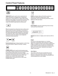
* Operation.
The ALFANET 95 thermostat can be operated by means of four pushbuttons on the front. These
pushbuttons are:
SET
- view / change the set point.
UP
- raise the set point.
DOWN
- lower the set point.
C
- hidden key under the C text.
* Normal operation status.
During normal operation the temperature of the control sensor is shown in the display.
* Viewing the set point.
By pressing the SET key the set point becomes visible. At the same time the decimal point of the righthand display will blink, as an indication that the set point is being read. A few seconds after the SET
key has been released, the set point will disappear and the measured value will be visible again.
1
* Changing the set point.
Press the SET key. The set point appears on the display. Release the SET key. Press the SET key
again. Now the set point can be adjusted with the UP or DOWN keys, the set point can be adjusted.
A few seconds after the keys have been released, the measured value will again appear in the display.
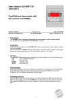
* Status of the Relays.
Press the C key. The three lower segments light up and the
upper vertical segments show the status of the five relays
(see diagram). Relay is active when the segment lights up.
* Start/stop defrost cycle.
The defrost cycle will stop and start automatically by internal parameters. Defrosting can also be done
manually;
Stop:
If defrosting is taking place, defrosting can be stopped manually by pressing the
DOWN and UP keys simultaneously.
Start:
If defrosting is not taking place, then defrosting can be started manually by pressing
the DOWN and UP keys simultaneously.
* Setting internal parameters.
In addition to adjusting the set point a number of internal adjustments can be made, including the
differentials, sensor-offsets, set point range, compressor settings, fan settings and the defrosting
settings.
By pressing the DOWN key for more than 10 seconds the 'internal programming menu' will be
entered. On the left-hand display the upper and lower segment will blink.
With the UP and DOWN keys the required parameter can be selected (see the parameter table).
When the required parameter has been selected, the value of the parameter can be read out by
pressing the SET key. The parameter value can be changed by pressing the UP and DOWN keys. If
no key has been pressed for 20 seconds, the ALFANET 95 will return to it’s normal operation mode.
* Adjusting the sensor.
The control sensor can be adjusted by means of the Offset control sensor (parameter 05).
The defrost sensors can be adjusted by means of the Offsets defrost sensors (parameters 08 and
11). For reading the temperatures of the defrost sensor choose parameters 07 and 10.
Should a sensor of the ALFANET 95 indicates 2C too much, for example. Then the according Sensor
Offset must be lowered by 2C.
* Error messages.
The following error messages may appear in the display of the ALFANET 95:
LO
- Minimum alarm.
Solution E1/E2/E3:
HI
- Maximum alarm.
- Check if sensor is properly connected.
E1
- Control sensor defect.
- Check sensor (1000/25C).
E2
- Defrost sensor-1 defect.
- Replace sensor.
E3
- Defrost sensor-2 defect.
Solution EEE:
EEE - Settings have been lost.
- Program the settings again.
-L-H-
- In case of a short-circuited sensor the error codes E..
and -L- will alternate in the display, indicating a short-circuited sensor.
- In case of a disconnected sensor the error codes E..
and -H- will alternate in the display, indicating a disconnected sensor.
2
* Alarm function
When there is an error message or an alarm, an error code message appears in the display. The
ALFANET 95 remembers this failure message, even if the problem has already been solved. The
failure message can be reset with the SET key. If, after pressing the SET key (=reset alarm) the alarm
is not yet solved, then the ALFANET 95 shows the temperature and error code alternately, if the alarm
has been solved then the error code disappears and the temperature is shown again.
* Fan control settings
The ALFANET 95 has various adjustment possibilities for the Fan. Normally, the fan is always running
unless one of the parameters below is set at 1:
Parameter 20 = 1: Fan switch differential active.
The fan only active if the temperature of the defrost sensor is lower than the control sensor
temperature minus the temperature of the switch differential fan (P21)
{Fan on if Tdefrost < (Tcontrol - Tfandiff.)}.
Parameter 25,26: Fan switching on delay after defrosting.
After defrosting and draining of the humidifier, to prevent the fan from running immediately and thus
blowing warm air into the cell, the following two conditions can be set, i.e.;
a. The fan is blocked until the defrost-sensor measures a temperature that is lower than the set
switching on temperature of the fan (P25).
b. The fan is blocked until the switching on delay of the fan (P26) is over, when the defrost- sensor
reaches the switching on temperature (P25) within the switching on delay, then the fan is
unblocked.
Parameter 22 = 1: Fan is off, when the compressor is off.
The fan is turned off if the compressor is off. This happens with a delay of parameter 23.
* Defrost control possibilities.
The automatic defrost is started on a real-time (P60) base and stops after the maximal defrost time
(P30), or earlier if the defrost sensor has reached the defrost end-temperature (P31). The ALFANET
95 has a number of automatic defrost possibilities that can be set with the following parameters;
Parameter 24 Type of defrost:
The ALFANET 95 has three possibilities for defrosting;
P24 = 0
For defrost only the relay FAN is switched on (natural defrosting).
P24 = 1
For defrosting only the relay DEFR. is switched on (hot gas / electrical defrosting).
P24 = 2
For defrosting both the DEFR. and the FAN relays are switched on (hot
gas/electrical+fan defrosting).
Parameter 60 = 1Defrosting on the real-time clock
Here, the defrosting is started at set times (P61 to P71).
3
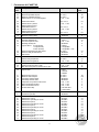
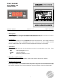
* Parameters ALFANET 95.
Description of Parameter
Range
01
02
03
04
Switching differential
Minimum adjustable set point
Maximum adjustable set point
Readout above -10C in whole degrees
0,1..15,0°C
-50..+50°C
-50..+50°C
0 = No, 1 = Yes
0,5
-50
+50
0
05
06
07
08
09
10
11
Offset control sensor
Defrost sensor-1 present
Readout defrost sensor-1
Offset defrost sensor-1
Defrost sensor-2 present
Readout defrost sensor-2
Offset defrost sensor-2
-15,0..+15,°C
0 = No, 1 = Yes
-15,0..+15,°C
0 = No, 1 = Yes
-15,0..+15,°C
0,0
0
0,0
0
0,0
15
Minimum off time cooling
0...99 Minutes
0
20
21
22
23
24
0 = No, 1 = Yes
0..+50,0°C
0 = No, 1 = Yes
0..90 Minutes
0 = Natural
1 = Hot gas/Elec.
2 = Hot gas/Elec. + Fan
-50..+50°C
0..90 Minutes
0..90 Minutes
0
2,0
0
0
0
25
26
27
Fan switch differential active
Switching differential fan
Fan off if compressor is off
Switching off delay fan
Type of defrost 0=only fan-relay
1=only defr-relay
2=defr.+fan-relay
Switch on temperature fan after defrost
Switch on delay fan after defrost
Drip off time
30
31
32
Maximum defrost time
Defrost-ending temperature
Display fixed during defrost
0..99 Minutes
-50..+50°C
0 = No, 1 = Yes
15
2,0
0
35
36
37
Day/night contact as door contact
Cooling and fan off if door is open
Max. time cooling and fan off when door is open
0 = No, 1 = Yes
0 = No, 1 = Yes
0..99 Minutes
0
0
30
40
Type of alarm
1
41
42
43
44
45
46
47
48
Minimum alarm set point
Maximum alarm set point
Time delay maximum alarm
Time delay minimum alarm
Compressor on by failure control sensor
Alarm off after manual reset
Alarm off after alarm solved
Function alarm relay
0 = None,
1 = Absolute
2 = Relative
-50..+50°C
-50..+50°C
0..99 Minutes
0..99 Minutes
0 = No, 1 = Yes
0 = No, 1 = Yes
0 = No, 1 = Yes
0 = Fail safe alarm,
1 = Control alarm
50
51
Current time (hours)
Current time (minutes)
0..23 Hours
0..59 Minutes
60
61
62
63
64
65
66
67
68
69
70
71
72
Real-time defrost active
Defrost time-1 (hours)
Defrost time-1 (minutes) per 10 min.
Defrost time-2 (hours)
Defrost time-2 (minutes) per 10 min.
Defrost time-3 (hours)
Defrost time-3 (minutes) per 10 min.
Defrost time-4 (hours)
Defrost time-4 (minutes) per 10 min.
Defrost time-5 (hours)
Defrost time-5 (minutes) per 10 min.
Defrost time-6 (hours)
Defrost time-6 (minutes) per 10 min.
0 = No, 1 = Yes
0..23/off Hrs.
0..50/off Min.
0..23/off Hrs.
0..50/off Min.
0..23/off Hrs.
0..50/off Min.
0..23/off Hrs.
0..50/off Min.
0..23/off Hrs.
0..50/off Min.
0..23/off Hrs.
0..50/off Min.
Parameter
4
Standard
value
2,0
0
0
-50
+50
0
0
0
0
0
0
0
off
off
off
off
off
off
off
off
off
off
off
off
Parameter
Description of Parameter
Range
80
Night shift (offset)
-10.0..+10.0
90
95
96
97
98
99
Network number
Software version
Production year
Production week
Series number (x1000)
Series number (units)
1..250
0..255
00..99
1..52
0..255
0..999
Standard
value
0,0
1
-
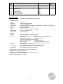
* Technical data.
Type
CONTROL-UNIT:
Range
Read-out
Accuracy
Status LEDs
Operation
Front
Network
Dimensions
Panel cutout
I/O-UNIT:
Supply
Relays
Sensors
Contact input
Dimensions
: ALFANET 95 Cool/Defrosting Thermostat
: -50,0/+50,0C
: 3-digit 7-segments display
: ± 0,5 % of the range.
: ALARM, COMPR., FAN, DEFR.1 and DEFR.2 (On display through C key)
: through pushbuttons on the front.
: Polycarbonate IP65
: RS485-network (2xtwisted-pair shielded)
: 35 x 77 x 71,5mm (hwd)
: 29 x 70mm (hw)
: 230 Vac 50/60Hz (-5/+10%) Max. 3VA
: These two relays have one common;
Ry-1 Alarm
SPDT (NO,NC) 250V/8A (cos =1)
Ry-2 Cool SPST (NO)
250V/8A (cos =1)
These three relays have one common;
Ry-3 Fan SPST (NO)
250V/8A (cos =1)
Ry-4 Defrost-1
SPST (NO) 250V/8A (cos =1)
Ry-4 Defrost-2
SPST (NO) 250V/8A (cos =1)
: 3x SM 811 (PTC 1000/25C).
: 1x Day/Night switch (open = night shift active) or
Door contact (cooling and fan off when door is open)
: 90x71x58mm (hwd) for rail mounting
- Equipped with memory protection in case of power failure.
- Equipped with a self-testing function.
- Equipped with sensor failure detection.
- Connection through screw terminals on supply/relay module.
- Special models available on request.
5
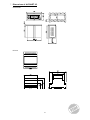
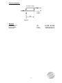
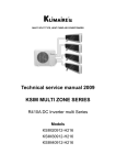
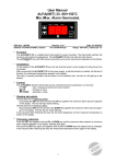
* Dimensions of ALFANET 95.
Control-unit
I/O-unit
6
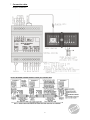
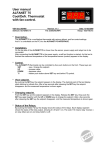
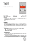
* Connection data.
Diagram: 042527w2
7
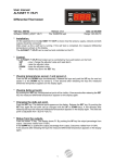
* Function diagram.
* Address
VDH Products BV
Produktieweg 1
9301 ZS Roden
Netherlands
Tel:
Fax:
Email:
Internet:
8
+31 (0)50 - 30 28 900
+31 (0)50 - 30 28 980
[email protected]
www.vdhproducts.nl