1
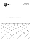
USER MANUAL MONOMAG 180 MIG/MAG WELDING MACHINE www.magmaweld.com CONTENTS SAFETY RULES.................................................................................................................................................2 1. TECHNICAL INFORMATIONS.......................................................................................................................6 1.1 GENERAL EXPLANATIONS....................................................................................................................6 1.2 COMPONENTS OF MONOMAG 180 ......................................................................................................6 1.3 DATA PLATE ............................................................................................................................................7 1.4 TECHNICAL SPECIFICATIONS ..............................................................................................................7 1.5 ACCESSORIES .......................................................................................................................................7 2. INSTALLATION ..............................................................................................................................................8 2.1 UPON RECEIPT AND CLAIMS ...............................................................................................................8 2.2 INSTALLING AND WORKING RECCOMENDATIONS............................................................................8 2.4 WELDING CONNECTIONS ...................................................................................................................9 2.4.1 Connect the Torch .........................................................................................................................9 2.4.2 Connecting the Earth Cable to the Machine and to the Workpiece ..............................................9 2.4.3 Connect the Gas Cylinder .............................................................................................................9 3. OPERATION.................................................................................................................................................10 3.1 CONNECT THE MACHINE TO THE MAINS..........................................................................................10 3.2 CHOOSING THE RIGHT FEED ROLLS ................................................................................................10 3.3 LOADING THE SPOOL AND THREADING THE WIRE.........................................................................10 3.4 ADJUSTING THE GAS FLOW ...............................................................................................................10 4. WELDING ....................................................................................................................................................11 4.1 ADJUSTING THE STICK OUT ...............................................................................................................11 4.2 WELDING PARAMETERS .....................................................................................................................11 5. MAINTENANCE AND TROUBLESHOOTING..............................................................................................12 5.1 PERIODIC MAINTENANCE...................................................................................................................12 5.2 NONPERIODIC MAINTENANCE...........................................................................................................12 5.3 BASIC TROUBLESHOOTING ...............................................................................................................13 5.4 FUSES ...................................................................................................................................................13 APPENDIX 1: SPARE PARTS LIST................................................................................................................14 APPENDIX 2: ELECTRICAL DIAGRAM .........................................................................................................15 Monomag 180 1 SAFETY RULES OBEY ALL THE SAFETY RULES STATED IN THE MANUAL! IDENTIFYING SAFETY INFORMATION These symbols are being used to identify potential risks. When seen a safety symbol in the manual, it must be understood that there is an injury risk and following instructions must be read carefully to avoid potential risks. While welding, keep the third persons and especially the children away from the work area. UNDERSTANDING THE SAFETY WARNINGS Read carefully the manual and the labels and the safety warnings on the machine. Make sure that the warning labels positioned on your machine are in good order. Renew the damaged and the missing labels. Learn to operate the machine and how to make the controls properly. Operate your machine in convenient work areas. Improper modifications affect the safety of your machine negatively and shorten its lifetime. ELECTRICAL SHOCK CAN BE FATAL Installation procedure must comply with national electricity standards and other relevant regulations and ensure that installation is performed by qualified persons. Wear dry insulating gloves free of damage and body protection. Do not touch electrode with bare hand. Do not wear wet or damaged gloves and body protection. Do not touch live electrical parts. Never touch electrode while in contact with working surface, ground or another electrode which is connected to a different machine . Protect yourself from electric shock by insulating yourself from work and ground. Use non-flammable, dry insulating material if possible, or use dry rubber mats, dry wood or plywood, or other dry insulating material big enough to cover your full area of contact with the work or ground, and watch for fire. Never connect more than one electrode to the electrode holder. Turn off the machine, when not in use . Disconnect input plug or swtich off the power before working on the machine. Frequently inspect input power cord for damage or bare wiring - repair or replace cord immediately if damaged. Be sure that the machine is properly grounded. HOT PARTS CAN CAUSE SEVERE BURNS Do not touch hot parts. Allow cooling time before servicing. If needed to hold hot parts, use appropriate tool, insulating gloves and fireproof clothes. 2 Monomag 180 SAFETY RULES BREATHING WELDING FUMES CAN BE HAZARDOUS TO YOUR HEALTH Inhaling fumes and gases over a long period of time, generated during welding is dangerous and forbidden . Irritation of the eyes, nose and throat are symptoms of inadequate ventilation. Take immediate steps to improve ventilation. Do not continue welding if symptoms persist. Install a natural or forced air ventilation system in the work area. Install an adequate ventilation system in the welding and cutting area, if needed install a system that can remove the fume and vapor accumulated in the entire work area, to prevent pollution use adequate filtration in discharge. In the event of welding in small, confined places, or welding lead, beryllium, cadmium, zinc, zinc coated or painted materials; also wear a fresh air supplied respirator in addition to the above mentioned rules . Always have a trained watchperson nearby, while working in small confined places. Avoid working in such confined places if possible. If gas cylinders are grouped in a different area, make sure that it is a well-ventilated area. When not being used, turn off the main cylinder valve and watch out for gas leakage . Shielding gasses such as argon is denser than air and when being used in confined places, it can be inhaled which is dangerous for health. Do not perform welding operations near chlorinated hydrocarbon vapors produced by degreasing or painting. ARC RAYS CAN BURN EYES AND SKIN Use adequate welding helmet with correct shade of filter (4 or 13 considering EN 379) to protect your eyes and face. Protect open parts of your body (arms, neck and ears) from arc rays by adequate protective clothing. To protect others by arc rays and hot metals, surround the working area with flame proof curtains which are higher than eye level and put up warning boards. SPARKS & FLYING METALS CAN INJURE EYES Welding, wire brushing and grinding cause sparks and flying metal. To prevent injuries wear appropriate safety glasses with side shields even under your welding helmet . MOVING PARTS CAN CAUSE INJURY Keep away from moving parts. Keep all doors, panels, and guards closed and secured. Wear shoes with metal protection over the fingers. Monomag 180 3 SAFETY RULES NOISE CAN DAMAGE HEARING Noise from certain industrial processes or equipments can damage hearing. Wear approved ear protection if noise level is high. WORKING IN SMALL AND CONFINED PLACES CAN BE DANGEROUS While welding and cutting in small, confined places, always have a trained watchperson nearby. Avoid working in such confined places. WELDING WIRE MAY CAUSE INJURY Do not point the torch toward any part of a human body, other persons or any type of metal when unwinding welding wire. While extracting the wire from the spool by hand, it may spring suddenly and injure you or a nearby person, protect especially your eyes and face. WELDING CAN CAUSE FIRE OR EXPLOSION Never weld near flammable material. It may cause fire or explosions. Before starting to weld, move flammables away or protect them with flame-proof covers. Do not weld on and cut closed tubes or pipes. Before welding on closed containers, open and clear them entirely. Welding operations on these parts must be performed with the utmost caution. Never weld containers or pipes containing or which have contained substances that could give rise to explosions. Welding equipments warms up so never position them on flammable surfaces. Welding sparks can cause fire. For that reason, keep extinguishing means, such as fire extinguishers, water and sand which are easy to reach. Keep security valves, regulators and other valves, used on flammable, explosive and compressed gas circuits, in good condition. MAINTENANCE MADE BY UNQUALIFIED PERSONS MAY CAUSE INJURIES Electrical devices should not be repaired by unqualified persons. Improper repairs can cause serious injuries or even death during applications. The components of the gas circuit works under pressure. The service given by unqualified persons may cause explosions and operators can be injured seriously. 4 Monomag 180 SAFETY RULES FALLING UNIT CAN CAUSE INJURY Wrong positioned power source or other equipment may cause serious injury to persons or damage to objects. While repositioning the power source always carry by using the lifting eye. Never pull cable, hose or torch. Always carry the gas cylinders separately. Before carrying the welding and cutting equipment, disassemble all the connections between and separately carry the small ones by handgrips and the big ones by lifting eyes or by using appropriate vehicles like forklifts. Install your machine on flat platforms having maximum 10° slope that it does not fall over. Install it on well ventilated, non-confined places away from the dust, also avoiding the risk of falling caused by cables and hoses. For gas cylinders not to fall over, attach it to the mobile machine or to the wall with a chain. Ensure that operators easily reach the controls and connections on the machine. OVERUSE CAN CAUSE OVERHEATING Allow cooling period; follow rated duty cycle. Reduce current or reduce duty cycle before starting to weld again. Do not block airflow through the unit. Do not filter airflow to unit without the approval of manufacturer. ARC WELDING CAN CAUSE INTERFERENCE Electromagnetic energy arising during welding and cutting operations can interfere with sensitive electronic equipment such as microprocessors, computers, and computer-driven equipment such as robots. Be sure all equipment in the welding area is electromagnetically compatible. To reduce possible interference, keep weld cables as short as possible, close together, and down low, such as on the floor. To avoid possible EMC damages, locate welding operation as far as possible (100 meters) from any sensitive electronic equipment. Be sure this welding machine is installed and grounded according to this manual. If interference still occurs, the user must take extra measures such as moving the welding machine, using shielded cables, using line filters, or shielding the work area . PROTECTION Do not expose the welding machine to rain, protect from water drops and vapour. ENERGY EFFICIENCY Choose appropriate welding method and welding machine for your work. Choose appropriate welding current and welding voltage for the material and its thickness. If you will have a long break after welding, turn off the machine after cooler fan cooled the machine. Monomag 180 5 TECHNICAL INFORMATION 1. TECHNICAL INFORMATION 1.1 GENERAL EXPLANATIONS Monomag 180 is a single phase, step controlled, constant voltage, compact MIG/MAG welding equipment to be used especially for intensive thin metal repair applications. Any kind of metal can be welded with this machine, if proper welding wire and gas is used. For mild steel welding, even under CO2 you can weld with low spatter and stable arc. The concept of this machine is based on our industrial 3 phase machines, only the wire feeder is 2 wheel drive. The machine is fan cooled and thermally protected against overheating. 1.2 COMPONENTS OF MONOMAG 180 13 12 CO2 Ø : 0,6 mm mm A V Ø : 0,8 mm mm 4 5 8 1 2 3 3 4 5 Ar/CO2 (80/20) 2 3 2 3 5 5 7 13,5 0,5 1 1 4 45 55 70 115 2 3 4 5 FUSE 6 7 1 1 8 16 17 20 22 1 2 3 4 3 5 5 6 8,5 11 4 5,5 7 4,5 6 75 90 105 80 100 125 145 19 20 21 18 19 21 22 FUSE FUSE 18 F1 EN 60974-1 EN 60974-10 F2 MONOMAG 180 1R Seri No : 30 A / 16 V - 140 A / 21 V 60 % X 20 % F3 U1 1R 5 2 3 5 220 4 5 6 4 5 7 50 Hz 3,5 5,5 7 4,5 5,5 9,5 120 135 160 20 21 25 20 20 21 CL.I. 2 H I1 T 32 A S1 100 % 80 A 140 A 21 V U2 V 3 100 125 140 I2 U0 V 14 - 29 2 18 20 Ø : 1,0 mm 3 3 35 60 70 A V A V 2 2 19 20 21 mm 5 0,5 1 60 A 18 V A I1 17 V A 28 13 6,2 kVA 2,9 kVA IP 21 I1 A 9,7 2,1 kVA S 6 10 m/min Th 3 7 11 DİKKAT BU PRİZ CO2 ISITICISI İÇİNDİR. KESİNLİKLE BAŞKA MAKSATLA KULLANMAYINIZ 16 MONOMAG 180 9 4 aaaaaaaaaaaaaaaaaaaaaaaaaaaaa aaaaaaaaaaaaaaaaaaaaaaaaaaaaa aaaaaaaaaaaaaaaaaaaaaaaaaaaaa aaaaaaaaaaaaaaaaaaaaaaaaaaaaa aaaaaaaaaaaaaaaaaaaaaaaaaaaaa aaaaaaaaaaaaaaaaaaaaaaaaaaaaa aaaaaaaaaaaaaaaaaaaaaaaaaaaaa aaaaaaaaaaaaaaaaaaaaaaaaaaaaa aaaaaaaaaaaaaaaaaaaaaaaaaaaaa aaaaaaaaaaaaaaaaaaaaaaaaaaaaa aaaaaaaaaaaaaaaaaaaaaaaaaaaaa aaaaaaaaaaaaaaaaaaaaaaaaaaaaa aaaaaaaaaaaaaaaaaaaaaaaaaaaaa aaaaaaaaaaaaaaaaaaaaaaaaaaaaa aaaaaaaaaaaaaaaaaaaaaaaaaaaaa aaaaaaaaaaaaaaaaaaaaaaaaaaaaa aaaaaaaaaaaaaaaaaaaaaaaaaaaaa aaaaaaaaaaaaaaaaaaaaaaaaaaaaa aaaaaaaaaaaaaaaaaaaaaaaaaaaaaaaaaaaaaaaaaaa aaaaaaaaaaaaaaaaaaaaaaaaaaaaa aaaaaaaaaaaaaaaaaaaaaaaaaaaaa aaaaaaaaaaaaaaaaaaaaaaaaaaaaa aaaaaaaaaaaaaaaaaaaaaaaaaaaaa aaaaaaaaaaaaaaaaaaaaaaaaaaaaa aaaaaaaaaaaaaaaaaaaaaaaaaaaaa aaaaaaaaaaaaaaaaaaaaaaaaaaaaa aaaaaaaaaaaaaaaaaaaaaaaaaaaaa aaaaaaaaaaaaaaaaaaaaaaaaaaaaa aaaaaaaaaaaaaaaaaaaaaaaaaaaaa aaaaaaaaaaaaaaaaaaaaaaaaaaaaa aaaaaaaaaaaaaaaaaaaaaaaaaaaaa aaaaaaaaaaaaaaaaaaaaaaaaaaaaa aaaaaaaaaaaaaaaaaaaaaaaaaaaaa aaaaaaaaaaaaaaaaaaaaaaaaaaaaa aaaaaaaaaaaaaaaaaaaaaaaaaaaaa aaaaaaaaaaaaaaaaaaaaaaaaaaaaa aaaaaaaaaaaaaaaaaaaaaaaaaaaaa aaaaaaaaaaaaaaaaaaaaaaaaaaaaa aaaaaaaaaaaaaaaaaaaaaaaaaaaaa aaaaaaaaaaaaaaaaaaaaaaaaaaaaa aaaaaaaaaaaaaaaaaaaaaaaaaaaaa aaaaaaaaaaaaaaaaaaaaaaaaaaaaa a a a a a a a a a a a a a a a 16 15 14 Figure 1: Front View 1 2 3 4 5 6 7 8 9 6 ON/OFF and Voltage Step Switch Wire Feeding Speed Adjustment Knob Torch Connector Earth Clamp Socket Welding Parameters Chart Gas Supply Inlet CO2 Heater Socket (220 VAC) Fuses Mains Cable Figure 2: Back View 10 11 12 13 14 15 16 17 18 Thermic Lamp Mains Lamp Lifting Eye Handle Swivel Wheel Braked Swivel Wheel Wheel Drum Feeding Gas Cylinder Safety Chain Monomag 180 TECHNICAL INFORMATION 1.3 DATA PLATE MAGMA MEKATRONİK MAKİNE SAN. VE TİC. A.Ş. 1R EN 60974-1 EN 60974-10 Organize Sanayi Bölgesi 5.Kısım Manisa - TÜRKİYE Single Phase Transformer Rectifier MONOMAG 180 Horizontal Characteristics 1R Seri No : MIG / MAG Welding 30 A / 16 V - 140 A / 21 V 60 % X 20 % I2 U0 V 14 - 29 U1 1R U2 I1 V 220 CL.I. H 140 A 21 V A S1 18 V 17 V A 28 13 6,2 kVA 2,9 kVA T 32 A 50 Hz 60 A I1 I1 3R Appropriate To Operate In Dangerous Work Area S Direct Current A 9,7 2,1 kVA S IP 21 Line Input 3 Phase Alternative Current 100 % 80 A Fuse X U0 U1 U2 :Duty Cycle* :Open Circuit Voltage :Line Voltage and Frequency :Rated Welding Voltage I1 :Input Current I2 :Rated Welding Current IP 21:Protection Class S1 :Input Power CL.I. :Insulation Class *Duty Cycle Temperature (°C) 1 6 min. 2 4 min. 6 min. 4 min. 6 min. 4 min. Time (min.) Duty cycle defines the percentage of welding time out of a period of 10 minutes at a given current and ambient temperature (standard is 40°C). For example, a welder with 60% duty cycle must be rested (2) for 4 minutes, after 6 minutes of continuous welding (1). 1.4 TECHNICAL SPECIFICATIONS TECHNICAL SPECIFICATIONS UNIT Line Voltage (1 Phase) Input Power (20%) VALUE 220 V / 50 Hz kVA 6.2 Recommended Line Fuse A 32 Input Current (20%) A 28 ADC 30 - 140 Welding Current Range Voltage Adjustment Steps (Coarse x Fine) 7 Rated Welding Current (20%) ADC 140 Dimensions (LxWxH) mm 888x455x870 kg 79 mm 0.6 - 0.8 m/min 1 - 17 Weight Drive Roll Size (V socket) Wire Feding Speed Protection Class IP21 1.5 ACCESORRIES STANDARD ACCESORRIES PIECE Torch 1 Electrode Holder and Cable 1 Gas Hose (2m) 1 Monomag 180 7 INSTALLATION 2. INSTALLATION 2.1 TESLİM UPON RECEIPT AND CLAIMS ALIRKEN DİKKAT EDİLECEK HUSUSLAR Be sure that you have received all the items that you have ordered. In case of any item is missing or damaged, contact your supplier immediately. In the event of damaged or missing delivery, draw up a record, take a photo of the damage and report it to the shipping agency and MAGMA MEKATRONIK with the photocopy of shipping bill. Standard pallet contains: ú Power Source ú Earth Cable ú Gas Hose ú User Manual E-mail: [email protected] Fax: +90 236 226 27 28 2.2 INSTALLATION AND WORKING RECOMMENDATIONS • Use lifting eyes or fork-lift to carry the machine. DO NOT lift the machine together with the gas cylinder. Transport and place the device on a firm and level ground so that it may not fall over. The maximum permissible angle of inclination for transport and assembly is 10°. • For a better performance, keep the machine at least 30 cm away from the surrounding objects. Beware of excessive heat, dust and humidity around the machine. Try not to operate the machine under direct sunlight. Machines should be operated on lower capacities when ambient air temperature exceeds 40ºC. • Avoid welding at outdoors where it is windy and rainy, if this is a must, protect the welding area with curtains, mobile screens or tents. • Ensure that operators can easily reach the machine controls and connections. • Use suitable welding fume extraction systems. Use breathing apparatus if there is a risk of inhaling in confined places. 8 Respect the duty cycles given at the data plate. Exceeding the duty cycles frequently can damage the machine and this would void the warranty. • Do not use stronger fuses than those stated on the data plate. • Ensure that the earth clamp is tightly connected as close as possible to the welding location. Do not let welding current flow through any media other than welding cables; e.g. over the machine itself, gas tubes, chains, ball bearings, etc. When the gas cylinder is placed on the machine, immediately lock the chain to secure the cylinder, if it is the stand alone then the cylinders should be secured to a wall by a chain. • The electrical socket behind the machine is for CO2 heater only, it is not recommended to connect other devices. Monomag 180 INSTALLATION 2.4 WELDING CONNECTIONS 2.4.1 Connecting the Earth Cable to the Workpiece To increase the quality of welding, earth clamp should be clamped tightly as close as possible to the welding area. 2.4.2 Connecting the Gas Cylinder 21 25 24 19 20 18 22 23 Figure 3: Connecting The Gas Cylinder 18 Gas Cylinder Safety Chain 19 Gas Pressure Regulator 20 Gas Cylinder 21 Gas Cylinder Valve 22 Pressure Adjustment Valve 23 Gas Hose 24 Flowmeter 25 Manometer 26 CO2 Heater After placing the gas cylinder on its platform, fasten it with the chain. To operate safely and get best results use approved gas regulators and heaters. Open the gas cylinder valve (20) few times in order to blow out any dirt or particles. If CO2 is going to be used, first connect the CO2 heater (26) and then connect the gas pressure regulator (19) to the gas cylinder (20). Connect one end of gas hose (23) to the gas supply inlet (6) at the back panel of the machine and connect the other end to the gas pressure regulator (19). 6 Figure 4: Connecting Gas Hose to the Machine Set the gas flow rate with the pressure adjustment valve (22). For more information about gas adjustment check the following page. Monomag 180 9 OPERATION 3. OPERATION 3.1 CONNECTING TO THE MAINS Before plugging your machine to the electrical line, check if the correct voltage exists. SWITCH ON the machine via power switch (1) and check if mains lamp (11) lights up and cooler fan works. While inserting the plug into the socket, pay attention that main switch is positioned to “OFF” “0”. 3.2 CHOOSING THE RIGHT FEEDING ROLLS For steel and stainless steel wires use V-shape rolls, for flux cored wires use knurled V-shape rolls, for aluminium wires use U-shape rolls. If you need to change the wire feeding roll, remove the screw (30) of the feeding roll. Unlock the pressure assembly (28) by pulling down the spring knob (29). 29 Remove the existing rolls and put in the rolls which you will use. Both sides of the rolls are labeled according to appropriate wire diameter. Rolls must be inserted into the flange in such a way that appropriate diameter of the wire to be feeded is seen from outside. After installing the rolls, the screw (30) should be postioned and fastened. 0,8 28 1,0 1,0 1,0 0,8 0,8 30 Figure 6: Wire Feeding Roll Figure 5: Wire Feeding Motor 3.3 MOUNTING THE SPOOL AND THREADING THE WIRE 33 3 2 32 1 Figure 8: Threading the Wire Unlock the pressure assembly (28) by pulling down the spring knob (29) (Figure 8). 31 Figure 7: Placing the Wire Spool Remove the spool support nut (31). Place the MIG/MAG wire spool (32) and screw the spool support nut (29) tightly. Take the wire from the wire spool by paying attention not to release it and thread the wire through the wire feeding rolls into the torch liner, then pull down the pressure assembly (28) and lock the spring knob (29). 3.4 ADJUSTING THE GAS FLOW For accurate gas flow rate adjustments, use the following table. Practical adjustment of the gas flow rate (CO2, Ar, MIX) is 10 times of the diameter of the wire. EXAMPLE: Diameter of the wire: 1,2 mm Gas flow rate: 10 x 1,2 = 12 lt/min 10 Diameter DO NOT ADJUST THE GAS FLOW DURING WIRE FEEDING. Mild Steel and Metal Flux Cored Stainless Steel 8 lt/min 8 lt/min Aluminium Flux Cored 8 lt/min 7 lt/min 9 lt/min 9 lt/min 9 lt/min 8 lt/min 10 lt/min 10 lt/min 10 lt/min 9 lt/min 12 lt/min 12 lt/min 12 lt/min 11 lt/min RS 200 MK / RS 300 MK / RS 400 MK WELDING 4. WELDING 4.1 ADJUSTING THE STICK OUT Contact Tip In order to obtain good welding characteristics, stick out has to be adjusted according to the table, which is a function of the diameter of the wire. Nozzle Short Arc d Globular Transfer 15d 5-8 mm 8-12d d 2-5 mm 10d 0-3 mm d Spray Arc Figure 15: Arc Lengths Arc Type Wire Diameter (d) Coefficient Free Wire Length Short Arc 1,0 10d 10 Globular Transfer Spray Arc 1,0 12d 12 1,0 15d 15 4.2 SELECTING THE WELDING PARAMETERS CO2 Ø : 0,6 mm mm A V Ø : 0,8 mm mm Ø : 1,0 mm mm Monomag 180 0.5 1 2 0.5 1 2 3 2 3 4 1 2 3 5 3 5 8 4 5 7 13.5 35 60 70 45 55 70 115 19 20 21 16 17 20 22 1 2 3 1 2 3 5 3 4 5 3 4 5 6 6 8.5 11 4 5.5 A V 7 4.5 80 100 125 145 75 90 105 19 20 21 18 19 21 2 3 5 2 3 5 4 5 6 4 5 7 3.5 5.5 A V Ar/CO2 (80/20) 22 7 4.5 5.5 9.5 100 125 140 120 135 160 20 21 25 20 20 21 11 MAINTENANCE AND TROUBLESHOOTING 5. MAINTENANCE AND TROUBLESHOOTING Strictly follow the instructions contained in safety rules while servicing the machine. Before removing any screw on the machine for maintenance, it should be disconnected from the mains and 10 seconds should be allowed for capacitor discharging. 5.1 PERIODIC MAINTENANCE Once every three months Clean the labels on the machine. Repair or replace the worn out labels. Clean and tighten weld terminals. Repair or replace the worn out welding cables. Check the isolation of the torch, electrod holder, earth clamp and their cables. Once every six months Open the covers of the machine and clean with dry air. OR NOTE: The above recommended maintenence periods are indicative according to our general experience, these may vary from work shop to work shop and the conditions of the welding site. DO NOT CONNECT THE MAINS ELECTRIC BEFORE CLOSING THE CABINET PANELS. 5.2 NONPERIODIC MAINTENANCE Wire feeding rolls and the surrounding parts should be kept clean and the surface of the drive rolls should definitely not be lubricated. Each time the wire is replaced, the dirt accumulated on the mechanism should be cleaned by a brush or dry air . Contact tip and nozzle on the torch have to be cleaned regularly and changed if required. Contact tips must be in good condition, longer tips generally give better results. 12 Monomag 180 MAINTENANCE AND TROUBLESHOOTING 5.3 BASIC TROUBLESHOOTING REMEDY TROUBLE REASON Machine does not work. Electronic Card is out of order. Fuse is blown out “F3”. Contact your authorized technical service. Change the fuse. Electronic Card is out of order. Contact your authorized technical service. The drive roll is not appropriate for the wire diameter. Select the appropriate drive roll. Pressure in the pressure roll is not enough. Adjust the pressure roll. Contact tip size is wrong or it is worn out. Change the contact tip. Pressure in the pressure roll is not enough. Adjust the pressure roll. Co2 heater fuse is blown out “F3”. Change the fuse. Protective gas pressure is not appropriate. Check the gas and its adjustment. Contact the authorized service if the gas adjustment can not be made. Fuse is blown out “F1”. Change the fuse. Wire feeder doesn’t work. Wire feeder works but wire is not fed. Trouble in welding operation. Ventilator does not function. Machine works noisily. Ventilator motor is out of order. Contact your authorized technical service. Ventilator motor is out of order. Contact your authorized technical service. Welding current isn’t stabilized Some diodes in the power pack and/or cannot be adjusted. are out of order. Contact your authorized technical service. Heater socket is not working. Change the fuse. Fuse is blown out “F2”. 5.4 FUSES Fuse Amper Property The Circuit Protected F1 0.8A T Fan F2 1A F CO2 Heater Socket F3 10A F Wire Feeder Monomag 180 13 APPENDIX 1 SPARE PARTS LIST 14 NO MATERIAL CODE 1 A253200003 DESIGNATION Gas Ventile 2 A300101005 Glass Fuse - Fast 1A 3 A300101015 Glass Fuse - Fast 10A 4 A300102003 Glass Fuse - Delayed 800mA 5 A300190001 Glass Fuse Socket 6 A310310002 Signal Lamp Neon 240VAC 7 A310310004 Signal Lamp Neon 24VAC 8 A377100004 Mono-phase Machine Socket - 16A/240V 9 A410200003 Stone Resistor - 11W 220 Ohm 10 A410801001 Carbon Potentiometer - 0,5W 11 A229500002 Wire Feeding Speed Adjustmend Knob 12 A430800000 LED 13 A490300004 Plastic Card Holder 14 A430901002 Diode Bridge 15 A314800102 Temperature Limiting Switch 16 K304400012 Control Transformer 17 A229900004 Wire Spool Support 18 A308010004 Changeover Switch 19 A250100003 Axial Aspirator 20 A430902004 Diode Bridge 21 K405000064 Electronic Board 22 A377900106 Welding Socket 23 K309002202 Wire Feeding System 24 K304500028 Choke Coil 25 K304000048 Main Transformer 26 K302200032 Primary Secondary Coil 27 A225220008 Swivel Plastic Wheel 28 A225222010 Plastic Wheel 29 A229102002 Bakelite U Arm 30 A229300006 Panel Cabinet Lock 31 A229200004 Hinge Monomag 180 APPENDIX 2 ELECTRICAL DIAGRAM 3 1 1 1 4 2 Pk1 4 4 4 4 4 1 2 3 4 5 6 7 4 6 12 3 10 16 2 5 18 1 14 8 TR1 BR2 BR1 22000uF/63V 1k R N E 6 7 ~ + 220R/11W R1 220R/11W R2 JC JB 24VDC/90W 1 + 4 3 2 1 4 4 - RE 414 5mm red led 0 TR2 24VAC KBL08 TH F-10A 220VAC ~ JA 2 22000uF/63V TRIGGER F3 F-1A 220VAC C1 T-0.8A F1 L1 860mH RELAY M1 2 1 + - 275VAC VR1 V1 220VAC 15 Monomag 180 + - C2 1 2 3 4 5 6 7 8 9 10 F2 GREEN NEON WIRE SPEED THERMIC M2 NOTES FACTORY Organize Sanayi Bölgesi 5.Kısım 5503. Sokak No:1 MANİSA +90 236 226 27 00 +90 236 226 27 28 OWM 02.02.2011 Made in TÜRKİYE www.magmaweld.com