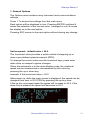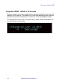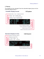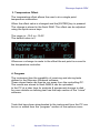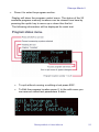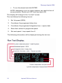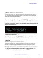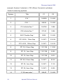
1
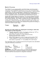
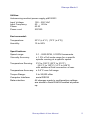
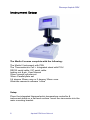
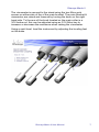
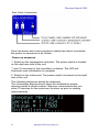
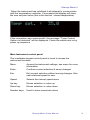
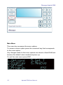
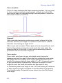
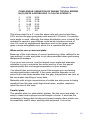
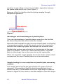
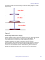
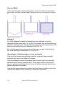
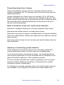
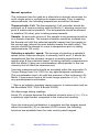
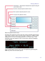
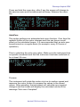
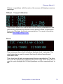
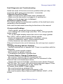
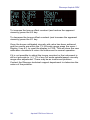
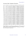
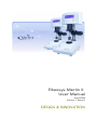
Rheosys Merlin II
User Manual
Aug 2008
Volume 1, Issue 2
DESIGN & INNOVATION
Rheosys Merlin II
Table of Contents
Merlin II Overview......................................................................... 4
Instrument Setup
...................................................................................................... 6
Main Instrument control panel
9
Main Menu
10
Manual operation
26
Supervisor / Service settings:
29
Rheosys Merlin II User Manual
3
Rheosys Asphalt DRV
Merlin II Overview.
The Merlin II is a programmable controlled shear rate rheometer /
viscometer with integrated temperature control and automated test
capabilities. The Merlin II measures fluid parameters of Shear Stress
and Viscosity at given Shear Rates. Viscosity is a measure of a
fluid’s resistance to flow. The principle of operation of the Merlin II is
to drive a spindle (which is immersed in the test fluid) at the set
speed with a high degree of accuracy. The viscous drag of the fluid
against the spindle is measured by the current required to maintain
the rotational speed. The current is measured with a high resolution
current sensing transducer. The measuring range of the Merlin II (in
centipoise) is determined by the rotational speed of the spindle, the
size and shape of the spindle, the container the spindle is rotating in,
and the full scale torque range.
Torque
Dyne•cm
200,000.0
mN•m
20.0
All units of measurement are displayed according to either the
CGS system or the SI system.
1. Viscosity appears in units of centipoise (shown as “cP”) or
milliPascal-seconds (shown as mPa•s).
2. Shear Stress appears in units of Pascal’s (Pa.).
Newtons/square meter (“N/m2”).
3. Shear Rate appears in units of reciprocal seconds (“1/s”).
4. Torque appears in units of micro Newton-meters(“uNm”),
also shown as percent “%” of available full scale torque.
The equivalent units of measurement in the SI system are calculated
using the following conversions:
SI
CGS
Viscosity:
1 mPa•s
=
1 cP
Shear Stress: 1 Newton/m2 =
10 dyne/cm2
Torque:
1 N•m
=
107 dyne•cm
WARNING: Use of this instrument in a manner not specified by
Rheosys may result in incorrect readings or instrument failure.
Please read this manual prior to using the instrument.
4
Asphalt DRV User Manual
Rheosys Merlin II
Utilities:
Autosensing medical power supply pt#100201
Input Voltage:
Input Frequency:
Power:
Power cord
100 – 250 VAC
50 - 60 Hz
60 W
IEC320
Environmental:
Temperature:
23°C (± 4°C) (73°F (± 6°F))
Humidity:
10 to 80%
Specifications:
Speed range:
0.1 - 2000 RPM, 0.1RPM Increments.
Viscosity Accuracy:
± 1.0% of full scale range for a specific
spindle running at a specific speed.
Temperature Sensing:
0°C to 100°C (32°F to 212°F)
-10.0°C to 120°C (14°F to 248°F)
with additional fluid connection at rear.
Temperature Accuracy: ± 0.5°C over full range
Torque Range:
0 to 20,000 uNm
Computer Interface:
serial RS232
Data retention:
All changes made to configuration settings
are stored to flash RAM & recalled at power
up.
Rheosys Merlin II User Manual
5
Rheosys Asphalt DRV
Instrument Setup
The Merlin II comes complete with the following:
The Merlin II Instrument with PSU
The Thermoelectric Cell + Integrated stand with PSU
RS232 serial cable, I2C serial cable
locking nut & pin, User Manual
25mm coaxial cylinder set
30mm Parallel plate set
5.4 degree 30mm cone or 2 degree 30mm cone
Windows research software “micra”
Setup.
Place the integrated thermoelectric temperature controller &
instrument stand on a flat level surface. Insert the viscometer into the
main mounting bracket.
6
Asphalt DRV User Manual
Rheosys Merlin II
The viscometer is secured to the stand using the two Allen grub
screws on either side of the of the main bracket. The main bracket &
viscometer are raised and lowered by turning the knob on the right
hand side. To the rear of the knob located on the main collar is a
3/16 brake nut, this can be adjusted using an 3/16 Allen key to
increase or decrease the resistance when raising the viscometer.
Using a spirit level, level the instrument by adjusting the leveling feet
on the base.
Rheosys Merlin II User Manual
7
Rheosys Asphalt DRV
Once the power and communications cables have been connected,
the power on sequence is as follows:
Power up sequence
1. Switch on the temperature controller. The power switch is located
on the right rear side of the unit.
** wait 10 seconds for the controller to initialize. The LED will
illuminate once initialization is complete.
2. Switch on the instrument. The power switch is located on the right
rear of the unit.
The following sequence should be observed:
The Viscometer display should show the initialization screen
showing model & serial number. Rheosys recommends that you
allow 10 minutes for the instrument to warm up prior to making
measurements.
8
Asphalt DRV User Manual
Rheosys Merlin II
When the instrument has initialized it will attempt to communicate
with the temperature controller. If successful the display will show
the new set point value (this is the last set / stored temperature).
If the connection was unsuccessful, the message "Temp Control
Option not detected" will be displayed. Check the cables and re-try
power up sequence.
Main Instrument control panel
The membrane keypad control panel is used to access the
instrument functions.
Menu.
Access the instrument settings, see menu for more
information
Enter.
Confirms current selection & saves changes
Esc.
Exit current selection without saving changes. Also
sets rotational speed to zero.
Speed.
Selects the manual speed menu
Up key.
Moves selection or value up
Down key.
Moves selection or value down
Number keys.
Used to enter numerical values
Rheosys Merlin II User Manual
9
Rheosys Asphalt DRV
Main Menu
The menu key accesses the menu options.
To access a menu option press the numerical key that corresponds
to the menu option.
Any changes made to the menu options are stored in flash RAM and
become the default value recalled at power up.
To exit the main menu press ESC.
10
Asphalt DRV User Manual
Rheosys Merlin II
1. General Options
The Options area contains many instrument and communications
settings.
Press 1 To access the settings from the main menu.
Each option will be displayed in turn. Pressing ENTER confirms &
stores the selection of the current value (changed or not) & moves
the display on to the next option
Pressing ESC moves to the next option without storing any change.
Set Increment: default value = 20.0
The Increment value provides a quick method of stepping up or
down a pre-defined speed increment (RPM)
To change the current value use the numerical keys, press enter
when done or escape to ignore changes
When the instrument is in the main display mode, the rotational
speed can be incremented or decremented by this value by
pressing the up or down key.
example: if the increment value = 20.0
After power up, while the main screen is displayed, the speed can be
changed from zero to 20.0 PRM by pressing the up key once.
If the up key is pressed again the speed will increase to 40.0, if the
down key is pressed the speed will decrease to 20.0.
Rheosys Merlin II User Manual
11
Rheosys Asphalt DRV
Integration Width: default = 10 seconds
The raw torque can be averaged over several cycles to improve the
stability of the signal. The trade off is that the sampling time at each
speed has to be increased to a minimum of the integration width.
To change the value use the up/dn keys, press enter when done or
escape to ignore changes
12
Asphalt DRV User Manual
Rheosys Merlin II
2. Display
The display can be changed from the standard display layout to the
scientific display layout.
Rheosys Merlin II User Manual
13
Rheosys Asphalt DRV
3. Temperature Offset
The temperature offset allows the user to do a single point
temperature calibration.
When the offset value is changed and the [ENTER] key is pressed.
The change is stored in the flash RAM. The offset can be adjusted
using the up/dn arrow keys.
The range is –10.0 to +10.0C
The default value is 0
Whenever a change is made to the offset the set point is re-sent to
the temperature controller.
4. Program
The instrument has the capability of receiving and storing tests
defined in the Rheosys Windows software.
These stored tests can then be run away from the controlling PC.
The results are stored to flash RAM & can be uploaded
to the PC at a later time for analysis & permanent storage to disk.
for more details on defining test see the help section of the "micra"
software.
Tests that have been downloaded to the instrument from the PC can
be run or edited from the "program" section of the options menu.
14
Asphalt DRV User Manual
Rheosys Merlin II
•
Press 4 to enter the program section.
Display will show the program control menu. The status of the 20
available program memory locations can be viewed from here by
pressing the up/dn key to move up or down thru the list.
The following information will be displayed for each test:
•
To quit without running or editing a test press ESC.
•
To Edit the program location press 0. In the edit menu you
can remove stored test parameters & data.
Rheosys Merlin II User Manual
15
Rheosys Asphalt DRV
•
To run the stored test click ENTER.
NOTE: attempting to run an empty location can result in loss of
communication. Switch unit OFF and then back ON.
The display will change to the "run test" screen.
The test follows the following format:
1. Set 1st speed (RPM)
2. Countdown the programed delay time
3. Countdown the programed Integration time + aquire data
4. Store final values for programed speed.
5. Set next speed - loop repeat from 2.
The following information will be displayed during the test run:
16
Asphalt DRV User Manual
Rheosys Merlin II
5. Set T ( Set a new Temperature ).
This option allows the user to change the temperature set point of
the connected temperature controller. The value can be changed
using the UP/DOWN arrow keys.
Once the value has been changed the [ENTER] key will save the set
point and send the change to the temperature controller.
The [ESC] key can be used to quit the menu option without saving or
setting the temperature.
The set point resolution is 1°C
When the user presses the [ENTER] key the set point is stored in
flash ram then sent to the temperature controller.
6. MeaSys
The Measuring System selection option.
Users can change the selected measuring system to match the
spindle or measuring system attached to the instrument. Each
available system has its own display showing the title and constants
C1 & C2.
To view the available systems press the up or down arrows. To
select the currently displayed system press ENTER
Rheosys Merlin II User Manual
17
Rheosys Asphalt DRV
example: System 2 selected = C25 (25mm Concentric cylinders)
Default measuring systems.
System
Title
C1
C2
1
C14 *
140609
10.452
2
C25 *
24694
10.452
3
C14 Infinite Sea **
154700
1.996
4
C25 Infinite Sea **
27160
1.996
5
24/27 Double Gap *
9535
10.452
6
CP 2.5/30, 70um Gap
141471
22.918
7
CP 5.4/30, 150um Gap
141471
10.610
8
PP 15, 0.5mm Gap
1131768
11.250
9
PP 15, 1mm Gap
1131768
5.625
10
PP 15, 2mm Gap
1131768
2.812
11
PP 30, 0.5mm Gap
141471
22.50
12
PP 30, 1mm Gap
141471
11.25
13
PP 30, 2mm Gap
141471
5.625
14
C 25 vane rotor *
24640
10.452
18
Asphalt DRV User Manual
Rheosys Merlin II
15
S21 16.75mm Spindle ***
64400
8.887
16
S27 11.75mm Spindle ***
117100
3.231
Setting the correct gap.
The Merlin II has an adjustable micro collar attached to the stand
column at the rear of the temperature controller. This can be raised
and lowered to set the correct gap for the measuring system in use.
Gap notes:
*
The correct gap for this system is set when the parallel plate
system is inserted and the gap is zero. The desired measuring
system can then be inserted.
**
No set gap. Bob should be fully immersed in sample
*** System not used on Merlin type instrument
Measuring Systems
Measuring systems fall into three basic categories. These are ;
(1) Cone and Plate
(2) Parallel Plates
(3) Cup and bob
Each type has its associated advantages and disadvantages which
will be described in the following sections.
Rheosys Merlin II User Manual
19
Rheosys Asphalt DRV
Cone and plate
This is in many instances the ideal measuring system. It is very easy
to clean, requires relatively small sample volumes and with a little
care can be used on materials having a viscosity down to about ten
times that of water (10 mPa.S).
Figure-6
Cone and plate measuring systems are usually referred to by the
diameter and the cone angle. For instance a CP5.4/30 is a 30mm
diameter cone having an angle of 5.4°
Often cones are truncated. These types of cone are positioned such
that the theoretical (missing) tip would touch the lower plate. By
removing the tip of the cone, a more robust measuring system is
produced. This can be seen in figure-6
Cone angles
Since strain and shear rate are calculated using the angular
displacement and the gap it follows that the smaller the cone angle,
the greater the error is likely to be in gap setting and hence your
results. By using a relatively large angle (4° or 5°) it becomes easier
to get reproducibility of gap setting. Although the larger the cone
angle the more the shear rate across the gap starts to vary.
In considering what cone angle to use it is worth looking at variations
of shear against the gap compared to reproducibility of gap setting.
The following table of expected errors comes from work by Adams
and Lodge.
20
Asphalt DRV User Manual
Rheosys Merlin II
CONE ANGLE VARIATION OF SHEAR TYPICAL ERROR
IN (O) RATE ACROSS GAP % CALCULATIONS %
1
2
3
4
5
7
10
0.03
0.21
0.28
0.49
0.77
1.5
3.1
0.02
0.08
0.18
0.32
0.50
0.98
2.0
This shows that for a 4° cone the shear rate will vary by less than
0.5% across the gap giving data with around 0.3% error. If a smaller
cone angle is used, although the shear distribution error is small, the
operator to operator gap settings could easily introduce errors of
over 5% even by experienced operators and so the larger angle
gives a more acceptable error since it is a reproducible error.
When not to use a cone and plate.
Because of the importance of correct positioning (often referred to as
'gap setting') a cone and plate is not recommended when performing
temperature sweeps.
If you must use a cone, use the largest cone angle and diameter
available to you to minimize the errors and try to set the gap at
approximately the mid-range temperature of your sweep.
You should also avoid using a cone if the sample you are testing
contains particulate material. If the mean particle diameter is not
some five to ten times smaller than the gap, the particles can 'jam' at
the cone apex resulting in noisy data.
Materials with a high concentration of solids are also prone to being
expelled from the gap under high shear rates, another reason to
avoid the use of the cone.
Parallel plate
The parallel plate (or plate-plate) system, like the cone and plate, is
easy to clean and requires a small sample volume. It also has the
advantage of being able to take pre-formed sample discs which can
be especially useful when working with polymers. It is not as
Rheosys Merlin II User Manual
21
Rheosys Asphalt DRV
sensitive to gap setting, since it is used with a separation between
the plates measured in mm. (See Figure-7)
Because of this it is ideally suited for testing samples through
temperature gradients.
Figure-7
Advantages and disadvantages of parallel plates
The main disadvantage of parallel plates comes from the fact that
the shear rate produced varies across the sample.
Note also that the wider the gap, the more chance there is of forming
a temperature gradient across the sample and so it is important to
surround the measuring system and sample with a thermal cover.
Parallel plate systems are referred to by the diameter of the upper
plate. For instance, a PP30 is a 30mm diameter plate. The lower
plate is either larger than or the same size as the upper plate.
When it is important to test samples at a known shear rate for critical
comparisons the use of Parallel plates is not recommended.
Sample loading for cone and plate and parallel plate measuring
systems.
The sample should just fill the gap between the upper and lower
elements. If the sample is likely to shrink during the test (due to
solvent loss etc.) it is advisable to aim for a slight bulge or taper as
shown in Figure-8. If too much or too little sample is used, the torque
22
Asphalt DRV User Manual
Rheosys Merlin II
produced will be incorrect leading to the data being higher or lower
respectively.
Figure-8
Preventing solvent loss / drying
Some samples may be prone to skinning or drying. This will happen
at the edge of the sample to its exposure to atmosphere. To
overcome this fit a solvent trap to the measuring system.
Another technique is to apply a fine layer of low viscosity
(approximately 10 times thinner than the sample) silicon oil around
the measuring systems. This works well provided that the oil and
sample are not miscible and also that relatively small rotational
speeds are being used so as not to mix the oil into the sample.
Rheosys Merlin II User Manual
23
Rheosys Asphalt DRV
Cup and Bob.
Cup and bob type measuring systems come in various forms such
as coaxial cylinder, double gap, Mooney cell etc. as shown in figure9.
Figure-9
For DIN standard coaxial cylinders they are referred to by the
diameter of the inner bob. i.e. a C25 is a coaxial cup and bob having
a 25mm diameter bob. The diameter of the cup is in proportion to the
bob size as defined by the Standard DIN 530 19.
For double gap measuring systems they are usually referred to by
the inner and outer diameters i.e. DG 20/30.
Advantages / disadvantages of cup and bobs
Cup and bob measuring systems require relatively large sample
volumes and are more difficult to clean.
Their advantage comes from being able to work with low viscosity
materials and mobile suspensions. Their large surface area gives
them a greater sensitivity and so they will produce good data at low
shear rates and viscosities.
The double gap measuring system has the largest surface area and
is therefore ideal for low viscosity / low shear rate tests.
24
Asphalt DRV User Manual
Rheosys Merlin II
Preventing solvent loss / drying
Some test materials may be prone to 'skinning' with time due to
sample evaporation etc. To overcome this fit a solvent trap onto the
measuring system.
Another technique is to float a very low viscosity (10 to 100 times
thinner viscosity) silicon oil on the top of the sample in the cup. This
works well provided that the oil and sample are not miscible and also
that relatively small rotational speeds are being used so as not to
mix the oil into the sample.
Rules of thumb for shear rate / shear stress selection.
Decrease cone/plate diameter to increase available shear stress.
Decrease bob surface area to increase shear stress
Decrease cone angle (or gap in a parallel plate) to increase available
shear rate ( Remember: smaller the angle the more difficult to set the
gap correctly)
Use large surface areas for low viscosity and small surface areas for
high viscosities.
Summary of measuring system selection.
Thick materials can be tested with a cone and plate unless they
contain particulate matter, in which case use a parallel plate.
If you are performing a temperature sweep, use a parallel plate or
cup & bob in preference to a cone and plate due to variations in the
gap with thermal expansion of the measuring system.
For low viscosity materials and mobile suspensions use a cup and
bob type system. Maximum sensitivity is obtained with a double
concentric cylinder (double gap).
For testing low viscosity materials when only small sample volumes
are available, use a Mooney Cell (such as a 'small sample cell')
Rheosys Merlin II User Manual
25
Rheosys Asphalt DRV
Manual operation
The instrument can be used as a stand alone manual viscometer for
quick single point or multiple point measurements. Prior to making
measurements, the following preparations should be followed:
Thermoelectric Cell: The thermoelectric Cell controller should be
switched on & communicating with the Merlin II, showing correct set
point & measured temperature. The temperature should be allowed
to stabilize (30 mins) prior to taking measurements.
Sample: An accurate volume of the sample to be measured must be
in a sample chamber. The sample chamber should be installed into
the thermal cell with the selected spindle lowered into the sample to
the correct gap (where the main bracket meets the shaft collar). The
sample should be allowed to come to temperature prior to taking
measurements (30 mins).
Selecting a spindle / speed: The process of selecting a spindle &
speed for an unknown sample, is normally trial & error. It should be
remembered that the viscosity range is inversely proportional to
spindle size & the rotational speed. In taking viscosity measurements
with the Merlin II there are considerations which pertain to the low
viscosity limit of effective measurement.
Viscosity measurements should be accepted within the equivalent %
Torque Range from 5 to 100% for any spindle/speed combination.
This consideration has to do with the precision of the instrument. All
Merlin II instruments have a full scale range precision of (+/-) 1% of
any spindle/speed combination.
* (This is an industry standard range common to instruments such as
the Brookfield DVII / DVIII & Bohlin V2000)
We discourage taking readings
below 2% of range because the potential viscosity error of (+/-) 1% is
a relatively high number compared to the instrument reading.
Once the instrument initialization is complete and the display shows
either the scientific (SI) or standard (CGS) screen, the following
functions are available from the main control panel keypad.
26
Asphalt DRV User Manual
Rheosys Merlin II
Manual speed control menu
Pressing the speed key will access the manual speed control menu.
This menu is used to set a manual speed. Range 0.1 RPM to 2000
RPM. Enter the required speed using the numerical keys. Press
ENTER to set new speed or ESC to quit menu without changing
current speed.
The current speed can be set to zero at anytime by pressing the
ESC key from the instrument panel.
Rheosys Merlin II User Manual
27
Rheosys Asphalt DRV
The speed can be increased or decreased by the incremental value
set in (Menu / 1. Options / *Set increment*) by using the up/dn keys.
As with any instrument, there are variables that can affect a viscosity
measurement. These variables may be related to the instrument
(Rheometer) or the test fluid. Variables related to the test fluid deal
with the rheological properties of the fluid, while instrument variables
would include the Rheometer design and the spindle geometry
system utilized.
RHEOLOGICAL PROPERTIES
Fluids have different rheological characteristics that can be
described by Rheometer measurements. We can then work with
these fluids to suit our lab or process conditions.
There are two categories of fluids:
Newtonian - These fluids have the same viscosity at different Shear
Rates (different RPM’s) and are called Newtonian over the Shear
Rate range they are measured.
Non-Newtonian - These fluids have different viscosities at different
shear rates (different RPM’s). They fall into two groups:
1) Time Independent non-Newtonian
2) Time Dependent non-Newtonian
The time dependency is the time they are held at a given Shear Rate
(RPM). They are non-Newtonian, and when you change the
Rheometer spindle speed, you get a different viscosity.
Time Independent
Pseudoplastic - A pseudoplastic material displays a decrease in
viscosity with an increase in shear rate, and is also known as “shear
thinning”. If you take Rheometer readings from a low to a high RPM
and then back to the low RPM, and the readings fall upon
themselves, the material is time independent pseudoplastic and
shear thinning.
Time Dependent
28
Asphalt DRV User Manual
Rheosys Merlin II
Thixotropic - A thixotropic material has decreasing viscosity under
constant shear rate. If you set a Rheometer at a constant speed,
recording viscosity (cP) values over time and find that the viscosity
(cP) values decrease with time, the material is thixotropic.
Rheometer Related Variables
Most fluid viscosities are found to be non-Newtonian. They are
Shear Rate dependent on the measurement conditions. The
specifications of the Rheometer spindle and chamber geometry will
affect the viscosity readings. If one reading is taken at 25 rpm, and a
second at 50 rpm, the two viscosity (cP) values produced will be
different because the readings were made at different shear rates.
The faster the spindle speed, the higher the shear rate.
The shear rate of a given measurement is determined by: the
rotational speed of the spindle, the size and shape of the spindle, the
size and shape of the container used, and therefore, the distance
between the container wall and the spindle surface.
A repeatable viscosity test should control or specify the following:
1) Test temperature
2) Sample container size (or spindle/chamber geometry)
3) Sample volume
4) Rheometer model
5) Spindle used
6) Test speed or speeds (or the shear rate)
7)Length of time or number of spindle revolutions to record viscosity.
Supervisor / Service settings:
To access the supervisor service menu, follow these steps.
From the main screen press the menu key. The screen will change
to show the main options menu.
Press menu key again & release. after approx. 3 seconds the screen
will go blank.
Rheosys Merlin II User Manual
29
Rheosys Asphalt DRV
Press and hold the menu key. after 2 sec the screen will change to
the service menu and the instrument will beep. Release the menu
key.
AutoZero
This option performs an automated auto zero function. Over time the
residual friction of the motor changes and this can have a small
effect on the calculated torque. It is recommended that an auto zero
be performed on a regular basis (for example: every 50 hours of
operation).
Prior to selecting the auto zero option. Make sure the instrument has
no spindle connected and that the instrument has been switched on
for at least 20 mins.
Process:
The instrument will rotate the motor at a low to medium speed and
measure the motor friction & compare the values to the stored
values. After sampling, the instrument will calculate any required
changes and the screen will display the calculated values & the
message "Auto zero Complete".
30
Asphalt DRV User Manual
Rheosys Merlin II
If there is a problem with the motor, the screen will display a service
message.
TRQcal . Torque Calibration
This screen allows the user access to the torque parameters of the
instrument. Adjustments should not be without cause & instruction
from your Rheosys technical representative. For more information
contact [email protected]
Clock.
The instrument has a built in battery backed clock / calendar. The
clock/calendar is used to record the time & date of results and
calibration data.
The clock time & date is programmed during manufacture. The time
zone can be changed by changing the hours. The down arrow key is
used to cycle through the 24 hour positions until the required hour is
set.
Rheosys Merlin II User Manual
31
Rheosys Asphalt DRV
Fault Diagnosis and Troubleshooting
Listed are some of the more common problems that you may
encounter while using your rheometer / viscometer.
❏ Spindle Does Not Rotate
_ Make sure the motor spins freely when switched off.
_ Make sure the rheometer is plugged in & switched on.
_ Make sure the desired rpm is displayed.
❏ Perform a motor Check
This check verifies the mechanical condition of the shaft and motor
assembly in the rheometer.
Auto zero the instrument according to directions in the manual.
❏ Inaccurate Readings
_ Verify spindle, speed and torque range selection.
_ If % readings are under-range (less than 10%), change spindle
and/or speed.
_ “HI” on the digital display means the unit is over-range (greater
than 100%); reduce speed and/or change spindle.
_ Verify test parameters: temperature, container, volume,
_ Perform a calibration check. Use procedure below.
_ Verify tolerances are calculated correctly.
If the unit is found to be out of tolerance, the unit may be in need of
service.
❏ Display Reading Will Not Stabilize
_ Special characteristic of sample fluid. There is no problem with the
rheometer.
_ Check for erratic spindle rotation
_ Bent spindle or spindle coupling.
_ Temperature fluctuation in sample fluid
❏ Cannot Read or Change Temperature
_ Be sure the Thermal Cell PSU is switched ON.
_ Be sure the communications cable from the instrument to the
Thermal Cell is connected and secure.
_ Switch OFF thermal Cell PSU, wait 20 seconds. Switch Thermal
Cell PSU ON. The control LED should illuminate after approx 10sec.
_ Switch OFF instrument wait 10 sec. Switch ON.
❏ Cannot Print AASHTO test results
_ Be sure the printer is switched ON
_ Be sure the option Menu/Options/Autoprint = ON
_ Be sure the option Menu/Options/rs232 SERIAL PORT = DTE
Printer
32
Asphalt DRV User Manual
Rheosys Merlin II
❏ Rheometer Will Not Communicate with PC
_ Contact Rheosys or an authorized dealer with the following
information:
• When the communication error occurs
• The exact text displayed when the error occurs
• Computer hardware details including processor speed, RAM,
network cards, modems, etc.
• Computer operating system
• Total number of COM ports
• List of Rheosys equipment attached to COM ports and their
corresponding COM port number
Rheosys Merlin II User Manual
33
Rheosys Asphalt DRV
Calibration Procedure for Merlin II + Thermoelectric Cell
A two-step process is recommended for the Merlin II +
Thermoelectric Cell
NOTE: Environmental temperature has an effect on the calibration.
The instrument should be at room temperature 73°F ± 4°F for
several hours prior to calibration.
1) Put the correct volume of viscosity standard fluid (e.g. Cannon Std
1.064 Pa.s (25C) into the sample chamber. The
amount varies with the spindle used. Place the sample chamber into
the Thermo Cell Container Allow 30 minutes for the temperature to
stabilize fully.
Using an NIST traceable thermometer, measure the temperature of
the viscosity standard, if necessary adjust using the temperature
offset option in the main menu, Menu / 3.Offset. wait until changes
have taken effect before moving to next step.
2) Evaluate the Merlin II + Thermoelectric Cell according to the
procedure listed below:
Attach spindle to the Merlin II. Lower the spindle into the sample to
the correct depth (until the stage meets the shaft collar). Allow 30
minutes for the viscosity standard, sample chamber and spindle to
reach the test temperature. Set a manual speed e.g. 50 RPM.
Ensure that the measured torque is above 10%. Measure the
viscosity and record the Rheometer readings.
Note: The spindle must rotate for at least sixty (60) seconds before a
viscosity reading is taken.
Interpretation of Calibration Test Results:
When verifying the calibration of the Merlin II, the instrument and
viscosity standard fluid error must be combined to calculate the total
allowable error.
The Merlin II is accurate to (+/-) 1% of any full scale spindle/speed
viscosity range.
Most Viscosity Standards Fluids are accurate to (+/-) 1% of their
stated value. (check details of your std fluid)
34
Asphalt DRV User Manual
Rheosys Merlin II
Example: Calculate the acceptable range of viscosity using a Merlin
II with:
Torque = 20.0 mNm)
C25 Spindle at 50 RPM
Standard viscosity of 1064 mPa.s at 25°C:
1) Calculate full scale viscosity range using the equation:
Where:
Max torque (mNm) = 20
C1 constant = 24694
C2 constant = 10.452
Full Scale Range = 9024 cp
The viscosity is accurate to (+/-) 90.2 cP (which is 1% of 9024)
2) The viscosity standard fluid is 1064 cP. Its accuracy is (+/-)1% of
1064cP or (+/-)10.6 cP.
3) Total allowable error is (10.6 + 90.2) cP = (+/-) 101 cP.
4) Therefore, any viscosity reading between 963 and 1165 cP
indicates that the Rheometer is operating correctly. Any reading
outside these limits may indicate the need to adjust the torque offset
constant.
Adjust torque offset constant (Moffset).
Select the hidden display option by pressing the menu key, then the
# 2 key to select Display, then press # 8 key. This will change the
display so that the torque offset constant (Moffset) value can be
changed while observing the effect on the apparent viscosity.
Rheosys Merlin II User Manual
35
Rheosys Asphalt DRV
To increase the torque offset constant (and reduce the apparent
viscosity) press the # 2 key.
To decrease the torque offset constant (and increase the apparent
viscosity) press the # 1 key
Once the known calibrated viscosity std value has been achieved
and the results are within the 1% full scale range press the menu /
Display / key # 2, to reset the display to CGS. This will store the new
calibration constants & return the instrument to normal operation.
If it is not possible to adjust the torque constant or the instrument is
still not accurate to (+/-) 1% of any full scale spindle/speed viscosity
range after adjustment. There may be an instrument problem.
Contact the Rheosys technical support department to determine the
nature of the problem.
36
Asphalt DRV User Manual
Rheosys Merlin II
Conversion Table: Centigrade to Fahrenheit
Center Columns (*) are the reference temperature. °C converts to °F
on the right of the reference temperature; °F converts to °C on the
left of the reference temperature.
Rheosys Merlin II User Manual
37
Rheosys Asphalt DRV
Warranty
Rheosys Thermal Cell Accessories are guaranteed for one year from
date of purchase against defects in materials and workmanship. All
instruments requiring warranty repair must be returned to Rheosys
LLC. or the Rheosys dealer from whom it was purchased for no
charge warranty service. Transportation is at the purchaser’s
expense.
For repair or service in the United States return to:
Rheosys LLC.
11 Schalks Crossing
Suite 626
Plainsboro, NJ 08536 U.S.A.
Telephone: (210) 568-9300 FAX: (210) 568-7454
email: [email protected]
38
Asphalt DRV User Manual