1
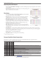
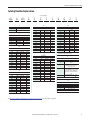
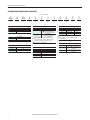
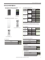
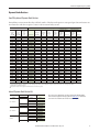
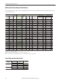
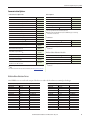
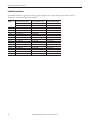
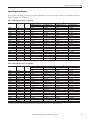
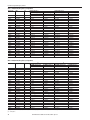
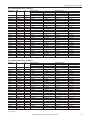
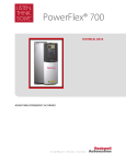
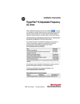
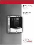
PowerFlex 70 Adjustable Frequency AC Drive
Additional Resources
These documents contain additional information concerning related products from Rockwell Automation.
Resource
Description
PowerFlex 70 Adjustable Frequency AC Drive User Manual, publication 20A-UM001
Provides the basic information needed to start up and troubleshoot the PowerFlex®
70 Adjustable Frequency AC Drive.
PowerFlex 70 and 700 Reference Manual - Volume 1, publication PFLEX-RM001
Provides detailed information for specifications and dimensions, operation, and
dynamic brake selection for the drive.
PowerFlex 70 Adjustable Frequency AC Drive Installation Instructions, publication 20A-IN009
Provides the five basic steps needed to install and perform a basic startup of the
PowerFlex 70 drive.
Wiring and Grounding Guidelines for Pulse Width Modulated (PWM) AC Drives,
publication DRIVES-IN001
Provides the basic information needed to properly wire and ground Pulse Width
Modulated (PWM) AC drives.
Industry Installation Guidelines for Pulse Width Modulated (PWM) AC Drives,
publication DRIVES-AT003
Provides basic information for enclosure systems and environmental/location
considerations (to help protect against environmental contaminants), and power and
grounding considerations needed to properly install AC drives.
Safety Guidelines for the Application, Installation and Maintenance of Solid State Control,
publication SGI-1.1
Provides general guidelines for the application, installation, and maintenance of
solid-state control.
Preventive Maintenance of Industrial Control and Drive System Equipment,
publication DRIVES-TD001
Provides a guide to performing preventive maintenance.
Guarding Against Electrostatic Damage, publication 8000-4.5.2
Provides practices for guarding against Electrostatic damage (ESD)
Industrial Automation Wiring and Grounding Guidelines, publication 1770-4.1
Provides general guidelines for installing a Rockwell Automation industrial system.
Product Certifications website, http://www.ab.com
Provides declarations of conformity, certificates, and other certification details.
You can view or download publications at http://www.rockwellautomation.com/literature/. To order paper copies of
technical documentation, contact your local Allen-Bradley distributor or Rockwell Automation sales representative.
Product Overview
PowerFlex 70 drives are designed to worldwide standards providing out-of-thebox performance around the globe. Available ratings include these options:
• 0.5…25 Hp output at 240V AC input
• 0.5…50 Hp output at 480V AC input
• 0.5…50 Hp output at 600V AC input
The PowerFlex 70 drive can be used with a full featured LCD human interface
module (HIM) that provides multilingual text for startup, metering,
programming, and troubleshooting.
The PowerFlex 70 can be programmed for either volts per hertz, sensorless
vector, or vector control with FORCE™ Technology to cover a wide range of
applications from fans to extruders.
Optional internal communication modules provide fast and efficient control and/or data exchange with host controllers
over popular interfaces. These interfaces include: DeviceNet, EtherNet, ControlNet, remote I/O, serial communications,
and other open control and communication networks. Computer tools such as DriveExplorer™ and DriveTools™ SP assist
with programming, monitoring, and troubleshooting the PowerFlex 70.
2
Rockwell Automation Publication 20A-TD001J-EN-P - July 2014
PowerFlex 70 Adjustable Frequency AC Drive
Flexible Packaging and Mounting
• IP20, NEMA / UL Type 1 – For conventional mounting inside or outside a control cabinet. Conduit plate is
vertically removable for easy installation and replacement without disturbing conduit.
• IP66, NEMA / UL Type 4X/12 (indoor use) – For mounting directly in the production environment. Listed by
UL to resist dust, dirt, other contaminants, and to survive high-pressure water spray. Also certified by NSF
International to assure conformity with international food equipment standards.
• Flange Type – For mounting heatsink through back of an enclosure, thus removing a large portion of the heat inside
a cabinet. The backside is rated IP66, NEMA / UL Type 4X/12 for both indoor and outdoor use.
• Zero-Stacking™ - Drives can be mounted directly next to one another with no reduction of ambient temperature
rating (50 °C [122 °F] for IP20, NEMA / UL Type 1 and Flange Mount; 40 °C [104 °F] for IP66, NEMA / UL
Type 4X/12).
Space Saving Hardware Features
• Integral electromagnetic compatibility (EMC) filtering provides a compact, all-in-one package solution for meeting
EMC requirements, including CE in Europe.
• Integral dynamic brake transistor delivers a cost-effective means of switching regenerative energy without costly
external chopper circuits.
• Internal dynamic brake resistor requires no extra panel space, and supplies a large amount of braking torque for short
periods.
Easy to Use Human Interface Tools
The PowerFlex 7-Class AC drives provide common human interface tools that are familiar and easy to use. These include
the LCD human interface modules and computer-based configuration tools.
The LCD HIMs provide these features and functions:
• Large and easy to read 7-line x 21-character backlit display
• Variety of languages (English, French, German, Italian, Spanish, Portuguese, Dutch)
• Alternate function keys for shortcuts to common tasks
• ‘Calculator-like’ number pad for fast and easy data entry (full numeric version only)
• Control keys for local start, stop, speed, and direction
Remote versions for panel mount application
Rockwell Automation Publication 20A-TD001J-EN-P - July 2014
3
PowerFlex 70 Adjustable Frequency AC Drive
Outstanding Control and Performance
• Vector Control with FORCE™ Technology (1) provides outstanding torque and speed regulation, with or without
encoder feedback.
• Sensorless Vector Control develops high torque over a wide speed range, and
adapts to individual motor characteristics.
Drives Features
• Fast acting Current Limit and Bus Voltage Regulation result in maximum
acceleration and deceleration without tripping.
• Flying Start delivers smooth connection into rotating loads, regardless of
commanded direction, without the need for any speed feedback device.
• PI Control can eliminate the need for a separate process loop controller.
• Inertia Ride-Through offers tripless operation during a prolonged power
outage by using the rotating energy stored in high-inertia, low-friction loads.
• User Sets, allowing up to three complete sets of parameter data, can be
individually loaded for different batch processes.
• Slip compensation delivers minimum of 0.5% open loop speed regulation
across a wide speed range, eliminating the need for speed feedback devices in
some applications.
• Safe Off Option (1), the first offering available within the DriveGuard® series of safety solutions, prevents a drive
from delivering rotational energy to motors by integrating a safety circuit with the drive’s power switching signals.
This solution meets EN ISO 13849-1, Category 3.
• Droop Control (1) for load sharing applications.
• Sleep/Wake Control (1) for analog control of start and stop.
(1)
The feature is available only for enhanced control.
Unsurpassed Capability in Network Communications
BACnet
DeviceNet
ControlNet
EtherNet/IP
Remote I/O (1)
RS-485 DF1
Profibus DP
LonWorks
Modbus RTU
Modbus TCP
Metasys N2
Siemens P1 FLN
PowerFlex drives are fully compatible with the wide variety of Allen-Bradley® DPI™ (drive peripheral interface)
communication adapters, offering the following benefits.
X
X
X
X X
X
X X
X X
X
X
X
X
X
X
X
X
X X
X X
X
X
X
X X
X
X X
X
X
X X
X
X X
X X
Description
Unconnected Messaging permits other network devices (for example, PanelView™) to communicate directly to a drive without routing the
communication through the network scanner.
Adapter Routing -- Plug PC into one drive and talk to other Allen-Bradley drives on same network, without being routed through network scanner.
X Access to 100% of all parameters over the network.
AutoBaud capability makes initial connections less problematic.
Change Of State significantly reduces network traffic by configuring control messages to be sent only upon customer defined states. Very flexible
configuration for each node (for example, reference must change by more than 5%).
Peer Control provides master slave type control between drives, where one or more slave drives (consumers) can run based on the status of a master
drive (producer), that can also significantly reduce network traffic.
Automatic Device Replacement (ADR) saves significant time and effort when replacing a drive, by allowing the scanner to be configured to
automatically detect a new drive and download the required parameter settings.
X Flexible Fault Configuration – Adapters can be programmed to take fault-based actions such as ramp to stop, cost to stop, and hold last state, as
well as send user configurable logic control and speed reference values. In addition, different actions can be taken based on whether the network
experienced a serious problem (broken cable) versus a network idle condition (PLC set to ‘Program.’
(1) The remote I/O has silver series status. For more information, refer to http://www.ab.com/silver.
4
Rockwell Automation Publication 20A-TD001J-EN-P - July 2014
PowerFlex 70 Adjustable Frequency AC Drive
Catalog Number Explanation
Position Number
1-3
4
5-7
8
9
10
11
20A
B
2P2
a
b
c
12
13
14
A
3
A
d
e
f
15
Y
Y
N
N
C
0
g
h
i
j
k
l
a
c3
c5
Drive
ND Rating
ND Rating
Code
Type
20A
PowerFlex 70
400V, 50 Hz Input
Code
Amps
kW (Hp)
1P3
1.3
0.37 (0.5)
2P1
2.1
3P5
16
600V, 60 Hz Input
Frame
Code
Amps
kW (Hp)
A
0P9
0.9
0.37 (0.5)
0.75 (1.0)
A
1P7
1.7
0.75 (1.0)
A
3.5
1.5 (2.0)
A
2P7
2.7
1.5 (2.0)
A
5P0
5.0
2.2 (3.0)
B
3P9
3.9
2.2 (3.0)
B
8P7
8.7
4.0 (5.0)
B
6P1
6.1
4.0 (5.0)
B
011
11.5
5.5 (7.5)
C
9P0
9.0
5.5 (7.5)
C
015
15.4
7.5 (10)
C
011
11
7.5 (10)
C
022
22
11 (15)
D
017
17
11 (15)
D
030
30
15 (20)
D
022
22
15 (20)
D
037
37
18.5 (25)
D
027
27
18.5 (25)
D
043
43
22 (30)
D
032
32
22 (30)
D
ND Rating
060
60
30 (40)
E
041
41
30 (40)
E
208V, 60 Hz Input
072
72
37 (50)
E
052
52
37 (50)
E
b
Voltage Rating
Code
Voltage
Ph.
B
240V AC
3
C
400V AC
3
D
480V AC
3
E
600V AC
3
c1
Code
Amps
kW (Hp)
Frame
2P2
2.5
0.37 (0.5)
A
4P2
4.8
0.75 (1.0)
A
6P8
7.8
1.5 (2.0)
B
9P6
11
2.2 (3.0)
B
015
17.5
4.0 (5.0)
C
022
25.3
5.5 (7.5)
D
028
32.2
7.5 (10)
D
042
43
11 (15)
D
054
62.1
15 (20)
E
070
78.2
18.5 (25)
E
c2
A
CE certification testing has not been
performed on 600V class drives.
c4
ND Rating
d
480V, 60 Hz Input
Code
Amps
kW (Hp)
1P1
1.1
0.37 (0.5)
Enclosure
Frame
A
2P1
2.1
0.75 (1.0)
A
3P4
3.4
1.5 (2.0)
A
5P0
5.0
2.2 (3.0)
B
8P0
8.0
3.7 (5.0)
B
011
11
5.5 (7.5)
C
014
14
7.5 (10)
C
11 (15)
D
D
022
22
ND Rating
027
27
15 (20)
240V, 60 Hz Input
034
34
18.5 (25)
D
040
40
22 (30)
D
Frame
Frame
Code
Amps
kW (Hp)
2P2
2.2
0.37 (0.5)
A
052
52
30 (40)
E
4P2
4.2
0.75 (1.0)
A
065
65
37 (50)
E
6P8
6.8
1.5 (2.0)
B
9P6
9.6
2.2 (3.0)
B
015
15.3
4.0 (5.0)
C
022
22
5.5 (7.5)
D
028
28
7.5 (10)
D
042
42
11 (15)
D
054
54
15 (20)
E
070
70
18.5 (25)
E
Code
Enclosure
A
Panel Mount - IP 20, NEMA/UL
Type 1
C
Wall/Machine Mount = IP66,
NEMA/UL Type 4X/12 for
indoor use only
F
Flange Mount - Front Chassis =
IP 20, NEMA/UL Type 1; Rear
Heatsink = IP66, NEMA/UL
Type 4X/12 for indoor/outdoor
use
G
Wall/Machine Mount - IP54,
NEMA/UL Type 12
Only available on Frame E.
e
HIM
Code
Interface Module
0
Blank Cover
3
Full Numeric LCD
5
Prog. Only LCD
Only available with NEMA 4X, option C.
See Catalog Number Explanation (continued) on page 6 for more drive options.
Rockwell Automation Publication 20A-TD001J-EN-P - July 2014
5
PowerFlex 70 Adjustable Frequency AC Drive
Catalog Number Explanation (continued)
Position Number
1-3
4
5-7
8
9
10
11
12
13
14
15
16
20A
B
2P2
A
3
A
Y
Y
N
N
C
0
a
b
c
d
e
f
g
h
i
j
k
l
f
i
k
Documentation
Emission Class
Control & I/O
Code
Type
A
Manual
N
No Manual
g
Code
Rating
Code
Control
Safe-Off
A
Filtered
A & B Frames (Optional)
C, D, & E Frames (Standard)
N
Standard
N/A
C
Enhanced
No
G
Enhanced
Yes
N
Not Filtered
A & B Frames (Optional)
C, D, & E Frames
Brake IGBT
Code
w/Brake IGBT
Y
Yes
600V Frames A through D available only
without filter (Cat. Code N). 600V Frame E
available only with filter (Cat. Code A).
No longer available for sale.
Not available as factory installed option for
600V ratings.
l
Increases size to Frame B.
h
Feedback
j
Internal Brake Resistor
6
Code
w/Resistor
Y
Yes
Code
Network Type
N
No
C
ControlNet (Coax)
Comm Slot
D
DeviceNet
E
N
EtherNet/IP
None
Rockwell Automation Publication 20A-TD001J-EN-P - July 2014
Code
Feedback
0
No Feedback - Enhanced
Control
1
5V/12V Encoder w/Enhanced
Control
PowerFlex 70 Adjustable Frequency AC Drive
Factory Installed Options
Human Interface and Wireless Interface Modules
IP20, NEMA/UL Type 1 and Flange Type Drives
(Pos. e)
Internal Dynamic Brake Resistors
Drive Input
Voltage
200…240V AC
22
Cat. Code: 3
LCD Display, Full
Numeric Keypad
115
380…480V AC
62
IP66, NEMA/UL Type 4X/12 Drives
(Position e)
600V AC
Frame
Ω
62
Cat. Code: 0
No HIM (Blank Plate)
Cat. Code
Brake Resistance
115
(Position h)
A
Y
B
Y
C
Y
D
Y
E
Not Available
A
Y
B
Y
C
Y
D
Y
E
Not Available
A
Y
B
Y
C
Y
D and E
Not Available
These resistors have a limited duty cycle. Refer to the PowerFlex
Dynamic Braking Selection Guide to determine if an internal
resistor will be sufficient. An external resistor may be required.
Internal EMC Filter
Cat. Code: 0
No HIM (Blank)
Cat. Code: 3
LCD Display, Full Numeric Keypad
Cat. Code
Drive Input
Voltage
200...240V AC
380...480V AC
CE Filter
Frame
Optional
B
Standard
C
Standard
D
Optional
B
Standard
C
Standard
D
Standard
E
(Position i)
A
A
Internal CE filters are not available for PowerFlex 70 A Frame drives. If an
A Frame rating is ordered with an internal filter option, it will be supplied in
a B Frame.
Cat. Code: 5
LCD Display, Programmer Only
Internal Communication Adapters
Documentation
Cat. Code
Description
Cat. Code
Description
(Position f)
(Position j)
ControlNet™ Communication Adapter (Coax)
C
D
E
English User Manual, Multi-Language Quick Start
A
DeviceNet™ Communication Adapter
No User Manual
N
EtherNet/IP™ Communication Adapter
Control Options
Cat. Code
Description
(Position k)
Enhanced Control without DriveGuard
C
Enhanced Control with DriveGuard
G
Feedback Options
Cat. Code
Description
None
5V/12V Encoder
Rockwell Automation Publication 20A-TD001J-EN-P - July 2014
(Position l)
0
1
7
PowerFlex 70 Adjustable Frequency AC Drive
User Installed Options
Human Interface and Wireless Interface Modules
No HIM (Blank Plate)
20-HIM-A0
LCD Display, Full
Numeric Keypad
20-HIM-A3
Remote (Panel Mount)
LCD Display, Full
Numeric Keypad
20-HIM-C3S
Remote (Panel Mount)
LCD Display,
Programmer Only
20-HIM-C5S
LCD Display,
Programmer Only
20-HIM-A5
Enhanced LCD Display,
Full Numeric Keypad
20-HIM-A6
Enhanced LCD Display,
Full Numeric Keypad
20-HIM-A6S
Handheld/Local
(Drive Mount)
Remote (Panel
Mount) IP66,
NEMA/UL Type
4x/12
Human Interface Module Accessories
Description
Cat. No.
20-HIM-B1
Bezel Kit for LCD HIMs, NEMA/UL Type 1 ‡
Cat. No.
Cat. No.
No HIM (Blank Plate)
20-HIM-A0
–
LCD Display, Full Numeric Keypad
20-HIM-A3
20-HIM-C3S ‡
0.33 Meters (1.1 Feet)
1202-H03
LCD Display, Programmer Only
20-HIM-A5
20-HIM-C5S ‡
1 Meter (3.3 Feet)
1202-H10
Enhanced LCD Display, Full Numeric Keypad
20-HIM-A6
20-HIM-A6S
3 Meter (9.8 Feet)
1202-H30
9 Meter (29.5 Feet)
1202-H90
Description
For indoor use only.
‡ Includes a 1202-C30 interface cable, 3 m (9.8 ft), for connection to drive.
PowerFlex HIM Interface Cable, 1 m (39 in)
♣
20-HIM-H10
Cable Kit (Male-Female)
Comm Option Cable Kit
0.33 Meters (1.1 Feet)
1202-C03
1 Meter (3.3 Feet)
1202-C10
3 Meter (9.8 Feet)
1202-C30
9 Meter (29.5 Feet)
DPI Cable Kit with Connectors, Tools and 100 m (328 ft.)
Cable
DPI Cable Connector Kit
DPI/SCANport™ One to Two Port Splitter Cable
1202-C90
1202-CBLKIT-100M
1202-TB-KITSET
1203-S03
‡ Includes a 1202-C30 interface cable (3 meters) for connection to drive.
♣ Required only when HIM is used as handheld or remote.
Required in addition to 20-HIM-H10 for distances up to a total maximum
of 10 Meters (32.8 Feet).
8
Rockwell Automation Publication 20A-TD001J-EN-P - July 2014
PowerFlex 70 Adjustable Frequency AC Drive
Dynamic Brake Resistors
Small Duty Internal Dynamic Brake Resistors
Limited duty resistors mount directly to the back surface of the drive and require no extra panel space. Internal resistors are
non-destructive and do not require a resistor overheat external safety circuit.
.
PowerFlex 70 AC Drive
Heavy
Duty
kW (Hp)
Normal
Duty
kW (Hp)
Small Duty Internal DB Resistor
Min DB
Res
Ohms
±10%
Resistance
Part Number
Ohms ±5%
Continuous
Power
kW
Max
Energy
kJ
Max
Braking
Torque
% of ND
Motor
Application Type 1
Braking
Torque
% of ND
Motor
Duty Cycle
Application Type 2
Braking
Torque
% of ND
Motor
Duty Cycle
200…240 Volt AC Input Drives
0.37 (0.5)
0.25 (0.33)
33
20AB-DB1-A
62
0.048
8.3
307%
100%
25.9%
150%
0.75 (1.0)
0.55 (0.75)
33
20AB-DB1-A
62
0.048
7.3
300%
100%
12.8%
150%
17.3%
8.5%
1.5 (2.0)
1.1 (1.5)
33
20AB-DB1-B
62
0.028
0.8
160%
100%
3.7%
150%
2.5%
2.2 (3.0)
1.5 (2.0)
33
20AB-DB1-B
62
0.028
0.8
109%
100%
2.5%
109%
2.3%
4.0 (5.0)
3.0 (3.0)
30
20AB-DB1-C
62
0.040
0.8
60%
60%
3.3%
N/A
N/A
5.5 (7.5)
4.0 (5.0)
21
20AB-DB1-D
22
0.036
0.9
117%
100%
1.3%
117%
1.1%
7.5 (10)
5.5 (7.5)
21
20AB-DB1-D
22
0.036
0.9
86%
86%
1.1%
N/A
N/A
400…480 Volt AC Input Drives
0.37 (0.5)
0.25 (0.33)
68
20AD-DB1-A
115
0.048
8.3
320%
100%
25.9%
150%
17.3%
0.75 (1.0)
0.55 (0.75)
20AD-DB1-A
115
0.048
9.0
259%
100%
12.8%
150%
8.5%
1.5 (2.0)
1.1 (1.5)
68
68
20AD-DB1-A
115
0.048
2.4
243%
100%
6.4%
150%
4.3%
2.2 (3.0)
1.5 (2.0)
68
20AD-DB1-B
115
0.028
0.9
206%
100%
2.5%
150%
1.7%
4.0 (5.0)
3.0 (3.0)
68
20AD-DB1-B
115
0.028
0.9
129%
100%
1.4%
129%
1.1%
5.5 (7.5)
4.0 (5.0)
74
20AD-DB1-C
115
0.04
0.9
94%
94%
1.5%
N/A
N/A
7.5 (10)
5.5 (7.5)
74
20AD-DB1-C
115
0.04
0.9
69%
69%
1.5%
N/A
N/A
11 (15)
7.5 (10)
44
20AD-DB1-D
62
0.036
0.8
87%
87%
0.8%
N/A
N/A
15 (20)
11 (15)
31
20AD-DB1-D
62
0.036
0.8
64%
64%
0.8%
N/A
N/A
17.3%
500…600 Volt AC Input Drives
0.37 (0.5)
0.25 (0.33)
117
20AD-DB1-A
115
0.048
8.3
287%
100%
25.9%
150%
0.75 (1.0)
0.55 (0.75)
20AD-DB1-A
115
0.048
9.0
263%
100%
12.8%
150%
8.5%
1.5 (2.0)
1.1 (1.5)
117
117
20AD-DB1-A
115
0.048
2.4
243%
100%
6.4%
150%
4.3%
2.2 (3.0)
1.5 (2.0)
117
20AD-DB1-B
115
0.028
0.9
202%
100%
2.5%
150%
1.7%
4.0 (5.0)
3.0 (3.0)
80
20AD-DB1-B
115
0.028
0.9
193%
100%
1.4%
150%
0.9%
5.5 (7.5)
4.0 (5.0)
80
20AD-DB1-C
115
0.04
0.9
147%
100%
1.5%
147%
1.0%
7.5 (10)
5.5 (7.5)
80
20AD-DB1-C
115
0.04
0.9
108%
100%
1.1%
108%
1.0%
11 (15)
7.5 (10)
48
N/A
N/A
N/A
N/A
N/A
N/A
N/A
N/A
N/A
15 (20)
11 (15)
48
N/A
N/A
N/A
N/A
N/A
N/A
N/A
N/A
N/A
Duty cycle listed is based on full speed to zero speed deceleration. For constant regen at full speed, duty cycle capability is half of what is listed. Application
Type 1 represents maximum capability up to 100% braking torque where possible. Application Type 2 represents more than 100% braking torque where
possible, up to a maximum of 150%.
Always check resistor ohms against minimum resistance for drive being used.
Internal Dynamic Brake Resistor Kits
Drive Input
Voltage
Brake Resistance
Cat. No.
A
20AB-DB1-A
62
B
20AB-DB1-B
C
20AB-DB1-C
22
D
20AB-DB1-D
E
Not Available
200…240V AC
A
20AD-DB1-A
115
B
20AD-DB1-B
C
20AD-DB1-C
62
D
20AD-DB1-D
E
Not Available
380…480V AC
600V AC
Frame
Ω
115
A
20AD-DB1-A
B
20AD-DB1-B
C
20AD-DB1-C
D and E
Not Available
These resistors have a limited duty cycle. Refer to the PowerFlex Dynamic Braking
Resistor Calculator Application Technique, publication PFLEX-AT001, to determine if
an internal resistor is sufficient. An external resistor may be required.
Rockwell Automation Publication 20A-TD001J-EN-P - July 2014
9
PowerFlex 70 Adjustable Frequency AC Drive
Medium Duty External Dynamic Brake Resistors
These resistors provide a larger duty cycle capability than the internal type. Includes an internal thermal switch for use in
external safety circuit.
PowerFlex 70 AC Drive
Normal
Duty
kW (Hp)
Heavy
Duty
kW (Hp)
Medium Duty External DB Resistor
Resistance
Min DB
Res
Ohms
±10%
Ohms
±5%
Part Number
Application Type 1
Continuous Max
Power
Energy
kJ
kW
Max Braking
Torque
% of ND Motor
Braking Torque
% of ND Motor
Duty
Cycle
Application Type 2
Braking Torque
% of ND Motor
Duty
Cycle
200…240 Volt ac Input Drives
0.37 (0.5)
0.25 (0.33) 33
AK-R2-091P500 91
0.086
17
293%
100%
46%
150%
31%
0.75 (1.0)
0.55 (0.75) 33
AK-R2-091P500 91
0.086
17
218%
100%
23%
150%
15%
1.5 (2.0)
1.1 (1.5)
33
AK-R2-091P500 91
0.086
17
109%
100%
11%
109%
11%
2.2 (3.0)
1.5 (2.0)
33
AK-R2-047P500 47
0.166
33
144%
100%
15%
144%
11%
4.0 (5.0)
3.0 (3.0)
30
AK-R2-047P500 47
0.166
33
79%
79%
11%
N/A
N/A
5.5 (7.5)
4.0 (5.0)
23
AK-R2-030P1K2 30
0.26
52
90%
90%
10%
N/A
N/A
7.5 (10)
5.5 (7.5)
23
AK-R2-030P1K2 30
0.26
52
66%
66%
10%
N/A
N/A
400…480 Volt ac Input Drives
0.37 (0.5)
0.25 (0.33) 68
AK-R2-360P500 360
0.086
17
305%
100%
47%
150%
31%
0.75 (1.0)
0.55 (0.75) 68
AK-R2-360P500 360
0.086
17
220%
100%
23%
150%
15%
1.5 (2.0)
1.1 (1.5)
68
AK-R2-360P500 360
0.086
17
110%
100%
12%
110%
11%
2.2 (3.0)
1.5 (2.0)
68
AK-R2-120P1K2 120
0.26
52
197%
100%
24%
150%
16%
4.0 (5.0)
3.0 (3.0)
68
AK-R2-120P1K2 120
0.26
52
124%
100%
13%
124%
10%
5.5 (7.5)
4.0 (5.0)
74
AK-R2-120P1K2 120
0.26
52
90%
90%
10%
N/A
N/A
AK-R2-120P1K2 120
7.5 (10)
5.5 (7.5)
74
11 (15) ‡
7.5 (10) ‡
44
‡
60
15 (20) ‡
11 (15) ‡
31
‡
60
0.26
52
66%
66%
10%
N/A
N/A
0.52
104
90%
90%
10%
N/A
N/A
0.52
104
66%
66%
10%
N/A
N/A
500…600 Volt ac Input Drives
0.37 (0.5)
0.25 (0.33) 117
AK-R2-360P500 360
0.086
17
274%
100%
46%
150%
31%
0.75 (1.0)
0.55 (0.75) 117
AK-R2-360P500 360
0.086
17
251%
100%
23%
150%
15%
1.5 (2.0)
1.1 (1.5)
117
AK-R2-360P500 360
0.086
17
172%
100%
11%
150%
8%
2.2 (3.0)
1.5 (2.0)
117
AK-R2-120P1K2 120
0.26
52
193%
100%
24%
150%
16%
4.0 (5.0)
3.0 (3.0)
80
AK-R2-120P1K2 120
0.26
52
185%
100%
13%
150%
9%
5.5 (7.5)
4.0 (5.0)
80
AK-R2-120P1K2 120
0.26
52
141%
100%
9%
141%
7%
7.5 (10)
5.5 (7.5)
80
AK-R2-120P1K2 120
0.26
52
103%
100%
7%
103%
7%
11 (15) ‡
7.5 (10) ‡
48
‡
60
0.52
104
141%
100%
9%
141%
7%
15 (20) ‡
11 (15) ‡
48
‡
60
0.52
104
103%
100%
7%
103%
7%
Duty cycle listed is based on full speed to zero speed deceleration. For constant regen at full speed, duty cycle capability is half of what is listed. Application
Type 1 represents maximum capability up to 100% braking torque where possible. Application Type 2 represents more than 100% braking torque where
possible, up to a maximum of 150%.
Always check resistor ohms against minimum resistance for drive being used.
‡ For 11 and 15 kW (15 and 20 Hp) applications, use two 7.5 kW (10 Hp) size resistors wired in parallel.
External Dynamic Brake Resistor Kits
Drive Input
Voltage
200…240V ac
480…600V ac
10
Continuous
Power
Brake Resistance
W
Ω
Cat. No.
30
260
AK-R2-030P1K2
47
166
AK-R2-047P500
91
86
AK-R2-091P500
120
260
AK-R2-120P1K2
360
86
AK-R2-360P500
Rockwell Automation Publication 20A-TD001J-EN-P - July 2014
PowerFlex 70 Adjustable Frequency AC Drive
Communication Options
Communication Option Kits
Other Options
Description
Cat. No.
Description
Cat. No.
BACnet MS/TP RS485 Communication Adapter
20-COMM-B
DriveGuard Safe-Off Board §
20A-DG01
ControlNet Communication Adapter (Coax)
20-COMM-C
5V/12V Encoder §
20A-ENC-1
DeviceNet Communication Adapter
20-COMM-D
115V ac Interface
AK-M9-115VAC-1
®
EtherNet/IP Communication Adapter
20-COMM-E
Frame E Flange Gasket
HVAC Communication Adapter
20-COMM-H
Service Connection Board
CANopen Communication Adapter
20-COMM-K
LonWorksCommunication Adapter
20-COMM-L
Modbus/TCP Communication Adapter
20-COMM-M
§ Works only with PowerFlex 70 Enhanced Control.
Provides temporary DPI/HIM connection for NEMA/UL Type 1 and Flange
drives with cover removed.
PROFIBUS DP Communication Adapter
20-COMM-P
ControlNet Communication Adapter (Fiber)
20-COMM-Q
Remote I/O Communication Adapter
1
20-COMM-R
AK-M9-GASKET1-E4
SK-M9-SCB1
Terminators
Description
Cat. No.
RS485 DF1 Communication Adapter
20-COMM-S
for use with 3.7 kW (5 Hp) & below drives
1204-TFA1
External Communications Kit Power Supply
20-XCOMMAC-PS1
for use with 1.5 kW (2 Hp) & up drives
1204-TFB2
DPI External Communications Kit
20-XCOMMDC-BASE
Refer to Appendix A of publication
information.
External DPI I/O Option Board
20-XCOMMIO-OPT1
Compact I/O Module (3 Channel)
1769-SM1
Serial Null Modem Adapter
1203-SNM
Smart Self-powered Serial Converter (RS232) includes
1203-SFC and 1202-C10 Cables
1203-SSS
Universal Serial Bus™ (USB) Converter includes 2m USB,
20-HIM-H10 & 22-HIM-H10 Cables
DRIVES-IN001 for selection
Reflected Wave Reduction Modules
Description
Cat. No.
1204-RWC-17-A
17A with Common Mode Choke
9A without Choke, Book Mount
1204-RWR2-09-B
9A without Choke, Stack Mount
1204-RWR2-09-C
1203-USB
For use only with DPI External Communications Kits 20-XCOMM-DCBASE.
1 The remote I/O has silver series status. For more information, refer to http://www.ab.com/silver.
Refer to Appendix A of publication
information.
DRIVES-IN001 for selection
Reflective Wave Reduction Devices
1321-RWR devices are used at the output of the drive to reduce dv/dt and motor terminal peak voltages
480V, 60 Hz, Three-phase
Drive Cat. No.
kW (Hp)
20AD1P1-ND
0.37 (0.5)
20AD2P1-ND
0.75 (1.0)
20AD3P4-ND
1.5 (2.0)
20AD5P0-ND
2.2 (3.0)
20AD8P0-ND
4.0 (5.0)
20AD011-ND
5.5 (7.5)
20AD014-ND
7.5 (10)
20AD022-ND
11 (15)
20AD027-ND
15 (20)
20AD034-ND
18.5 (25)
20AD040-ND
22 (30)
20AD052-ND
30 (40)
20AD065-ND
37 (50)
RWR Filter Cat. No.
–
–
–
–
1321-RWR8-DP
1321-RWR12-DP
1321-RWR18-DP
1321-RWR25-DP
1321-RWR35-DP
1321-RWR35-DP
1321-RWR45-DP
1321-RWR55-DP
1321-RWR80-DP
600V, 60 Hz, Three-phase
Drive Cat. No.
kW (Hp)
20AE0P9-ND
0.37 (0.5)
20AE1P7-ND
0.75 (1.0)
20AE2P7-ND
1.5 (2.0)
20AE3P9-ND
2.2 (3.0)
20AE6P1-ND
4.0 (5.0)
20AE9P0-ND
5.5 (7.5)
20AE011-ND
7.5 (10)
20AE017-ND
11 (15)
20AE022-ND
15 (20)
20AE027-ND
18.5 (25)
20AE032-ND
22 (30)
20AE041-ND
30 (40)
20AE052-ND
37 (50)
Rockwell Automation Publication 20A-TD001J-EN-P - July 2014
RWR Filter Cat. No.
–
–
–
–
1321-RWR8-EP
1321-RWR12-EP
1321-RWR18-EP
1321-RWR25-EP
1321-RWR35-EP
1321-RWR45-EP
1321-RWR55-EP
1321-RWR80-EP
1321-RWR100-EP
11
PowerFlex 70 Adjustable Frequency AC Drive
Isolation Transformers
For installations that have specific types of AC supply configurations or require drive protection due to AC line
disturbances, isolation transformers are available.
Motor Rating
kW (Hp)
0.25 (0.33)
0.37 (0.5)
0.55 (0.75)
0.75 (1.0)
1.1 (1.5)
1.5 (2.0)
2.2 (3.0)
4.0 (5.0)
5.5 (7.5)
7.5 (10)
11 (15)
15 (20)
18.5 (25)
22 (30)
30 (40)
37 (50)
12
240V, 60 Hz, Three-phase, 240V
Primary and 240V Secondary
IP32 (NEMA / UL Type 3R)
Cat. No.
1321-3TW005-AA
1321-3TW005-AA
1321-3TW005-AA
1321-3TW005-AA
1321-3TW005-AA
1321-3TW005-AA
1321-3TW005-AA
1321-3TW007-AA
1321-3TW011-AA
1321-3TW014-AA
1321-3TW020-AA
1321-3TW027-AA
1321-3TW034-AA
–
–
–
460V, 60 Hz, Three-phase, 460V
Primary and 460V Secondary
IP32 (NEMA / UL Type 3R)
Cat. No.
1321-3TW005-BB
1321-3TW005-BB
1321-3TW005-BB
1321-3TW005-BB
1321-3TW005-BB
1321-3TW005-BB
1321-3TW005-BB
1321-3TW007-BB
1321-3TW011-BB
1321-3TW014-BB
1321-3TW020-BB
1321-3TW027-BB
1321-3TW034-BB
1321-3TW040-BB
1321-3TW051-BB
1321-3TH063-BB
575V, 60 Hz, Three-phase 575V
Primary and 575V Secondary
IP32 (NEMA / UL Type 3R)
Cat. No.
–
–
–
1321-3TW005-CC
–
1321-3TW005-CC
1321-3TW005-CC
1321-3TW007-CC
1321-3TW011-CC
1321-3TW014-CC
1321-3TW020-CC
1321-3TW027-CC
1321-3TW034-CC
1321-3TW040-CC
1321-3TW051-CC
1321-3TH063-CC
Rockwell Automation Publication 20A-TD001J-EN-P - July 2014
PowerFlex 70 Adjustable Frequency AC Drive
Input/Output Line Reactors
For impedance matching, protection from AC line disturbances or motor protection, reactors are available for both the
input and output sides of the drive.
Table 1 - 240V, 60 Hz, Three-phase, 3% Impedance
Drive Cat. No.
20AB2P2
20AB2P2
20AB4P2
20AB4P2
20AB6P8
20AB6P8
20AB9P6
20AB9P6
20AB015
20AB015
20AB022
20AB022
20AB028
20AB028
20AB042
20AB042
20AB054
20AB054
20AB070
20AB070
Duty
Heavy Duty
Normal Duty
Heavy Duty
Normal Duty
Heavy Duty
Normal Duty
Heavy Duty
Normal Duty
Heavy Duty
Normal Duty
Heavy Duty
Normal Duty
Heavy Duty
Normal Duty
Heavy Duty
Normal Duty
Heavy Duty
Normal Duty
Heavy Duty
Normal Duty
Hp
0.33
0.5
0.75
1
1.5
2
2
3
3
5
5
7.5
7.5
10
10
15
15
20
20
25
Input Line Reactor (1)
IP00 (NEMA / UL Type Open)
Cat. No.
1321-3R2-D
1321-3R2-D
1321-3R4-A
1321-3R4-A
1321-3R8-B
1321-3R8-A
1321-3R8-A
1321-3R12-A
1321-3R12-A
1321-3R18-A
1321-3R18-A
1321-3R25-A
1321-3R25-A
1321-3R35-A
1321-3R35-A
1321-3R45-A
1321-3R45-A
1321-3R55-A
1321-3R55-A
1321-3R80-A
IP11 (NEMA / UL Type 1)
Cat. No.
1321-3RA2-D
1321-3RA2-D
1321-3RA4-A
1321-3RA4-A
1321-3RA8-B
1321-3RA8-A
1321-3RA8-A
1321-3RA12-A
1321-3RA12-A
1321-3RA18-A
1321-3RA18-A
1321-3RA25-A
1321-3RA25-A
1321-3RA35-A
1321-3RA35-A
1321-3RA45-A
1321-3RA45-A
1321-3RA55-A
1321-3RA55-A
1321-3RA80-A
Output Line Reactor (1)
IP00 (NEMA / UL Type Open)
Cat. No.
1321-3R2-D
1321-3R2-D
1321-3R4-A
1321-3R4-A
1321-3R8-A
1321-3R8-A
1321-3R12-A
1321-3R12-A
1321-3R18-A
1321-3R18-A
1321-3R25-A
1321-3R25-A
1321-3R35-A
1321-3R35-A
1321-3R45-A
1321-3R45-A
1321-3R55-A
1321-3R55-A
1321-3R80-A
1321-3R80-A
IP11 (NEMA / UL Type 1)
Cat. No.
1321-3RA2-D
1321-3RA2-D
1321-3RA4-A
1321-3RA4-A
1321-3RA8-A
1321-3RA8-A
1321-3RA12-A
1321-3RA12-A
1321-3RA18-A
1321-3RA18-A
1321-3RA25-A
1321-3RA25-A
1321-3RA35-A
1321-3RA35-A
1321-3RA45-A
1321-3RA45-A
1321-3RA55-A
1321-3RA55-A
1321-3RA80-A
1321-3RA80-A
(1) Input line reactors were sized based on the NEC fundamental motor amps. Output line reactors were sized based on the VFD rated output currents.
Table 2 - 240V, 60 Hz, Three-phase, 5% Impedance
Drive Cat. No.
20AB2P2
20AB2P2
20AB4P2
20AB4P2
20AB6P8
20AB6P8
20AB9P6
20AB9P6
20AB015
20AB015
20AB022
20AB022
20AB028
20AB028
20AB042
20AB042
20AB054
20AB054
20AB070
20AB070
Duty
Heavy Duty
Normal Duty
Heavy Duty
Normal Duty
Heavy Duty
Normal Duty
Heavy Duty
Normal Duty
Heavy Duty
Normal Duty
Heavy Duty
Normal Duty
Heavy Duty
Normal Duty
Heavy Duty
Normal Duty
Heavy Duty
Normal Duty
Heavy Duty
Normal Duty
Hp
0.33
0.5
0.75
1
1.5
2
2
3
3
5
5
7.5
7.5
10
10
15
15
20
20
25
Input Line Reactor (1)
IP00 (NEMA / UL Type Open)
Cat. No.
1321-3R2-A
1321-3R2-A
1321-3R4-B
1321-3R4-B
1321-3R8-B
1321-3R8-B
1321-3R8-B
1321-3R12-B
1321-3R12-B
1321-3R18-B
1321-3R18-B
1321-3R25-B
1321-3R25-B
1321-3R35-B
1321-3R35-B
1321-3R45-B
1321-3R45-B
1321-3R55-B
1321-3R55-B
1321-3R80-B
IP11 (NEMA / UL Type 1)
Cat. No.
1321-3RA2-A
1321-3RA2-A
1321-3RA4-B
1321-3RA4-B
1321-3RA8-B
1321-3RA8-B
1321-3RA8-B
1321-3RA12-B
1321-3RA12-B
1321-3RA18-B
1321-3RA18-B
1321-3RA25-B
1321-3RA25-B
1321-3RA35-B
1321-3RA35-B
1321-3RA45-B
1321-3RA45-B
1321-3RA55-B
1321-3RA55-B
1321-3RA80-B
Output Line Reactor (1)
IP00 (NEMA / UL Type Open)
Cat. No.
1321-3R2-A
1321-3R2-A
1321-3R4-B
1321-3R4-B
1321-3R8-B
1321-3R8-B
1321-3R12-B
1321-3R12-B
1321-3R18-B
1321-3R18-B
1321-3R25-B
1321-3R25-B
1321-3R35-B
1321-3R35-B
1321-3R45-B
1321-3R45-B
1321-3R55-B
1321-3R55-B
1321-3R80-B
1321-3R80-B
IP11 (NEMA / UL Type 1)
Cat. No.
1321-3RA2-A
1321-3RA2-A
1321-3RA4-B
1321-3RA4-B
1321-3RA8-B
1321-3RA8-B
1321-3RA12-B
1321-3RA12-B
1321-3RA18-B
1321-3RA18-B
1321-3RA25-B
1321-3RA25-B
1321-3RA35-B
1321-3RA35-B
1321-3RA45-B
1321-3RA45-B
1321-3RA55-B
1321-3RA55-B
1321-3RA80-B
1321-3RA80-B
(1) Input line reactors were sized based on the NEC fundamental motor amps. Output line reactors were sized based on the VFD rated output currents.
Rockwell Automation Publication 20A-TD001J-EN-P - July 2014
13
PowerFlex 70 Adjustable Frequency AC Drive
Table 3 - 480V, 60 Hz, Three-phase, 3% Impedance
Drive Cat. No.
20AD1P1
20AD1P1
20AD2P1
20AD2P1
20AD3P4
20AD3P4
20AD5P0
20AD5P0
20AD8P0
20AD8P0
20AD011
20AD011
20AD014
20AD014
20AD022
20AD022
20AD027
20AD027
20AD034
20AD034
20AD040
20AD040
20AD052
20AD052
20AD065
20AD065
Duty
Heavy Duty
Normal Duty
Heavy Duty
Normal Duty
Heavy Duty
Normal Duty
Heavy Duty
Normal Duty
Heavy Duty
Normal Duty
Heavy Duty
Normal Duty
Heavy Duty
Normal Duty
Heavy Duty
Normal Duty
Heavy Duty
Normal Duty
Heavy Duty
Normal Duty
Heavy Duty
Normal Duty
Heavy Duty
Normal Duty
Heavy Duty
Normal Duty
Hp
0.33
0.5
0.75
1
1.5
2
2
3
3
5
5
7.5
7.5
10
10
15
15
20
20
25
25
30
30
40
40
50
Input Line Reactor (1)
IP00 (NEMA / UL Type Open)
Cat. No.
1321-3R1-C
1321-3R1-C
1321-3R2-A
1321-3R2-A
1321-3R4-C
1321-3R4-B
1321-3R4-B
1321-3R8-C
1321-3R8-C
1321-3R8-B
1321-3R8-B
1321-3R12-B
1321-3R12-B
1321-3R18-B
1321-3R18-B
1321-3R25-B
1321-3R25-B
1321-3R35-B
1321-3R35-B
1321-3R35-B
1321-3R35-B
1321-3R45-B
1321-3R45-B
1321-3R55-B
1321-3R55-B
1321-3R80-B
IP11 (NEMA / UL Type 1)
Cat. No.
1321-3RA1-C
1321-3RA1-C
1321-3RA2-A
1321-3RA2-A
1321-3RA4-C
1321-3RA4-B
1321-3RA4-B
1321-3RA8-C
1321-3RA8-C
1321-3RA8-B
1321-3RA8-B
1321-3RA12-B
1321-3RA12-B
1321-3RA18-B
1321-3RA18-B
1321-3RA25-B
1321-3RA25-B
1321-3RA35-B
1321-3RA35-B
1321-3RA35-B
1321-3RA35-B
1321-3RA45-B
1321-3RA45-B
1321-3RA55-B
1321-3RA55-B
1321-3RA80-B
Output Line Reactor (1)
IP00 (NEMA / UL Type Open)
Cat. No.
1321-3R2-B
1321-3R2-B
1321-3R2-A
1321-3R2-A
1321-3R4-B
1321-3R4-B
1321-3R8-C
1321-3R8-C
1321-3R8-B
1321-3R8-B
1321-3R12-B
1321-3R12-B
1321-3R18-B
1321-3R18-B
1321-3R25-B
1321-3R25-B
1321-3R25-B
1321-3R25-B
1321-3R35-B
1321-3R35-B
1321-3R45-B
1321-3R45-B
1321-3R55-B
1321-3R55-B
1321-3R80-B
1321-3R80-B
IP11 (NEMA / UL Type 1)
Cat. No.
1321-3RA2-B
1321-3RA2-B
1321-3RA2-A
1321-3RA2-A
1321-3RA4-B
1321-3RA4-B
1321-3RA8-C
1321-3RA8-C
1321-3RA8-B
1321-3RA8-B
1321-3RA12-B
1321-3RA12-B
1321-3RA18-B
1321-3RA18-B
1321-3RA25-B
1321-3RA25-B
1321-3RA25-B
1321-3RA25-B
1321-3RA35-B
1321-3RA35-B
1321-3RA45-B
1321-3RA45-B
1321-3RA55-B
1321-3RA55-B
1321-3RA80-B
1321-3RA80-B
(1) Input line reactors were sized based on the NEC fundamental motor amps. Output line reactors were sized based on the VFD rated output currents.
Table 4 - 480V, 60 Hz, Three-phase, 5% Impedance
Drive Cat. No.
20AD1P1
20AD1P1
20AD2P1
20AD2P1
20AD3P4
20AD3P4
20AD5P0
20AD5P0
20AD8P0
20AD8P0
20AD011
20AD011
20AD014
20AD014
20AD022
20AD022
20AD027
20AD027
20AD034
20AD034
20AD040
20AD040
20AD052
20AD052
20AD065
20AD065
Duty
Heavy Duty
Normal Duty
Heavy Duty
Normal Duty
Heavy Duty
Normal Duty
Heavy Duty
Normal Duty
Heavy Duty
Normal Duty
Heavy Duty
Normal Duty
Heavy Duty
Normal Duty
Heavy Duty
Normal Duty
Heavy Duty
Normal Duty
Heavy Duty
Normal Duty
Heavy Duty
Normal Duty
Heavy Duty
Normal Duty
Heavy Duty
Normal Duty
Hp
0.33
0.5
0.75
1
1.5
2
2
3
3
5
5
7.5
7.5
10
10
15
15
20
20
25
25
30
30
40
40
50
Input Line Reactor (1)
IP00 (NEMA / UL Type Open)
Cat. No.
1321-3R1-B
1321-3R1-B
1321-3R2-C
1321-3R2-B
1321-3R4-D
1321-3R4-D
1321-3R4-D
1321-3R8-D
1321-3R8-D
1321-3R8-C
1321-3R8-C
1321-3R12-C
1321-3R12-C
1321-3R18-C
1321-3R18-C
1321-3R25-C
1321-3R25-C
1321-3R35-C (2)
1321-3R35-C (2)
1321-3R35-C
1321-3R35-C
1321-3R45-C
1321-3R45-C
1321-3R55-C
1321-3R55-C
1321-3R80-C
IP11 (NEMA / UL Type 1)
Cat. No.
1321-3RA1-B
1321-3RA1-B
1321-3RA2-C
1321-3RA2-B
1321-3RA4-D
1321-3RA4-D
1321-3RA4-D
1321-3RA8-D
1321-3RA8-D
1321-3RA8-C
1321-3RA8-C
1321-3RA12-C
1321-3RA12-C
1321-3RA18-C
1321-3RA18-C
1321-3RA25-C
1321-3RA25-C
1321-3RA35-C (2)
1321-3RA35-C (2)
1321-3RA35-C
1321-3RA35-C
1321-3RA45-C
1321-3RA45-C
1321-3RA55-C
1321-3RA55-C
1321-3RA80-C
Output Line Reactor (1)
IP00 (NEMA / UL Type Open)
Cat. No.
1321-3R2-C
1321-3R2-C
1321-3R2-B
1321-3R2-B
1321-3R4-D
1321-3R4-D
1321-3R8-D
1321-3R8-D
1321-3R8-C
1321-3R8-C
1321-3R12-C
1321-3R12-C
1321-3R18-C
1321-3R18-C
1321-3R25-C
1321-3R25-C
1321-3R25-C
1321-3R25-C
1321-3R35-C
1321-3R35-C
1321-3R45-C
1321-3R45-C
1321-3R55-C
1321-3R55-C
1321-3R80-C
1321-3R80-C
(1) Input line reactors were sized based on the NEC fundamental motor amps. Output line reactors were sized based on the VFD rated output currents.
(2) 4% impedance.
14
Rockwell Automation Publication 20A-TD001J-EN-P - July 2014
IP11 (NEMA / UL Type 1)
Cat. No.
1321-3RA2-C
1321-3RA2-C
1321-3RA2-B
1321-3RA2-B
1321-3RA4-D
1321-3RA4-D
1321-3RA8-D
1321-3RA8-D
1321-3RA8-C
1321-3RA8-C
1321-3RA12-C
1321-3RA12-C
1321-3RA18-C
1321-3RA18-C
1321-3RA25-C
1321-3RA25-C
1321-3RA25-C
1321-3RA25-C
1321-3RA35-C
1321-3RA35-C
1321-3RA45-C
1321-3RA45-C
1321-3RA55-C
1321-3RA55-C
1321-3RA80-C
1321-3RA80-C
PowerFlex 70 Adjustable Frequency AC Drive
Table 5 - 600V, 60 Hz, Three-phase, 3% Impedance
Drive Cat. No.
20AE0P9
20AE0P9
20AE1P7
20AE1P7
20AE2P7
20AE2P7
20AE3P9
20AE3P9
20AE6P1
20AE6P1
20AE9P0
20AE9P0
20AE011
20AE011
20AE017
20AE017
20AE022
20AE022
20AE027
20AE027
20AE032
20AE032
20AE041
20AE041
20AE052
20AE052
Duty
Heavy Duty
Normal Duty
Heavy Duty
Normal Duty
Heavy Duty
Normal Duty
Heavy Duty
Normal Duty
Heavy Duty
Normal Duty
Heavy Duty
Normal Duty
Heavy Duty
Normal Duty
Heavy Duty
Normal Duty
Heavy Duty
Normal Duty
Heavy Duty
Normal Duty
Heavy Duty
Normal Duty
Heavy Duty
Normal Duty
Heavy Duty
Normal Duty
Hp
0.33
0.5
0.75
1
1.5
2
2
3
3
5
5
7.5
7.5
10
10
15
15
20
20
25
25
30
30
40
40
50
Input Line Reactor (1)
IP00 (NEMA / UL Type Open)
Cat. No.
1321-3R1-C
1321-3R1-C
1321-3R2-B
1321-3R2-B
1321-3R2-A
1321-3R4-C
1321-3R4-C
1321-3R4-C
1321-3R4-C
1321-3R8-C
1321-3R8-C
1321-3R12-C
1321-3R12-C
1321-3R12-B
1321-3R12-B
1321-3R18-B
1321-3R18-B
1321-3R25-B
1321-3R25-B
1321-3R35-C
1321-3R35-C
1321-3R35-B
1321-3R35-B
1321-3R45-B
1321-3R45-B
1321-3R55-B
IP11 (NEMA / UL Type 1)
Cat. No.
1321-3RA1-C
1321-3RA1-C
1321-3RA2-B
1321-3RA2-B
1321-3RA2-A
1321-3RA4-C
1321-3RA4-C
1321-3RA4-C
1321-3RA4-C
1321-3RA8-C
1321-3RA8-C
1321-3RA12-C
1321-3RA12-C
1321-3RA12-B
1321-3RA12-B
1321-3RA18-B
1321-3RA18-B
1321-3RA25-B
1321-3RA25-B
1321-3RA35-C
1321-3RA35-C
1321-3RA35-B
1321-3RA35-B
1321-3RA45-B
1321-3RA45-B
1321-3RA55-B
Output Line Reactor (1)
IP00 (NEMA / UL Type Open)
Cat. No.
1321-3R1-B
1321-3R1-B
1321-3R2-B
1321-3R2-B
1321-3R4-D
1321-3R4-D
1321-3R4-C
1321-3R4-C
1321-3R8-C
1321-3R8-C
1321-3R12-C
1321-3R12-C
1321-3R12-B
1321-3R12-B
1321-3R18-B
1321-3R18-B
1321-3R25-B
1321-3R25-B
1321-3R35-C
1321-3R35-C
1321-3R35-B
1321-3R35-B
1321-3R45-B
1321-3R45-B
1321-3R55-B
1321-3R55-B
IP11 (NEMA / UL Type 1)
Cat. No.
1321-3RA1-B
1321-3RA1-B
1321-3RA2-B
1321-3RA2-B
1321-3RA4-D
1321-3RA4-D
1321-3RA4-C
1321-3RA4-C
1321-3RA8-C
1321-3RA8-C
1321-3RA12-C
1321-3RA12-C
1321-3RA12-B
1321-3RA12-B
1321-3RA18-B
1321-3RA18-B
1321-3RA25-B
1321-3RA25-B
1321-3RA35-C
1321-3RA35-C
1321-3RA35-B
1321-3RA35-B
1321-3RA45-B
1321-3RA45-B
1321-3RA55-B
1321-3RA55-B
(1) Input line reactors were sized based on the NEC fundamental motor amps. Output line reactors were sized based on the VFD rated output currents.
Table 6 - 600V, 60 Hz, Three-phase, 5% Impedance
Drive Cat. No.
20AE0P9
20AE0P9
20AE1P7
20AE1P7
20AE2P7
20AE2P7
20AE3P9
20AE3P9
20AE6P1
20AE6P1
20AE9P0
20AE9P0
20AE011
20AE011
20AE017
20AE017
20AE022
20AE022
20AE027
20AE027
20AE032
20AE032
20AE041
20AE041
20AE052
20AE052
Duty
Heavy Duty
Normal Duty
Heavy Duty
Normal Duty
Heavy Duty
Normal Duty
Heavy Duty
Normal Duty
Heavy Duty
Normal Duty
Heavy Duty
Normal Duty
Heavy Duty
Normal Duty
Heavy Duty
Normal Duty
Heavy Duty
Normal Duty
Heavy Duty
Normal Duty
Heavy Duty
Normal Duty
Heavy Duty
Normal Duty
Heavy Duty
Normal Duty
Hp
0.33
0.5
0.5
1
1
2
2
3
3
5
5
7.5
7.5
10
10
15
15
20
20
25
25
30
30
40
40
50
Input Line Reactor (1)
IP00 (NEMA / UL Type Open)
Cat. No.
1321-3R1-A
1321-3R1-B
1321-3R1-B
1321-3R2-C
1321-3R2-C
1321-3R4-D (2)
1321-3R4-D (2)
1321-3R4-D
1321-3R4-D
1321-3R8-D
1321-3R8-D
1321-3R12-C (2)
1321-3R12-C (2)
1321-3R12-C
1321-3R12-C
1321-3R18-C
1321-3R18-C
1321-3R25-C (2)
1321-3R25-C (2)
1321-3R35-C (2)
1321-3R35-C (2)
1321-3R35-C (2)
1321-3R35-C (2)
1321-3R45-C
1321-3R45-C
1321-3R55-C
IP11 (NEMA / UL Type 1)
Cat. No.
1321-3RA1-A
1321-3RA1-B
1321-3RA1-B
1321-3RA2-C
1321-3RA2-C
1321-3RA4-D (2)
1321-3RA4-D (2)
1321-3RA4-D
1321-3RA4-D
1321-3RA8-D
1321-3RA8-D
1321-3RA12-C (2)
1321-3RA12-C (2)
1321-3RA12-C
1321-3RA12-C
1321-3RA18-C
1321-3RA18-C
1321-3RA25-C (2)
1321-3RA25-C (2)
1321-3RA35-C (2)
1321-3RA35-C (2)
1321-3RA35-C (2)
1321-3RA35-C (2)
1321-3RA45-C
1321-3RA45-C
1321-3RA55-C
Output Line Reactor (1)
IP00 (NEMA / UL Type Open)
Cat. No.
1321-3R1-B
1321-3R1-B
1321-3R2-C
1321-3R2-C
1321-3R4-D (2)
1321-3R4-D (2)
1321-3R4-D
1321-3R4-D
1321-3R8-D
1321-3R8-D
1321-3R12-C (2)
1321-3R12-C (2)
1321-3R12-C
1321-3R12-C
1321-3R18-C
1321-3R18-C
1321-3R25-C (2)
1321-3R25-C (2)
1321-3R35-C (2)
1321-3R35-C (2)
1321-3R35-C (2)
1321-3R35-C (2)
1321-3R45-C
1321-3R45-C
1321-3R55-C
1321-3R55-C
IP11 (NEMA / UL Type 1)
Cat. No.
1321-3RA1-B
1321-3RA1-B
1321-3RA2-C
1321-3RA2-C
1321-3RA4-D (2)
1321-3RA4-D (2)
1321-3RA4-D
1321-3RA4-D
1321-3RA8-D
1321-3RA8-D
1321-3RA12-C (2)
1321-3RA12-C (2)
1321-3RA12-C
1321-3RA12-C
1321-3RA18-C
1321-3RA18-C
1321-3RA25-C (2)
1321-3RA25-C (2)
1321-3RA35-C (2)
1321-3RA35-C (2)
1321-3RA35-C (2)
1321-3RA35-C (2)
1321-3RA45-C
1321-3RA45-C
1321-3RA55-C
1321-3RA55-C
(1) Input line reactors were sized based on the NEC fundamental motor amps. Output line reactors were sized based on the VFD rated output currents.
(2) 4% impedance.
Rockwell Automation Publication 20A-TD001J-EN-P - July 2014
15
PowerFlex 70 Adjustable Frequency AC Drive
Power Ratings and Branch Circuit Protection
See Table 8 through Table 13 for power ratings and branch circuit protection information.
Single-phase Input Power
The PowerFlex 70 drive is typically used with a three-phase input supply. Single-phase operation of the drive is not
currently rated under the UL 508C listing. Rockwell Automation has verified that single-phase operation with output
current derated by 50% of the three-phase ratings identified in Table 11 through Table 13.
Frame(1)
Table 8 - 208/240 Volt AC Three-phase Input Drive Ratings and Input Protection Devices
Hp
Rating
ND HD
Cat.No.
208 Volt AC Input
20AB2P2 A 0.5 0.33
20AB4P2 A 1
0.75
20AB6P8 B 2
1.5
20AB9P6 B 3
2
20AB015 C 5
3
20AB022 D 7.5 5
20AB028 D 10 7.5
20AB042 D 15 10
20AB054 E 20 15
20AB070 E 25 20
240 Volt AC Input
20AB2P2 A 0.5 0.33
20AB4P2 A 1
0.75
20AB6P8 B 2
1.5
20AB9P6 B 3
2
20AB015 C 5
3
20AB022 D 7.5 5
20AB028 D 10 7.5
20AB042 D 15 10
20AB054 E 20 15
20AB070 E 25 20
See page 27 for notes.
24
Dual
Input
Element Time Non-time
Circuit
Ratings
Output Amps
Delay Fuse
Delay Fuse
Breaker (4)
(2)
(3)
(2)
(3)
Amps kVA Cont. 1 Min. 3 Sec. Min Max Min
Max
Max(5)
Motor
Circuit
Protector (6) 140M Motor Protector with Adjustable Current Range (7) (8)
Max(5)
Available Catalog Numbers (9)
Minimum
Enclosure Volume
(in.3)(10)
2.9
5.6
10
14
16
23.3
29.8
39.8
57.5
72.3
1.1
2
3.6
5.1
5.8
8.3
10.7
14.3
20.7
26.0
2.5
4.8
7.8
11
17.5
25.3
32.2
43
62.1
78.2
2.7
5.5
10.3
12.1
19.2
27.8
37.9
55.5
72.4
93.1
3.7
7.4
13.8
16.5
26.6
37.9
50.6
74
96.6
124
6
10
15
20
20
30
40
60
80
90
6
10
15
25
35
50
70
100
125
175
6
10
15
20
20
30
40
60
80
90
10
17.5
30
40
70
100
125
175
200
300
15
15
30
40
70
100
125
175
200
300
7
7
15
30
30
30
50
70
100
100
140M-C2E-B40
140M-C2E-B63
140M-C2E-C10
140M-C2E-C16
140M-C2E-C20
–
–
–
–
–
140M-D8E-B40
140M-D8E-B63
140M-D8E-C10
140M-D8E-C16
140M-D8E-C20
140M-D8E-C25
–
–
–
–
–
–
140M-F8E-C10
140M-F8E-C16
140M-F8E-C20
140M-F8E-C25
140M-F8E-C32
140M-F8E-C45
–
–
3441
3441
3441
3441
3441
5098
5098
5098
–
–
2.5
4.8
8.7
12.2
13.9
19.9
25.7
38.7
49.8
64.5
1.1
2
3.6
5.1
5.8
8.3
10.7
16.1
20.7
26.8
2.2
4.2
6.8
9.6
15.3
22
28
42
54
70
2.4
4.8
9
10.6
17.4
24.4
33
46.2
63
81
3.3
6.4
12
14.4
23.2
33
44
63
84
108
3
6
15
20
20
25
35
50
60
90
4.5
9
15
20
30
45
60
90
100
150
3
6
15
20
20
25
35
50
60
90
8
15
25
35
60
80
110
150
200
275
15
15
25
35
60
80
110
150
200
275
3
7
15
15
30
30
50
50
100
100
140M-C2E-B25
140M-C2E-B63
140M-C2E-C10
140M-C2E-C16
140M-C2E-C16
–
–
–
–
–
140M-D8E-B25
140M-D8E-B63
140M-D8E-C10
140M-D8E-C16
140M-D8E-C16
140M-D8E-C25
–
–
–
–
–
–
140M-F8E-C10
140M-F8E-C16
140M-F8E-C16
140M-F8E-C25
140M-F8E-C32
140M-F8E-C45
–
–
3441
3441
3441
3441
3441
5098
5098
5098
–
–
Rockwell Automation Publication 20A-TD001J-EN-P - July 2014
PowerFlex 70 Adjustable Frequency AC Drive
Frame(1)
Table 9 - 400/480 Volt AC Three-phase Input Drive Ratings and Input Protection Devices
Hp
Rating
ND HD
Cat.No.
400 Volt AC Input
20AC1P3 A 0.37 0.25
20AC2P1 A 0.75 0.55
20AC3P5 A 1.5 1.1
20AC5P0 B 2.2 1.5
20AC8P7 B 4
3
20AC011 C 5.5 4
20AC015 C 7.5 5.5
20AC022 D 11 7.5
20AC030 D 15 11
20AC037 D 18.5 15
20AC043 D 22 18.5
20AC060 E 30 22
20AC072 E 37 30
480 Volt AC Input
20AD1P1 A 0.5 0.33
20AD2P1 A 1
0.75
20AD3P4 A 2
1.5
20AD5P0 B 3
2
20AD8P0 B 5
3
20AD011 C 7.5 5
20AD014 C 10 7.5
20AD022 D 15 10
20AD027 D 20 15
20AD034 D 25 20
20AD040 D 30 25
20AD052 E 40 30
20AD065 E 50 40
See page 27 for notes.
Dual
Input
Element Time Non-time
Circuit
Ratings
Output Amps
Delay Fuse
Delay Fuse
Breaker (4)
Amps kVA Cont. 1 Min. 3 Sec. Min (2) Max (3) Min (2) Max (3) Max(5)
Motor
Circuit
Protector (6) 140M Motor Protector with Adjustable Current Range (7) (8)
Max(5)
Available Catalog Numbers (9)
Minimum
Enclosure Volume
(in.3)(10)
1.6
2.5
4.3
6.5
11.3
10.5
15.1
21.9
30.3
35
40.7
56.8
68.9
1.1
1.8
3
4.5
7.8
7.6
10.4
15.2
21
24.3
28.2
39.3
47.8
1.3
2.1
3.5
5
8.7
11.5
15.4
22
30
37
43
60
72
1.4
2.4
4.5
5.5
9.9
13
17.2
24.2
33
45
56
66
90
1.9
3.2
6
7.5
13.2
17.4
23.1
33
45
60
74
90
120
3
4
6
10
15
15
20
30
40
50
60
80
90
3
6
6
10
17.5
25
30
45
60
80
90
125
150
3
4
6
10
15
15
20
30
40
50
60
80
90
5
8
12
20
30
45
60
80
120
125
150
225
250
15
15
15
20
30
40
60
80
120
140
160
240
280
3
7
7
15
15
15
20
30
50
50
70
80
100
140M-C2E-B16
140M-C2E-B25
140M-C2E-B63
140M-C2E-C10
140M-C2E-C16
140M-C2E-C16
140M-C2E-C16
–
–
–
–
–
–
–
140M-D8E-B25
140M-D8E-B63
140M-D8E-C10
140M-D8E-C16
140M-D8E-C16
140M-D8E-C16
140M-D8E-C25
–
–
–
–
–
–
–
–
140M-F8E-C10
140M-F8E-C16
140M-F8E-C16
140M-F8E-C16
140M-F8E-C25
140M-F8E-C32
140M-F8E-C45
–
–
–
3441
3441
3441
3441
3441
3441
3441
5098
5098
5098
–
–
–
1.3
2.4
3.8
5.6
9.8
9.4
12.4
19.9
24.8
31.2
36.7
47.7
59.6
1.1
2
3.2
4.7
8.4
7.9
10.4
16.6
20.6
25.9
30.5
39.7
49.6
1.1
2.1
3.4
5
8
11
14
22
27
34
40
52
65
1.2
2.4
4.5
5.5
8.8
12.1
16.5
24.2
33
40.5
51
60
78
1.6
3.2
6
7.5
12
16.5
22
33
44
54
68
80
104
3
3
6
10
15
15
20
25
35
40
50
60
80
3
6
6
10
15
20
30
45
60
70
90
110
125
3
3
6
10
15
15
20
25
35
40
50
60
80
4
8
12
20
30
40
50
80
100
125
150
200
250
15
15
15
20
30
40
50
80
100
125
150
200
250
3
3
7
15
15
15
20
30
50
50
50
70
100
140M-C2E-B16
140M-C2E-B25
140M-C2E-B40
140M-C2E-B63
140M-C2E-C10
140M-C2E-C16
140M-C2E-C16
–
–
–
–
–
–
–
140M-D8E-B25
140M-D8E-B40
140M-D8E-B63
140M-D8E-C10
140M-D8E-C16
140M-D8E-C16
140M-D8E-C25
–
–
–
–
–
–
–
–
–
140M-F8E-C10
140M-F8E-C16
140M-F8E-C16
140M-F8E-C25
140M-F8E-C32
140M-F8E-C45
140M-F8E-C45
–
–
3441
3441
3441
3441
3441
3441
3441
5098
5098
5098
5098
–
–
Frame(1)
Table 10 - 600 Volt AC Three-phase Input Drive Ratings and Input Protection Devices
Dual
Hp
Input
Element Time Non-time
Circuit
Rating Ratings
Output Amps
Delay Fuse
Delay Fuse
Breaker (4)
ND HD Amps kVA Cont. 1 Min. 3 Sec. Min (2) Max (3) Min (2) Max (3) Max(5)
Cat.No.
600 Volt AC Input
20AE0P9 A 0.5 0.33
20AE1P7 A 1
0.75
20AE2P7 A 2
1.5
20AE3P9 B 3
2
20AE6P1 B 5
3
20AE9P0 C 7.5 5
20AE011 C 10 7.5
20AE017 D 15 10
20AE022 D 20 15
20AE027 D 25 20
20AE032 D 30 25
20AE041 E 40 30
20AE052 E 50 40
See page 27 for notes.
1.3
1.9
3
4.4
7.5
7.7
9.8
15.3
20
24.8
29.4
37.6
47.7
1.3
2
3.1
4.5
7.8
8
10.1
15.9
20.8
25.7
30.5
39.1
49.6
0.9
1.7
2.7
3.9
6.1
9
11
17
22
27
32
41
52
1.1
2
3.6
4.3
6.7
9.9
13.5
18.7
25.5
33
40.5
48
61.5
1.4
2.6
4.8
5.9
9.2
13.5
18
25.5
34
44
54
64
82
3
3
4
6
10
10
15
20
25
35
40
50
60
3
6
6
8
12
20
20
35
45
60
70
90
110
3
3
4
6
10
10
15
20
25
35
40
50
60
3.5
6
10
15
20
35
40
60
80
100
125
150
200
15
15
15
15
20
35
40
60
80
100
125
150
200
Motor
Circuit
Protector (6) 140M Motor Protector with Adjustable Current Range (7) (8)
Max(5)
Available Catalog Numbers (9)
Minimum
Enclosure Volume
(in.3)(10)
3
3
7
7
15
15
15
30
30
50
50
100
100
140M-C2E-B16
140M-C2E-B25
140M-C2E-B40
–
–
–
–
–
–
–
–
–
–
Rockwell Automation Publication 20A-TD001J-EN-P - July 2014
–
140M-D8E-B25
140M-D8E-B40
140M-D8E-B63
140M-D8E-C10
140M-D8E-C10
140M-D8E-C16
–
–
–
–
–
–
–
–
–
–
140M-F8E-C10
140M-F8E-C10
140M-F8E-C16
140M-F8E-C20
140M-F8E-C25
140M-F8E-C25
140M-F8E-C32
–
–
3441
3441
3441
3441
3441
3441
3441
5098
5098
5098
5098
–
–
25
PowerFlex 70 Adjustable Frequency AC Drive
Figure 2 - IP20, NEMA / UL Type 1 Bottom View Dimensions, mm (in.)
Frame A(1)
86.4 (3.40)
34.5 (1.36)
23.9 (0.94)
Frame B (1)
127.5 (5.02)
22.2 (0.87) Dia.
4 Places
43.4 (1.71)
32.8 (1.29)
22.2 (0.87) Dia.
5 Places
155.2
(6.11)
155.2
(6.11)
135.9
(5.35)
163.7
(6.45)
163.7
(6.45)
136.7
(5.38)
126.2
(4.97)
101.6
(4.00)
129.8
(5.11)
102.4
(4.03)
55.6 (2.19)
42.7 (1.68)
75.5 (2.97)
85.7 (3.37)
113.5 (4.47)
123.8 (4.87)
55.4 (2.18)
79.3 (3.12)
85.1 (3.35)
Frame C
112.3 (4.42)
58.4 (2.30)
47.7 (1.88)
Frame D
149.7 (5.89)
22.2 (0.87) Dia.
4 Places
22.2 (0.87) Dia.
2 Places
163.5
(6.44)
155.2
(6.11)
69.3 (2.73)
58.6 (2.31)
Frame E
210.0 (8.27)
28.5 (1.12) Dia.
2 Places
108.0 (4.25)
43.7
(1.72)
164.1
(6.46)
155.2
(6.11)
181.5
(7.14)
165.0
(6.49)
134.7
(5.30)
129.3
(5.09)
101.3
(3.99)
22.2
(0.87)
139.9
(5.50)
103.2
(4.06)
126.9
(4.99)
37.5 (1.48)
36.1 (1.42)
64.0 (2.52)
93.0 (3.66)
121.0 (4.76)
56.1 (2.21)
75.2 (2.96)
94.2 (3.71)
108.0 (4.25)
159.0 (6.26)
210.0 (8.27)
(1) Fan existence is dependent on drive rating and package style.
Figure 3 - IP 66 (NEMA / UL Type 4X/12) Bottom View Dimensions, mm (in.)
Frame B (1)
Frame D (1)
28.3
(1.11)
Frame E (1)
22.1
(0.87)
28.3
(1.11)
44.5
(1.75)
22.1
(0.87)
163.4
(6.43)
140.5
(5.53)
139.9
(5.51)
138.6
(5.46)
138.2
(5.44)
124.9
(4.92)
102.9
(4.05)
99.6
(3.92)
55.2 (2.17)
77.3 (3.04)
99.6 (3.92)
115.9 (4.56)
31.0 (1.22)
49.1 (1.93)
75.5 (2.97)
102.0 (4.02)
120.1 (4.73)
(1) DPI Port 2 is not accessible from outside of the drive standard. A service connection board (catalog number SK-M9-SCB1) is required.
30
22.5
(0.89)
Rockwell Automation Publication 20A-TD001J-EN-P - July 2014
108.2 (4.26)
157.7 (6.21)
165.7 (6.52)
207.7 (8.18)