1
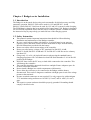
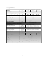
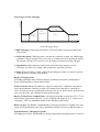
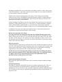
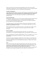
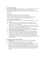
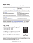
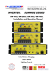
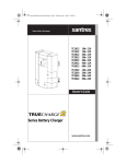
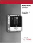
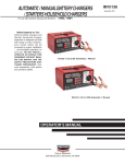
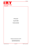
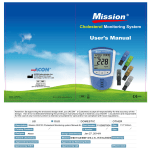
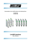
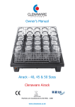
Power Master
Budget SERIES
SOLAR CHARGE CONTROLLER
6Amp/10Amp/20Amp/30Amp
Installation and Operation Manual
USER MANUAL
Solar Battery Charging
VER.B/980729
CONTENTS
Chapter 1 Budget series Installation ................................................................................. 3
1.1
Introduction....................................................................................................... 3
1.2
Safety Instruction.............................................................................................. 3
1.3
Specifications ..................................................................................................... 4
1.4
Mounting Dimension ........................................................................................ 5
1.5
Installation Overview........................................................................................ 6
Chapter 2 Budget series Operation.................................................................................... 8
2.1
Installation Steps ............................................................................................... 8
2.2
Adjustability of Solar Battery Charging......................................................... 9
2.3
Troubleshooting............................................................................................... 15
2
Chapter 1 Budget series Installation
1.1 Introduction
The Budget is an advanced design using a microcontroller for digital accuracy and fully
automatic operation. PM-SCC-6AB can be used for 12V and PM-SCC-10AB,
PM-SCC-20AB, PM-SCC-30AB can be used for 12V and 24V system for solar charging.
The PWM battery charging has been optimized for longer battery life. Budget is designed
for user-friendly operation. Please take the time to read this operator’s manual and follow
the instruction step by step to help you make full use of the charging system.
1.2 Safety Instruction
This manual contains important instructions that should be followed during
installation and maintenance of the Budget controller.
Be very careful when working with batteries. Lead acid batteries can generate
explosive gases, and short circuits can draw thousands of amps from the battery.
Read all instructions provided with the battery.
Do not exceed the rated current ratings of the controller.
Do not exceed a battery voltage of 24V (nominal) for PM-SCC-10AB,
PM-SCC-20AB, PM-SCC-30AB and 12V for PM-SCC-6AB. Do not use a battery
less than 12V.
Charge only 12, or 24 volt lead-acid batteries when using the standard battery
charging programs or NI-CAD batteries when DIP Switch number 2~4 is in the ON
position in the Budget.
DO NOT short circuit the PV array or load while connected to the controller. This
will damage the controller.
The controller should be protected from direct sunlight. Ensure adequate space for
air flow around the controller.
Do not install a Budget in a sealed compartment with batteries.
Never allow the solar array to be connected to the Budget with the battery
disconnected. This can be a dangerous condition with high open-circuit solar voltage
present at the terminals.
Pressure terminal connectors are not required. Use only copperwire with minimum
75°C insulation rating and between 10 AWG (5.2 mm2) and 14 AWG (2.1 mm2)
gage.
The negative system conductor should be properly grounded. Grounding should
comply with local codes.
3
1.3 Specifications
MODEL
ELECTRICAL
System voltage ratings
Current ratings-Battery Charge
Control
Accuracy
Min. voltage to operate
Max. solar array Voc
Max. operating voltage
Total current consumption
High temp shutdown
PM-SCC6AB
PM-SCC10AB
12 Vdc
6A
± 60 mV
6V
30 V
16 V
6 mA
N/A
PM-SCC20AB
PM-SCC30AB
12, 24 Vdc
10A
20A
30A
12/24V:≦0.1 % ± 50 mV
9V
50 V
34 V
9 mA
90ºC disconnect solar
70ºC reconnect solar
BATTERY CHARGING / Built-in BTS
Charge algorithm
PWM, constant voltage
–5mV/ºC /
12V:–5mV/ºC / cell (25ºC ref)
Temp comp. coefficient
cell
24V:–10mV/ºC / cell (25ºC ref)
(25ºC ref)
Temp comp. range
0ºC to +50ºC
PWM
Temp comp. setpoints
setpoint:
PWM, float, equalize (with BTS)
14.1V
MECHANICAL
Weight
0.2 Kgs
0.3 Kgs
0.4 Kgs
Power terminals
6A Rated
10A Rated
20A Rated
30A Rated
ENVIRONMENTAL
Ambient temperature
–40 to +45ºC
Storage temperature
–55 to +85ºC
Humidity
100% (NC)
Enclosure
Indoor & vented, (powder coated steel)
OPTIONS
Remote Panel
Optional LCD display for PM-SCC-30AB only
Specifications subject to change without notice
4
1.4 Mounting Dimension
Unit: mm
Length
Model
PM-SCC-6AB
PM-SCC-10AB
PM-SCC-20AB
PM-SCC-30AB
L
L1
106 mm
99 mm
168 mm
161 mm
236 mm
229 mm
5
1.5 Installation Overview
The installation is straight forward but it is important that each step is done correctly and
safely. A mistake can lead to dangerous voltage and current levels. Be sure to carefully
follow the following instructions for all the terminal connection.
Charge
Status
LED
DIP
Switches
PV+
Battery
Pos +
PV–
Restart/stop
Equalization
Battery
Neg–
BTS
Remote
Panel
Control Terminal Connection
Name
Description
PV+
Connecting terminal for Solar Array Positive
PV–
Connecting terminal for Solar Array Negative
Battery +
Connecting terminal for Battery cable Positive
Battery–
Connecting terminal for Battery cable Negative
ON Selection of battery voltage for 12V system
DIP Switch 1
OFF Selection of battery voltage for 24V system
DIP Switch 2,3, 4
Battery charge control mode: Battery charging algorithm
ON Selection of Auto Equalization
OFF Selection of Manual Equalization
There is no DIP switches for PM-SCC-6AB model.
Connecting port for the optional LCD remote panel for PM-SCC-30AB
Remote Panel
model
BTS
Battery Temperature Sensor is built-in Budget for temperature compensation
LED Status Indicators
DIP Switch 5
6
Charge Status LED
Push Buttons
PUSH
Restart/Stop
Equalization
HOLD
Restart/Stop
Equalization
Blinking Green: Charging is in the state of Bulk or Absorption
Solid Green: Charging is in the state of Float
Solid Orange: Charging in the state of Equalization
Solid Red: Charging in the state of fault: Over Current
Blinking Red: Charging in the state of fault: Over Temp.
When there is a fault occurring, push Restart/Stop Equalization to reset it.
When DIP Switch 5 is set at OFF, hold Restart/Stop Equalization to manually
start equalization and press it again to stop equalization.
※ Optional Remote LCD Meter for PM-SCC-30AB
One Remote LCD Meter can be added to the PM-SCC-30AB at any time during or
after installation. The display is a 2x16 LCD meter with backlighting. One
pushbutton is used to scroll through the displays function.
There are a series of display screens that provide information such as:
• Operating information and data
• Reset Amp-Hours
7
Chapter 2 Budget series Operation
2.1 Installation Steps
This section provides a brief overview of how to get started using the Budget controller.
However, please review the entire manual to ensure best performance and years of
trouble-free service.
NOTES:
The Budget prevents reverse current leakage at night, so a blocking diode is not
required in the system.
The connector terminals will accept a maximum wire size of AWG #10 (up to 5.2
mm2). A flathead screwdriver is required. (Some #10 spade connectors may not fit in
this terminal.)
Tighten each terminal clamping screw to 20 inch-pounds of torque.
The Budget is designed to regulate power from a PV array. Other generators can be
connected directly to the battery, however, with no effect on the Budget.
STEPS:
1. Mount the Budget on to a vertical surface. Allow a minimum of 5 cm (2 inches) space
above and below the controller for air flow.
2. Make sure the PV currents will not exceed the ratings of the Budget model being
installed.
3. The connections to the Budget terminals are shown in the panel drawing.
4. Connect the BATTERY first. Be careful that bare wires do not touch the metal case of
the controller.
※ The BATTERY must be connected before the SOLAR to properly start the
microcontroller.
※ A battery below 10 volts may not start the microcontroller properly. Make sure the
battery is charged before installing the system.
5. Connect the SOLAR (PV array) next. The green LED indicator will light if the array is
connected during the daytime and the array is wired correctly.
※ Remember that the Solar array will generate power whenever in sunlight. Also, be
8
careful not to shortcircuit the PV array while connected to the controller, since this
will damage the controller.
6. Set the DIP Switch 1 for the voltage system, set the DIP Switch 2, 3, 4 for battery
charging algorithm.
7. For most effective surge protection, it is recommended that the negative system
conductor be properly grounded.
Solar Battery Charging
The energy output of a solar array is used for recharging the system battery.
The Budget manages the charging process to be efficient and to maximize the life of the
battery. Charging includes a bulk charging stage, PWM absorption, float and equalization
for PM-SCC-10AB, PM-SCC-20AB and PM-SCC-30AB.
2.2 Adjustability of Solar Battery Charging
Five DIP Switches permit the following parameters to be adjusted at the installation site:
DIP Switch
Solar battery charging
1
ON
OFF
Select Battery Voltage
12V system
24V system
2~4
Standard battery charging programs
5
ON
OFF
Select Auto/Manual Equalization
Auto Equalization
Manual Equalization
PWM Battery Charging
PWM (Pulse Width Modulation) battery charging is the most efficient and effective
method for recharging a battery in a solar system.
Selecting the best method for charging your battery together with a good maintenance
program will ensure a healthy battery and long service life. Although the Budget’s battery
charging is fully automatic, the following information is important for getting the best
performance from your Budget controller and battery.
9
VOLTAGE
Four Stages of Solar Charging
3
EQUALIZE
NIGHT
1
BULK
CHARGING
2
PWM
ABSORPTION
4
FLOAT
NIGHT
TIME
Solar Charging Stages
1. Bulk Charging: In this stage, the battery will accept all the current provided by the
solar system.
2. PWM Absorption: When the battery reaches the regulation voltage, the PWM begins
to hold the voltage constant. This is to avoid over-heating and over-gassing the battery.
The current will taper off to safe levels as the battery becomes more fully charged.
3. Equalization: Many batteries benefit from a periodic boost charge to stir the
electrolyte, level the cell voltages, and complete the chemical reactions.
4. Float: When the battery is fully recharged, the charging voltage is reduced to prevent
further heating or gassing of the battery.
Battery Charging Notes
The Budget manages many different charging conditions and system configurations.
Some useful functions to know follow below.
Solar Overload: Enhanced radiation or “edge of cloud effect” conditions can generate
more current than the controller’s rating. The Budget will reduce this overload up to
130% of rated current by regulating the current to safe levels. If the current from the solar
array exceeds 150%, the controller will interrupt charging.
Battery Temperature Compensation: All charging setpoints are based on 25°C (77°F).
If the battery temperature varies by 5°C, the charging will change by 0.15 volts for a 12
volt battery. This is a substantial change in the charging of the battery.
Battery Types: The Budget’s standard battery charging programs are suitable for a wide
range of lead-acid battery types. These standard programs are select by DIP Switch 2~4.
Standard Battery Charging Programs
The Budget provides 8 standard battery charging algorithms (programs) that are selected
10
with the DIP Switches. These standard algorithms are suitable for lead-acid batteries
ranging from sealed (gel, AGM, maintenance free) to flooded to L-16 cells and Ni-cad
etc.
The table below summarizes the major parameters of the standard charging algorithms.
Note that all the voltages are for 12V systems (24V = 2X).
All values are 25ºC (77ºF).
A
B
DIP
Switches
Battery
Bulk
(2-3-4)
Type
Voltage
off-off-off 1 – Sealed
14.0
off-off-on 2 – Sealed
14.1
off-on-off 3 - Sealed
14.3
off-on-on 4 - Flooded
14.4
on-off-off 5 - Flooded
14.6
on-off-on 6 - Flooded
14.8
on-on-off 7 - L-16
15.0
on-on-on
8-NiCad
16.0
Standard Battery Charging Programs
C
D
Float
Voltage
13.4
13.4
13.4
13.4
13.4
13.4
13.4
14.5
Equalize
Voltage
None
14.2
14.4
15.1
15.3
15.3
15.3
None
E
Equalize
Time
(hours)
1
2
3
3
3
3
-
F
Equalize
Interval
(days)
28
28
28
28
28
14
-
A. Battery Type– These are generic lead-acid and Ni-cad battery types.
B. BULK Voltage–This is the PWM Absorption stage with constant voltage charging.
The “PWM voltage” is the maximum battery voltage that will be held constant. As the
battery becomes more charged, the charging current tapers off until the battery is fully
charged.
C. Float Voltage–When the battery is fully charged, the charging voltage will be reduced
to 13.4 volts for all battery types.
D. Equalization Voltage–During an equalization cycle, the charging voltage will be held
constant at this voltage.
E. Equalization Time–The charging at the selected equalization voltage will continue
for this number of hours. This may take more than one day to complete.
F. Equalization Interval–Equalizations are typically done once a month. Most of the
cycles are 28 days so the equalization will begin on the same day of the month. It can
be set by DIP Switch 2~4 for different interval days. Each new cycle will be reset as
the equalization starts so that a setting day period will be maintained.
Temperature Effects
Battery Temperature Sensor (BTS)
A sensor next to the remote panel is used for temperature compensated battery charging.
11
As the battery gets warmer, the gassing increases. As the battery gets colder, it becomes
more resistant to charging. Depending on how much the battery temperature varies, it
may be important to adjust the charging for temperature changes.
There are three battery charging parameters that are affected by temperature:
PWM Absorption
This is the most important part of charging that is affected by temperature because the
charging may go into PWM absorption almost every day. If the battery temperature is
colder, the charging will begin to regulate too soon and the battery may not be recharged
with a limited solar resource. If the battery temperature rises, the battery may heat and
gas too much.
Equalization
A colder battery will lose part of the benefit of the equalization. A warmer battery may
heat and gas too much.
Float
Float is less affected by temperature changes, but it may also undercharge or gas too
much depending on how much the temperature changes.
The BTS corrects the three charging setpoints noted above by the following values:
• 12 volt battery: –0.030 volts per °C (–0.017 volts per °F)
• 24 volt battery: –0.060 volts per °C (–0.033 volts per °F)
Variations in battery temperature can affect charging, battery capacity, and battery life.
The greater the range of battery temperatures, the greater the impact on the battery. For
example, if the temperature falls to 10°C (50°F) this 15°C (27°F) change in temperature
will change the PWM, equalization and float setpoints by 0.90V in a 24V system.
Temperature
12 Volt
24 Volt
50ºC / 122ºF
– 0.75 V
–1.50 V
45ºC / 113ºF
– 0.60 V
– 1.20 V
40ºC / 104ºF
– 0.45 V
– 0.90 V
35ºC / 95ºF
– 0.30 V
– 0.60 V
30ºC / 86ºF
– 0.15 V
– 0.30 V
25ºC / 77ºF
0V
0V
20ºC / 68ºF
+ 0.15 V
+ 0.30 V
15ºC / 59ºF
+ 0.30 V
+ 0.60 V
10ºC / 50ºF
+ 0.45 V
+ 0.90 V
5ºC / 41ºF
+ 0.60 V
+ 1.20 V
0ºC / 32ºF
+ 0.75 V
+ 1.50 V
Temperature Compensation
Equalization
Routine equalization cycles are often vital to the performance and life of a battery —
particularly in a solar system. During battery discharge, sulfuric acid is consumed and
soft lead sulfate crystals form on the plates. If the battery remains in a partially
12
discharged condition, the soft crystals will turn into hard crystals over time. This process,
called “lead sulfation,” causes the crystals to become harder over time and more difficult
to convert back to soft active materials.
Sulfation from chronic undercharging of the battery is the leading cause of battery
failures in solar systems. In addition to reducing the battery capacity, sulfate build-up is
the most common cause of buckling plates and cracked grids. Deep cycle batteries are
particularly susceptible to lead sulfation.
Normal charging of the battery can convert the sulfate back to the soft active material if
the battery is fully recharged. However, a solar battery is seldom completely recharged,
so the soft lead sulfate crystals harden over a period of time. Only a long controlled
overcharge, or equalization, at a higher voltage can reverse the hardening sulfate crystals.
In addition to slowing or preventing lead sulfation, there are also other benefits from
equalizations of the solar system battery. These include:
Balance the individual cell voltages.
Over time, individual cell voltages can drift apart due to slight differences in the cells.
For example, in a 12 cell (24V) battery, one cell is less efficient in recharging to a final
battery voltage of 28.8 volts (2.4 V/c). Over time, that cell only reaches 1.85 volts, while
the other 11 cells charge to 2.45 volts per cell. The overall battery voltage is 28.8V, but
the individual cells are higher or lower due to cell drift. Equalization cycles help to bring
all the cells to the same voltage.
Mix the electrolyte.
In flooded batteries, especially tall cells, the heavier acid will fall to the bottom of the cell
over time. This stratification of the electrolyte causes loss of capacity and corrosion of the
lower portion of the plates. Gassing of the electrolyte from a controlled overcharging
(equalization) will stir and remix the acid into the battery electrolyte.
NOTE: Excessive overcharging and gassing too vigorously can damage the battery
plates and cause shedding of active material from the plates. An equalization that is
too high or for too long can be damaging. Review the requirements for the
particular battery being used in your system.
Standard Equalization Programs
Both automatic and manual equalizations can be performed using the standard charging
programs.
Manual Equalization
The Budget is shipped with the DIP Switch set for manual equalization only. This is to
avoid an unexpected or unwanted automatic equalization. In the manual mode, the
pushbutton is used to both start or stop a manual equalization. Hold the pushbutton down
for 5 seconds to start or stop an equalization (depending on whether an equalization is in
progress or not).
13
There are no limits to how many times the pushbutton can be used to start and stop
equalizations. Equalizations will be terminated automatically as per the charging program
selected if the pushbutton is not used to manually stop the equalization.
Automatic Equalization
If the equalization DIP Switch 5 is moved to the ON position, the equalizations will begin
automatically as per the charging program selected. Other than starting, the automatic and
manual equalizations are the same and follow the standard charging program selected.
The pushbutton can be used to start and stop equalizations in both the manual and
automatic mode.
Typical Equalizations
The automatic equalizations will occur at the selected charging program from DIP Switch
2~4. When an equalization begins (auto or manual), the battery charging voltage
increases up to the equalization voltage (Veq). The battery will remain at Veq for the
time specified in the selected charging program.
The equalization process will continue until the voltage has been held above the bulk
setting for a cumulate period of two hours. A second manual equalization cycle can be
started with the pushbutton if needed.
If the equalization cannot be completed in one day, it will continue the next day or days
until finished. After an equalization is completed, charging will return to PWM
absorption.
When to Equalize
The ideal frequency of equalizations depends on the battery type (leadcalcium,
lead-antimony, etc.), the depth of discharging, battery age, temperature, and other factors.
One very broad guide is to equalize flooded batteries every 1 to 3 months or every 5 to 10
deep discharges. Some batteries, such as the L-16 group, will need more frequent
equalizations.
The difference between the highest cell and lowest cell in a battery can also indicate the
need for an equalization. Either the specific gravity or the cell voltage can be measured.
The battery manufacturer can recommend the specific gravity or voltage values for your
particular battery.
Float
When a battery becomes fully charged, dropping down to the float stage will provide a
very low rate of maintenance charging while reducing the heating and gassing of a fully
charged battery. When the battery is fully recharged, there can be no more chemical
reactions and all the charging current is turned into heat and gassing.
The purpose of float is to protect the battery from long-term overcharge. From the PWM
absorption stage, charging is dropped to the float voltage. This is typically 13.4V.
14
2.3 Troubleshooting
The Budget is very rugged and designed for the most extreme operating conditions. Most
PV system problems will be caused by connections, voltage drops, and loads.
Troubleshooting the Budget controller is simple. Some basic troubleshooting procedures
are listed below.
CAUTIONS:
1. Troubleshooting should be done by qualified personnel only.
2. Remember that a battery can cause serious damage if shorted.
3. There are no user serviceable parts, fuses or circuit breakers inside the Budget.
4. Observe all normal precautions when working with energized circuitry.
1. BATTERY IS NOT CHARGING
Check the green LED indicator. The green CHARGING LED should be on if it is
daytime.
Check that the proper battery charging has been selected by DIP Switches.
Check that all wire connections in the system are correct and tight. Check the
polarity (+ and –) of the connections.
Measure the PV array open-circuit voltage and confirm it is within normal limits. If
the voltage is low or zero, check the connections at the PV array itself. Disconnect
the PV from the controller when working on the PV array.
Check that the load is not drawing more energy than the PV array can provide.
Check if there are excessive voltage drops between the controller and the battery.
This will cause undercharging of the battery.
Check the condition of the battery. Determine if the battery voltage declines at
night with no load. If unable to maintain its voltage, the battery may be failing.
Measure the PV voltage and the battery voltage at the Budget terminals. If the
voltage at the terminals is the same (within a few tenths of volts) the PV array is
charging the battery. If the PV voltage is close to the open circuit voltage of the
panels and the battery voltage is low, the controller is not charging the batteries and
may be damaged.
2. BATTERY VOLTAGE IS TOO HIGH
First check the operating conditions to confirm that the voltage is higher than
specifications.
Check that the proper battery charging has been selected by DIP Switches.
Check that all wire connections in the system are correct and tight.
Disconnect the PV array and momentarily disconnect the lead from the BATTERY
positive terminal. Reconnect the battery terminal and leave the PV array
disconnected. The Green charging light should not be lit. Measure the voltage at the
SOLAR terminals (with the array still disconnected). If the Green charging light is
on or battery voltage is measured at the SOLAR terminals, the controller may be
damaged.
15