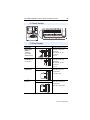
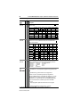
1
Installation Instructions
PowerFlex® 70 Adjustable Frequency
AC Drive
When reading this document, look for this symbol “ Step x ” to guide
you through the 5 BASIC STEPS needed to install and perform a Basic
Start-Up of the PowerFlex 70. A Human Interface Module (HIM) is
required to perform the Basic Start-Up routine covered in this manual.
The information provided Does Not replace the User Manual and is
intended for qualified drive service personnel only.
For detailed PowerFlex 70 information including advanced start-up
routines, programming, application considerations and related
precautions refer to the following publications online at
www.rockwellautomation.com/literature:
Title
PowerFlex 70 User Manual
DriveGuard Safe-Off Option (Series B) for PowerFlex 40P and
PowerFlex 70 AC Drives
PowerFlex Comm Adapter Manuals
Dynamic Braking Resistor Calculator
PowerFlex 70 and 700 Reference Manual - Volume 1
PowerFlex Reference Manual
Wiring and Grounding Guidelines for Pulse Width Modulated (PWM)
AC Drives
Publication
20A-UM001
20A-UM003
20COMM-UM
PFLEX-AT001
PFLEX-RM001
PFLEX-RM004
DRIVES-IN001
To order paper copies of technical documentation, contact your local
Rockwell Automation distributor or sales representative.
To find your local Rockwell Automation distributor, visit
www.rockwellautomation.com/locations
Allen-Bradley Drives Technical Support
Online at…
By Email at…
By Telephone at…
www.ab.com/support/abdrives [email protected] 262-512-8176
2
PowerFlex® 70 Adjustable Frequency AC Drive Installation Instructions
Installation Instructions in Other Languages
English
Deutsch
Français
Italiano
Español
Português
Dutch
This instruction sheet is available in multiple languages at
http://rockwellautomation.com/literature.
Select publication language and type “20A-IN009” in the search field.
Dieses Instruktionsblatt kann in mehreren Sprachen unter
http://rockwellautomation.com/literature gelesen werden.
Bitte Ihre Sprache anwählen und “20A-IN009” im Suchfeld eintippen.
Ces instructions sont disponibles dans différentes langues à l’adresse suivante:
http://rockwellautomation.com/literature.
Sélectionner la langue puis taper << 20A-IN009 >> dans le champ de recherche.
La presente scheda d’istruzione è disponibile in varie lingue sul sito
http://rockwellautomation.com/literature.
Selezionare la lingua desiderata e digitare “20A-IN009” nel campo di ricerca.
Puede encontrar esta hoja de instrucciones en varios idiomas en
http://rockwellautomation.com/literature.
Seleccione el idioma de publicación y escriba “20A-IN009” en el campo de búsqueda.
Esta folha de instruções está disponível em várias línguas em
http://rockwellautomation.com/literature.
Seleccione a língua de publicação e entre com “20A-IN009” no espaço de busca.
Dit instructieblad is beschikbaar in diverse talen op:
http://rockwellautomation.com/literature.
Kies taal van publicatie en tik “20A-IN009” in het zoekveld.
Chinese
从以下网页可以获得本说明书的多种语言的版本 :
(simplified) http://rockwellautomation.com/literature 。
请选择出版物的语言 , 并在搜索栏输入 “20A-IN009 印ٛ
Publication 20A-IN009C-EN-P
PowerFlex® 70 Adjustable Frequency AC Drive Installation Instructions
3
Table of Contents
Catalog Number Explanation . . . . . . . . . . . . . . . . . . . . .4
Step 1
Read the General Precautions . . . . . . . . . . . . . . . . . . . .4
Qualified Personnel. . . . . . . . . . . . . . . . . . . . . . . . . . . . . . . . .4
Personal Safety . . . . . . . . . . . . . . . . . . . . . . . . . . . . . . . . . . . .5
Product Safety. . . . . . . . . . . . . . . . . . . . . . . . . . . . . . . . . . . . .5
EMC Instructions . . . . . . . . . . . . . . . . . . . . . . . . . . . . . . . .7
CE Conformity . . . . . . . . . . . . . . . . . . . . . . . . . . . . . . . . . . . .7
Low Voltage Directive (2006/95/EC) . . . . . . . . . . . . . . . . . . .7
EMC Directive (89/336/EEC). . . . . . . . . . . . . . . . . . . . . . . . .7
General Notes . . . . . . . . . . . . . . . . . . . . . . . . . . . . . . . . . . . . .7
Essential Requirements for CE Compliance. . . . . . . . . . . . . .8
Step 2
Mount the Drive – Minimum Requirements . . . . . . . .9
Minimum Mounting Clearances . . . . . . . . . . . . . . . . . . . . . . .9
Maximum Surrounding Air Temperature . . . . . . . . . . . . . . . .9
Dimensions . . . . . . . . . . . . . . . . . . . . . . . . . . . . . . . . . . . . . .10
Step 3
Wire the Drive – Wire Recommendations . . . . . . . . .11
Terminal Block Specifications . . . . . . . . . . . . . . . . . . . . . . .12
Power & Ground Wiring. . . . . . . . . . . . . . . . . . . . . . . . . . . .14
Drive, Fuse & Circuit Breaker Ratings. . . . . . . . . . . . . . . . .14
Disconnecting MOVs and Common Mode Capacitors. . . . .21
Step 4
I/O Wiring . . . . . . . . . . . . . . . . . . . . . . . . . . . . . . . . . . . . . .27
I/O Terminal Positions . . . . . . . . . . . . . . . . . . . . . . . . . . . . .29
I/O Wiring Examples . . . . . . . . . . . . . . . . . . . . . . . . . . . . . .29
Hardware Enable Circuitry (Enhanced Control Only) . . . . .31
Safe Off Board Option (Enhanced Control Only) . . . . . . . .32
Encoder Interface Option (Enhanced Control Only) . . . . . .33
Step 5
Start-Up Check List . . . . . . . . . . . . . . . . . . . . . . . . . . . . .34
Prepare For Drive Start-Up . . . . . . . . . . . . . . . . . . . . . . . . . .34
Information About Start-Up Motor Tests . . . . . . . . . . . . . . .35
Appendix
First Powerup Menu Structure . . . . . . . . . . . . . . . . . . . . . . .36
Human Interface Module (HIM) Overview . . . . . . . . . . . . .37
Drive Status Indicators . . . . . . . . . . . . . . . . . . . . . . . . . . . . .41
Common I/O Programming Changes . . . . . . . . . . . . . . . . . .42
Troubleshooting – Abbreviated Fault & Alarm Listing . . . .43
Common Symptoms and Corrective Actions . . . . . . . . . . . .45
Manually Clearing Faults . . . . . . . . . . . . . . . . . . . . . . . . . . .47
Parameter List . . . . . . . . . . . . . . . . . . . . . . . . . . . . . . . . . . . .48
Publication 20A-IN009C-EN-P
4
PowerFlex® 70 Adjustable Frequency AC Drive Installation Instructions
Catalog Number Explanation
Position Number
1-3
4
5-7
8
9
10
11
12
13
14
15
16
20A
B
2P2
A
3
A
Y
Y
N
N
C
0
a
b
c
d
e
f
g
h
i
j
k
l
a
e
Drive
i
HIM
Emission Class
Code
Type
Code
20A
PowerFlex 70
0
Blank Cover
3
Full Numeric LCD
b
Voltage Rating
Code
Voltage
5
Prog. Only LCD
8
Wireless Interface Module IP66, NEMA/UL Type 4X/12
Only
Ph.
B
240V ac
3
C
400V ac
3
D
480V ac
3
E
600V ac
3
c
Interface Module
f
Documentation
Code
A
Manual
N
No Manual
g
kW (Hp)
2P2
2.2
0.37 (0.5)
022
22
5.5 (7.5)
Brake IGBT
Code
w/Brake IGBT
Y
Yes
d
h
Enclosure
Code
Enclosure
A
Panel Mount - IP 20, NEMA/UL
Type 1
C
F
Wall/Machine Mount = IP66,
NEMA/UL Type 4X/12 for
indoor use only
Wall/Machine Mount - IP54,
NEMA/UL Type 12
L
Flange Mount with Conformal
Coat
M
Panel Mount with Conformal
Coat
w/Resistor
Y
Yes
N
No
Only available on Frame E.
Step 1
N
Not Filtered
A & B Frames (Optional)
C, D, & E Frames
600V Frames A through D available only
without filter (Cat. Code N). 600V Frame E
available only with filter (Cat. Code A).
Increases size to Frame B.
j
Comm Slot
Version
B
BACnet
C
ControlNet (Coax)
D
DeviceNet
E
EtherNet/IP
R
RIO
S
RS485 DF1
N
None
Internal Brake Resistor
Code
Flange Mount - Front Chassis =
IP 20, NEMA/UL Type 1; Rear
Heatsink = IP66, NEMA/UL
Type 4X/12 for indoor/outdoor
use
G
Filtered
A & B Frames (Optional)
C, D, & E Frames (Standard)
Code
Examples:
Amps
Rating
A
Type
ND Output Rating for Voltage Rating
Code
Code
k
Control & I/O
Code
Control
Safe-Off
N
Standard
N/A
C
Enhanced
No
G
Enhanced
Yes
Not available as factory installed option for
600V ratings.
l
Feedback
Code
Feedback
N
NA - Standard Control
0
No Feedback - Enhanced
Control
1
5V/12V Encoder w/Enhanced
Control
Read the General Precautions
Qualified Personnel
!
ATTENTION: Only qualified personnel familiar with adjustable
frequency AC drives and associated machinery should plan or
implement the installation, start-up and subsequent maintenance of the
system. Failure to comply may result in personal injury and/or
equipment damage.
Publication 20A-IN009C-EN-P
PowerFlex® 70 Adjustable Frequency AC Drive Installation Instructions
5
Personal Safety
!
!
!
ATTENTION: To avoid an electric shock hazard, verify that the
voltage on the bus capacitors has discharged before performing any
work on the drive. Measure the DC bus voltage at the +DC terminal of
the Power Terminal Block and the -DC test point (refer to page 13 for
location). The voltage must be zero.
ATTENTION: Risk of injury or equipment damage exists. DPI or
SCANport host products must not be directly connected together via
1202 cables. Unpredictable behavior can result if two or more devices
are connected in this manner.
ATTENTION: The drive start/stop/enable control circuitry includes
solid state components. If hazards due to accidental contact with
moving machinery or unintentional flow of liquid, gas or solids exist,
an additional hardwired stop circuit may be required to remove the AC
line to the drive. An auxiliary braking method may be required.
Product Safety
!
!
!
!
ATTENTION: An incorrectly applied or installed drive can result in
component damage or a reduction in product life. Wiring or application
errors, such as, undersizing the motor, incorrect or inadequate AC
supply, or excessive ambient temperatures may result in malfunction of
the system.
ATTENTION: This drive contains ESD (Electrostatic Discharge)
sensitive parts and assemblies. Static control precautions are required
when installing, testing, servicing or repairing this assembly.
Component damage may result if ESD control procedures are not
followed. If you are not familiar with static control procedures,
reference Guarding Against Electrostatic Damage, publication
8000-4.5.2 or any other applicable ESD protection handbook.
ATTENTION: Configuring an analog input for 0-20 mA operation
and driving it from a voltage source could cause component damage.
Verify proper configuration prior to applying input signals.
ATTENTION: A contactor or other device that routinely disconnects
and reapplies the AC line to the drive to start and stop the motor can
cause drive hardware damage. The drive is designed to use control input
signals that will start and stop the motor. If an input device is used,
operation must not exceed one cycle per minute or drive damage will
occur.
Publication 20A-IN009C-EN-P
6
PowerFlex® 70 Adjustable Frequency AC Drive Installation Instructions
!
ATTENTION: The “adjust freq” portion of the bus regulator function
is extremely useful for preventing nuisance overvoltage faults resulting
from aggressive decelerations, overhauling loads, and eccentric loads. It
forces the output frequency to be greater than commanded frequency
while the drive’s bus voltage is increasing towards levels that would
otherwise cause a fault; however, it can also cause either of the
following two conditions to occur.
1. Fast positive changes in input voltage (more than a 10% increase
within 6 minutes) can cause uncommanded positive speed changes;
however an “OverSpeed Limit” fault will occur if the speed reaches
[Max Speed] + [Overspeed Limit]. If this condition is unacceptable,
action should be taken to 1) limit supply voltages within the
specification of the drive and, 2) limit fast positive input voltage
changes to less than 10%. Without taking such actions, if this operation
is unacceptable, the “adjust freq” portion of the bus regulator function
must be disabled (see parameters 161 and 162).
2. Actual deceleration times can be longer than commanded
deceleration times; however, a “Decel Inhibit” fault is generated if the
drive stops decelerating altogether. If this condition is unacceptable, the
“adjust freq” portion of the bus regulator must be disabled (see
parameters 161 and 162). In addition, installing a properly sized
dynamic brake resistor will provide equal or better performance in most
cases.
Note: These faults are not instantaneous and have shown test results
that take between 2 and 12 seconds to occur.
Output Contactor Precaution
!
ATTENTION: To guard against drive damage when using output
contactors, the following information must be read and understood.
One or more output contactors may be installed between the drive and
motor(s) for the purpose of disconnecting or isolating certain motors/
loads. If a contactor is opened while the drive is operating, power will
be removed from the respective motor, but the drive will continue to
produce voltage at the output terminals. In addition, reconnecting a
motor to an active drive (by closing the contactor) could produce
excessive current that may cause the drive to fault. If any of these
conditions are determined to be undesirable or unsafe, an auxiliary
contact on the output contactor should be wired to a drive digital input
that is programmed as “Enable.” This will cause the drive to execute a
coast-to-stop (cease output) whenever an output contactor is opened.
Publication 20A-IN009C-EN-P
PowerFlex® 70 Adjustable Frequency AC Drive Installation Instructions
7
EMC Instructions
CE Conformity(1)
Conformity with the Low Voltage (LV) Directive and Electromagnetic
Compatibility (EMC) Directive has been demonstrated using
harmonized European Norm (EN) standards published in the Official
Journal of the European Communities. PowerFlex Drives comply with
the EN standards listed below when installed according to the User and
Reference Manuals.
CE Declarations of Conformity are available online at:
www.ab.com/certification/ce/docs
Low Voltage Directive (2006/95/EC)
•
EN50178 Electronic equipment for use in power installations.
EMC Directive (89/336/EEC)
•
EN61800-3 Adjustable speed electrical power drive systems Part 3:
EMC product standard including specific test methods.
General Notes
•
Some drives are equipped with an adhesive label on the top of the
drive. If the adhesive label is removed from the top of the drive, the
drive must be installed in an enclosure with side openings less than
12.5 mm (0.5 in) and top openings less than 1.0 mm (0.04 in) to
maintain compliance with the LV Directive.
•
The motor cable should be kept as short as possible in order to avoid
electromagnetic emission as well as capacitive currents.
•
Use of line filters in ungrounded systems is not recommended.
•
PowerFlex drives may cause radio interference if used in a
residential or domestic environment. The installer is required to take
measures to prevent interference, in addition to the essential
requirements for CE compliance listed below, if necessary.
•
Conformity of the drive with CE EMC requirements does not
guarantee an entire machine or installation complies with CE EMC
requirements. Many factors can influence total machine/installation
compliance.
•
PowerFlex drives can generate conducted low frequency
disturbances (harmonic emissions) on the AC supply system. More
information regarding harmonic emissions can be found in the
PowerFlex Reference Manual, publication PFLEX-RM004.
(1) CE Certification testing has not been completed for 600 Volt class drives.
Publication 20A-IN009C-EN-P
8
PowerFlex® 70 Adjustable Frequency AC Drive Installation Instructions
Essential Requirements for CE Compliance
Conditions 1…6 listed below must be satisfied for PowerFlex drives to
meet the requirements of EN61800-3.
1. Standard PowerFlex 70 CE compatible Drive.
2. Review important precautions/attention statements throughout this
manual before installing drive.
3. Grounding as described in Chapter 1 of the User Manual, publication
20A-UM001.
4. Output power, control (I/O) and signal wiring must be braided,
shielded cable with a coverage of 75% or better, metal conduit or
equivalent attenuation.
5. All shielded cables should terminate with the proper shielded
connector.
6. Conditions in Table A.
Frame(s)
Table A
A
B
C,
D,
E
(1)
PowerFlex 70 EN61800-3 EMC Compatibility
Second Environment
Restrict Motor Internal
First Environment
Cable to
Filter
External Input
Restricted
Drive Description
40 m (131 ft)
Option Filter
Ferrite (1) Distribution
Drive Only
✔
✔
with any Comm Option
✔
✔
with Remote I/O
✔
✔
✔
Drive Only
✔
✔
See PowerFlex
with any Comm Option
✔
✔
Reference Manual
with Remote I/O
✔
✔
✔
Drive Only
✔
with any Comm Option
✔
with Remote I/O
✔
✔
Input cables through a Ferrite Core (Frames A, B and C Fair-Rite #2643102002 or equivalent,
Frames D and E Fair-Rite #2643251002 or equivalent).
Publication 20A-IN009C-EN-P
PowerFlex® 70 Adjustable Frequency AC Drive Installation Instructions
Step 2
9
Mount the Drive – Minimum Requirements
Minimum Mounting Clearances
Specified vertical clearance requirements are
intended to be from drive to drive. Other objects
can occupy this space; however, airflow must not
be reduced and inlet air temperature must not
exceed the product specification.
76.2 mm
(3.0 in)
76.2 mm
(3.0 in)
Maximum Surrounding Air Temperature
Enclosure Rating
Open Type, IP 20, NEMA/UL Type 1 & Flange Mount
IP54, IP 66 & NEMA/UL Type 4X/12
Temperature Range
0…50 °C (32…22 °F)
0…40 °C (32…104 °F)
Important: Some drives are equipped with an adhesive label on the top
of the chassis. Removing the adhesive label from the drive
changes the NEMA/UL enclosure rating from Type 1
Enclosed to Open Type.
Publication 20A-IN009C-EN-P
10
PowerFlex® 70 Adjustable Frequency AC Drive Installation Instructions
Dimensions
Table B
PowerFlex 70 Frames
Output Power
Frame Size
208…240V AC Input
400…480V AC Input
600V AC Input
kW
HP
Not (1) (2)
IP66
Not (1) (2)
IP66
Not (1) (2)
ND (HD)
ND (HD)
Filtered Filtered (4X/12) Filtered Filtered (4X/12) Filtered Filtered
0.37 (0.25) 0.5 (0.33) A
B
B
A
B
B
A
–
0.75 (0.55) 1 (0.75)
A
B
B
A
B
B
A
–
1.5 (1.1)
2 (1.5)
B
B
B
A
B
B
A
–
2.2 (1.5)
3 (2)
B
B
B
B
B
B
B
–
4 (3)
5 (3)
–
C
D
B
B
B
B
–
5.5 (4)
7.5 (5)
–
D
D
–
C
D
C
–
7.5 (5.5)
10 (7.5)
–
D
D
–
C
D
C
–
11 (7.5)
15 (10)
–
D
D
–
D
D
D
–
15 (11)
20 (15)
–
E
E
–
D
D
D
–
18.5 (15) 25 (20)
–
E
E
–
D
D
D
–
22 (18.5) 30 (25)
–
–
–
–
D
D
D
–
30 (22)
40 (30)
–
–
–
–
E
E
–
E
37 (30)
50 (40)
–
–
–
–
E
E
–
E
(1) Not Filtered indicated if Position 13 of the Catalog Number = N.
(2) Filtered indicated if Position 13 of the Catalog Number = A.
IP20/66 (NEMA/UL Type 1/4X/12)
A
D
E
IP66
(4X/12)
B
B
B
B
B
D
D
D
D
D
D
E
E
Flange Mount
C
A
C
B
B
D
F
Dimension Dimensions are in millimeters and (inches)
B
C
D
Frame A
IP20 / NEMA Type 1
A
122.4 (4.82) 225.7 (8.89) 179.8 (7.08) 94.2 (3.71)
B
171.7 (6.76) 234.6 (9.24) 179.8 (7.08) 122.7 (4.83)
C
185.0 (7.28) 300.0 (11.81) 179.8 (7.08) 137.6 (5.42)
D
219.9 (8.66) 350.0 (13.78) 179.8 (7.08) 169.0 (6.65)
E
280.3 (11.04) 555.8 (21.88) 207.1 (8.15) 200.0 (7.87)
IP66 / NEMA Type 4X/12
B
171.7 (6.76) 239.8 (9.44) 203.3 (8.00) 122.7 (4.83)
D
219.9 (8.66) 350.0 (13.78) 210.7 (8.29) 169.0 (6.65)
E
280.3 (11.04) 555.8 (21.88) 219.8 (8.65) 200.0 (7.87)
Flange Mount
A
156.0 (6.14) 225.8 (8.89) 178.6 (7.03) 123.0 (4.84)
B
205.2 (8.08) 234.6 (9.24) 178.6 (7.03) 123.0 (4.84)
C
219.0 (8.62) 300.0 (11.81) 178.6 (7.03) 123.0 (4.84)
D
248.4 (9.78) 350.0 (13.78) 178.6 (7.03) 123.0 (4.84)
E
280.3 (11.04) 555.8 (21.88) 207.1 (8.15) 117.2 (4.61)
(1) Weights include Human Interface Module (HIM).
Publication 20A-IN009C-EN-P
E
E
F
Weight (1)
kg (lb)
211.6 (8.33)
220.2 (8.67)
285.6 (11.25)
335.6 (13.21)
491.0 (19.33)
5.8 (0.23)
5.8 (0.23)
5.8 (0.23)
5.8 (0.23)
6.9 (0.27)
2.71 (6.0)
3.60 (7.9)
6.89 (15.2)
9.25 (20.4)
18.60 (41.0)
220.2 (8.67) 5.8 (0.23)
335.6 (13.21) 5.8 (0.23)
491.0 (19.33) 6.9 (0.27)
3.61 (8.0)
9.13 (20.1)
18.60 (41.0)
55.6 (2.19)
55.6 (2.19)
55.6 (2.19)
55.6 (2.19)
89.9 (3.54)
2.71 (6.0)
3.60 (7.9)
6.89 (15.2)
9.25 (20.4)
18.60 (41.0)
–
–
–
–
–
PowerFlex® 70 Adjustable Frequency AC Drive Installation Instructions
Step 3
Wire the Drive – Wire Recommendations
Type
Power
Wire Type(s)
Standard
(1)(2)
Signal
(1) (3) (4)
11
Min. Insulation
Rating
Description
• Four tinned copper
600V, 90 °C (194 °F)
conductors with XLPE
XHHW2/RHW-2
insulation.
Anixter
B209500-B209507, Belden • Copper braid/aluminum foil
combination shield and
29501-29507, or
tinned copper drain wire.
equivalent
• PVC jacket.
Standard Belden 8760/9460(or
Analog I/O equiv.)
Belden 8770(or equiv.)
0.750 mm2 (18AWG), twisted 300V,
pair, 100% shield with drain. 75…90 °C
(167…194 °F)
0.750 mm2 (18AWG), 3
cond., shielded for remote pot
only.
Multi-conductor shielded 0.750 mm2 (18AWG), 3
300V,
cable such as Belden
conductor, shielded.
60 °C (140 °F)
8770(or equiv.)
Control and signal wires should be separated from power wires by at least 0.3 meters (1 foot).
The use of shielded wire for AC input power may not be necessary but is always recommended.
If the wires are short and contained within a cabinet which has no sensitive circuits, the use of
shielded wire may not be necessary, but is always recommended.
I/O terminals labeled “(–)” or “Common” are not referenced to earth ground and are designed to
greatly reduce common mode interference. Grounding these terminals can cause signal noise.
Digital I/O Shielded
(1) (3) (4)
(1)
(2)
(3)
(4)
Input Power Conditioning
Certain events on the power system supplying a drive can cause
component damage or shortened product life. These conditions are
divided into 2 basic categories:
1. All drives
–
The power system has power factor correction capacitors
switched in and out of the system, either by the user or by the
power company.
–
The power source has intermittent voltage spikes in excess of
6000 volts. These spikes could be caused by other equipment on
the line or by events such as lightning strikes.
–
The power source has frequent interruptions.
2. 5 HP or Less Drives (in addition to “1” above)
–
The nearest supply transformer is larger than 100 kVA or the
available short circuit (fault) current is greater than 100,000 A.
–
The impedance in front of the drive is less than 0.5%.
Publication 20A-IN009C-EN-P
12
PowerFlex® 70 Adjustable Frequency AC Drive Installation Instructions
If any or all of these conditions exist, it is recommended that the user
install a minimum amount of impedance between the drive and the
source. This impedance could come from the supply transformer itself,
the cable between the transformer and drive or an additional transformer
or reactor. The impedance can be calculated using the information
supplied in the Wiring and Grounding Guidelines for Pulse Width
Modulated (PWM) AC Drives, publication DRIVES-IN001.
Single-Phase Input Power
The PowerFlex 70 drive is typically used with a three-phase input
supply. The drive has been listed by U.L. to operate on single-phase
input power. Single-phase operation provides 50% of the three-phase
rated current. Refer to Table F through Table H.
Generator Input Power
Contact Allen-Bradley Drives Technical Support for details on how to
properly power a drive using generator power.
Terminal Block Specifications
Name
Frame Description
Wire Size Range (1)
Torque
Maximum
Maximum
Minimum
Power Terminal A, B, C Input power and
4.0 mm2 0.3 mm2 1.1 N•m
Block
motor connections (10 AWG) (22 AWG) (10 lb•in)
I/O Terminal
Block
Recommended
0.8 N•m
(7 lb•in)
D
Input power and
10.0 mm2 0.8 mm2 1.7 N•m
motor connections (6 AWG) (18 AWG) (15 lb•in)
1.4 N•m
(12 lb•in)
E
Input power and
25.0 mm2 2.5 mm2 2.71 N•m
motor connections (3 AWG) (14 AWG) (24 lb•in)
2.71 N•m
(24 lb•in)
All
Signal & control
connections
1.5 mm2 0.05 mm2 0.55 N•m
(16 AWG) (30 AWG) (4.9 lb•in)
0.5 N•m
(4.4 lb•in)
SHLD Terminal All
Terminating point
for wiring shields
—
—
1.6 N•m
(14 lb•in)
1.6 N•m
(14 lb•in)
(1) Maximum/minimum sizes that the terminal block will accept - these are not recommendations.
Publication 20A-IN009C-EN-P
PowerFlex® 70 Adjustable Frequency AC Drive Installation Instructions
13
Figure 1 Frame A, B, C, D Power Terminal Block and DC Bus Test Points
➊
-DC
-DC
L1
R
L2
S
L3 BR1 BR2 T1
T +DC BRK U
T2
V
T3
W
PE
PE
Figure 2 Frame E Power Terminal Block
L1
R
L2
S
L3
T
Terminal
R
S
T
BR1
Description
R (L1)
S (L2)
T (L3)
DC Brake
BR2
DC Brake
U
V
W
PE
PE
U (T1)
V (T2)
W (T3)
PE Ground
PE Ground
-DC
DC Bus (–)
+DC
DC Bus (+)
+DC –DC BR1 BR2
T1
U
T2
V
T3
W
PE
PE
M6
M6
Notes
3-Phase AC Line Input Power
For 1-Phase Input, connect to any two terminals.
DB Resistor Connection - Important: Do not
connect both an internal and external DB resistor at
the same time. This may violate the minimum
allowed DB resistance and cause drive damage.
To Motor
To Motor
To Motor
➊ Test point on Frames A, B, C, and D located to
the left or right of the Power Terminal Block.
Frame E has a dedicated terminal.
Figure 3 Power Input Terminals on Frame B with Internal RFI Filter Option
-DC
-DC
L1
R
L2
S
L3
T
L1
R
L2
S
L3 BR1 BR2 T1
T +DC BRK U
T2
V
T3
W
PE
PE
Publication 20A-IN009C-EN-P
14
PowerFlex® 70 Adjustable Frequency AC Drive Installation Instructions
Power & Ground Wiring
R (L1)
S (L2)
T (L3)
U (T1)
V (T2)
W (T3)
PE
SHLD
Drive, Fuse & Circuit Breaker Ratings
The tables on the following pages provide drive ratings (including
continuous, 1 minute and 3 second) and recommended AC line input
fuse and circuit breaker information. Both types of short circuit
protection are acceptable for UL and IEC requirements. Sizes listed are
the recommended sizes based on 40 °C and the U.S. N.E.C. Other
country, state or local codes may require different ratings.
Fusing
If fuses are chosen as the desired protection method, refer to the
recommended types listed below. If available amp ratings do not match
the tables provided, the closest fuse rating that exceeds the drive rating
should be chosen.
• IEC – BS88 (British Standard) Parts 1 & 2 (1), EN60269-1, Parts 1 &
2, type gG or equivalent should be used.
• UL – UL Class CC, T, RK1 or J should be used.
Circuit Breakers
The “non-fuse” listings in the following tables include both circuit
breakers (inverse time or instantaneous trip) and 140M Self-Protecting
Motor Starters. If one of these is chosen as the desired protection
method, the following requirements apply.
•
IEC and UL – Both types of devices are acceptable for IEC and UL
installations.
(1) Typical designations include, but may not be limited to the following; Parts 1 & 2: AC,
AD, BC, BD, CD, DD, ED, EFS, EF, FF, FG, GF, GG, GH.
Publication 20A-IN009C-EN-P
A
A
B
B
C
D
D
D
E
E
0.5
1
2
3
5
7.5
10
15
20
25
20AB2P2
20AB4P2
20AB6P8
20AB9P6
20AB015
20AB022
20AB028
20AB042
20AB054
20AB070
A
A
B
B
C
D
D
D
E
E
0.5
1
2
3
5
7.5
10
15
20
25
240 Volt AC Input
20AB2P2
20AB4P2
20AB6P8
20AB9P6
20AB015
20AB022
20AB028
20AB042
20AB054
20AB070
0.33
0.75
1.5
2
3
5
7.5
10
15
20
0.33
0.75
1.5
2
3
5
7.5
10
15
20
HP
Rating
ND HD
208 Volt AC Input
Drive
Catalog
Number
2.5
4.8
8.7
12.2
13.9
19.9
25.7
38.7
49.8
64.5
2.9
5.6
10
14
16
23.3
29.8
39.8
57.5
72.3
1.1
2
3.6
5.1
5.8
8.3
10.7
16.1
20.7
26.8
1.1
2
3.6
5.1
5.8
8.3
10.7
14.3
20.7
26.0
2.2
4.2
6.8
9.6
15.3
22
28
42
54
70
2.5
4.8
7.8
11
17.5
25.3
32.2
43
62.1
78.2
2.4
4.8
9
10.6
17.4
24.4
33
46.2
63
81
2.7
5.5
10.3
12.1
19.2
27.8
37.9
55.5
72.4
93.1
3.3
6.4
12
14.4
23.2
33
44
63
84
108
3.7
7.4
13.8
16.5
26.6
37.9
50.6
74
96.6
124
3
6
15
20
20
25
35
50
60
90
6
10
15
20
20
30
40
60
80
90
4.5
9
15
20
30
45
60
90
100
150
6
10
15
25
35
50
70
100
125
175
3
6
15
20
20
25
35
50
60
90
6
10
15
20
20
30
40
60
80
90
8
15
25
35
60
80
110
150
200
275
10
17.5
30
40
70
100
125
175
200
300
15
15
25
35
60
80
110
150
200
275
15
15
30
40
70
100
125
175
200
300
3
7
15
15
30
30
50
50
100
100
7
7
15
30
30
30
50
70
100
100
140M-C2E-B25
140M-C2E-B63
140M-C2E-C10
140M-C2E-C16
140M-C2E-C16
140M-C2E-C25
–
–
–
–
140M-C2E-B40
140M-C2E-B63
140M-C2E-C10
140M-C2E-C16
140M-C2E-C20
140M-C2E-C25
–
–
–
–
140M-D8E-B25
140M-D8E-B63
140M-D8E-C10
140M-D8E-C16
140M-D8E-C16
140M-D8E-C25
–
–
–
–
140M-D8E-B40
140M-D8E-B63
140M-D8E-C10
140M-D8E-C16
140M-D8E-C20
140M-D8E-C25
–
–
–
–
–
–
140M-F8E-C10
140M-F8E-C16
140M-F8E-C16
140M-F8E-C25
140M-F8E-C32
140M-F8E-C45
–
–
–
–
140M-F8E-C10
140M-F8E-C16
140M-F8E-C20
140M-F8E-C25
140M-F8E-C32
140M-F8E-C45
–
–
–
–
–
–
–
140-CMN-2500
140-CMN-4000
140-CMN-6300
140-CMN-6300
140-CMN-9000
–
–
–
–
–
140-CMN-2500
140-CMN-4000
140-CMN-6300
140-CMN-6300
140-CMN-9000
Motor
Dual
Circuit
Input
Element Time Non-Time
Circuit
(4)
Protector (6) 140M Motor Protector with Adjustable Current Range (7) (8)
Ratings
Output Amps
Delay Fuse
Delay Fuse
Breaker
(2)
(3)
Amps kVA Cont. 1 Min. 3 Sec. Min. (2) Max. (3) Min.
Max.
Max.(5)
Max.(5)
Available Catalog Numbers (9)
208/240 Volt AC Three-Phase Input Drive Ratings and Input Protection Devices (See page 17 for Notes)
Frame(1)
Table C
PowerFlex® 70 Adjustable Frequency AC Drive Installation Instructions
15
Publication 20A-IN009C-EN-P
Publication 20A-IN009C-EN-P
A
A
A
B
B
C
C
D
D
D
D
E
E
0.37
0.75
1.5
2.2
4
5.5
7.5
11
15
18.5
22
30
37
20AD1P1
20AD2P1
20AD3P4
20AD5P0
20AD8P0
20AD011
20AD014
20AD022
20AD027
20AD034
20AD040
20AD052
20AD065
A
A
A
B
B
C
C
D
D
D
D
E
E
0.5
1
2
3
5
7.5
10
15
20
25
30
40
50
480 Volt AC Input
20AC1P3
20AC2P1
20AC3P5
20AC5P0
20AC8P7
20AC011
20AC015
20AC022
20AC030
20AC037
20AC043
20AC060
20AC072
0.33
0.75
1.5
2
3
5
7.5
10
15
20
25
30
40
0.25
0.55
1.1
1.5
3
4
5.5
7.5
11
15
18.5
22
30
1.3
2.4
3.8
5.6
9.8
9.4
12.4
19.9
24.8
31.2
36.7
47.7
59.6
1.6
2.5
4.3
6.5
11.3
10.5
145.1
21.9
30.3
35
40.7
56.8
68.9
1.1
2
3.2
4.7
8.4
7.9
10.4
16.6
20.6
25.9
30.5
39.7
49.6
1.1
1.8
3
4.5
7.8
7.6
10.4
15.2
21
24.3
28.2
39.3
47.8
1.1
2.1
3.4
5
8
11
14
22
27
34
40
52
65
1.3
2.1
3.5
5
8.7
11.5
15.4
22
30
37
43
60
72
1.2
2.4
4.5
5.5
8.8
12.1
16.5
24.2
33
40.5
51
60
78
1.4
2.4
4.5
5.5
9.9
13
17.2
24.2
33
45
56
66
90
1.6
3.2
6
7.5
12
16.5
22
33
44
54
68
80
104
1.9
3.2
6
7.5
13.2
17.4
23.1
33
45
60
74
90
120
kW (400V)
HP (480V) Input
Rating
Ratings
Output Amps
ND HD Amps kVA Cont. 1 Min. 3 Sec.
400 Volt AC Input
Drive
Catalog
Number
3
3
6
10
15
15
20
25
35
40
50
60
80
3
4
6
10
15
15
20
30
40
50
60
80
90
3
6
6
10
15
20
30
45
60
70
90
110
125
3
6
6
10
17.5
25
30
45
60
80
90
125
150
3
3
6
10
15
15
20
25
35
40
50
60
80
3
4
6
10
15
15
20
30
40
50
60
80
90
4
8
12
20
30
40
50
80
100
125
150
200
250
5
8
12
20
30
45
60
80
120
125
150
225
250
15
15
15
20
30
40
50
80
100
125
150
200
250
15
15
15
20
30
40
60
80
120
140
160
240
280
3
3
7
15
15
15
20
30
50
50
50
70
100
3
7
7
15
15
15
20
30
50
50
70
80
100
140M-C2E-B16
140M-C2E-B25
140M-C2E-B40
140M-C2E-B63
140M-C2E-C10
140M-C2E-C16
140M-C2E-C16
140M-C2E-C25
–
–
–
–
–
140M-C2E-B16
140M-C2E-B25
140M-C2E-B63
140M-C2E-C10
140M-C2E-C16
140M-C2E-C16
140M-C2E-C16
140M-C2E-C25
–
–
–
–
–
–
140M-D8E-B25
140M-D8E-B40
140M-D8E-B63
140M-D8E-C10
140M-D8E-C16
140M-D8E-C16
140M-D8E-C25
–
–
–
–
–
–
140M-D8E-B25
140M-D8E-B63
140M-D8E-C10
140M-D8E-C16
140M-D8E-C16
140M-D8E-C16
140M-D8E-C25
–
–
–
–
–
–
–
–
–
140M-F8E-C10
140M-F8E-C16
140M-F8E-C16
140M-F8E-C25
140M-F8E-C32
140M-F8E-C45
140M-F8E-C45
–
–
–
–
–
140M-F8E-C10
140M-F8E-C16
140M-F8E-C16
140M-F8E-C16
140M-F8E-C25
140M-F8E-C32
140M-F8E-C45
–
–
–
–
–
–
–
–
–
–
–
140-CMN-2500
140-CMN-4000
140-CMN-4000
140-CMN-6300
140-CMN-9000
–
–
–
–
–
–
–
140-CMN-2500
140-CMN-4000
140-CMN-4000
140-CMN-6300
140-CMN-6300
140-CMN-9000
Dual
Motor
Element Time Non-Time
Circuit
Circuit
Delay Fuse
Delay Fuse
Breaker (4) Protector (6) 140M Motor Protector with Adjustable Current Range (7) (8)
(2)
(3)
(2)
(3)
(5)
Min.
Max.
Min.
Max.
Max.
Max.(5)
Available Catalog Numbers (9)
400/480 Volt AC Three-Phase Input Drive Ratings and Input Protection Devices (See page 17 for Notes).
Frame(1)
Table D
16
PowerFlex® 70 Adjustable Frequency AC Drive Installation Instructions
A
A
A
B
B
C
C
D
D
D
D
E
E
0.5
1
2
3
5
7.5
10
15
20
25
30
40
50
1.3
1.9
3
4.4
7.5
7.7
9.8
15.3
20
24.8
29.4
37.6
47.7
1.3
2
3.1
4.5
7.8
8
10.1
15.9
20.8
25.7
30.5
39.1
49.6
0.9
1.7
2.7
3.9
6.1
9
11
17
22
27
32
41
52
1.1
2
3.6
4.3
6.7
9.9
13.5
18.7
25.5
33
40.5
48
61.5
1.4
2.6
4.8
5.9
9.2
13.5
18
25.5
34
44
54
64
82
3
3
4
6
10
10
15
20
25
35
40
50
60
3
6
6
8
12
20
20
35
45
60
70
90
110
3
3
4
6
10
10
15
20
25
35
40
50
60
3.5
6
10
15
20
35
40
60
80
100
125
150
200
15
15
15
15
20
35
40
60
80
100
125
150
200
3
3
7
7
15
15
15
30
30
50
50
100
100
140M-C2E-B16
140M-C2E-B25
140M-C2E-B40
140M-C2E-B63
140M-C2E-C10
140M-C2E-C10
140M-C2E-C16
140M-C2E-C20
140M-C2E-C25
–
–
–
–
–
140M-D8E-B25
140M-D8E-B40
140M-D8E-B63
140M-D8E-C10
140M-D8E-C10
140M-D8E-C16
140M-D8E-C20
140M-D8E-C25
–
–
–
–
–
–
–
–
140M-F8E-C10
140M-F8E-C10
140M-F8E-C16
140M-F8E-C20
140M-F8E-C25
140M-F8E-C25
140M-F8E-C32
140M-F8E-C45
–
–
–
–
–
–
–
–
–
140-CMN-2500
140-CMN-2500
140-CMN-4000
140-CMN-4000
140-CMN-6300
For IP 66 (NEMA/UL Type 4X/12) enclosures, drives listed as Frame A increase to Frame B and drives listed as Frame C increase to Frame D.
Minimum protection device size is the lowest rated device that supplies maximum protection without nuisance tripping.
Maximum protection device size is the highest rated device that supplies drive protection. For US NEC, minimum size is 125% of motor FLA. Ratings shown are maximum.
Circuit Breaker - inverse time breaker. For US NEC, minimum size is 125% of motor FLA. Ratings shown are maximum.
Maximum allowable rating by US NEC. Exact size must be chosen for each installation.
Motor Circuit Protector - instantaneous trip circuit breaker. For US NEC, minimum size is 125% of motor FLA. Ratings shown are maximum.
Bulletin 140M with adjustable current range should have the current trip set to the minimum range that the device will not trip.
Manual Self-Protected (Type E) Combination Motor Controller, UL listed for 208 Wye or Delta, 240 Wye or Delta, 480Y/277 or 600Y/347. Not UL listed for use on 480V or
600V Delta/Delta systems in single motor applications.
(9) The AIC ratings of the Bulletin 140M Motor Protector may vary. See publication 140M-SG001B-EN-P.
(1)
(2)
(3)
(4)
(5)
(6)
(7)
(8)
20AE0P9
20AE1P7
20AE2P7
20AE3P9
20AE6P1
20AE9P0
20AE011
20AE017
20AE022
20AE027
20AE032
20AE041
20AE052
0.33
0.75
1.5
2
3
5
7.5
10
15
20
25
30
40
Motor
Dual
Circuit
HP
Input
Element Time Non-Time
Circuit
Rating
Ratings
Output Amps
Delay Fuse
Delay Fuse
Breaker (4) Protector (6) 140M Motor Protector with Adjustable Current Range (7) (8)
(2)
(3)
(2)
(3)
(5)
ND HD Amps kVA Cont. 1 Min. 3 Sec. Min.
Max.
Min.
Max.
Max.
Max.(5)
Available Catalog Numbers (9)
600 Volt AC Input
Drive
Catalog
Number
600 Volt AC Three-Phase Input Drive Ratings and Input Protection Devices
Frame(1)
Table E
PowerFlex® 70 Adjustable Frequency AC Drive Installation Instructions
17
Publication 20A-IN009C-EN-P
Publication 20A-IN009C-EN-P
B
B
C
D
D
D
E
E
20AB6P8
20AB9P6
20AB015
20AB022
20AB028
20AB042
20AB054
20AB070
20AB2P2
20AB4P2
20AB6P8
20AB9P6
20AB015
20AB022
20AB028
20AB042
20AB054
20AB070
A
A
B
B
C
D
D
D
E
E
0.5
1
2
3
5
7.5
10
15
20
25
240 Volt AC Input
2
3
5
7.5
10
15
20
25
A 0.5
A 1
20AB2P2
20AB4P2
0.33
0.75
1.5
2
3
5
7.5
10
15
20
1.5
2
3
5
7.5
10
15
20
2.5
4.8
8.7
12.2
13.9
19.9
25.7
38.7
49.8
64.5
10
14
16
23.3
29.8
39.8
57.5
72.3
0.6
1
1.8
2.6
2.9
4.2
5.4
8.1
10.4
13.4
1.8
2.6
2.9
4.2
5.4
7.2
10.4
13.0
0.6
1
1.1
2.1
3.4
4.8
7.7
11
14
21
27
35
3.9
5.5
8.6
12.7
16.1
21.5
31.1
39.1
1.3
2.4
1.2
2.4
4.5
5.3
8.7
12.2
16.5
23.1
31.5
40.5
5.2
6.1
9.6
13.9
19
27.8
36.2
46.6
1.6
2.8
1.7
3.2
6
7.2
11.6
16.5
22
31.5
42
54
6.9
8.3
13.3
19.0
25.3
37
48.3
62
1.9
3.7
3
6
15
20
20
25
35
50
60
90
15
20
20
30
40
60
80
90
6
10
4.5
9
15
20
30
45
60
90
100
150
15
25
35
50
70
100
125
175
6
10
3
6
15
20
20
25
35
50
60
90
15
20
20
30
40
60
80
90
6
10
8
15
25
35
60
80
110
150
200
275
30
40
70
100
125
175
200
300
10
17.5
15
15
25
35
60
80
110
150
200
275
30
40
70
100
125
175
200
300
15
15
3
7
15
15
30
30
50
50
100
100
15
30
30
30
50
70
100
100
7
7
140M-C2E-B25
140M-C2E-B63
140M-C2E-C10
140M-C2E-C16
140M-C2E-C16
140M-C2E-C25
–
–
–
–
140M-C2E-C10
140M-C2E-C16
140M-C2E-C20
140M-C2E-C25
–
–
–
–
140M-C2E-B40
140M-C2E-B63
140M-D8E-B25
140M-D8E-B63
140M-D8E-C10
140M-D8E-C16
140M-D8E-C16
140M-D8E-C25
–
–
–
–
140M-D8E-C10
140M-D8E-C16
140M-D8E-C20
140M-D8E-C25
–
–
–
–
140M-D8E-B40
140M-D8E-B63
–
–
140M-F8E-C10
140M-F8E-C16
140M-F8E-C16
140M-F8E-C25
140M-F8E-C32
140M-F8E-C45
–
–
140M-F8E-C10
140M-F8E-C16
140M-F8E-C20
140M-F8E-C25
140M-F8E-C32
140M-F8E-C45
–
–
–
–
–
–
–
–
–
140-CMN-2500
140-CMN-4000
140-CMN-6300
140-CMN-6300
140-CMN-9000
–
–
–
140-CMN-2500
140-CMN-4000
140-CMN-6300
140-CMN-6300
140-CMN-9000
–
–
Dual
Motor
Input
Element Time Non-Time
Circuit
Circuit
(4)
Ratings
Output Amps
Delay Fuse
Delay Fuse
Breaker
Protector (6) 140M Motor Protector with Adjustable Current Range (7) (8)
Amps kVA Cont. 1 Min. 3 Sec. Min. (2) Max. (3) Min. (2) Max. (3) Max.(5)
Max.(5)
Available Catalog Numbers (9)
0.33 2.9
0.75 5.6
HP
Rating
ND HD
208/240 Volt AC Single-Phase Input Drive Ratings and Input Protection Devices (See page 20 for Notes)
208 Volt AC Input
Drive
Catalog
Number
Table F
Frame(1)
18
PowerFlex® 70 Adjustable Frequency AC Drive Installation Instructions
A
A
A
B
B
C
C
D
D
D
D
E
E
0.37
0.75
1.5
2.2
4
5.5
7.5
11
15
18.5
22
30
37
20AD1P1
20AD2P1
20AD3P4
20AD5P0
20AD8P0
20AD011
20AD014
20AD022
20AD027
20AD034
20AD040
20AD052
20AD065
A
A
A
B
B
C
C
D
D
D
D
E
E
0.5
1
2
3
5
7.5
10
15
20
25
30
40
50
480 Volt AC Input
20AC1P3
20AC2P1
20AC3P5
20AC5P0
20AC8P7
20AC011
20AC015
20AC022
20AC030
20AC037
20AC043
20AC060
20AC072
0.33
0.75
1.5
2
3
5
7.5
10
15
20
25
30
40
0.25
0.55
1.1
1.5
3
4
5.5
7.5
11
15
18.5
22
30
1.3
2.4
3.8
5.6
9.8
9.5
12.5
19.9
24.8
31.2
36.7
47.7
59.6
1.6
2.5
4.3
6.5
11.3
11
15.1
21.9
30.3
35
40.7
56.8
68.9
0.6
1
1.6
2.4
4.2
4
5.2
8.3
10.3
13
19.9
12.8
24.8
0.6
0.9
1.5
2.3
3.9
3.8
5.2
7.6
10.5
12.2
14.1
19.7
23.9
0.6
1.1
1.7
2.5
4
5.5
7
11
13.5
17
20
26
32.5
0.7
1.1
1.8
2.5
4.4
5.8
7.7
11
15
18.5
21.5
30
36
0.6
1.2
2.3
2.6
4.4
6.1
8.3
12.1
16.5
20.3
25.5
30
39
0.7
1.2
2.3
2.8
5.0
6.5
8.6
12.1
16.5
22.5
28
33
45
0.8
1.6
3
3.8
6
8.3
11
16.5
22
27
34
40
52
1.0
1.6
3
3.8
6.6
8.7
11.6
16.5
22.5
30
37
45
60
kW (400V)
HP (480V) Input
Rating
Ratings
Output Amps
ND HD Amps kVA Cont. 1 Min. 3 Sec.
400 Volt AC Input
Drive
Catalog
Number
3
3
6
10
15
15
20
25
35
40
50
60
80
3
4
6
10
15
15
20
30
40
50
60
80
90
3
6
6
10
15
20
30
45
60
70
90
110
125
3
6
6
10
17.5
25
30
45
60
80
90
125
150
3
3
6
10
15
15
20
25
35
40
50
60
80
3
4
6
10
15
15
20
30
40
50
60
80
90
4
8
12
20
30
40
50
80
100
125
150
200
250
5
8
12
20
30
45
60
80
120
125
150
225
250
15
15
15
20
30
40
50
80
100
125
150
200
250
15
15
15
20
30
40
60
80
120
140
160
240
280
3
3
7
15
15
15
20
30
50
50
50
70
100
3
7
7
15
15
15
20
30
50
50
70
80
100
140M-C2E-B16
140M-C2E-B25
140M-C2E-B40
140M-C2E-B63
140M-C2E-C10
140M-C2E-C16
140M-C2E-C16
140M-C2E-C25
–
–
–
–
–
140M-C2E-B16
140M-C2E-B25
140M-C2E-B63
140M-C2E-C10
140M-C2E-C16
140M-C2E-C16
140M-C2E-C16
140M-C2E-C25
–
–
–
–
–
–
140M-D8E-B25
140M-D8E-B40
140M-D8E-B63
140M-D8E-C10
140M-D8E-C16
140M-D8E-C16
140M-D8E-C25
–
–
–
–
–
–
140M-D8E-B25
140M-D8E-B63
140M-D8E-C10
140M-D8E-C16
140M-D8E-C16
140M-D8E-C16
140M-D8E-C25
–
–
–
–
–
–
–
–
–
140M-F8E-C10
140M-F8E-C16
140M-F8E-C16
140M-F8E-C25
140M-F8E-C32
140M-F8E-C45
140M-F8E-C45
–
–
–
–
–
140M-F8E-C10
140M-F8E-C16
140M-F8E-C16
140M-F8E-C16
140M-F8E-C25
140M-F8E-C32
140M-F8E-C45
–
–
–
–
–
–
–
–
–
–
–
140-CMN-2500
140-CMN-4000
140-CMN-4000
140-CMN-6300
140-CMN-9000
–
–
–
–
–
–
–
140-CMN-2500
140-CMN-4000
140-CMN-4000
140-CMN-6300
140-CMN-6300
140-CMN-9000
Dual
Motor
Element Time Non-Time
Circuit
Circuit
(4)
Delay Fuse
Delay Fuse
Breaker
Protector (6) 140M Motor Protector with Adjustable Current Range (7) (8)
Min. (2) Max. (3) Min. (2) Max. (3) Max.(5)
Max.(5)
Available Catalog Numbers (9)
400/480 Volt AC Single-Phase Input Drive Ratings and Input Protection Devices (See page 20 for Notes).
Frame(1)
Table G
PowerFlex® 70 Adjustable Frequency AC Drive Installation Instructions
19
Publication 20A-IN009C-EN-P
Publication 20A-IN009C-EN-P
A
A
A
B
B
C
C
D
D
D
D
E
E
0.5
1
2
3
5
7.5
10
15
20
25
30
40
50
1.3
1.9
3
4.4
7.5
7.7
9.8
15.3
20
24.8
29.4
37.6
47.7
0.7
1
1.6
2.3
3.9
4
5.1
8
10.4
12.9
15.3
19.6
24.8
0.5
0.9
1.4
2
3.1
4.5
5.5
8.5
11
13.5
16
20.5
26
0.6
1
1.8
2.2
3.4
5
6.8
9.4
12.8
16.5
20.3
24
30.8
0.7
1.3
2.4
3
4.6
6.8
9
12.8
17
22
27
32
41
3
3
4
6
10
10
15
20
25
35
40
50
60
3
6
6
8
12
20
20
35
45
60
70
90
110
3
3
4
6
10
10
15
20
25
35
40
50
60
3.5
6
10
15
20
35
40
60
80
100
125
150
200
15
15
15
15
20
35
40
60
80
100
125
150
200
3
3
7
7
15
15
15
30
30
50
50
100
100
140M-C2E-B16
140M-C2E-B25
140M-C2E-B40
140M-C2E-B63
140M-C2E-C10
140M-C2E-C10
140M-C2E-C16
140M-C2E-C20
140M-C2E-C25
–
–
–
–
–
140M-D8E-B25
140M-D8E-B40
140M-D8E-B63
140M-D8E-C10
140M-D8E-C10
140M-D8E-C16
140M-D8E-C20
140M-D8E-C25
–
–
–
–
–
–
–
–
140M-F8E-C10
140M-F8E-C10
140M-F8E-C16
140M-F8E-C20
140M-F8E-C25
140M-F8E-C25
140M-F8E-C32
140M-F8E-C45
–
–
–
–
–
–
–
–
–
140-CMN-2500
140-CMN-2500
140-CMN-4000
140-CMN-4000
140-CMN-6300
For IP 66 (NEMA/UL Type 4X/12) enclosures, drives listed as Frame A increase to Frame B and drives listed as Frame C increase to Frame D.
Minimum protection device size is the lowest rated device that supplies maximum protection without nuisance tripping.
Maximum protection device size is the highest rated device that supplies drive protection. For US NEC, minimum size is 125% of motor FLA. Ratings shown are maximum.
Circuit Breaker - inverse time breaker. For US NEC, minimum size is 125% of motor FLA. Ratings shown are maximum.
Maximum allowable rating by US NEC. Exact size must be chosen for each installation.
Motor Circuit Protector - instantaneous trip circuit breaker. For US NEC, minimum size is 125% of motor FLA. Ratings shown are maximum.
Bulletin 140M with adjustable current range should have the current trip set to the minimum range that the device will not trip.
Manual Self-Protected (Type E) Combination Motor Controller, UL listed for 208 Wye or Delta, 240 Wye or Delta, 480Y/277 or 600Y/347. Not UL listed for use on 480V or
600V Delta/Delta systems in single motor applications.
(9) The AIC ratings of the Bulletin 140M Motor Protector may vary. See publication 140M-SG001B-EN-P.
(1)
(2)
(3)
(4)
(5)
(6)
(7)
(8)
20AE0P9
20AE1P7
20AE2P7
20AE3P9
20AE6P1
20AE9P0
20AE011
20AE017
20AE022
20AE027
20AE032
20AE041
20AE052
0.33
0.75
1.5
2
3
5
7.5
10
15
20
25
30
40
Motor
Dual
Circuit
HP
Input
Element Time Non-Time
Circuit
(4)
Protector (6) 140M Motor Protector with Adjustable Current Range (7) (8)
Rating
Ratings
Output Amps
Delay Fuse
Delay Fuse
Breaker
(2)
(3)
ND HD Amps kVA Cont. 1 Min. 3 Sec. Min. (2) Max. (3) Min.
Max.
Max.(5)
Max.(5)
Available Catalog Numbers (9)
600 Volt AC Input
Drive
Catalog
Number
600 Volt AC Single-Phase Input Drive Ratings and Input Protection Devices
Frame(1)
Table H
20
PowerFlex® 70 Adjustable Frequency AC Drive Installation Instructions
PowerFlex® 70 Adjustable Frequency AC Drive Installation Instructions
21
Disconnecting MOVs and Common Mode Capacitors
The PowerFlex 70 drive contains protective MOVs and Common Mode
Capacitors referenced to ground (see below). To guard against unstable
operation and/or damage, the drive must be properly configured as
shown in Table I on page 22.
MOV and AC EMI Capacitor Phase to Ground
R/L1
S/L2
T/L3
Common Mode Capacitor to Ground
DC+
DC–
Jumper-Wire
Jumper-Wire
Important: All PowerFlex 70 240, 480 & 600V AC input drives are
shipped without the DC bus common mode capacitors
referenced to ground. Specific drive catalog numbers are
listed below:
Voltage
240
480
600
Cat. No.
20AB…
20AD…
20AE…
See Wiring and Grounding Guidelines for PWM AC Drives, publication
DRIVES-IN001 for information on ungrounded systems.
Before proceeding, ensure that all power to the drive has been removed.
!
!
!
ATTENTION: Only qualified personnel familiar with adjustable
frequency AC drives and associated machinery should perform
maintenance/repair of the system. Failure to comply may result in
personal injury and/or equipment damage.
ATTENTION: To avoid an electric shock hazard, verify that the
voltage on the bus capacitors has discharged before performing any
work on the drive. Measure the DC bus voltage at the +DC & –DC
terminals of the Power Terminal Block (refer to the User Manual for
location). The voltage must be zero.
ATTENTION: The following information is merely a guide for proper
installation. Rockwell Automation cannot assume responsibility for the
compliance or the noncompliance to any code, national, local or
otherwise for the proper installation of this drive or associated
equipment. A hazard of personal injury and/or equipment damage
exists if codes are ignored during installation.
Publication 20A-IN009C-EN-P
22
PowerFlex® 70 Adjustable Frequency AC Drive Installation Instructions
Table I
Recommended Power Jumper Configurations
Power Source Type (1)
Unknown
DC Bus
Common
MOV/Input
Filter Caps (2) Mode Caps
Connected
Disconnected
Solid Ground
Connected
Connected
Benefits Of Correct
Configuration on Power
Source Type
See Solid & Non-Solid Ground
points below
• UL compliance,
• AC fed, solidly grounded
• Reduced electrical noise,
• DC fed from passive rectifier
which has an AC source and
solid ground
• Most stable operation,
Non-Solid Ground
• AC fed ungrounded
• Impedance grounded
• EMC compliance,
• Reduced voltage stress on
components and motor
bearings
Disconnected Disconnected • Helps avoid severe
equipment damage when
ground fault occurs
• High resistive ground
• B phase ground
• Regenerative unit such as
common DC bus supply & brake
• DC fed from an active converter
(1) It is highly recommended to accurately determine the power source type and then configure
appropriately.
(2) When MOVs are disconnected, the power system must have its own transient protection to ensure
known and controlled voltages.
To connect or disconnect these devices, refer to pages 23 through 26.
Important: Common mode capacitors are required to conform with the
EMC directive. Removing these devices will withdraw the
associated directive.
In addition, on an ungrounded distribution system where the
line-to-ground voltages on any phase could exceed 125% of the nominal
line-to-line voltage, an isolation transformer should be installed. See
Wiring and Grounding Guidelines for PWM AC Drives, publication
DRIVES-IN001 for more information on impedance grounded and
ungrounded systems.
Jumper Installation, Removal and Storage
PowerFlex 70 drives utilize plug-in style jumpers. Most drives will have
a jumper storage area inside the front cover. Extra jumpers or jumpers
that have been removed should be stored in this location for use at a later
time.
Publication 20A-IN009C-EN-P
PowerFlex® 70 Adjustable Frequency AC Drive Installation Instructions
23
In some cases a protective cover may be present over the jumper pins
that extend from the board. If present, simply remove the protective
cover, install (or remove) jumper and replace cover.
Drive Identification
Refer to the drive nameplate and locate the “Voltage Code,” “Frame” and
“Internal EMC Option” (Frame B drives). Use this information to locate
the proper procedure in the following tables.
Internal EMC Option
Voltage Code
Frame
342-440
xxx
N223
432-528
xxx
..
TUV
Rheinland
Product Safety
Output: 3 Phase, 0-400 Hz
0-460
60 Hz
x
xxx / xx
AC Voltage Range
Base Frequency (default)
Continuous Amps
3 Sec / 60 Sec Ovld Amps
0-400
50 Hz
xxx
xxx
Mfd. in 2008 on Jan 19
Serial No. xxxxxxx
Original Firmware No. x.xxx
US
?
E
C
Production inspected
EN 50178
catalog number/series
Normal Duty Power
Heavy Duty Power
Input: 3 Phase, 47-63Hz
AC Voltage Range
Amps
c UL
LISTED INDUCTRIAL
CONTROL EQUIPMRNT
966X
Serial Number
See Manual for additional ratings
W
Series: A
Frame: A
400V Class 480V Class
xxx kW
xxx HP
xxx kW
xxx HP
Cat No. 20A D xxx x x xxxxxxx
UL TYPE 1/IP20 and 50C (122F) Ambient Limit
Mfg. in U.S.A. (FAC1J)
Frame
Voltage
Code
Jumper Settings and Locations
A
B
C
D
E
Factory Default Jumper Settings
DC Bus Common
MOV/Input Filter Caps Mode Caps
JP2/JP3
Not Applicable
Installed
Power Source Type
Solid Ground
Insert jumper at the “JP2/JP3” location.
Non-Solid Ground
Remove the jumper at “JP2/JP3.”
JP3
JP2
MOV
Publication 20A-IN009C-EN-P
Voltage
Code
PowerFlex® 70 Adjustable Frequency AC Drive Installation Instructions
Frame
24
B
B
D
E
C
Factory Default Jumper Settings
DC Bus Common
MOV/Input Filter Caps Mode Caps
JP2/JP3
JP5/JP6
Installed
Not Installed
JP2/JP3
Installed
JP5/JP6
Installed
CM Cap
JP6 JP5
L1
R
L2
S
L3
T
L1
R
L2
S
L3
T
BR1
+DC
JP3
JP2
Input Filter
Option
MOV
or
CM Cap
L1
R
L2
S
L3
T
L1
R
L2
S
L3
T
BR1
+DC
JP5
JP6
JP2
Input Filter
Option
MOV
Publication 20A-IN009C-EN-P
JP3
Power Source Type
Important: The Internal EMC Filter
(input filter) is a factory installed option
on Frame B drives. If the option is
installed, the drive cannot be used on a
non-solid ground power source.
To verify: an extra “R, S, T” terminal
block will be present if the option is
installed (as shown). Additionally, the
13th character of the nameplate catalog
number will be an “A” (see page 23).
Solid Ground
Jumpers should be installed at both
locations (JP2/JP3 and JP5/JP6).
Non-Solid Ground
Remove the jumper at “JP2/JP3.” Verify
that the jumper at “JP5/JP6” is also
removed. In addition, verify that the
Input Filter option is not installed.
Frame
Voltage
Code
PowerFlex® 70 Adjustable Frequency AC Drive Installation Instructions
C
B
D
E
C
Factory Default Jumper Settings
DC Bus Common
MOV/Input Filter Caps Mode Caps
JP2/JP3
JP3A/JP3B
Installed
Not Installed
JP2/JP3
Installed
JP3A/JP3B
Installed
CM Cap
JP3B
25
Power Source Type
Solid Ground
Jumpers should be installed at both
locations (JP2/JP3 and JP3A/JP3B).
Non-Solid Ground
Remove the jumper at “JP2/JP3.” Verify
that the jumper at “JP3A/JP3B” is also
removed.
JP3A
JP3 JP2
MOV / Filter Cap
D
B
D
E
C
JP2/JP3
Installed
JP3A/JP3B
Not Installed
JP2/JP3
Installed
JP3A/JP3B
Installed
CM Cap
JP3B
Solid Ground
Jumpers should be installed at both
locations (JP2/JP3 and JP3A/JP3B).
Non-Solid Ground
Remove the jumper at “JP2/JP3.” Verify
that the jumper at “JP3A/JP3B” is also
removed.
JP3A
JP3
JP2
SHLD
MOV / Filter Cap
Publication 20A-IN009C-EN-P
Voltage
Code
PowerFlex® 70 Adjustable Frequency AC Drive Installation Instructions
Frame
26
E
B
D
E
C
Factory Default Jumper Settings
DC Bus Common
MOV/Input Filter Caps Mode Caps
JP1/JP2
JP3/JP4
Installed
Not Installed
JP1/JP2
Installed
JP3/JP4
Installed
Non-Solid Ground
Remove the jumper at “JP1/JP2.” Verify
that the jumper at “JP3/JP4” is also
removed.
CM Cap
JP4
JP1
JP2
JP3
MOV /
Filter Cap
Publication 20A-IN009C-EN-P
Power Source Type
Solid Ground
Jumpers should be installed at both
locations (JP1/JP2 and JP3/JP4).
PowerFlex® 70 Adjustable Frequency AC Drive Installation Instructions
Step 4
27
I/O Wiring
Important points to remember about I/O wiring:
•
Use copper wire only. Wire gauge requirements and
recommendations are based on 75 °C. Do not reduce wire gauge
when using higher temperature wire.
•
•
Wire with an insulation rating of 600V or greater is recommended.
Control and signal wires should be separated from power wires by at
least 0.3 meters (1 foot).
Important: I/O terminals labeled “(–)” Digital In Common or
“Common” are not connected to earth ground and are
designed to greatly reduce common mode interference.
Grounding these terminals can cause signal noise.
!
ATTENTION: Hazard of personal injury or equipment damage exists
when using bipolar input sources. Noise and drift in sensitive input
circuits can cause unpredictable changes in motor speed and direction.
Use speed command parameters to help reduce input source sensitivity.
Publication 20A-IN009C-EN-P
PowerFlex® 70 Adjustable Frequency AC Drive Installation Instructions
I/O Terminal Designations – Standard and Enhanced Control
Description
11.2 mA @ 24V DC
(CF = Clear
19.2V minimum on state
Fault)
3.2V maximum off state
Digital In 2
Start
Digital In 3
Auto/Man Important: Use only 24V DC, not suitable for
Digital In 4
Speed Sel 1 115V AC circuitry.
Digital In 5
Speed Sel 2 Inputs can be wired as sink or source.
Digital In 6
Speed Sel 3
24V Common
–
Drive supplied power for Digital In1…6 inputs only.
Not intended for use on circuits outside of the
Digital In Common
–
drive.
+24V DC
–
150 mA maximum load.
+10V DC Pot Reference –
2 k ohm minimum load.
Digital Out 1 – N.O.(1) NOT Fault Max Resistive Load
Max Inductive Load
250V AC / 30V DC
250V AC / 30V DC
50VA / 60 W
25 VA / 30 W
Digital Out 1 Common
Minimum DC Load
Fault
Digital Out 1 – N.C.(1)
10 µA, 10 mV DC
No. Signal
1
Digital In 1
2
3
4
5
6
7
8
9
10
11
12
13
14
15
16
17
18
19
20
21
22
23
24
25
26
(1)
(2)
(3)
(4)
(5)
Stop – CF
Related
Param.
Table J
Factory
Default
28
361 366
380 387
(2)
Non-isolated, 0 to +10V, 10 bit, 100k ohm input 320 Analog In 1 (– Volts)
(3)
327
Analog In 1 (+ Volts)
TB Man Ref impedance.
Analog In 1 (– Current) Voltage – Non-isolated, 0-20 mA, 10 bit, 100 ohm input
(3)
Analog In 1 (+ Current) Reads value impedance.
at 14 & 15
(2)
Isolated, bipolar, differential, 0 to +10V unipolar
Analog In 2 (– Volts)
(10 bit & sign), 100k ohm
Analog In 2 (+ Volts)
Speed Ref A (10 bit) or ±10V bipolar
input impedance.(4)
Voltage –
Analog In 2 (– Current) Reads value Isolated, 0-20 mA, 10 bit & sign, 100 ohm input
(4)
Analog In 2 (+ Current) at 18 & 19 impedance.
(2)
340 10V Pot Common
0 to +10V, 10 bit, 10k ohm (2k ohm minimum)
344
Analog Out (– Volts)
Output Freq load.
Analog Out (– Current)
0 to 20 mA, 10 bit, 400 ohm maximum load.(5)
Analog Out (+ Volts)
Referenced to chassis ground.
Analog Out (+ Current)
Common if internal 10V supply (terminal 10) is
used.
Digital Out 2 – N.O.(1) Run
See description at No.s 11…13.
380 387
Digital Out 2 Common
NOT Run
Digital Out 2 – N.C.(1)
Contacts shown in unpowered state. Any relay programmed as Fault or Alarm will energize (pick
up) when power is applied to drive and deenergize (drop out) when fault or alarm exists. Relays
selected for other functions will energize only when that condition exists and will deenergize when
condition is removed.
These inputs/outputs are dependent on a number of parameters. See “Related Parameters.”
Differential Isolation - External source must be less than 10V with respect to PE.
Differential Isolation - External source must be maintained at less than 160V with respect to PE.
Input provides high common mode immunity.
Analog output current is only available with Enhanced Control drives.
Publication 20A-IN009C-EN-P
PowerFlex® 70 Adjustable Frequency AC Drive Installation Instructions
29
I/O Terminal Positions
I/O Wiring Examples
Input/Output
Potentiometer
Unipolar Speed
Reference
10k Ohm Pot.
Recommended
(2k Ohm minimum)
Analog Input Unipolar
Speed Reference
0 to +10V Input
Connection Example
18
19
22
10
Common
+
18
19
Required Parameter Settings
Select Speed Reference source:
Param. 090 = 2 “Analog In 2”
Adjust Scaling:
Param. 091, 092, 322, 323
Check Results:
Param. 017
Default Speed Reference source:
Param. 090 = 2 “Analog In 2”
Adjust Scaling:
Param. 091, 092, 325, 326
Check Results:
Param. 017
2 Wire(1) Control
Non-Reversing
Internal Supply
Disable Digital Input 1:
Param. 361 = 0 “Not Used”
2
Stop-Run
Set Digital Input 2:
Param. 362 = 7 “Run”
7
8
9
2 Wire(1) Control
Reversing
Internal Supply
Run Rev
Set Digital Input 1:
Param. 361 = 9 “Run Reverse”
1
2
Set Digital Input 2:
Param. 362 = 8 “Run Forward”
Run Fwd
7
8
9
Publication 20A-IN009C-EN-P
30
PowerFlex® 70 Adjustable Frequency AC Drive Installation Instructions
Input/Output
3 Wire(1) Control
3 Wire(1) Control
Connection Example
Internal Supply
Required Parameter Settings
Use factory default parameter
settings.
Stop
1
2
Start
7
8
9
Digital Input 1:
Param. 361 = 4 “Stop – CF”
Digital Input 2:
Param. 362 = 5 “Start”
External Supply
Use factory default parameter
settings.
Stop
1
2
Digital Input 1:
Param. 361 = 4 “Stop – CF”
8
Digital Input 2:
Param. 362 = 5 “Start”
Start
+24V
Common
Select Source:
Digital Output
Form C Relays
Energized in Normal
State.
11
12
13
24
25
26
or
Power
Source
Enable Input
Shown in enabled state.
Use factory default parameter
settings.
Digital Out1 Sel:
Param. 380 = 1 “Fault”
Digital Out2 Sel:
Param. 384 = 4 “Run”
Standard Control
Param. 366 = 1 “Enable”
6
Enhanced Control
Param. 366 = 1 “Enable”
For dedicated hardware Enable:
Remove Enable Jumper (see
page 31)
(1) Digital inputs can be wired for 2 Wire or 3 Wire Start/Stop control. Three Wire control requires
separate Start and Stop signals. Two Wire control requires only one input signal configured
Run-Hi/Stop-Lo.
Publication 20A-IN009C-EN-P
PowerFlex® 70 Adjustable Frequency AC Drive Installation Instructions
31
Hardware Enable Circuitry (Enhanced Control Only)
By default, the user can program a digital input as an Enable input. The
status of this input is interpreted by drive software. If the application
requires the drive to be disabled without software interpretation, a
hardware enable configuration can be utilized. This is done by removing
the enable jumper (ENBL JMP) and wiring the enable input to “Digital
In 6” (see below).
1.Remove drive cover.
2.Locate and remove the Enable
Jumper on the Main Control
Board (see diagram).
3.Wire Enable to “Digital In 6”
(see Table J).
Publication 20A-IN009C-EN-P
32
PowerFlex® 70 Adjustable Frequency AC Drive Installation Instructions
Safe Off Board Option (Enhanced Control Only)
The optional PowerFlex Safe-Off board,
when used with suitable safety
components, provides protection
according to EN 954-1:1997; Category 3
for safe off and protection against restart.
The PowerFlex safe off option is just one
safety control system. All components in
the system must be chosen and applied
correctly, to achieve the desired level of
operator safeguarding.
20A-DG01
4 3 2 1
0.8…1.1 N•m
(7…10 lb•in)
Important: The drive ships with the hardware enable jumper (ENBL
JMP) installed. This jumper must be removed when using
the DriveGuard® Safe-Off option. Failure to remove the
jumper will cause the drive to fault when a start command
is issued.
Table K
Terminal Description
No. Signal
Description
1
Monitor - N.C.
2
Common - N.C.
Normally closed contacts for monitoring relay status.
Maximum Resistive Load: 250V AC / 30V DC / 50 VA / 60 W
Maximum Inductive Load: 250V AC / 30V DC / 25 VA / 30 W
3
+24V DC
4
24V Common
Connections for user supplied power to energize coil.
For detailed information on installing and wiring a safety relay system,
refer to the DriveGuard Safe-Off Option (Series B) for PowerFlex 40P
and PowerFlex 70 AC Drives User Manual, publication PFLEX-UM003.
Important:If the Safe-Off board is
removed from the drive, pins 3 and 4 of
the Safe-Off Connector must be
jumpered for the drive to run. If the
Safe-Off board or the jumper is not
installed, and the drive is commanded
to run, an F111 “Enable Hardware”
fault will occur.
Publication 20A-IN009C-EN-P
PowerFlex® 70 Adjustable Frequency AC Drive Installation Instructions
33
Encoder Interface Option (Enhanced Control Only)
The optional PowerFlex Encoder Interface can source 5 or 12 volt power
and accept 5 or 12 volt single ended differential inputs. Factory default
setting is 12 volts.
Receive Voltage
= 12V
20A-ENC-1
= 5V
= 12V
0.8…1.1 N•m
(7…10 lb•in)
1
= 5V
6
Send Voltage
Table L Terminal Description
No. Signal
Description
1
5-12V Power
Internal power source 250 mA (isolated).
2
Power Return
3
Encoder B (NOT)
Single channel or quadrature B input.
4
Encoder B
5
Encoder A (NOT)
Single channel or quadrature A input.
6
Encoder A
4
5
6
B
A NOT
A
I/O
Encoder
Power –
External
Power
Source
Encoder
Signal –
Differential,
Dual
Channel
Connection Example
+
Common
Figure 4 Sample Encoder Wiring
I/O
Connection Example
Encoder
+12V DC
(250 mA)
1
Power –
2
Common
Internal Drive 3
Power
4
to SHLD
Internal (drive) 56
12V DC,
250mA
Encoder
to Power Supply
Common
Signal –
1
Single-Ended, 2
B NOT
Dual Channel 3
to
SHLD
External
Power
Supply
1
2
3
4
5
6
to SHLD
B NOT
B
A NOT
A
to SHLD
Encoder
Specifications
Type:
Supply:
Quadrature:
Duty Cycle:
Requirements
Incremental, dual channel
5V/12V Configurable +/-5%
90° +/-27°
50% +10%
Encoders must be line driver type, quadrature (dual channel) or pulse
(single channel), single-ended or differential and capable of supplying a
minimum of 10 mA per channel. The Encoder Interface Board accepts 5V or
12V DC square-wave with a minimum high state voltage of 3.5V DC (5V
mode) and 7.0V DC (12V mode). Maximum low state voltage is 1V DC (for
both 5V and 12V modes). Maximum input frequency is 250 kHz.
Publication 20A-IN009C-EN-P
34
PowerFlex® 70 Adjustable Frequency AC Drive Installation Instructions
Step 5
!
Start-Up Check List
•
This check list supports the Basic Start-Up menu option. See page 39
for information on other start-up routines.
•
A Human Interface Module (HIM) is required to run the Basic
Start-Up routine.
•
The Basic Start-Up routine may modify parameter values for Analog
and Digital I/O. Refer to Common I/O Programming Changes on
page 42.
ATTENTION: Power must be applied to the drive to perform the
following start-up procedure. Some of the voltages present are at
incoming line potential. To avoid electric shock hazard or damage to
equipment, only qualified service personnel should perform the
following procedure. Thoroughly read and understand the procedure
before beginning.
Prepare For Drive Start-Up
❏ 1. Verify input supply voltage.
❏ 2. Check output wiring.
❏ 3. Check control wiring.
CTRL BD
GND
❏ 4. Connect a Human Interface Module (HIM) to DPI Port 1 or 2.
Figure 5 DPI Ports ➊ and ➋
Optional Service
Connection Board
(SK-M9-SCB1)
provides temporary
DPI connection with
drive cover removed.
Publication 20A-IN009C-EN-P
PowerFlex® 70 Adjustable Frequency AC Drive Installation Instructions
35
❏ 5. Apply AC power and control voltages to the drive.
If any of the six digital inputs are configured to Stop – CF
(CF = Clear Fault) or Enable, verify that signals are present or
the drive will not start. Refer to Troubleshooting – Abbreviated
Fault & Alarm Listing on page 43 for a list of potential digital input
conflicts.
If the STS LED is not flashing green at this point, refer to Drive
Status Indicators on page 41.
❏ 6. When prompted, select a display language. The PowerFlex 70
Start-Up Screen will then display.
❏ 7. Press the Enter key to display the Start-Up Menu.
❏ 8. Use the Arrow keys to highlight “2. Basic”.
❏ 9. Press the Enter key. Follow the menu using the Enter key which will
step you through the Start-Up routine.
The Basic Start-Up routine asks simple questions and prompts you to
input required information. See also Common I/O Programming
Changes on page 42.
Information About Start-Up Motor Tests
Control schemes vary based on which Start/Jog Source is selected in
Step 3. Motor Tests.
Start/Jog Source
Digital Inputs
Local Human
Interface Module
(HIM)–Port 1
Remote HIM
Control Source Description
Digital In 1 = Stop / Digital In 2 = Start / Digital In 3 = Jog
Human Interface Module (HIM) connected to DPI Port 1 controls
Stop / Start / Jog
Digital In 1…6 are temporarily disabled during motor tests.
Human Interface Module (HIM) connected to DPI Port 2 controls
Stop / Start / Jog
Digital In 1…6 are temporarily disabled during motor tests.
During motor tests and tuning procedures, the drive may modify certain
parameter values for proper Start Up operation. These values are then
reset to their original values when Start Up is complete. The affected
parameters are: 053, 080, 276, 278 and 361-366. If power is removed
from the drive during the tests without aborting the auto-tune procedure,
these parameters may not reset to their original value. If this situation
occurs, reset the drive to factory defaults (see page 42) and repeat the
Start Up procedure.
Publication 20A-IN009C-EN-P
36
PowerFlex® 70 Adjustable Frequency AC Drive Installation Instructions
Appendix
First Powerup Menu Structure
English?
Français?
¿Español?
Italiano?
Deutsch?
Português?
Nederlands?
Not Selected
Main Menu:
Diagnostics
Parameter
Device Select
Memory Storage
Start-Up
Preferences
PowerFlex 70
Start-Up
Startup consists
of several steps
to configure a
drive for basic
applications.
PowerFlex 70
Start-Up
Make a selection
1. SMART
2. Basic
3. Detailed
4. More info
PowerFlex 70
Start-Up
Complete these
steps in order:
1. Motor Control
2. Motr Data/Ramp
3. Motor Tests
4. Speed Limits
5. Speed/Trq Cntl
6. Start/Stop/I/O
7. Done/Exit
Publication 20A-IN009C-EN-P
PowerFlex® 70 Adjustable Frequency AC Drive Installation Instructions
37
Human Interface Module (HIM) Overview
LCD Display Elements
Display
Description
F-> Power Loss
Auto
0.0 Hz
Direction⎥ Drive Status⎥ Alarm⎥ Auto/Man⎥ Information
Commanded or Output Frequency
Main Menu:
Diagnostics
Parameter
Device Select
Programming / Monitoring / Troubleshooting
Human Interface Module (HIM) Key Functions
Key
Esc
Sel
ALT
Description
Exit a menu, cancel a change to a
parameter value, or acknowledge a
fault/alarm.
Select a digit, select a bit, or enter edit
mode in a parameter screen.
Scroll through options, increase a
value, or toggle a bit.
Scroll through options, decrease a
value, or toggle a bit.
Enter a menu, enter edit mode in a
parameter screen, or save a change to
a parameter value.
Access the function associated with a
programming or numeric key. Provides
access to the Large Format Display.
Refer to the drive user manual for
more information.
Start the drive.
Stop the drive or clear a fault.
Jog
S.M.A.R.T.
View
Esc
Sel
Alt
Lang
Auto / Man Remove
7
8
9
4
5
6
1
2
3
.
0
+/-
Exp
Jog
Param #
Human Interface Module (HIM)
Jog the drive.
Change direction. These keys are active only when the HIM is granted
Manual Control or Param. 090 [Speed Ref A Sel] / 093
Increase speed. [Speed Ref B Sel] is set to:
Option 18 “DPI Port 1” for a HIM installed in the drive cover
Decrease speed.
or
Option 19 “DPI Port 2” for a HIM connected by cable for
handheld or remote installation option
Publication 20A-IN009C-EN-P
38
PowerFlex® 70 Adjustable Frequency AC Drive Installation Instructions
Human Interface Module (HIM) Main Menu
Main Menu Screen
F-> Power Loss
Auto
0.0 Hz
Main Menu:
Diagnostics
Parameter
Device Select
Menu Selections
Main Menu:
Diagnostics
Parameter
Device Select
Memory Storage
Start-Up
Preferences
ALT Functions
To use an ALT function, start at the Main Menu and press the ALT key,
release it, then press the programming key associated with one of the
following functions:
ALT Key then
Esc
Esc
Sel
Sel
ALT
Function Function Description
S.M.A.R.T. Displays the S.M.A.R.T. screen. This function allows the
drive parameter values to be quickly programed by
directly accessing the most frequently used drive
functions. Refer to the User Manual for more
information.
Log In/Out Log in to change parameter settings.
Log out to protect parameter settings.
Change a password.
View
Allows the selection of how parameters will be viewed
or detailed information about a parameter or
component.
Device
Select a connected adapter for editing.
Lang
+/–
Publication 20A-IN009C-EN-P
Displays the language selection screen. The LCD
Human Interface Module (HIM) on an architecture class
drive allows you to change the display language any
time.
Auto / Man Switches between Auto and Manual Modes. If the
Human Interface Module (HIM) requests Manual Mode,
the Speed Reference source is transferred to the
Human Interface Module (HIM).
Remove
Allows Human Interface Module (HIM) removal without
causing a fault if the Human Interface Module (HIM) is
not the last controlling device and does not have
Manual control of the drive.
Param #
Allows entry of a parameter number for viewing/editing.
PowerFlex® 70 Adjustable Frequency AC Drive Installation Instructions
39
Start-Up Routines
The PowerFlex 70 is designed so that start up is simple and efficient. If
you have an LCD HIM, two methods are provided, allowing the user to
select the desired level needed for the application.
•
S.M.A.R.T. Start
This routine allows you to quickly set up the drive by programming
values for the most commonly used functions (see below).
•
Assisted Start Up
This routine prompts you for information that is needed to start up a
drive for most applications, such as line and motor data, commonly
adjusted parameters and I/O. With Enhanced Control, two levels of
Assisted Start Up are provided; Basic and Detailed.
Figure 6 Standard Control Start Up Menu
Main Menu:
Start-Up
(1)
Input Voltage
Motor Data and
Ramp Times
Motor Tests
Configure for
Alternate Input
Voltage
Enter Motor NP
Data, Stop Mode,
Accel/Decel
Ramp Times
Optimize Torque
and
Verify Direction
Speed Limits
Set Min/Max
Speed and
Direction Control
Speed Control
Done /
Exit
Start/Stop/I/O
Configure
Configure
Source, Value
Control Method
and Scale for
(2 Wire/3 Wire), I/O,
Speed References Digital Inputs/Outputs
and Analog Outputs
Important: Power must be applied to the drive when viewing or
changing parameters. Previous programming may affect the
drive status when power is applied.
Figure 7 Enhanced Control Start Up Menu
Main Menu:
Start-Up
(1)
Motor Control
Select
Motor Data and
Ramp Times
Motor Tests
Configures
Motor Control
Method
Enter Motor NP
Data, Stop Mode,
Accel/Decel
Ramp Times
Optimize Torque
and
Verify Direction
(1)
(2)
Speed Limits
Set Min/Max
Speed and
Direction Control
Speed/Torque
Control
Start/Stop/I/O
Configure
Configure
Source, Value
Control Method
and Scale for
(2 Wire/3 Wire), I/O,
Speed References Digital Inputs/Outputs
and Analog Outputs
Application
(2)
Done /
Exit
Configure
for Specific
Application
During Motor Tests and tuning procedures, the drive may modify certain parameter values for
proper Start Up operation. These values are then reset to their original values when Start Up is
complete. The affected parameters are: 053, 080, 276, 278 and 361-366. If power is removed from
the drive during the tests without aborting the auto-tune procedure, these parameters may not
reset to their original value. If this situation occurs, reset the drive to factory defaults (see page 42)
and repeat the Start Up procedure.
Detailed start-up mode only.
Publication 20A-IN009C-EN-P
40
PowerFlex® 70 Adjustable Frequency AC Drive Installation Instructions
Running S.M.A.R.T. Start
During a Start Up, the majority of applications require changes to only a
few parameters. The LCD HIM on a PowerFlex 70 drive offers
S.M.A.R.T. start, which displays the most commonly changed
parameters. With these parameters, you can set the following functions:
S - Start Mode and Stop Mode
M - Minimum and Maximum Speed
A - Accel Time 1 and Decel Time 1
R - Reference Source
T - Thermal Motor Overload
To run a S.M.A.R.T. start routine:
Step
Key(s)
1. Press ALT and then Esc (S.M.A.R.T). The
Esc
ALT
S.M.A.R.T. start screen appears.
2. View and change parameter values as
desired. For HIM information, see
Appendix B.
3. Press Esc to exit the S.M.A.R.T. start.
Esc
Example LCD Displays
F-> Stopped
Auto
0.0 Hz
SMART List:
Main
Menu:In2 Sel
Digital
Diagnostics
Stop Mode A
Minimum Speed
Parameter
Running an Assisted Start Up
Important: This start-up routine requires an LCD HIM.
The Assisted start-up routine prompts you to input required information.
Access Assisted Start Up by selecting “Start Up” from the Main Menu.
To perform an Assisted Start-Up:
Step
1. In the Main Menu, press the Up Arrow or
Down Arrow to scroll to “Start Up”.
2. Press Enter.
Key(s)
Example LCD Displays
F-> Stopped
Auto
0.0 Hz
Main Menu:
Memory Storage
Start Up
Preferences
Important: Done/Exit must be selected upon completion of the Start
Up routine in order for any Start Up/Autotune data to be
saved.
Publication 20A-IN009C-EN-P
PowerFlex® 70 Adjustable Frequency AC Drive Installation Instructions
41
Drive Status Indicators
Name
STS
PORT
MOD
NET A
Color
Green
State
Flashing
Steady
Yellow
Flashing,
Drive Stopped
Flashing,
Drive Running
Steady,
Drive Running
Red
Flashing
Steady
Refer to the Communication
Adapter User Manual.
Description
Drive ready, but not running and no faults are present.
Drive running, no faults are present.
An inhibit condition exists, the drive cannot be started.
Check parameter 214 [Start Inhibits].
An intermittent type 1 alarm condition is occurring.
Check parameter 211 [Drive Alarm 1].
A continuous type 1 alarm condition exists.
Check parameter 211 [Drive Alarm 1].
A fault has occurred.
A non-resettable fault has occurred.
Status of DPI port internal communications (if present).
Status of communications module (when installed).
Status of network (if connected).
Status of secondary network (if connected).
NET B
Publication 20A-IN009C-EN-P
42
PowerFlex® 70 Adjustable Frequency AC Drive Installation Instructions
Common I/O Programming Changes
Your application needs may require changing parameters from their
factory default settings.
Speed Reference A
Change Speed Reference A from Analog In 2 to Analog In 1 to connect
an external potentiometer.
1. Set Param. 090 [Speed Ref A Sel] to option 1 “Analog In 1”
This sets the speed reference input to I/O terminals 14 & 15 for
voltage and I/O terminals 16 & 17 for current
2. Set Param. 096 [TB Man Ref Sel] to option 9 “MOP Level”
This eliminates a potential Conflict alarm condition. Analog In 2 is
not a valid Speed Reference source if selected for any of the
following: • 117 [Trim In Select]
• 126 [PI Reference Sel]
• 128 [PI Feedback Sel]
• 147 [Current Lmt Sel]
3. Set Param. 091 [Speed Ref A Hi] to the upper value of the desired
speed reference range in Hz
4. Set Param. 092 [Speed Ref A Lo] to the lower value of the desired
speed reference range in Hz
Control Scheme
Change from 3 Wire Start/Stop to 2 Wire Run/Not Run at Digital In 1 &
Digital In 2.
1. Set Param. 361 [Digital In1 Sel] to option 7 “Run” or 9 “Run
Reverse”
2. Set Param. 362 [Digital In2 Sel] to another option such as 8 “Run
Forward” or 10 “Jog”
See I/O Wiring Examples beginning on page 29.
Restoring Factory Defaults
From the Human Interface Module (HIM) Main Menu select: Memory
Storage / Reset To Defaults
Publication 20A-IN009C-EN-P
PowerFlex® 70 Adjustable Frequency AC Drive Installation Instructions
43
Troubleshooting – Abbreviated Fault & Alarm Listing
2
Type(1)
Fault
Auxiliary Input
No.
For a complete listing of Faults and Alarms, refer to the PowerFlex 70
User Manual, publication 20A-UM001.
➀
➂
Description
Auxiliary input interlock is open.
Action
Check remote wiring.
1. Verify input voltage is within drive
specified limits.
2. Verify system ground impedance
follows proper grounding
techniques.
3. Disable bus regulation and/or add
dynamic brake resistor and/or
extend deceleration time.
1. Reprogram [Motor NP FLA] with
FluxAmpsRef
78
The value for flux amps
the correct motor nameplate
Rang
determined by the Autotune
value.
procedure exceeds the
programmed [Motor NP FLA].
2. Repeat Autotune.
HW OverCurrent 12 ➀ The drive output current has
Check programming. Check for
exceeded the hardware current excess load, improper DC boost
limit.
setting, DC brake volts set too high or
other causes of excess current.
IR Volts Range
77
“Calculate” is the autotune default Re-enter motor nameplate data.
and the value determined by the
autotune procedure for IR Drop
Volts is not in the range of
acceptable values.
Motor Overload 7
Internal
electronic overload trip. An excessive motor load exists.
➀
Enable/Disable
with [Fault Config Reduce load so drive output current
➂
does not exceed the current set by
1].
[Motor NP FLA].
OverSpeed Limit 25 ➀ Functions such as Slip
Remove excessive load or
Compensation or Bus Regulation overhauling conditions or increase
have attempted to add an output [Overspeed Limit].
frequency adjustment greater
than that programmed in
[Overspeed Limit].
OverVoltage
5
Monitor the AC line for high line
➀ DC bus voltage exceeded
maximum value.
voltage or transient conditions. Bus
overvoltage can also be caused by
motor regeneration. Extend the decel
time or install dynamic brake option.
Check for excess load, improper DC
SW OverCurrent 36 ➀ Drive output current has
exceeded the 1ms current rating. boost setting. DC brake volts set too
This rating is greater than the 3 high.
second current rating and less
than the hardware overcurrent
fault level. It is typically 200-250%
of the drive continuous rating.
(1) See the User Manual, publication 20A-UM001, for a description of fault types.
Decel Inhibit
24
The drive is not following a
commanded deceleration
because it is attempting to limit
bus voltage.
Publication 20A-IN009C-EN-P
Type(1)
Alarm
Dig In
ConflictA
PowerFlex® 70 Adjustable Frequency AC Drive Installation Instructions
No.
44
17
➁
Description
Digital input functions are in conflict. Combinations marked with a “ ” will
cause an alarm.
Acc2/Dec2 Accel 2
Decel 2
Jog
Jog Fwd Jog Rev Fwd/Rev
Acc2 / Dec2
Accel 2
Decel 2
Jog
Jog Fwd
Jog Rev
Fwd / Rev
Dig In
ConflictB
18
➁
A digital Start input has been configured without a Stop input or other
functions are in conflict. Combinations that conflict are marked with a “ ”
and will cause an alarm.
Fwd/
Start Stop–CF Run Run Fwd Run Rev Jog Jog Fwd Jog Rev Rev
Start
Stop–CF
Run
Run Fwd
Run Rev
Jog
Jog Fwd
Jog Rev
Fwd /
Rev
Dig In
ConflictC
19
➁
More than one physical input has been configured to the same input function.
Multiple configurations are not allowed for the following input functions.
Forward/Reverse
Speed Select 1
Speed Select 2
Speed Select 3
Run Forward
TB Man Ref
Cflct
EC
30
Run Reverse
Jog Forward
Jog Reverse
Run
Stop Mode B
Bus Regulation Mode B
Acc2 / Dec2
Accel 2
Decel 2
Occurs when:
• “Auto/Manual” is selected (default) for [Digital In3 Sel], parameter 363
and
• [TB Man Ref Sel], parameter 96 has been reprogrammed.
No other use for the selected analog input may be programmed.
Example: If [TB Man Ref Sel] is reprogrammed to “Analog In 2,” all of the
factory default uses for “Analog In 2” must be reprogrammed (such as
parameters 90, 117, 128 and 179). Refer to the Auto/Manual Examples
section of the PowerFlex 70 User Manual, publication 20A-UM001.
To correct:
• Verify/reprogram the parameters that reference an analog input
or
• Reprogram [Digital In3] to another function or “Unused.”
(1) See User Manual, publication 20A-UM001, for a description of alarm types.
Publication 20A-IN009C-EN-P
PowerFlex® 70 Adjustable Frequency AC Drive Installation Instructions
45
Common Symptoms and Corrective Actions
Drive does not Start from Start or Run Inputs wired to the terminal block.
Cause(s)
Drive is Faulted
Indication
Flashing red
status light
Incorrect input wiring.
See page 29 for wiring examples.
• 2 wire control requires Run, Run
Forward, Run Reverse or Jog
input.
• 3 wire control requires Start and
Stop inputs
• Jumper from terminal 7 to 8 is
required.
Incorrect digital input programming.
• Mutually exclusive choices have
been made (i.e., Jog and Jog
Forward).
• 2 wire and 3 wire programming
may be conflicting.
• Exclusive functions (i.e,
direction control) may have
multiple inputs configured.
• Stop is factory default and is not
wired.
Flashing
green status
light
Safe-Off Option Installed
• Hardware Enable Input “Digital
In 6” not present.
• Safe-Off Option inputs not
present.
None
Flashing
yellow status
light and
“DigIn CflctB”
indication on
LCD HIM.
[Drive Status
2] shows type
2 alarm(s).
Flashing
yellow status
light and “Not
Enable”
indication on
LCD HIM.
Flashing
yellow status
light and
“Safe-Off”
indication on
LCD HIM.
Corrective Action
Clear fault.
• Press Stop
• Cycle power
• Set [Fault Clear] to 1
• “Clear Faults” on the HIM Diagnostic menu
Wire inputs correctly and/or install jumper.
Program [Digital Inx Sel] for correct inputs.
Start or Run programming may be missing.
Program [Digital Inx Sel] to resolve conflicts.
Remove multiple selections for the same
function.
Install stop button to apply a signal at stop
terminal.
Verify correct wiring to “Digital In 6.”
Check for presence of signal.
Wire inputs correctly on Safe Off option
terminals 1 through 4.
Refer to the DriveGuard Safe-Off Option User
Manual, publication PFLEX-UM003 for
additional information
Drive does not Start from Human Interface Module (HIM).
Cause(s)
Drive is programmed for 2 wire
control. Human Interface Module
(HIM) Start button is disabled for 2
wire control.
Indication
None
Corrective Action
If 2 wire control is required, no action is
necessary.
If 3 wire control is required, program [Digital Inx
Sel] for correct inputs.
Publication 20A-IN009C-EN-P
46
PowerFlex® 70 Adjustable Frequency AC Drive Installation Instructions
Drive does not respond to changes in speed command.
Cause(s)
Indication
Corrective Action
1. If the source is an analog input, check wiring
No value is coming from the source LCD HIM
and use a meter to check for presence of
of the command.
Status Line
signal.
indicates “At
Speed” and 2. Check [Commanded Freq] for correct
output is 0 Hz.
source.
Incorrect reference source has
None
3. Check [Speed Ref Source] for the source of
been programmed.
the speed reference.
4. Reprogram [Speed Ref A Sel] for correct
source.
Incorrect Reference source is being None
5. Check [Drive Status 1], bits 12 and 13 for
selected via remote device or digital
unexpected source selections.
inputs.
6. Check [Dig In Status] to see if inputs are
selecting an alternate source.
7. Reprogram digital inputs to correct “Speed
Sel x” option.
Motor and/or drive will not accelerate to commanded speed.
Cause(s)
Acceleration time is excessive.
Excess load or short acceleration
times force the drive into current
limit, slowing or stopping
acceleration.
Indication
None
None
Speed command source or value is None
not as expected.
Programming is preventing the
None
drive output from exceeding limiting
values.
Corrective Action
Reprogram [Accel Time x].
Check [Drive Status 2], bit 10 to see if the drive
is in Current Limit.
Remove excess load or reprogram [Accel Time
x].
Check for the proper Speed Command using
Steps 1 through 7 above.
Check [Maximum Speed] and [Maximum Freq]
to assure that speed is not limited by
programming.
Motor operation is unstable.
Cause(s)
Indication
Motor data was incorrectly entered None
or Autotune was not performed.
Publication 20A-IN009C-EN-P
Corrective Action
1. Correctly enter motor nameplate data.
2. Perform “Static” or “Rotate” Autotune
procedure.
PowerFlex® 70 Adjustable Frequency AC Drive Installation Instructions
47
Manually Clearing Faults
Step
Key(s)
1. Press Esc to acknowledge the fault. The fault information will be
Esc
removed so that you can use the Human Interface Module (HIM).
2. Address the condition that caused the fault.
The cause must be corrected before the fault can be cleared.
3. After corrective action has been taken, clear the fault by one of
these methods:
• Press Stop
• Cycle drive power
• Set parameter 240 [Fault Clear] to “1.”
• “Clear Faults” on the Human Interface Module (HIM) Diagnostic
menu.
Publication 20A-IN009C-EN-P
48
PowerFlex® 70 Adjustable Frequency AC Drive Installation Instructions
Parameter List
Number
1
2
3
4
5
6
7
8
9
10
11
12
13
14
15
16
17
22
23
24
25
26
27
28
29
40
41
42
43
44
45
46
47
48
49
50
53
53
54
55
56
57
58
59
61
62
63
64
66
67
Parameter Name
Output Freq
Commanded Freq
Output Current
Torque Current
Flux Current
Output Voltage
Output Power
Output Powr Fctr
Elapsed MWh
Elapsed Run Time
MOP Frequency
DC Bus Voltage
DC Bus Memory
Elapsed kWh
Torque Estimate 3.x
Analog In1 Value
Analog In2 Value
Ramped Speed
Speed Reference
Commanded Torque**
Speed Feedback
Rated kW
Rated Volts
Rated Amps
Control SW Ver
Motor Type
Motor NP Volts
Motor NP FLA
Motor NP Hertz
Motor NP RPM
Motor NP Power
Mtr NP Pwr Units
Motor OL Hertz
Motor OL Factor
Motor Poles
Motor OL Mode 3.x
Motor Cntl Sel
Torque Perf Mode
Maximum Voltage
Maximum Freq
Compensation
Flux Up Mode
Flux Up Time
SV Boost Filter
Autotune
IR Voltage Drop
Flux Current Ref
Ixo Voltage Drop
Autotune Torque**
Inertia Autotune**
Publication 20A-IN009C-EN-P
Group
Metering
Metering
Metering
Metering
Metering
Metering
Metering
Metering
Metering
Metering
Metering
Metering
Metering
Metering
Metering
Metering
Metering
Metering
Metering
Metering
Metering
Drive Data
Drive Data
Drive Data
Drive Data
Motor Data
Motor Data
Motor Data
Motor Data
Motor Data
Motor Data
Motor Data
Motor Data
Motor Data
Motor Data
Motor Data
Torq Attributes
Torq Attributes
Torq Attributes
Torq Attributes
Torq Attributes
Torq Attributes
Torq Attributes
Torq Attributes
Torq Attributes
Torq Attributes
Torq Attributes
Torq Attributes
Torq Attributes
Torq Attributes
Number
69
70
71
72
80
80
81
82
83
84-86
87
88
90, 93
91, 94
92, 95
96
97
98
100
100
101-107
108
116
117
118
119
120
121
122
123
124
125
126
127
128
129
130
131
132
133
134
135
136
137
138
139
140, 141
142, 143
145
146
Parameter Name
Start/Acc Boost*
Run Boost*
Break Voltage*
Break Frequency*
Feedback Select
Speed Mode
Minimum Speed
Maximum Speed
Overspeed Limit
Skip Frequency X
Skip Freq Band
Speed/Torque Mod**
Speed Ref X Sel
Speed Ref X Hi
Speed Ref X Lo
TB Man Ref Sel
TB Man Ref Hi
TB Man Ref Lo
Jog Speed
Jog Speed 1
Preset Speed X
Jog Speed 2
Trim % Setpoint
Trim In Select
Trim Out Select
Trim Hi
Trim Lo
Slip RPM @ FLA
Slip Comp Gain*
Slip RPM Meter
PI Configuration
PI Control
PI Reference Sel
PI Setpoint
PI Feedback Sel
PI Integral Time
PI Prop Gain
PI Lower Limit
PI Upper Limit
PI Preload
PI Status
PI Ref Meter
PI Fdback Meter
PI Error Meter
PI Output Meter
PI BW Filter
Accel Time X
Decel Time X
DB While Stopped
S Curve %
Group
Volts per Hertz
Volts per Hertz
Volts per Hertz
Volts per Hertz
Spd Mode & Limits
Spd Mode & Limits
Spd Mode & Limits
Spd Mode & Limits
Spd Mode & Limits
Spd Mode & Limits
Spd Mode & Limits
Spd Mode & Limits
Speed Reference
Speed Reference
Speed Reference
Speed Reference
Speed Reference
Speed Reference
Discrete Speeds
Discrete Speeds
Discrete Speeds
Discrete Speeds
Speed Trim
Speed Trim
Speed Trim
Speed Trim
Speed Trim
Slip Comp
Slip Comp
Slip Comp
Process PI
Process PI
Process PI
Process PI
Process PI
Process PI
Process PI
Process PI
Process PI
Process PI
Process PI
Process PI
Process PI
Process PI
Process PI
Process PI
Ramp Rates
Ramp Rates
Stop/Brake Modes
Ramp Rates
PowerFlex® 70 Adjustable Frequency AC Drive Installation Instructions
Number
147
148
149
150
151
152
153
154
155, 156
155, 156
157
158
159
160
160
161, 162
163
164
165
166
167
168
169
170
174
175
177
178
179
180
181
182
183
184
185
187
188
189
190
192
192
193
194
195
196
197
198
199
200
201
202
203
204
Parameter Name
Current Lmt Sel
Current Lmt Val
Current Lmt Gain
Drive OL Mode
PWM Frequency
Droop RPM @ FLA
Regen Power Lim**
Current Rate Lim**
Stop/Brk Mode XEC v2
Stop Mode XStandard
DC Brake Lvl Sel
DC Brake Level
DC Brake Time
Bus Reg Gain
Bus Reg Ki*
Bus Reg Mode X
DB Resistor Type
Bus Reg Kp*
Bus Reg Kd*
Flux Braking
Powerup Delay
Start At PowerUp
Flying Start En
Flying StartGain
Auto Rstrt Tries
Auto Rstrt Delay
Gnd Warn Level
Sleep Wake Mode
Sleep Wake Ref
Wake Level
Wake Time
Sleep Level
Sleep Time
Power Loss Mode
Power Loss Time
Load Loss Level
Load Loss Time
Shear Pin Time
Direction Mode
AutoMan Cnfg
Save HIM Ref
Man Ref Preload
Save MOP Ref
MOP Rate
Param Access Lvl
Reset To Defalts
Load Frm Usr Set
Save To User Set
Reset Meters
Language
Voltage Class
Drive Checksum
Dyn UsrSet Cnfg
Group
Load Limits
Load Limits
Load Limits
Load Limits
Load Limits
Stop/Brake Modes
Load Limits
Load Limits
Stop/Brake Modes
Stop/Brake Modes
Stop/Brake Modes
Stop/Brake Modes
Stop/Brake Modes
Stop/Brake Modes
Stop/Brake Modes
Stop/Brake Modes
Stop/Brake Modes
Stop/Brake Modes
Stop/Brake Modes
Stop/Brake Modes
Restart Modes
Restart Modes
Restart Modes
Restart Modes
Restart Modes
Restart Modes
Restart Modes
Restart Modes
Restart Modes
Restart Modes
Restart Modes
Restart Modes
Restart Modes
Power Loss
Power Loss
Power Loss
Power Loss
Load Limits
Direction Config
HIM Ref Config
HIM Ref Config
HIM Ref Config
MOP Config
MOP Config
Drive Memory
Drive Memory
Drive Memory
Drive Memory
Drive Memory
Drive Memory
Drive Memory
Drive Memory
Drive memory
Number
205
206
209, 210
211, 212
213
214
215
216
217
218
219
220
221
222
223
224
225
226
227, 228
229, 230
234, 236
235, 237
238
240
241
242
243-249
244-250
259
270
271
272
273
274
275
276
277
278
279
280
281
282
283
284
285
288
289
290
291
292
293
294
295
Parameter Name
Dyn UsrSet Sel
Dyn UserSet Actv
Drive Status 1, 2
Drive Alarm X
Speed Ref Source
Start Inhibits
Last Stop Source
Dig In Status
Dig Out Status
Drive Temp
Drive OL Count
Motor OL Count
Mtr OL Trip Time3.x
Drive Status 33.x
Status 3 @ Fault3.x
Fault Frequency
Fault Amps
Fault Bus Volts
Status X @ Fault
Alarm X @ Fault
Testpoint X Sel
Testpoint X Data
Fault Config 1
Fault Clear
Fault Clear Mode
Power Up Marker
Fault X Code
Fault X Time
Alarm Config 1
DPI Data Rate
Drive Logic Rslt
Drive Ref Rslt
Drive Ramp Rslt
DPI Port Select
DPI Port Value
Logic Mask
Start Mask
Jog Mask
Direction Mask
Reference Mask
Accel Mask
Decel Mask
Fault Clr Mask
MOP Mask
Local Mask
Stop Owner
Start Owner
Jog Owner
Direction Owner
Reference Owner
Accel Owner
Decel Owner
Fault Clr Owner
49
Group
Drive memory
Drive Memory
Diagnostics
Diagnostics
Diagnostics
Diagnostics
Diagnostics
Diagnostics
Diagnostics
Diagnostics
Diagnostics
Diagnostics
Diagnostics
Diagnostics
Diagnostics
Diagnostics
Diagnostics
Diagnostics
Diagnostics
Diagnostics
Diagnostics
Diagnostics
Faults
Faults
Faults
Faults
Faults
Faults
Alarms
Comm Control
Comm Control
Comm Control
Comm Control
Comm Control
Comm Control
Masks & Owners
Masks & Owners
Masks & Owners
Masks & Owners
Masks & Owners
Masks & Owners
Masks & Owners
Masks & Owners
Masks & Owners
Masks & Owners
Masks & Owners
Masks & Owners
Masks & Owners
Masks & Owners
Masks & Owners
Masks & Owners
Masks & Owners
Masks & Owners
Publication 20A-IN009C-EN-P
50
Number
296
297
298
300-307
308
310-317
320
321
322, 325
323, 326
324, 327
340
341
342
343
344
354
361-366
377
379
380, 384
381, 385
382, 386
383, 387
411
412
413
414
415
416
419
420
427
428
429
435
436
437
440
441
445
446
447
448
449
450
451
454
459
460
461
462
463
PowerFlex® 70 Adjustable Frequency AC Drive Installation Instructions
Parameter Name
MOP Owner
Local Owner
DPI Ref Select
Data In XX
HighRes Ref
Data Out XX
Anlg In Config
Anlg In Sqr Root
Analog In X Hi
Analog In X Lo
Analog In X Loss
Anlg Out Config
Anlg Out Absolut
Analog Out1 Sel
Analog Out1 Hi
Analog Out1 Lo
Anlg Out1 Scale
Digital InX Sel
Anlg Out1 Setpt
Dig Out Setpt
Digital OutX Sel
Dig OutX Level
Dig OutX OnTime
Dig OutX OffTime
DigIn DataLogic
Motor Fdbk Type**
Encoder PPR**
Enc Pos Feedback
Encoder Speed
Fdbk Filter Sel**
Notch FilterFreq**
Notch Filter K**
Torque Ref A Sel**
Torque Ref A Hi**
Torque Ref A Lo**
Torque Setpoint1**
Pos Torque Limit**
Neg Torque Limit**
Control Status
Torq Current Ref
Ki Speed Loop**
Kp Speed Loop**
Kf Speed Loop**
Spd Err Filt BW3.x
Speed Desired BW**
Total Inertia**
Speed Loop Meter**
Rev Speed Limit
PI Deriv Time
PI Reference Hi
PI Reference Lo
PI Feedback Hi
PI Feedback Lo
Publication 20A-IN009C-EN-P
Group
Masks & Owners
Masks & Owners
Comm Control
Datalinks
Datalinks
Datalinks
Analog Inputs
Analog Inputs
Analog Inputs
Analog Inputs
Analog Inputs
Analog Outputs
Analog Outputs
Analog Outputs
Analog Outputs
Analog Outputs
Analog Outputs
Digital Inputs
Analog Outputs
Digital Outputs
Digital Outputs
Digital Outputs
Digital Outputs
Digital Outputs
Digital Inputs
Speed Feedback
Speed Feedback
Speed Feedback
Speed Feedback
Speed Feedback
Speed Feedback
Speed Feedback
Torq Attributes
Torq Attributes
Torq Attributes
Torq Attributes
Torq Attributes
Torq Attributes
Torq Attributes
Torq Attributes
Speed Regulator
Speed Regulator
Speed Regulator
Speed Regulator
Speed Regulator
Speed Regulator
Speed Regulator
Spd Mode & Limits
Process PI
Process PI
Process PI
Process PI
Process PI
Number
476, 482
477, 483
478, 484
595
596
597
598
620
621
622
623
624
625
626
Parameter Name
ScaleX In Value
ScaleX In Hi
ScaleX In Lo
Port Mask Act
Write Mask Cfg
Write Mask Act
Logic Mask Act
Fiber Control
Fiber Status
Sync Time
Traverse Inc
Traverse Dec
Max Traverse
P Jump
Group
Scaled Blocks
Scaled Blocks
Scaled Blocks
Security
Security
Security
Security
Fiber Functions3.x
Fiber Functions3.x
Fiber Functions3.x
Fiber Functions3.x
Fiber Functions3.x
Fiber Functions3.x
Fiber Functions3.x
* These parameters will only be displayed
when parameter 053 [Motor Cntl Sel] is set
to option “2 or 3.”
** These parameters will only be displayed
when parameter 053 [Motor Cntl Sel] is set
to option “4.”
3.x
Firmware 3.002 & later only.
PowerFlex® 70 Adjustable Frequency AC Drive Installation Instructions
51
Notes:
Publication 20A-IN009C-EN-P
*PN-40059*
www.rockwellautomation.com
PN-40059
Power, Control and Information Solutions Headquarters
Americas: Rockwell Automation, 1201 South Second Street, Milwaukee, WI 53204 USA,Tel: (1) 414.382.2000, Fax: (1) 414.382.4444
Europe/Middle East/Africa: Rockwell Automation, Vorstlaan/Boulevard du Souverain 36, 1170 Brussels, Belgium,Tel: (32) 2 663 0600, Fax: (32) 2 663 0640
Asia Pacific: Rockwell Automation, Level 14, Core F, Cyberport 3, 100 Cyberport Road, Hong Kong,Tel: (852) 2887 4788, Fax: (852) 2508 1846
Publication 20A-IN009C-EN-P – August 2009
Supersedes 20A-IN009B-EN-P
Copyright © 2009 Rockwell Automation, Inc. All rights reserved. Printed in USA.