1
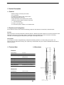
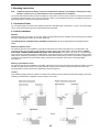
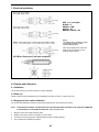
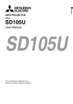
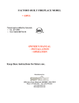
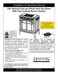
INTEMPCO Controls Ltd.
880 Selkirk Avenue
Pointe-Claire (Quebec) Canada H9R 3S3
Tel.: (514) 426-0488 Fax : (514) 426-0522
Email: [email protected]
www.intempco.com
USER MANUAL
LLS100 – LEVEL SWITCH
No. LSM112010 Rev 1
Safety Information
The described product must be installed by qualified personnel to applicable codes and operated as
described in this operating manual. Read it and understand it before installing and connecting the unit for
operation.
LLS100 Level Switch – User manual
No. LSM112010 Rev 1.0
1. Product Description
1.1 Features
• Miniature design conductivity level switch
• No moving parts
• All wetted parts stainless steel 316 and Teflon
• Alternating potential electronics
• Single Pole Double Throw (SPDT) relay contacts
• Hermetically sealed vibration resistant construction
• 1 – 3 second time delay
• For high or low relay action
• For conductive liquids in metallic or non-metallic tanks
1.2 Function and Configuration
The LLS100 level sensors use conductive measuring principle for level detection of electrically conductive liquids.
Function
When the probe is covered by electrically conductive medium, it detects the product resistance. The circuit is closed and a low
alternating current flows from the probe, which is measured by the integral electronics and converted into a switching
command. The switching signal is determined by the length or mounting of the probe.
Configuration
The LLS100 is a miniature integrated design complete with switching electronics, enclosure, fitting and a probe. The
electronics are fully potted in the housing. The output is dry contacts SPDT relay. The LLS100 is available with lead wires or
or M12 connector.
1.3 Technical Data
1.4 Dimensions
Electrical
Supply Voltage :
12-32 VDC
Output :
SPDT relay, NO or NC
Maximum Load Charge:
1A @ 30 VDC
0.3A @ 125 VAC
Dampening :
1-3 seconds (standard)
Sensitivity :
10 K ohms (resistive fluids)
Circuit Protection :
Reverse Voltage
Probe Output :
1 mA max. 1 VAC max. @ 5 kHz
Operating temperature &
Storage temperature :
-40 oC to 85 oC (- 40 oF to 185 oF )
Mechanical
Wetted Material :
316 SS and Teflon
Mounting fitting :
1/4 ” NPT std., others available
Process Temperature :
100 oC max. ( 212 oF)
Process Pressure :
100 psi max. ( 6.9 bar )
Electrical Termination :
Lead wire or M12 male receptacle
Moisture Protection :
IP67 (NEMA 6 equivalent)
2/5
LLS100 Level Switch – User manual
No. LSM112010 Rev 1.0
2. Mounting Instructions
Note :
Unpack the instrument carefully. Inspect all components for damage. If any damage is found, please notify
Intempco Controls Ltd. or its representative as soon as possible prior to installation.
The LLS100 level switch should be located, if possible, for easy access for service. Sensor enclosure should not be exposed
to ambient temperatures below -40°C (-40°F) or above 85°C (185°F). It is preferable the switch is not installed in proximity to
high voltage wires or other sources of high electrical noise.
2.1 Conductive Probes
For conductive liquids, LLS100 uses bare stainless steel probe. Standard length of the probe is 1” (2.5cm). The probe length
can be customer specified for the level of liquid desired to be measured.
2.2 LLS100 Installation
General
Standard probe entry into a tank is via 1/4” NPT opening but other fitting sizes are available. When mounting the level switch it
should be noted that the rod does not touch the vessel wall.
TO SCREW IN SWITCH (THREADED ENTRY) USE WRENCH ON HEX ONLY. Do not use a pipe wrench on the body of the level
switch.
Mounting in Metallic Vessel
The reference ground for this installation is typically the metal wall of the vessel, especially for top mounted probes. Use
conductive sealant, such as copper on NPT threads, if possible. When using Teflon sealant, make sure there is a GOOD
ELECTRICAL CONNECTION BETWEEN THE VESSEL AND THE FITTING of the switch. Use ground or conductivity tester
(ohm meter). For horizontally or bottom mounted probes, the reference ground is not as important since the change in switch
output can be achieved by liquid being in contact with the probe and the switch fitting. However, the sensitivity is higher if the
grounding is good between the vessel and the fitting, and therefore the operation of the switch is more dependable
(see Figure 1).
Mounting in Non-Metallic Vessel
The reference ground for this installation is the fitting of the switch. The circuit is closed when the conductive liquid is in contact
with both the probe and the fitting. A horizontally mounted rod type probe should be mounted so that the lower face of the
probe is parallel to and at the level of the desired alarm point (see Figure 2).
Location
Avoid installing rod type probes in nozzles or recesses where material can accumulate and cause false readings. Also avoid
installing the LSS100 close to agitators or moving objects in the vessel.
Figure 1
Figure 2
3/5
LLS100 Level Switch – User manual
No. LSM112010 Rev 1.0
3. Electrical Installation
RED = V+ (12-32 VDC)
BLACK = VGREEN = COM
WHITE = NC
BROWN or BLUE = NO
NOTE:
12 -32 VDC power is standard. For other
power supply voltages, a power
converter must be used.
APPLYING POWER OTHER THAN THAT
MEANT FOR THE UNIT MAY CAUSE
DAMAGE AND/OR INJURY.
M12 Micro-Connector 5-pin male receptacle
4.0 Startup and Calibration
4.1 Calibration
The LLS100 is factory per-set and requires no further calibration
4.2 Power-up
After the switch has been installed as per the installation procedure in section 3, power up the unit.
4.3 Single point level switch calibration
The LLS100 test calibration procedures require that the liquid level in the vessel may be varied.
NOTE : FOR HORIZONTAL PROBES, CALIBRATION SHOULD BE DONE REQUIRING THE PROBE TO BE COMPLETELY IMMERSED
IN THE MATERIAL AT THE DESIRED ALARM POINT. Follow the steps below.
1.
2.
3.
4.
Bring the level in the vessel below the probe.
Raise the level in the vessel to completely cover the probe.
The RELAY should change state, indicating that the switch is working properly.
This completes the calibration procedure.
4/5
LLS100 Level Switch – User manual
No. LSM112010 Rev 1.0
NOTE : FOR VERTICAL PROBES, CALIBRATION TEST SHOULD BE DONE WITH THE LEVEL JUST IN CONTACT WITH THE
PROBE. Follow the steps below.
1.
2.
3.
4.
Bring the level in the vessel below the probe.
Raise the level in the vessel to be just in contact with the probe.
The RELAY should change state, indicating that the switch is working properly
This completes the calibration procedure.
It is the policy of INTEMPCO to comply with all worldwide safety and EMC/EMI regulations that apply. INTEMPCO is constantly pursuing certification of its
products to the European New Approach Directives. INTEMPCO will add the CE mark to every appropriate device upon certification. The information contained in
this document is believed to be correct, but INTEMPCO Controls, Ltd. accepts no liability for any errors it contains, and reserves the right to alter specifications
without notice.
WARNING : These products are not designed for use in, and should not be used for, patient-connected applications
WARRANTY / DISCLAIMER
INTEMPCO Controls, Ltd. warrants this unit to be free of defects in materials and workmanship for a period of 13 months from date of purchase. INTEMPCO
warranty adds an additional one (1) month grace period to the normal one (1) year product warranty to cover handling and shipping time. This ensures that
INTEMPCO.s customers receive maximum coverage on each product.
If the unit malfunctions, it must be returned to the factory for evaluation. INTEMPCO.s Customer Service Department will issue an Return Merchandise Authorized
( RMA ) number immediately upon phone or written request. Upon examination by INTEMPCO, if the unit is found to be defective, it will be repaired or replaced at
no charge. INTEMPCO’s WARRANTY does not apply to defects resulting from any action of the purchaser, including but not limited to mishandling, improper
interfacing, operation outside of design limits, improper repair, or unauthorized modification. This WARRANTY is VOID if the unit shows evidence of having been
tampered with or shows evidence of having been damaged as a result of excessive corrosion; or current, heat, moisture or vibration; improper specification;
misapplication; misuse or other operating conditions outside of INTEMPCO.s control. Components which wear are not warranted, including but not limited to
contact points, fuses, and triacs.
INTEMPCO is pleased to offer suggestions on the use of its various products. However, INTEMPCO neither assumes responsibility for any omissions
or errors nor assumes liability for any damages that result from the use of its products in accordance with information provided by INTEMPCO, either
verbal or written. INTEMPCO warrants only that the parts manufactured by it will be as specified and free of defects. INTEMPCO MAKES NO OTHER
WARRANTIES OR REPRESENTATIONS OF ANY KIND WHATSOEVER, EXPRESS OR IMPLIED, EXCEPT THAT OF TITLE, AND ALL IMPLIED
WARRANTIES INCLUDING ANY WARRANTY OF MERCHANTABILITY AND FITNESS FOR A PARTICULAR PURPOSE ARE HEREBY DISCLAIMED.
LIMITATION OF LIABILITY: The remedies of purchaser set forth herein are exclusive, and the total liability of INTEMPCO with respect to this order,
whether based on contract, warranty, negligence, indemnification, strict liability or otherwise, shall not exceed the purchase price of the component
upon which liability is based. In no event shall INTEMPCO be liable for consequential, incidental or special damages.
CONDITIONS: Equipment sold by INTEMPCO is not intended to be used, nor shall it be used: ( 1 ) as a “Basic Component” under 10 CFR 21 ( NRC ), used in or
with any nuclear installation or activity; or (2) in medical applications or used on humans. Should any Product(s) be used in or with any nuclear installation or
activity, medical application, used on humans, or misused in any way, INTEMPCO assumes no responsibility as set forth in our basic WARRANTY / DISCLAIMER
language, and, additionally, purchaser will indemnify INTEMPCO and hold INTEMPCO harmless from any liability or damage whatsoever arising out of the use of
the Product(s) in such a manner.
RETURN REQUESTS / INQUIRIES
Direct all warranty and repair requests/inquiries to the INTEMPCO Customer Service Department. BEFORE RETURNING ANY PRODUCT(S) TO INTEMPCO,
PURCHASER MUST OBTAIN AN AUTHORIZED RETURN (RMA) NUMBER FROM INTEMPCO CUSTOMER SERVICE DEPARTMENT (IN ORDER TO AVOID
PROCESSING DELAYS). The assigned RMA number should then be marked on the outside of the return package and on any correspondence.The purchaser is
responsible for shipping charges, freight, insurance and proper packaging to prevent breakage in transit.
FOR WARRANTY RETURNS, please have the following information
available BEFORE contacting INTEMPCO :
FOR NON-WARRANTY REPAIRS, consult INTEMPCO for current repair
charges. Have the following information available BEFORE contacting
INTEMPCO :
1. Purchase Order number under which the product was PURCHASED,
2. Model and serial number of the product under warranty, and
3. Repair instructions and/or specific problems relative to the product.
1. Purchase Order number to cover the COST of the repair,
2. Model and serial number of product, and
3. Repair instructions and/or specific problems relative to the product.
INTEMPCO’s policy is to make running changes, not model changes, whenever an improvement is possible. This affords our customers the
latest in technology and engineering.
INTEMPCO stands for INTEMPCO Controls, Ltd.
5/5