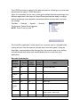
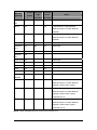
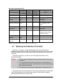
1
HT650 Rugged Handheld Terminal
- HT650 -
User’s Manual
400992G Version 0.2
Handy Terminal User Guide
2
Table of Contents
Charpt 1. References ....................................................................................... 1
1.1. General Use And Product Safety...................................................... 1
1.2. Federal Communication Commission Interference Statement.......... 3
1.3. SAR Compliance .............................................................................. 4
1.4. WEEE Compliance ........................................................................... 4
1.5. System Specifications....................................................................... 5
1.6. Environment Standard ...................................................................... 7
1.7. Warranty And After Service............................................................... 7
Charpt 2. Introduction....................................................................................... 9
2.1. Package Contents ............................................................................ 9
2.2. General View .................................................................................. 10
2.2.1. Handy Terminal Front Side View.......................................... 10
2.2.2. Handy Terminal Back Side View .......................................... 10
2.3. Keypad Description ........................................................................ 12
2.3.1. The Soft Keypad .................................................................. 13
2.4. Scanning Barcode .......................................................................... 14
2.5. Resetting the Handy Terminal......................................................... 15
2.5.1. Software (Warm) Reset ....................................................... 15
2.5.2. Cold Reset ........................................................................... 15
2.6. Saving to Flash............................................................................... 16
Charpt 3. Getting Started................................................................................ 17
3.1. Charging the Battery Pack.............................................................. 17
3.1.1. Installing the battery pack .................................................... 17
3.1.2. Charging the battery pack with Power Adapter .................... 18
3.1.3. Charging the battery pack with Single Dock ........................ 19
3.2. Starting the Handy Terminal............................................................ 20
3.3. Power (and Backlight) on / off......................................................... 20
3.4. Navigating the Display.................................................................... 21
3.4.1. The Command Bar .............................................................. 21
3.4.2. The Task Bar........................................................................ 21
3.4.3. Using the Stylus ................................................................... 22
3.5. Calibration of the touch Screen ...................................................... 22
3.6. Control Panel.................................................................................. 23
3.6.1. Barcode Setting ................................................................... 23
3.7. Backup and Restore Function ........................................................ 27
Charpt 4. Communication............................................................................... 29
4.1. Bluetooth Device ............................................................................ 29
4.1.1. Connect to a Bluetooth Printer or GPS ................................ 29
4.1.2. File transfer between two Terminals .................................... 31
4.2. Wi-Fi Network ................................................................................. 32
4.3. Microsoft® ActiveSync® ................................................................. 33
4.4. Federal Communication Commission Interference Statement........ 33
Charpt 5. Appendix ........................................................................................ 35
5.1. AIM Code Identifiers of Symbol SE955 .......................................... 35
Charpt 1. References
Reserves the right to make improvements or changes in the products
described in this document at any time without notices. While reasonable
efforts have been made in the preparation of this document to assure its
accuracy, assumes no liability resulting from any errors of omissions in this
guide, or from the use of the information contained herein. Further, reserves
the right to revise this publication and to make changes to it from time to
time without any obligation to notify any person or organization of such
revision or changes.
This document is copyrighted. All rights are reserved. This document may
not, in whole or in part, be copied, photocopied, reproduced, translated or
reduced to any electronic medium or machine-readable form without prior
consent, in writing.
1.1. General Use And Product Safety
Do not stare into the laser beam directly or shine it into eyes.
Never use strong pressure onto the screen or subject it to severe
impact, as the LCD panel could become cracked and possibility
cause personal injury. If the LCD panel is broken, never touch the
liquid inside, for such contact would irritate the skin.
Although the handy terminal has been passed the test of IP54
standard for water and dust resistance, avoid prolonged exposure
to rain or other concentrated moisture. For these conditions
exceed the IP54 standard, and could result in water or other
contaminants entering into the handy terminal.
Use only the approved AC Adapter with the Terminal. Use of an
unapproved AC Adapter could result in electrical problems, or
even cause a fire or electrical shock to the user.
Be sure that only authorized supplier are allowed to disassemble
and reassemble the device. If the device or parts has been
damaged due to any wrong handling, shall void the product and
parts warranty.
1
Always make back-up copies of all important data. Easy done by
using a cable or Single Cradle (sold by optional) to transfer data to
the computer. Manufacturer is not liable for any data damages or
data loss caused by deletion or corruption by using of this device,
or due to the drained battery.
Lithium-ion battery packs might get hot, explode, ignite and/or
cause serious injury if exploded by abusive using. Please follow
the safety warnings listed as below:
Do not place the battery pack in fire or heat the battery.
Do not install the battery pack backwards so the polarity is
reserved.
Do not connect the positive Battery pack with negative
battery pack to each other with any metal object (like wire).
Do not carry or store battery pack together with metal objects.
Do not pierce the battery pack with nails, strike the battery
pack with a hammer, step on the battery pack or otherwise put
it to strong impacts or shocks.
Do not solder directly onto the battery pack.
Do not expose battery pack to liquid, or allow the battery
contacts to get wet.
Do not disassemble or modify the battery pack. The battery
pack contains safety and protection devices, which, if
damaged, may cause the battery pack to generate heat,
explode or ignite.
Do not discharge the battery pack using any device except for
the specified device. When it is used in devices other than the
specified devices, the battery pack can be damaged or its life
expectancy reduced. If the device causes any abnormal current
to flow, it may cause the battery pack to become hot, explode or
ignite and cause serious injury.
In the event the battery pack leaks and the fluid gets into
one’s eye, do not rub the eye. Rinse well with water and
immediately seek medical care. If left untreated, the battery
fluid could cause damage to the eye.
2
1.2. Federal Communication Commission
Interference Statement
This device complies with Part 15 of the FCC Rules. Operation is
subject to the following two conditions: (1) This device may not
cause harmful interference, and (2) this device must accept any
interference received, including interference that may cause
undesired operation.
NOTS: This equipment has been tested and found to comply with the limits for
a Class B digital device, pursuant to Part 15 of the FCC Rules. These limits are
designed to provide reasonable protection against harmful interference in a
residential installation. This equipment generates, uses and can radiate radio
frequency energy and, if not installed and used in accordance with the
instructions, may cause harmful interference to radio communications.
However, there is no guarantee that interference will not occur in a particular
installation. If this equipment does cause harmful interference to radio or
television reception, which can be determined by turning the equipment off and
on, the user is encouraged to try to correct the interference by one of the
following measures:
Reorient or relocate the receiving antenna.
Increase the separation between the equipment and receiver.
Connect the equipment into an outlet on a circuit different from that
to which the receiver is connected.
Consult the dealer or an experienced radio/TV technician for help.
FCC Caution: Any changes or modifications not expressly approved by the party
responsible for compliance could void the user's authority to
operate this equipment.
IMPORTANT NOTE:
Radiation Exposure Statement:
This equipment complies with FCC radiation exposure limits set forth for an
uncontrolled environment. End users must follow the specific operating
instructions for satisfying RF exposure compliance. To maintain compliance with
FCC RF exposure compliance requirements, please follow operation instruction
as documented in this manual.
3
This transmitter must not be co-located or operating in conjunction with any
other antenna or transmitter.
1.3. SAR Compliance
This equipment has been SAR-evaluated for use in laptops (notebooks)
with side slot configuration.
Caution: Please also note that Terminal is limited in CH1~CH11
for 2.4GHz by specified firmware controlled in U.S.A.
The FCC ID of Handy Terminal is SPY-PDT
1.4. WEEE Compliance
This symbol is placed on the product to remind users to dispose of
Waste Electrical and Electronic Equipment (WEEEE) appropriately,
per Directive Europe 2002/96/EC. In most areas, this product can
be recycled, reclaimed and re-used when properly discarded. Do not
discard labeled units with trash.
4
1.5. System Specifications
Processor
Memory
Marvell PXA270 with 312 MHz 32 bits RISC
CPU
- 2GB Flash ROM
- 64 MB SDRAM
Display and Touch Panel - Trans-missive Micro Reflective 2.4” TFT
256K Color QVGA LCD with high brightness
LED backlight
- Resistive type touch panel (optional)
Audio
RF Radio
Support(Option)
- Wireless LAN
- Two buzzers
- 802.11b/g Wireless LAN
- Compliant with WPA and IEEE 802.11i
WPA2
- Cisco Compatible Extensions (CCX)
Version 4 certification
- Support full range of 802.1x(EAP) including
EAP-TLS, EAP-FAST, LEAP,
PEAP-MSCHAPv2 and PEAP-GTC
- Support Static, Pre-shared and Dynamic
encryption 40-bit and 128-bit keys. WEP,
WPA: TKIP and WPA2:AES
- Support coexistence with Bluetooth
RF Radio
Support(Option)
-Bluetooth WPAN
External Connect Ports
-- Class II with V2.0 compliant
-- Range 10 m
-- Support coexistence with WiFi
- One I/O connector support USB Client and
power input
- I/O connector supports connection for USB
cable, cradle and power adapter
- USB supports USB Client with USB 1.1
compliant
Scan Engine
Indicator
- Motorola SE955 1D laser scanner
- One two color LED for charger status
indicator
5
Red: Charging
Green: Fully charged
- One two color LED scanner indicator
Red: Scanning
Green: Good scan
Battery
- Standard battery pack: 1100mAH, 3.7V,
Li-Ion
- Extended battery pack: 2000mAH, 3.7V,
Li-Ion
- One rechargeable 15mAH, 2.4V Li-MH
backup battery
- One battery cover sensor switch
- Battery charge time:
1100mAH battery pack: 2.5 hours
2000mAH battery pack: 4.0 hours
Power Adapter
- 100~240Vac, 50/60Hz Input
- 5Vdc/3Adc, Wall Mount
Button/Key
- One 23-key numeric keypad
- Four function keys
- Two direction keys
- One scan key
- One power button
Dimensions
Weight
135(L) x 50(W) x 25(H) mm
170g including 1100mAH battery pack
190g including 2000mAH battery pack
Software
- WinCE 5.0 Core Version
- Backup manager, Scanner Setting utility,
- SDK and BSP development software
6
1.6. Environment Standard
Storage Temperature
-25℃ ~ 60℃
Operation Temperature
-10℃ ~ 50℃
Humidity
Free Drop
Tumble Drop
Environmental Sealing
ESD
Regulatory Compliance
95% non-condensing @ 40℃
1.2m (4ft) drop to concrete, 3 drops per 6
surfaces
100 times 2 feet tumbles (200 drops)
IP54 Standard
+/-8KV Air Discharge, +/-4KV Contact
Discharge
CE, CB, FCC, NCC, SRMC, CCC
1.7. Warranty And After Service
Should this Handy Terminal be malfunctioned, please contact your original
retailer providing information about the product name, the serial number, and
the details about the problem.
7
8
Charpt 2. Introduction
Congratulations on purchasing the Terminal, a Microsoft Windows®
CE .Net rugged Terminal. It’s special combination of features make it perfect
for using in a wide range of applications. These features as :
Small rugged lightweight form factor
Microsoft Windows® CE .Net 5.0 core operating system
Flexible module design
Wireless mobility via Bluetooth (802.11b/g by optional)
Robust expansion capability
Trans-missive type color LCD display
2.1. Package Contents
Open the package and check all the parts are inside without shortage and
damage:
No.
Item
Notes
1.
Handy Terminal
Standard
2
Quick Guide
Standard
3.
Standard Battery Pack (1100mAH)
Standard
4.
Power Adapter
Standard
5.
USB Y Cable
Standard
6.
Hand Strap
Standard
7.
Stylus
Standard
9
2.2. General View
2.2.1. Handy Terminal Front Side View
Figure 2-1
2.2.2. Handy Terminal Back Side View
Figure 2-2
10
Table 2-1 Description of Terminal General View
1
2
Scanner LED Indicator “Red” color
Scan is in progress
“Green” color
Scan is reading successful
Charge LED
Indicator
“Red” color
Battery Pack is still charging
“Green” color
Battery Pack is charged full
3
LCM/ Touch Panel
Do specific action through touch panel by stylus
4
Scan key
Start scanning the barcode by pressing the scan
key
5
Power key
6
Fun key(
Turns on the system resume or turn off the
system suspend, if this power key button is
pressed.
1. This key is used to combination with other
keys to type special character or perform
system functions
)
7
Navigation key(
)
8
Alpha-Numeric keys
9
Alpha key
2. The status icon of task bar will display like
when it is orange function mode.
Combine fun Key and Navigation keys for left,
right, up and down directions
Numeric keys, Change to Alpha keys after
pressing Alpha key.
1. Toggle Alpha-mode for Alpha-Numeric keys
2. The status icon of task bar will display like
11 Enter key
when it is Alpha mode.
1. This key is used to combination with other
keys to type special character or perform
system functions.
2. The status icon of task bar will display like
when it is blue function mode.
This key confirms data entry
12 DC power /USB
Synchronization port
A connector to support DC power, USB
Synchronization functions
13 Barcode window
A window for scanning of barcode reader
14 Stylus
Use the stylus for selecting items and entering
information.
15 Battery cover
Protect Battery pack, keep the switch of battery
cover to leave system from suspend mode
16 Battery cover latch
To keep Battery Cover locked
17 Hand strap
This strap can be sealed tighter or looser
10 Fun key (
)
11
2.3. Keypad Description
Figure 2-3
[SCAN]
[ENT]
Scanning barcode
The Enter key confirms data entry.
[FUNC] The Function Key is used in conjunction with specific number keys to
operate as Hotkeys.
[ESC]
The escape key returns the user to a previous page.
[Cursor] The cursor key moves the cursor around the screen.
[Alpha]
The Alpha key toggles Alpha mode on and off and Caps mode on and
off. One press of the Alpha key causes the keys to input alpha
characters.
12
2.3.1. The Soft Keypad
In applications that accept keypad input, the soft input panel (SIP) can be
used to enter data using the stylus. The SIP is digital, QWERTY-Style
keyboard ( See Figure 2-4 ).
To open the SIP, tap the keyboard icon (
) to open the menu and
select Hide Input Panel to close the keyboard.
Use the stylus to select letters, numbers, or symbols from the Soft Input
Panel for the current application(see Figure 2-5).
Figure 2-4
Figure 2-5
13
2.4. Scanning Barcode
To use the scanning function, complete the following steps:
1.
Press the scan key. The scanner scans as long as you hold the key
or for few seconds.
2.
Upon reading a barcode, the red LED indicator comes on until the
trigger is release or few seconds. The green LED and the beep tone
indicate a good read.
3.
Aim the scanning beam at the center of barcode.
4.
Barcode Scanning Position
This device can read from 40mm to 300mm distance.
a) Position the laser scanner close to the barcode when scanning
small barcodes. And position it is a distance from the barcode
when scanning large barcodes
b) The reader can be detected by a red beam.
5.
Bad Scanning Position
a) Make sure that the bars enter the laser beam when scanning
large barcodes.
b) Scanning operations may fail if the laser beam position as below.
Note:
This product scans using laser light. Never look directly into
the laser light or shine the laser light into the eyes
14
2.5. Resetting the Handy Terminal
2.5.1. Software (Warm) Reset
A warm reset is a transition from the on, idle, or suspend power state that
close all applications, clears the working RAM, but preserves the file
system.
Reason to Warm Reset:If an application “hangs”, initiate a warm reset
to terminate the application only.
Procedure to Warm Reset:To initialize a warm reset, press and hold the
<
>&<
> key.
Note: After Warm Reset:
The desktop appears with the application shortcuts on
the screen.
The custom settings in the registry are persistent.
The wireless will reconnects to the network system.
2.5.2. Cold Reset
1.
You can use Cold Reset to initiate device if WINCE.NET OS lock up
or Warm Reset still can’t work
2.
To perform Cold Reset, please press <
>&<
>&<
> key
simultaneously until Cold reset start.
3.
Device will initiate boot up after Cold Reset.
Caution:
Please press the <ESC> & <Power> key first. Try
warm reset before you initiate Cold Reset. All
applications will be Closed and working RAM and all
files will be cleared if you initiate the Cold Reset. It’s
better install your application and files to StorageCard
folder.
15
2.6. Saving to Flash
The StorageCard folder let the application or a data file can be stored into
the Flash Memory. To save an application or data to the Flash Memory, from
your current application, select File
Save As
select the StorageCard
location and save it.
You can use backup manager form start
program
backup manager
to backup all system and save it to the StorageCard folder after you install
your application program and do the all setting complete.
Note:
The StorageCard storage memory persists all reset
(warm/cold reboot) conditions and software/firmware updates.
We strongly recommend installing all applications, applets,
programs, and important data files to the StorageCard
location.
Caution: If an application or a data file is only installed or saved in RAM,
a hard reset will result in the loss of that application or data file.
The size of the Flash Disk folder will vary, depending on the size of
system firmware。
Inside of My Device please select StorageCard icon, then tap File
Properties。
The StorageCard Properties dialog will display the size of
StorageCard folder。
Note : IT9000 will include 2GB Micro SD card , please don’t remove it.
and must have systemtool folder on the storage card.
16
Charpt 3. Getting Started
3.1. Charging the Battery Pack
Before using the Handy Terminal, perform the basic procedure of
charging the battery pack through the following steps.
3.1.1. Installing the battery pack
1. Turn the switch cover latch and lift the battery cover away from the
Handy Terminal.
17
2. Turn the switch cover latch and lift the battery cover away from the
Handy Terminal.
3. Insert the battery pack into the battery compartment with the label
facing out, and ensuring the battery snaps into place
4. Replace the battery cover by insert the top first, switch lock the battery
cover latch to secure the cover to the Handy Terminal.
5. Charge time. For the first time to charge the battery pack needs
approximately 5 hours. Subsequent charging time needs
approximately 3 hours.
Caution: When charging the battery pack, the Power LED on the Handy
Terminal turns on Red. After the battery pack is fully charged,
the Power LED turns to green.
3.1.2. Charging the battery pack with Power
Adapter
1. Plug in the DC-IN Converter to the Handy Terminal bottom connector
2. Connect the Power cord to the Power adapter
3. Plug in the connector of the power adapter with DC-IN Converter
4. Connect the power cord to a power source
18
3.1.3. Charging the battery pack with Single
Dock
a) Do not leave the battery pack inside of the Handy Terminal
1. Connect the Power cord to the Power adapter
2. Connect the power cord to a power source
3. Plug in the connector of the power adapter with Single Dock
4. Insert the Handy Terminal into the Single Dock
b) Place the spare battery pack into the Single Cradle’s spare Battery
charging slot
1. Connect the Power cord to the Power adapter
2. Connect the power cord to a power source
3. Plug in the connector of the power adapter with Single Cradle
4. Insert the Battery pack into the Single Cradle’s spare Battery slot
Caution: When charging the battery pack, the Power LED on the Handy
Terminal turns to Red. After the battery pack is fully charged,
the Power LED turns to Blue.
Caution: Please don’t remove the Battery pack too long from Handy
Terminal after you have already full-charged the Battery pack
and backup battery pack and start to use the Handy Terminal.
Otherwise the data stored inside SDRAM memory will be lost.
Please also keep in mind power the Handy Terminal off if you
want to change the main Battery pack.
19
3.2. Starting the Handy Terminal
Press the Power key to turn on/off the Handy Terminal. If the Handy
Terminal does not power on, please perform a cold boot. See 2.5 Resetting
the Handy Terminal on page 22
Caution: When a battery is fully inserted in Handy Terminal for the
first time, upon the Handy Terminal’s first power up, the
device boots and powers on automatically.
When the Handy Terminal is
powered on for the first time, it
initializes its system.
A splash screen appears for a
short period of time followed by
the Wince.NET 5.0 window.
3.3. Power (and Backlight) on / off
Press the Power/Backlight key briefly (
). If the Handy Terminal does not
power on, please perform the cold reset.
As the Handy Terminal initializes its File system, the Terminal splash screen
displays for about 30 seconds.
To turn off the Handy Terminal, just press the Power/Backlight key again.
This action does not actually turn off the Handy Terminal, it only turn the Handy
Terminal into suspend mode. All running applications remain as you left them,
until you press the Power key again to resume operation of the Handy Terminal
20
3.4. Navigating the Display
3.4.1. The Command Bar
Use the Command bar at top of the screen to perform tasks in programs,
such a opening a file, or editing a file.
3.4.2. The Task Bar
The Task bar at the bottom of the screen displays the icon, an icon for the
active program, the current time, and system icons for utilities loaded in
memory. The Task bar includes menu names, buttons, and the keyboard
icon, which opens and closes the soft input panel (SIP). The Task bar
allows you to select and close programs. Refer to Figure 3-1 to view the
Task bar.
Command Bar
Task Bar
Figure 3-1
21
3.4.3. Using the Stylus
The stylus function like a mouse, hold the stylus like a pen or pencil. You
can do action as follow.
Double Tap:Touch the icon twice on the screen to open or execute
it.
Drag:Firmly press the icon on the screen to drag across the
screen.
Caution: Never use an actual pen, pencil, or sharp/ abrasive object to write
on the touch screen.
Do not apply unnecessary high pressures on the screen.
3.5. Calibration of the touch Screen
On the initial boot-up of the Handy
Terminal, the stylus calibration screen
(Labeled Align Screen) opens. Use
the stylus to press and hold briefly on
the center of each target as it moves
around the screen.
If necessary, adjust the backlight
on the Handy Terminal to make the
screen readable.
When you feel the touch screen
function is poor or the operation does
not match the exact location it should
be, please recalibrate the screen by
using the stylus to tap the Start Settings
the “Calibration” to recalibrate again
22
Control Panel
Stylus, to open
3.6. Control Panel
From the Desktop, double click the “My Device” icon then double click the
“Control Panel” icon to open the Windows CE 5.0 control panel. The
control panel can be launched from Start
Settings
Control panel also.
All applet programs are displayed as a icon on the screen.
Notes: Please make sure that StorageCard folder have a subfolder name
“systemtool” after firmware version v1.20. And some execute files of control
panel are store to systemtool folder.
Figure 3-2
3.6.1. Barcode Setting
The HT650 has an integrated laser scanner, which reads all major 1D barcode
labels with excellent performance.
NOTE: The reading software must be enabled in order to operate the scanner.
This can be a user-loaded application or a pre-loaded utility such as
Scanner Settings or Scan2Key.
23
To launch the Scanner Control Panel, follow these instructions:
1. Tap Start → Settings → System
2.
Tap the Scanner icon. The
Scanner Control Panel appears.
NOTE: Or press Func key and “7”
simultaneously to bring up the
Scanner Control Panel screen.
In the Scanner Control Panel screen, you can configure barcode scanner
parameters such as enabling or disabling barcode symbologies, setting data
transmission options, configuring magnetic and proximity reading options, and
setting power management options. See the section of Barcode Symbologies.
To test the barcode laser scanner, follow these instructions.
1. Tap the Test tab to activate the demo program.
2. Tap Tools → Enable Scan.
Or tap Tools → Auto-Scan →
Start Auto-Scan.
Define the scan interval. Tap Start.
3.
Aim the laser scanner at the
selected barcode, and press
either one of the scanner trigger
buttons on the device.
If you enable Auto-Scan, you don’t
have to press any button. Aim the
laser scanner at the selected
barcode while the laser emits light at regular intervals. The scanned
barcode data appears on the screen.
4.
Tap Tools → Auto-Scan → Stop Auto-Scan.
24
The HT650 provides an option for the barcode scanner, allowing you to scan and
decode various types of 1D/2D barcodes.
When it is necessary for the user to change the default barcode symbology for a
different application, the Scanner Control Panel provides the ability to change
default symbology, place delimiter characters behind scanned data, and save
the settings.
Tap Start → Settings → System → Scanner.
The Scanner Control Panel appears.
NOTE: Press Func key and “7”.
The Scan2Key application routes input from a scanner port to a keypad buffer,
making all input from the scanner emulate input from the keypad. Using the
Scan2Key, scanned data will be directed from the scanner port to any waiting
(active/focused) text editor such as MS Mobile Word or a text box in an
application.
Barcode Symbologies
Enable Char Check Transmit
/
/ Digit
Check
Disabl
e
verification Char/digit
Barcode
Symbology
Australian
YES
Others
Send bar width data
Post
British Post YES
Canadian
YES
Post
Codabar
YES
YES
Code 11
YES
YES
Code
YES
YES
Transmit start & stop char, *data length
*data length
*data length
128/EAN
128
Code 39
YES
YES
YES
For ASCII, Transmit start & stop char,
Append mode, *data length
Code 93
YES
*data length
25
Enable Char Check Transmit
/
/ Digit
Check
Disabl
e
verification Char/digit
Barcode
Symbology
Others
Dutch (KIX) YES
Post
EAN 13
YES
YES
2 digit addenda, 5 digit addenda,
Addenda required, Include addenda
separator
EAN 8
YES
YES
2 digit addenda, 5 digit addenda,
Addenda required, Include addenda
separator
IATA 2 of 5
YES
Interleaved YES
*data length
YES
YES
*data length
2 of 5
ISBT
YES
Japanese
YES
Post
Korean Post YES
*data length
Matrix 2 of 5 YES
*data length
MSI
YES
YES
Planet
YES
YES
Postnet
YES
YES
RSS
YES
*data length
*data length
(Databar)
UPC A
YES
YES
2 digit addenda, 5 digit addenda,
Addenda required, Include addenda
separator, Send number system
UPC E
YES
YES
2 digit addenda, 5 digit addenda,
Addenda required, Include addenda
separator, Send number system,
Expanded UPC-E
UPC E1
YES
YES
2 digit addenda, 5 digit addenda,
Addenda required, Include addenda
separator, Send number system,
Expanded UPC-E
NOTE: *Value Adjustable Scanner Control Panel Version 5.14
26
Barcode Symbologies 2D
Enable
/
Disable
Barcode Symbology
Char Check
Transmit
/ Digit
Check
verification
Char/digit
Others
Aztec
YES
Runes, *data length
Codablock F
YES
*data length
Code 49
YES
*data length
Data Matrix
YES
*data length
EAN-UCC Composite YES
UPC composite, *data
length
MaxiCode
YES
*data length
MicroPDF417
YES
*data length
OCR
YES
OCR mode, OCR direction,
Template, Group G, Group
H, Check character
PDF-417
YES
QR Code
YES
*data length
TLC-39 (TCIF Linked YES
Code 39)
NOTE: *Value Adjustable Scanner Control Panel Version 5.14
3.7. Backup and Restore Function
Tap Start
Program
Backup Manager, the SunnySoft Backup
Manager program be executed. The system administrator cans choice Easy
Mode or Advanced Mode to backup all system or backup the folders what
you want.
The backup directory can be choice to StorageCard folder or My
Documents folder.
Notes: 1. The file on the StorageCard folder will permanent exist even
cold reset.
2. You can enable auto restore procedure on control panel, if
you enable auto restore, it will execute auto restore procedure
after system cold reset.
3. The system will auto backup after power is lower then 10%.
The backup file is an execution file. The system administrator can double
click the backup file icon to restore the system. After restore complete
please press OK button to warm reset.
27
If customer set enable “auto restore” item of Auto Restore on control
panel. The system will execute restore procedure after cold reset. The Auto
Restore function only accept the iBackup.bkp which is generated by Simple
mode of Backup manager
If you need more information please reference sunnysoft backup
manager user manual.
Figure 3 - 5
28
Charpt 4. Communication
4.1. Bluetooth Device
The system administrator has discovered and paired with a Bluetooth
device from OBEX tools of Terminal. The system administrator can assign a
friend name for Terminal that default friend name is “WindowsCE”.
The OBEX tools is an application for Bluetooth manager of IT9000, That
support FTP, Serial, Printer profile of Bluetooth. The OBEX tools support file
transfer between two Terminals by Bluetooth connection. More information
please reference OBEX tools user manual.
Notes:
Start
icon.
settings
control panel
double click the “system”
The system administrator can assign a device name from
“Device Name” Page, default is “WindowsCE”。
You can disable Bluetooth function from wireless
communication of Control Panel
4.1.1. Connect to a Bluetooth Printer or GPS
The administrator can perform procedure as follow to communication with
Bluetooth device and Terminal.
Double click the “OBEX tools” icon from control panel.
Tap the “Connect “ from menu
Tap the “Search Device” to discovery the Bluetooth device nearby the
Terminal.
Select the Bluetooth device that you want pair.
Select the “Printer Device“ or “GPS Device” depend on the device,
then press “Ok” button. And pop-up a message window to display the
connect port name.
After connect complete, the customer can open the Bluetooth port by
application.
29
Figure 4-1
30
4.1.2. File transfer between two Terminals
The role of one terminal must set as “server” from OBEX tools, and
another must set as “client”.
The role of server can be assigned a folder ( Ex “StorageCard” folder ) to
share for client. The role of client can assign a file path to link the Server
folder.
31
If connect ok between two Terminals , the Client will display the folder of
server, you can create a folder , delete a folder , sent a file from client to
server ….
4.2. Wi-Fi Network
Terminal Wi-Fi 802.11 b/g model can communicate with the host
computer using the on-board radio frequency component and Access point.
or
at Task bar, then a Wireless LAN screen
To tap the icon
“WLAN Manager” appear, select “Wireless information” page. There is a list
of Wireless access points, double click the access point on the list that you
want connect , set up the Encryption, Authentication, Network key items
according the access point setting.
To tap the icon
at the Task bar, then the “Summit client utility”
appear, you can change active profile by default or ThridPartyConfig.
32
The default admin password is “SUMMIT”.
The on-board radio frequency component of Terminal has an utility, it
is visible on the desktop, please tap the “Summit Client utility” icon. You can
find more information about this applet for the radio configuration from
http://www.summitdatacom.com/SCU.htm.
4.3. Microsoft® ActiveSync®
Microsoft ActiveSync is a file transfer tool that has possibility to connect
with a host pc and a Terminal and synchronize the files on them. You can
establish an ActiveSync connection between host pc and Terminal through
the following electrical interfaces.
USB interface:either directly or through the single cradle.
When the Terminal connect with host PC by USB interface, the Microsoft
ActiveSync start running, you were prompted to create a partnership with
your mobile device. When you set up a partnership, you can select
synchronization and file conversation settings, which are contained in a file
on your desktop computer. This file enables your desktop computer to
recognize your device. Only devices that have a partnership with a desktop
computer can synchronize information between the two computers.
For more information on partnerships, please refer to your Microsoft
ActiveSync documentation or help file.
4.4.
Federal Communication Commission Interference Statement
This equipment has been tested and found to comply with the limits for
a Class B digital device, pursuant to Part 15 of the FCC Rules. These limits
are designed to provide reasonable protection against harmful interference in
a residential installation. This equipment generates, uses and can radiate
radio frequency energy and, if not installed and used in accordance with the
instructions, may cause harmful interference to radio communications.
However, there is no guarantee that interference will not occur in a particular
installation. If this equipment does cause harmful interference to radio or
television reception, which can be determined by turning the equipment off
and on, the user is encouraged to try to correct the interference by one of the
following measures:
33
-
Reorient or relocate the receiving antenna.
Increase the separation between the equipment and receiver.
Connect the equipment into an outlet on a circuit different from that to
which the receiver is connected.
Consult the dealer or an experienced radio/TV technician for help.
FCC Caution: Any changes or modifications not expressly approved by
the party responsible for compliance could void the user's authority to
operate this equipment.
This device complies with Part 15 of the FCC Rules. Operation is subject
to the following two conditions: (1) This device may not cause harmful
interference, and (2) this device must accept any interference received,
including interference that may cause undesired operation.
IMPORTANT NOTE:
Radiation Exposure Statement:
This equipment complies with FCC radiation exposure limits set forth for
an uncontrolled environment. End users must follow the specific operating
instructions for satisfying RF exposure compliance. To maintain compliance
with FCC RF exposure compliance requirements, please follow operation
instruction as documented in this manual.
This transmitter must not be co-located or operating in conjunction with
any other antenna or transmitter.
34
Charpt 5. Appendix
5.1. AIM Code Identifiers of Symbol SE955
The follow information come from Symbol SE955 technical menu, if you need
more information please reference Symbol SE955 technical menu:
Each AIM Code identifier contains the three-character string ]cm where:
]= Flag Character(ASCII 93)
c = Code Character ( See as follow)
A: Code39
C: Code 128
E: UPC/EAN
F: Codabar
G: Code93
H: Code11
I : Interleaved 2 of 5
M: MSI
S : D2 of 5, IATA 2 of 5
X: code39 Trioptic , Bookland EAN
e: RSS
m = Modifier Character( See as follow table )
The modifier character is the sum of the applicable option values
based on the following tables.
Code Option Value
Type
Code39
0
1
3
4
Option
No Check character of Full ASCII processing
Reader has checked one check character.
Reader has checked and stripped check character.
Reader has performed FULL ASCII character
conversion.
Reader has performed FULL ASCII character
5
conversion and checked one check character.
Reader has performed FULL ASCII character
7
conversion and checked and stripped check
character.
Example: A Full ASCII bar code with check character W, A+I+MI+DW,
is transmitted as ]A7 Aim Id where 7=(3+4)
Trioptic Code 39
0
No option specified at this time, Always transmit 0.
Example: A trioptic bar code 412356 is transmitted as ]X0412356
Code 128
35
0
Standard data packet,No Function code 1 in first
symbol position.
1
Function code 1 in first symbol character position.
2
Function code 1 in second symbol character postion.
Example: A Code(EAN) 128 bar code with Function 1 character in the
first position, FNC1 Aim Id is transmitted as ]C1 AimId.
l 2 of 5
0
No Check digit processing.
1
Reader has validated check digit.
3
Reader has validated and stripped check digit.
Example:An l 2 0f 5 bar code without check digit,4123, is transmitted
as ]l04123
Codabar
0
No check digit processing.
1
Reader has checked digit
Example:A Codabar bar code without check digit, 4123, is transmitted
as ]F04123
Code 93
0
No options specified at this time, Always transmit 0.
Example: A Code 93 bar code 012345678905 is transmitted
as ]G0012345678905.
MSI
0
Mod 10 check digit checked and transmitted.
1
Mod 10 check digit checked but not transmitted
Example: An MSI bar code 4123, with a single check digit checked, is
transmitted as ]M04123.
D 2 of 5
0
No options specified at this time, Always transmit 0.
Example: A D2 of 5 bar code 4123, is transmitted as ]S04123.
UPC/EAN
0
Standard packet in full EAN country code format,
which is 13 digits for UPC-A and UPC-E( not including
supplemental data).
1
Two digit supplement data only.
2
Five digit supplement data only.
4
EAN-8 data packet.
Example: A UPC-A bar code 012345678905 is transmitted
as ]E00012345678905
Bookland EAN
0
No options specified at this time, Always transmit 0.
Example: A Bookland EAN bar code 123456789X is transmitted
as ]X0123456789X
According to AIM standard, a UPC with supplemental bar code is transmitted in
the following Format:
]E0(UPC chars)(terminator)]E2(supplemental)(terminator)
In the SE-955, however, the format is changed to:
]E0(UPC chars)]E2(sumpplemental)
36
Therefore, a UPC with two supplemental characters, 01234567890510, is
transmitted to the host as a 21-character string, ]E00012345678905]E110.
37