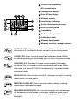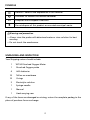
1
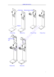
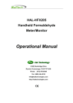
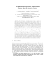
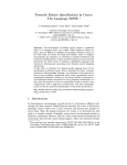
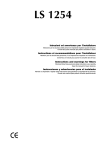
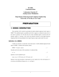
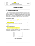
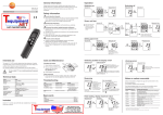
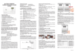
WT-50 Dissolved Oxygen Water Quality Meter Users Manual • • • • Mode d’emploi Bedienungshandbuch Manual d’Uso Manual de uso WT-50 Dissolved Oxygen Water Quality Meter English Users Manual September 2009, Rev.1 ©2009 Amprobe Test Tools. All rights reserved. Printed in China Limitation of Liability Your Amprobe product will be free from defects in material and workmanship for 1 year from the date of purchase. This warranty does not cover fuses, disposable batteries or damage from accident, neglect, misuse, alteration, contamination, or abnormal conditions of operation or handling. Resellers are not authorized to extend any other warranty on Amprobe’s behalf. To obtain service during the warranty period, return the product with proof of purchase to an authorized Amprobe Test Tools Service Center or to an Amprobe dealer or distributor. See Repair Section for details. THIS WARRANTY IS YOUR ONLY REMEDY. ALL OTHER WARRANTIES - WHETHER EXPRESS, IMPLIED OR STAUTORY INCLUDING IMPLIED WARRANTIES OF FITNESS FOR A PARTICULAR PURPOSE OR MERCHANTABILITY, ARE HEREBY DISCLAIMED. MANUFACTURER SHALL NOT BE LIABLE FOR ANY SPECIAL, INDIRECT, INCIDENTAL OR CONSEQUENTIAL DAMAGES OR LOSSES, ARISING FROM ANY CAUSE OR THEORY. Since some states or countries do not allow the exclusion or limitation of an implied warranty or of incidental or consequential damages, this limitation of liability may not apply to you. Repair All test tools returned for warranty or non-warranty repair or for calibration should be accompanied by the following: your name, company’s name, address, telephone number, and proof of purchase. Additionally, please include a brief description of the problem or the service requested and include the test leads with the meter. Non-warranty repair or replacement charges should be remitted in the form of a check, a money order, credit card with expiration date, or a purchase order made payable to Amprobe® Test Tools. In-Warranty Repairs and Replacement – All Countries Please read the warranty statement and check your battery before requesting repair. During the warranty period any defective test tool can be returned to your Amprobe® Test Tools distributor for an exchange for the same or like product. Please check the “Where to Buy” section on www. amprobe.com for a list of distributors near you. Additionally, in the United States and Canada InWarranty repair and replacement units can also be sent to a Amprobe® Test Tools Service Center (see below for address). Non-Warranty Repairs and Replacement – US and Canada Non-warranty repairs in the United States and Canada should be sent to a Amprobe® Test Tools Service Center. Call Amprobe® Test Tools or inquire at your point of purchase for current repair and replacement rates. In USA Amprobe Test Tools Everett, WA 98203 Tel: 888-993-5853 Fax: 425-446-6390 In Canada Amprobe Test Tools Mississauga, ON L4Z 1X9 Tel: 905-890-7600 Fax: 905-890-6866 Non-Warranty Repairs and Replacement – Europe European non-warranty units can be replaced by your Amprobe® Test Tools distributor for a nominal charge. Please check the “Where to Buy” section on www.amprobe.com for a list of distributors near you. Amprobe® Test Tools Europe In den Engematten 14 79286 Glottertal, Germany tel: +49 (0) 7684 8009 - 0 *(Correspondence only – no repair or replacement available from this address. European customers please contact your distributor.) WT-50 Dissolved Oxygen Water Quality Meter 1 Probe connection & IrDA ports 5 Operation keys 2 LCD display 6 Battery cover (rear side) 3 DC adaptor port 7 Tripod mount hole (rear side) 4 USB port 8 DO probe 1 Primary screen displays DO concentration 2 Temperature display 3 Date & Time display 4 Memory counter 5 Low battery indicator 6 Units of barometric pressure 7 Unit of salinity value 8 Freeze data 9 Stable readings indicator 10 Calibration mode 11 Memory Recall mode 12 Memory max/min./average review POWR/SET KEY: Press key to turn on and off the meter. When the meter is off, hold down for few seconds to enter setting mode CAL/ESC KEY: Press to switch normal and calibration mode. While in calibration, setting or recall mode, press to return to previous mode. HOLD/REC KEY: Press key to freeze current reading. Press again to unlock. Press >1 second to switch normal and recall mode. When the meter is off, press SET+HOLD simultaneously >1second to disable auto-sleep mode. MODE/UP KEY: Press this key to switch % and ppm (or mg/l). In setting mode, press to increase value. MEMORY/DOWN KEY: Press to record current reading. In setting mode, press to decrease the value. MAX/MIN/AV/ENTER KEY: Press to view the max./ min. and average of the memory in recall mode. In setting or calibration mode, press to confirm and enter next step. Press with HOLD/REC key to activate backlight. WT-50 Dissolved Oxygen Water Quality Meter CONTENTS SYMBOLS................................................................................................................2 UNPACKING AND INSPECTION..............................................................................2 INTRODUCTION......................................................................................................3 Features..............................................................................................................3 OPERATION . ..........................................................................................................3 Auto Power Off .................................................................................................4 Set Up.................................................................................................................5 Calibration Mode ..............................................................................................7 USB Interface Capabilities ................................................................................7 SPECIFICATION ......................................................................................................8 MAINTENANCE AND REPAIR.................................................................................9 To Replace membrance . ...................................................................................9 To Replace electrolyte solution.........................................................................10 TROUBLESHOOTING...............................................................................................10 APPENDIX...............................................................................................................11 MSDS of ELECTROLYTE..........................................................................................12 1 SYMBOLS � Caution ! Refer to the explanation in this Manual � Conforms to relevant Australian standards � Complies with European Directives = Do not dispose of this product as unsorted municipal waste. �Warning and precaution • Always rinse the probe with deionized water or rinse solution for best accuracy. • Do not touch the membrance. UnpAcking and Inspection Your Shipping carton should include: 1 WT-50 Dissolved Oxygen Meter 1 Dissolved Oxygen probe 4 AAA batteries 10 Teflon on membrane 10 O-rings 2 Electrolyte solution 1 Syringe needle 1 Manual 1 Hard carrying case If any of the items are damaged or missing, return the complete packag to the place of purchase for an exchange. 2 INTRODUCTION Thank you for purchasing WT-50 Dissolved Oxygen meter. The meter measures DO concentration with temperature compensation, salinity and pressure correction, which is an accurate instrument for water quality testing. The handy size and extension probe enables on-site testing and the memory and PC link function are also ideal for data collection and processing. Features • Accurate dissolved oxygen measurement • Salinity and barometric pressure compensation • 100% air saturation calibration • 99 point memory • Real time clock for data record • USB interface for data transmission OPERATION 1. Press “POWER/SET” to turn on and off the meter. 2. Press “MODE” to select DO scale between % and ppm (or mg/l). 3. Perform 100% air saturation calibration before measurement. (See page 7) If the stable readings (15 minutes after power on) are within 100%+/-0.5%, then no need to do the calibration. 4. Salinity and barometric pressure have effects on DO accuracy. The meter default is 760mmHg in pressure and 0.0ppt in salinity. Correct salinity value of water and barometric pressure in Setup P3.0 if the conditions of measuring site are different. 5. Immerse the probe head in the liquid and it display DO concentration on the LCD. Automatic Temperature Compensation takes several minutes to equalize temperatures of the probe and liquid and get stable readings. 6. Press “HLD/REC” in measuring mode to hold the current readings. HLD icon will be displayed on LCD. Press the button again to resume measuring. 7. Press “HLD/REC” and “MNX/AV” simultaneously to activate backlight. It turns off automatically after 10 seconds. 3 8. Switch READY indicator on or off in SETUP P4.0. When ready indicator is switch on, READY icon is fleshing on the left of screen while measuring and stops when reading gets stable. 9. Press “MEM” to store the current reading with real time information. The display will flash several times and the memory counter will increase by one. (Fig. 1) 10. Recall stored readings by pressing “HLD/REC” for 2 seconds. REC icon is flashing while reviewing data (Fig. 2). Press “MODE” or “MEM” to scroll through the memory counter. Or press “MNX/AV” to view Minimum, Maximum, and Average reading of stored data. Press “HLD/REC” again for 2 seconds to exit data recall mode. 11. Rinse the probe head with normal tap water after each measurement. Fig. 1 Fig. 2 Auto power off The meter turns off automatically after 40 minutes inactivity to save battery life. Users can set up desired time intervals (20, 30, 40, 60, 90, 120 minutes) for the sleep function in SETUP P5.0. To override the auto power off function, hold down “POWER/SET” and “HLD/REC” simultaneously to turn on the meter. It shows “nSL” on the screen and then enters measuring mode in non-sleep status. 4 Setup The advanced setup mode lets you customize your meter. 9 parameters are available in this model. P1.0: Clear memory P2.0: Select Units P3.0: Coefficient settings P4.0: Ready indication P5.0: Auto power off time P6.0: Real time clock P7.0: Beta (membrane temperature coefficient) P8.0: View Calibration data P9.0: Reset To enter SETUP mode, hold down “POWER/SET” for some seconds to turn on the meter. Press “MODE” or “MEM” to select parameters and press “MNX/AV/ENTER” (indicates “ENTER” in the following instructions) for parameter settings. To exit any setting, press CAL/Esc. Note: P0.0 Print function is not available in this model. P1.0: Clear memory In P1.0, press “ENTER” go into P1.1. Select "n"-NO or "y"-YES with “MODE” or “MEM” (Fig. 3), then press “ENTER” to confirm to clear all memories or not. P2.0: Select Units In P2.0, press “ENTER” to go into P2.1. Select temperature unit °F or °C with “MODE” or “MEM” and then press “ENTER” to P2.2 for selecting DO unit in mg/l or ppm. Press “ENTER” again to confirm the unit selection and return to P2.0. Fig. 3 5 P3.0: Coefficient settings In P3.0, press “ENTER” to go into P3.1 for changing barometric value in mmHg (default 760mmHg, see Fig. 4). Press “MODE” to increase and “MEM” to decrease the value. Press “ENTER” to P3.2 to change barometric value in kPA (default 101.3kPA) and P3.3 to change salinity value (default 0.0ppt). Press “ENTER” again to confirm the settings and go back to P3.0. (Check pressure in different altitude. See appendix) P4.0: Ready indication Press “ENTER” to go into P4.1 and press “MODE” or “MEM” to switch Ready indicator ON or OFF. (Fig. 5) P5.0: Auto power off time Press “ENTER” to go into P5.1, and select auto power off time with “MODE” or “MEM”. The options are 20, 30, 40, 60, 90,120 minutes. Press “ENTER” to complete the setting. P6.0: Real time clock In P6.0, press “ENTER” to go through P6.1 to P6.6 for date and time settings. Y-M-D and H:M:S will show in turn and corresponding digits will be flashing for further change. Press “MODE” to increase and “MEM” to decrease the numbers and press “ENTER” to confirm every setting. P7.0: Beta (membrane temperature coefficient) In P7.0, press “ENTER” to go into P7.1 and it displays default Beta temperature coefficient of the membrane 4.8 on the screen (Fig. 6). If different membrane is used, change the correct value with “MODE” or “MEM” and press “ENTER” to confirm the setting. P8.0: View Calibration data Press “ENTER” to go into P8.1. The LCD displays the latest calibration data Slope (sensor sensitivity) and time. Enter P8.2 to view calibration temperature. P9.0: Reset Press “ENTER” to go into P9.1. Select "n"-No or "y"-Yes with “MODE” or “MEM” for data reset to factory default. Press “ENTER” to confirm selection. Fig. 4 Fig. 6 Fig. 5 6 Calibration Mode It is required to perform 100% air saturation calibration before every measurement. Check the stable reading in 15 mins after power on. If it exceeds 100%+/-0.5% range, please performthe calibration in the followings: 1. Place the probe in the air and turn on the meter. 2. When DO reading is stable, press CAL/Esc to enter calibration mode. CAL icon will be flashing on the left side of LCD during calibration. (Fig. 7) 3. Wait for about 5 seconds or until the reading is stable, press “ENTER” to complete the calibration. Or terminate the calibration by pressing “CAL/Esc”. 4. If it is calibrated correctly, the meter will read approximately 100%. If the calibration is failed, “ERR#” is displayed on the screen. Repeat the calibration. USB Interface Capabilities The USB cable and software (optional kit) are required to transfer data to a PC. Install the USB driver in the software first before connection. And the connecting protocol is 9600 bps, 8 data bits, no parity. 7 SPECIFICATION D.O.% Range 0.0~199.9% Resolution 0.1% Accuracy ±1.5% of F.S. D.O.ppm Range 0.00~19.99ppm Resolution 0.01ppm Accuracy ±1.5% of F.S. Temperature Range 0~50 °C / 32~122°F Resolution 0.1°C Accuracy ±0.5°C Salinity Range 0.0~50.0ppt Resolution 0.1ppt Pressure Range 500~1499mmHg/66.6~199.9kPA Resolution 1mmHg/0.1kPA Memory point 99 point Power supply 4pcs AAA batteries � EMC: Conforms to EN61326-1. This product complies with requirements of the following EuropeanCommunity Directives: 89/ 336/ EEC (Electromagnetic Compatibility) and 73/ 23/EEC (Low Voltage) as amended by 93/ 68/ EEC (CE Marking). However, electricalnoise or intense electromagnetic fields in the vicinity of the equipment maydisturb the measurement circuit. Measuring instruments will also respond tounwanted signals that may be present within the measurement circuit. Usersshould exercise care and take appropriate precautions to avoid misleading results when making measurements in the presence of electronic interference. 8 MAINTENANCE AND REPAIR If there appears to be a malfunction during the operation of the meter, the following steps should be performed in order to isolate the cause of the problem. 1. Check the battery. Replace the battery immediately when the symbol “ ” appears on the LCD. 2. Review the operating instructions for possible mistakes in operating procedure. Except for the replacement of the battery, repair of the meter should be performed only by a Factory Authorized Service Center or by other qualified instrument service personnel. The front panel and case can be cleaned with a mild solution of detergent and water. Apply sparingly with a soft cloth and allow to dry completely before using. Do not use aromatic hydrocarbons, Gasoline or chlorinated solvents for cleaning. To Replace Membrane Follow the steps below to replace a new membrane when the meter cannot be calibrated or the membrane is damaged. 1. Prepare a new membrane. 2. Unscrew the probe guard. 3. Remove the membrane from the membrane lock cap. 4. Remove the O-ring and membrane lock ring. 5. Rinse the membrane cap and lock ring in the tap water. 6. Install a new O-ring. 7. Install a new membrane. 8. Cover with the membrane lock ring and lock cap. Reattach the probe guard and complete membrane replacement. 9 To replace electrolyte solution Replace the electrolyte solution when bubbles are seen around the sensor or membrane, meter appears to be less sensitive, or when an error message indicates that measurements are inaccurate. 1. Remove the screw nut, washer, and o-ring from the filler port with a screw driver. 2. Flush out the current electrolyte solution. 3. Rinse the electrode by injecting distilled or de-ionized water into the filler port. Gently shake the probe and flush out the water. 4. Use a syringe to refill the probe with electrolyte (KBr) solution from the sprue on the probe. Refill slowly to ensure no bubble in the probe. 5. Reinstall the o-ring, washer and screw. TROUBLESHOOTING Can't power on • Make sure you have connected the electrode to the meter, and the electrode polarization time over 10 minutes. • Check the membrane to see if air is trapped under the membrane. • Make sure you press power key more than > 0.3 Second. • Check the battery conditions and replace if necessary. • Move batteries away for one minute and then re-install. 10 Probe is not reading correctly • Check the membrane and replace with new membrane if it is clogged by something. • Clean the cathode and anode if they are tarnished. • Check for significant concentration of H2S , SO2 , H2 , Neon and NO..because some gases can interfere with DO readings. Display disappears Check whether the low battery indicator is displayed on before the display is disappeared, if yes, replace with new batteries. Error code E 1: The probe is disconnected or damaged. E 2: The value is underflow. E 3: The value is overflow. E 4: The original data that is related to this value error. E17: 100% saturation Calibration error. E21: The current temperature is out of +/- 10 C of the temperature when doing 100% saturation calibration. Perform 100% calibration again. E31: A/D error. E32: IIC memory error. APPENDIX Altitude/Pressure chart Altitude (Meter/Ft.) 0 (Sea level ) 152 / 500 305 / 1000 457 / 1500 610 / 2000 762 / 2500 914 / 3000 1067 / 3500 1219 / 4000 1372 / 4500 1524 / 5000 1676 / 5500 1829 / 6000 Pressure (mmHg) 760 746 732 720 707 694 681 668 656 644 632 621 609 11 MATERIAL SAFETY DATA SHEET OF ELECTROLYTE SECTION I - IDENTITY INFORMATION INGREDIENT: KBr Chemical Name: potassium bromide; bromide salt of potassium CAS No. : 7758-02-3 Manufacturer: Shanghai Guanghua Techonology Ltd. http://www.e-chem.com.cn Phone: +86 021-52176011 Email:[email protected] Date Prepared: 2004-01-01 SECTION II -PHYSICAL/CHEMICAL CHARACTERISTIC Boiling Point: 1380 degree C / 2516˚F Melting Point: 730 degree C / 1346˚F Vapor Pressure: 0.13 kPa@795 degree C / 1463˚F Water Solubility: Soluble Appearance /Odor: white granules with a bitter, saline taste, odorless SECTION III - HEALTH HAZARD DATA Route Of Entry: Inhalation, Ingestion, and skin absorption Health Hazards: Inhalation may cause respiratory tract irritation. Irritative to eyes and skin. Harmful if swallowed. May cause headache, dizziness, drowsiness, and nausea. SECTION IV: EMERGENCY & FIRST AID MEASURES Eyes: Immediately flush eyes with plenty of water for at least 15 minutes, occasionally lift the upper and lower eyelids. Get medical aid. Skin: Remove contaminated clothing and shoes. Flush skin with plenty of water for at least 15 minutes Get medical aid. Inhalation: Remove from exposure to fresh air immediately. If not breathing, give artificial respiration. If breathing is difficult, give oxygen. Get medical aid. Ingestion: If swallowed, Do NOT induce vomiting. Wash out mouth with water and give plenty of water to drink. Seek immediate medical attention. Special Fire Fighting Procedures: Wear self-contained breathing apparatus and protective clothing to prevent contact with skin and clothing. Unusual Fire & Explosion Hazards: Emits toxic fumes under fire conditions. 12 SECTION V: FIRE FIGHTING MEASURES Flash Point: Not flammable Special Fire Fighting Procedures: Wear self-contained breathing apparatus and protective clothing to prevent contact with skin and clothing. Unusual Fire & Explosion Hazards: Emits toxic fumes under fire conditions. SECTION VI - EXPOSURE CONTROLS, PERSONAL PROTECTION Evacuate area. Wear respirator, protective clothing, chemical safety goggles, rubber boots and gloves when handling. Sweep up but avoid raising dust. Collect in a bag and hold for waste disposal. Ventilate the area and wash spill site after materials pick up is compete. SECTION VII - HANDLING AND STORAGE Handling: Wear respirator, protective clothing, chemical safety goggles, rubber boots and gloves when handling. Ventilate the operation room. Do not get in eyes, on skin, on clothing. Wash thoroughly after handling. Storage: Store in a cool dry place. Away from fire or moisture. SECTION VIII - REACTIVITY DATA Stability: Stable Hazardous Polymerization: Will not occur Materials To Avoid: Strong oxidizers, acids, and bromine trifluoride DISCLAIMER The above information is transferred to this format by Amprobe from the Material Safety Data Sheet supplied by the manufacturer identified in Section I. If you have any questions related to the material provided herein, contact the manufacturer directly at the phone number given in Section I. Amprobe does not, in any way, represent itself as an expert in the chemical described in this MSDS and assume in liability for any incomplete or inaccurate information contained herein. 13