1
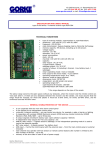
+POS -NEG
+POS -NEG
BA
Bell+
Bell-
Bell NO
Matrix
PCX/Euro 1
TEST
Risco/Gardtec
+POS -NEG
+POS -NEG
STB SPARE BT
+POS -NEG
- BAT +
DSC Range
SCB OFF
7. ALTERNATIVE TAMPER CONNECTION
HKC
BA
STB SPARE BT
TF
A
D
B
Bell +12V
HOLD OFF
BELL +12V
BHO
BELL+
AUX-
BT
Bell-
PGM2(No)
BT
B-
PGM2/STB
TR
Aux-/B-
STROBE-
TF
TAMPER
BA
STB SPARE BT
D
BELL TRIG
STB
TAMP RTN
HOLD OFF
EXT BELL-
STROBE-
BELLE
BELL-
270R TR BELLE
-STB
SCBP
PSM1
ZONE
TAMPER
EXT
BELL+ way of
SAB
HOLD
EXT
BELLINT BELL
An alternative
connecting
the Tamper
Switch
would be to connect
this to an actual zone
RTNon
the control panel programmed
as Tamper. Here are the steps to carry out this procedure:
BELLE
HO
SCBA
SAB HOLD
(with 4k7)
Negative Tamper
Return:
A linkthebetween
and Bwilloutneed
to be
¾ On the BELLE
PCB, remove
tamper switchTF
connection
and link
the TAMPER
pinsinstalled
with
the supplied
jumperA
header.
Postive Tamper
Return:
link between TF and B+ will need to be installed
the
supplied
header. on
PCX
Range
An alternative
way ofway
connecting
the
Switch
would
to connect
tojumper
actual
An alternative
of connecting
theTamper
Tamper Switch
would
be tobe
connect
this
to anthis
actual
zone
on fromzone
¾
Cut
off
the
2an
wires
the connector:
An alternative
way
of
connecting
the
thepanel
controlprogrammed
panel programmed
Tamper. Here
are
thethe
steps
to carry
this out
procedure:
the control
asas
Tamper.
Here
are
steps
to out
carry
thisTamper
procedure:Switch would
B-
B+
STRB
BELL
an
actual
input
the
panel
programmed
as
¾ On the BELLE to
PCB,
remove
the tamper
switchon
connection
and link out
TAMPER
pins with B+
PGM4
PGM5control
TR the
B¾ On the BELLE
PCB,
remove
the supplied
jumper
header.the tamper switch connection and link out the TAMPER pins with
the supplied jumpersteps
header.to
.
TF
A
0V
C
the control panel programmed as Tamper. Here are the steps to carry out this procedure:
.
B+
T
TRBELLE
S
carry out this procedure.
be to connect this
Tamper. Here are the
.
B-
LEDS LEDS
STB NO
STROBE-
7. ALTERNATIVE
TAMPER
BELL+
SCBACONNECTION
BELL
Tamper Switch:
TF
Terminal
Block
BELLE
a) On the Belle PCB, remove
theofftamper
switch
and link out the
¾ Cut
the 2 wires
from theconnection
connector:
¾ From the terminal block, take a pair wires to the zone on the control panel.
The zone
must
be programmed
TAMPER
or 24
HOUR
tamper pins with the supplied¾jumper.
Terminal
Strip the¾ insulation
of the
wire, then as
connect
the
wires
to a terminal block
¾ Cut off the 2 wires from the connector:
Block
¾ Cut off the 2 wires from the connector:
LEDS
Zone
B+
B-
B-
B+
B-
Terminal
Block
B+
Control
Panel
PIEZO
PIEZO
Zone
Zone
Zone
Page: 12
Control
Panel
RINS140-12
TEST
TEST
- BAT +
d) SCB OFF
i) Uses power from backup battery
ii)Negative Applied
ii) Uses power from 12V only
+POS -NEG
This is to change the
polarity of the trigger inputs
of both the Strobe and Bell
- BAT +
terminals
TEST
TEST
- BAT +
b) The tamper is activated
by removing the front cover
or by removing the BELLE
OFF tamper
SCBThe
from the wall.
switch can be adjusted by
carefully bending
the
SCB OFF +P
EG
OS -Nmetal
spring
c) TEST:
i)Sounder activates for 5 secs
ii)Sounder operates normally
TEST
TEST
+POS -NEG
BA
B-
B+
BA 10-14.5VDC
STB SPARE
BTnominal)
TF
(13.8V
+POS -NEG
+THE SIREN IS LOW VOLUME AND THE STROBE HAS A LOW
FLASH RATE:
-The SCB mode jumper is missing
+THE SIREN IS ONLY SOUNDING FOR 5 SECONDS.
-The test jumper is missing
+THE SIREN AND STROBE ARE NOT TRIGGERING AT ALL:
-Check the trigger selection is in the right position.
+POS -NEG
BA
B-
B+
BA
STB SPARE BT
TF
TAMPER
f) PIEZO: The Belle
incorporates
2x
LEDS
STB SPARE
BT
TF TAMPER
PIEZOs which can be
PIEZO
disconnected
while
LEDS
installing the system
so that thePIEZO
loud noise
PIEZO
will not be a distraction;
alternatively you can use
PIEZO
the Test Feature
8: Technical Specification
B+
Here is a quick troubleshooting guide to any faults that may have
occured.
B+
e) SCB = Self Contained Bell. Useful
for when there are 2 x BELLE’s on the
same system.
DO NOT TOUCH THE STROBE AS THERE IS A DANGER OF AN ELECTRIC
SHOCK. WARNING: WHEN WORKING IN CLOSE PROXIMITY IN SUBDUED
LIGHT OR DARKNESS THE STRONG LIGHT EMITTED MAY CAUSE
TEMPORARY VISION FAILURE. TAKE PRECAUTIONS!
B-
+POS -NEG
+POS -NEG
B-
PIEZO
g) STROBE: When active the strobe is powered by a 200V+ signal.
+POS -NEG
+SIREN WILL NOT TRIGGER EVEN THOUGH IT TRIGGERED IN
TEST MODE
BELLE
+POS -NEG
+POS -NEG
c) Strip the insulation of the wire, then
b) Cut
off then
theconnect
2 wires
from
¾ Strip the insulation
of the wire,
the wires
to a terminal block
-Check the voltage between B+ and B-. You should have 13V
¾ From the terminal block, take a pair wires to the zone on the
panel.
¾ If the
control
requires
an End
of Line
resistor,
follow the
shown below
¾control
Strip
the insulation
of panel
the wire,
then
connect
the
wires
to digram
a block
terminal
block(4k7 is
connect
the
wires
to
a
terminal
the
connector
¾ The zone must be programmed as TAMPER or 24 HOUR
shown only as an example):
-Check the tamper switch is closed
+POS -NEG
Page: 12 B- B+ BA STB SPARE BT TF
RINS140-12
B- B+ BA STB SPARE BT TF
-Check
the BA voltage has returned normal
EOL Resistor
B- B+ BA STB SPARE BT TF
B- B+ BA STB SPARE BT TF
Belle
2
(SAB)
Belle
1 (SAB)
¾ Strip the insulation of the wire,
then connect
the wires to a terminal block
+TAMPER
Belle 1 (SAB)
Belle 2 (SCB)
- +
-Check the case is secure and the tamper switch is closed
Power
Control
Control
Terminal
The above example shows one BELLE is connected in SAB mode and the
-Ensure the B- or B+ to TF (tamper loop) is in place for all Pyronix
Block
Panel
Panel
Supply
other in SCB mode therefore an additional power supply is not needed.
panels.
Page: 12
RINS140-12
d) From the terminal block, take a
e) If the control panel requires an end
-Check the correct tamper connections
¾ If thepair
control panel
requires
an
End
of
Line
resistor,
follow
the
digram
shown
below
(4k7
is
The
End
of
Line
resistor
must
be
inserted
at
the
bell
box.
wires to the input of the control
of line resistor, follow the diagram
If two BELLEs are connected in SCB mode, the battery back-up battery in the shown only asofan example):
When the tamper switch is activated, the control panel will sound into tamper alarm.
panel
and
program
it
as
tamper
or
24
shown
above.
The
end
of
line
resistor
control panel should be increased by 1Ah and an external power supply must
Page: 12
RINS140-12
hour
must be inserted at the bell box.
be installed to the second Belle (B+ will not need to be connected).
EOL Resistor
B-
- BAT +
i)Positive Applied
SCB OFF +POS -NEG
TAMPER
TF TAMPER
Tamper
B
BELL
BT
.
6: Alternative Tamper
Connection
7:TAMPER
Quick
Reference For Faults
¾ On the BELLE
PCB, remove the tamper switch connection and link out the
pins with
Control Panel
Bell
Trigger
A
0V
STB
NOTE: If powered up with tamper switch the sounder will not sound and the triggering
inputsway
will
be inoperable
until
thewould
tamper
is closed.
An alternative
of connecting
the Tamper
Switch
be toswitch
connect this
to an actual zone on
Wired to
control panel
5: Wiring Two Belles in Series
Strobe
Trigger
TAMPER
D
12V
Tamper Switch:
Menvier
Tamper Switch:
B+
PGM1(No)
PGM1/BELL
7. ALTERNATIVE TAMPER CONNECTION
Texecom
7. ALTERNATIVE TAMPER CONNECTION
B-
AuxAux-/B-
ADE
Scantronic
GE
Tamper Switch:
Aux+
Aux+/B+
- BAT +
4: Printed Circuit Board Descriptions
a) +POS -NEG:SCB OFF
For electrical products sold
within the EuropeanCommunity.
At the end of the electrical
products useful life, it should
not be disposed of with
household waste. Please
recycle where facilites exist.
Check with your Local Authority
or retailer for recycling
advice in your country. When
disposing of the product the
batteries must be removed
and
disposed of seperately
LEDS
in accordance with the local
PIEZO
LEDS regulations.
G OS -NEG
+POS -NE+P
PIEZO
BA
- BAT +
B-
- BAT +
SCB OFF SCB OFF
TEST
PIEZO
+POS -NEG
LEDS
B+
TEST
End of line
TF resistor
B+
Sterling 10
B-
- BAT +
+POS -NEG
Bell
Bell
Trigger
Tamper
Strobe
- BAT +
Trigger
3a) Wiring the bell tamper with an EOL resistor
BELLE
(iv) Take off the printed circuit board
cover and start the connections as
shown on the next step.
- BAT-+BAT +
TF
SCB OFF
STB SPARE BT
- BAT +
BA
SCB OFF
0v +12v
TAMPER
Belle Terminals:
B- = 0V
B+ = +12V
BA = Bell Activate (Trigger)
STB = Strobe Activate (Trigger)
BT = Bell Tamper
TF = Tamper Feed (Put to 0V
(Negative tamper return) or 12V
(Positive tamper return) if another
bell is not used)
TF
Control
Panel
SPARE BT
Screw the top left screw into the plug
leaving enough screw showing to hang
the Belle from.
- BAT +
- BAT +
TF
- BAT +
- BAT +
STB SPARE BT
Connections
(iii) Route the alarm cable through the
wall, and mount the Belle on the wall
from the affixed screw.
B+
BA STB
BA SPARE
STB SPARE
BT TFBT TAMPER
TF TAMPER
B- B+
B- B+
BA STB
BA SPARE
STB SPARE
BT TF
BT
BA
Panels
STB
BA SPARE
STB SPARE
BT TF
BT
B+
i)The Belle should be mounted on a flat
surface in a high visibility area, and the
cables should be routed away from the
mains supply.
ii) Use the template on the Belle
packaging to mark the position of 4
mounting holes, and drill the holes and
use the wall plugs provided.
Terminal Connections for other Control Panels
Belle
B-
d) Status LEDs
B+
B-
3
c) Printed
Circuit Board
Cover
TF
B- B+
B- B+
BA
3: Connections
g) Cable Entry
B-
RINS140-16
f) Mounting Holes
b) Battery
B+
BA STB
BA SPARE
STB SPARE
BT TFBT
EN50131-4:2009
e) Front and
Rear Tamper
a) Piezos
B+
B-
Installation Guide
2
POWER
Isolate from the power supply until the installation is complete. The B+
terminal at the control panel should be the last connection made.
200 VOLT
Do not touch the strobe light. There is a danger of electric shock.
BATTERY
Any battery left connected for more than 24 hours, without a power supply
connected will go into deep discharge, and may not recover.
SHOCK
Mount the sounder away from the public, especially in enclosed areas such
as alleyways and corridors, in order to reduce any shock hazard caused by
the start of a sudden loud noise.
WARRANTY
This product is sold subject to our standard warranty conditions and is
warranted against defects in workmanship for a period of one year. In the
interest of continuing improvement of quality, customer care and design,
Pyronix Ltd reserve the right to amend specifications without giving prior
notice.
CUSTOMER SUPPORT
Tel: +44(0)845 6434 999 (local rate) or +44(0)1709 535225
Opening Hours: 8:00am - 6:30pm.
Email: [email protected]
Website: www.pyronix.com
B-
2x
2: Installation of the Belle
B+
External Sounder
+
P
PIE
PIE
1: Important Notes
B-
LEDS
BELLE
STB SPARE BT
TF
PIEZO
OPERATING TEMPERATURE
SIREN AND STROBE OUTPUT
Reverse polarity protected
SCB Mode: 108dBA @ 1m
PIEZO
Maximum Peak: 118dBA @1m
Flash rate: 120/min typical (30/min SCB mode)
CURRENT CONSUMPTION
Tube Size: 3 Watt
Standby (alt.flashing): 65mA typical
(+10mA for backup battery)
BACK UP BATTERY
Strobe only: 175mA typical
280mAh 7.2V NiCad (Included)
Siren only: 230mA typical
30min continuous use (Siren and Strobe)
Siren and Strobe: 480mA typical
SCB mode: 70mA typical
SIREN CUT OFF TIMER
Test: ≤ 5 seconds
DIMENSIONS & WEIGHT
Normal: ≤ 15 minutes
Dimensions: 334mm x 235mm x 55mm
Weight: 1.05kg
ENVIRONMENT
Base: 3mm Polycarbonate polished
Operating Temperature: -30°C to 50°C
Lid: 3mm Polycarbonate polished
Storage Temperature: -40°C to 60°C
This product is suitable for use in systems designed to comply with PD6662:2010 at
Security Grade 2 and Environmental Class 4
Sirène d’alarme extérieure Guide d’installation
1. Remarques importantes ALIMENTATION Ne pas connecter au secteur tant que l’installation n’est pas terminée. Le connecteur B+ sur la centrale d’alarme doit être la dernière connexion à faire. 200 VOLTS Ne touchez pas à la lampe flash. Il y a risque
de choc électrique. BATTERIE La batterie sera endommagée par décharge de longue durée si elle reste connectée plus que 24
heures sans la présence du secteur. CHOCS Monter la sirène loin des lieux publics, surtout pas dans les locaux fermés et les
couloirs, pour réduire le risque de choc dû au déclenchement du son aigu. GARANTIE Ce produit est soumis à nos conditions
standard de garantie. Il est garanti contre les défauts de fabrication pour une période de 12 mois. Dans le but d’améliorer la
qualité, le service client et la conception, Pyronix LTD se réserve le droit de modifier les spécifications sans notification.
Sirena Esterna Guida all’Installazione
1. Note Importanti ALIMENTAZIONE Non alimentare la sirena fino alla conclusione dell’installazione. Collegare il morsetto B+
della centrale per ultimo. 200 VOLT Non toccare la lampadine del lampeggiante. C’è il rischio di shock elettrico. BATTERIA
Se la batteria rimane connessa più di 24h in assenza della tensione di rete, essa rischia di scaricarsi completamente e di non
ricaricarsi più. SHOCK Installare la sirena lontano dal pubblico, all’area aperta in modo da ridurre il pericolo di shock causato
dall’impatto iniziale del suo rumore. GARANZIA Questo prodotto viene venduto alle condizioni del nostro standard di garanzia
ed è garantito contro i difetti di fabbrica per un periodo di un anno. Nell’ottica di un continuo miglioramento della qualità, della
cura del cliente e dell’immagine, Pyronix Ltd si riserva il diritto di modificare le specifiche senza preavviso.
Syrena zewnętrzna Instrukcja podłączenia
2. Installation de la sirène: a) haut-parleurs piézoélectriques, b) Batterie, c) Couvercle de la carte électronique, d) diode LED
d’état, e) Contact de fermeture du boîtier avant et arrière, i) La sirène doit être installé sur une surface plate, dans un endroit
bien visible, et le chemin des câbles doit être loin des lignes du secteur. f) Trous de fixation, ii) Utiliser la feuille patron pour
marquer les 4 trous de fixation, percer les trous et utiliser les vis fournies. Visser la vis du côté haut gauche juste pour permettre
de fixer la sirène, g) Entrée de câbles. iii) Acheminer le câble d’alarme à travers le mur, et monter la sirène sur le mur par la vis
de fixation. iv) Enlever le couvercle de la carte électronique et réaliser les connexions telles que décrites dans l’étape suivante.
2) Installazione della Belle
a)Piezo b)Batteria, c)Protezione del circuito stampato, d)Led di Stato, e)Tamper anti-apertura/anti-rimozione, i)La Belle deve
essere installata su una superficie piana e ben in vista, i suoi cavi devono passare lontano da quelli di alta tensione, f)Fori di
fissaggio, ii)Usare la dima sulla scatola per segnare la posizione dei 4 fori di fissaggio, forare e usare i tasselli in dotazione. Avvitare la vite nel tassello alto sinistro lasciando una parte di essa per agganciarvi la Belle. g)Entrata dei cavi (iii)Passare il cavo
di allarme e fissare la Belle al muro mediante la vite avvitata in precedenza. (iv) Rimuovere il coperchio di protezione del circuito
stampato ed eseguire le connessioni come mostrato nelle tappe successive.
2. Instalacja syreny a) Głośniki, b) Akumulator, c) Pokrywa płyty elektronicznej, d) Diody LED, e) Wyłącznik sabotażowy, i)
Syrena powinna być zainstalowana na równiej ścianie w widocznym miejscu a przewody poprowadzone z dala od zasilania
sieciowego. f) otwory montażowe ii) Użyj szablonu z opakowania, w celu zaznaczenia miejsca na otwory. Wywierć w ścianie
4 otwory i umieść w nich kołki montażowe. Wkręć lewą górną śrubę na tyle, aby zawiesić tymczasowo syrenę. g) Wprowadź
przewody (iii) Przeprowadź przewody przez ścianę i zamocuj syrenę, wkręcając pozostałe śruby. (iv) Otwórz pokrywę płyty
drukowanej I podłącz przewody, zgodnie z następnym rysunkiem.
3. Connexions: Les bornes de la sirène : B- = 0V, B+ = 12V, BA = Activation de la sirène (déclenchement), STB = Activation de
la lumière stroboscopique (déclenchement), BT = Autoprotection de la sirène, TF = Alimentation Autoprotection (Connectez au
0V (retour autoprotection négatif) ou 12V (retour autoprotection positif) si aucune autre sirène n’est installée) NOTE : Si elle est
alimentée via l’interrupteur de l’autoprotection, la sirène ne sera active que si cet interrupteur est fermé.
CHN
4. CARTE ÉLECTRONIQUE: a) +POS –NEG : i) Plus appliqué ii) Moins appliqué C’est pour changer la polarité des entrées de
déclenchement sur les bornes du flash et sirène. b) L’autoprotection est activée en arrachant la sirène du mur ou en enlevant
le couvercle frontal. L’interrupteur de l’autoprotection peut être ajusté en déformant le ressort métallique. c) TEST : i) La sirène
fonctionne pendant 5 secondes ii) La sirène fonctionne normalement d)SCB OFF i) alimentée de la batterie de secours et par
12 V ii) alimentée seulement par 12 V e) SCB = Sirène Auto Incluse. Utile lorsqu’il y a deux sirènes dans le même système.f)
PIEZO : La sirène intègre deux transducteurs piézoélectriques qui peuvent être déconnectés au moment de l’installation pour
éviter le bruit en cas de déclenchement. Autrement, vous pouvez utiliser l’option « Test » g) FLASH : Quand il est activé, le
flash est alimenté par 220 V. NE PAS TOUCHER A LA LUMIERE STROBOSCOPIQUE : DANGER DE CHOC ELECTRIQUE.
LORSQUE VOUS TRAVAILLEZ DANS UN MILIEU NON SUFFISAMMENT ECLAIRE, LA LUMIERE FORTE DU FLASH PEUT
CAUSER DES TROUBLES TEMPORAIRES DE LA VISION. PRENEZ VOS PRECAUTIONS !
FRA
5. Câblage de 2 sirènes en série: L’exemple ci-dessus montre une sirène connectée en mode SAB et une autre connectée en
mode SCB. Pour cela, une alimentation additionnelle n’est pas nécessaire. Si deux sirènes sont connectées en mode SCB,
la batterie de secours de la centrale d’alarme doit avoir 1Ah supplémentaire et la deuxième sirène doit sera obligatoirement
connectée à une alimentation externe (B+ peut ne pas être connecté)
3. Collegamenti
Morsettiera: B- = 0V, B+ = +12V, BA = Tromba, STB = Strobo, BT = Tamper Sirena, TF = Ritorno del Tamper (Collegare a 0V)
o 12V( Ritorno Positivo del Tamper) se non connesso a un’altra sirena NOTA: Se la sirena viene alimentata con tamper aperto,
essa non suonerà. I suoi ingressi di attivazione rimarranno esclusi fino a quando il tamper verrà chiuso.
ITA
4. CIRCUITO STAMPATO a) + POS – NEG: i)Positivo a dare ii)Negativo a dare Serve per cambiare la polarità di attivazione
di entrambi la sirena e lo strobo. b) Il tamper viene attivato aprendo il coperchio o rimuovendo la sirena dal muro. Esso può
essere regolato piegando delicatamente la levetta metallica. c) TEST: i) La sirena si attiva per 5secondi ii) La sirena funziona
normalmente d) SCB OFF i)Usa l’alimentazione dalla batteria tampone ii)Usa solo l’alimentazione da 12V e)SCB = Sirena
Autoalimentata(Self Contained Bell). Utilissimo se vengono installate 2 sirene in un sistema. f) PIEZO: La Belle contiene 2 Piezo
che possono essere scollegate per evitare l’attivazione durante l’installazione del sistema. Altrimenti si può utilizzare la funzione
di test. g) STROBO: Quando la Belle è attiva, lo strobo viene alimentato con un segnale di 200V+ NON TOCCARE MAI LO
STROBO PERCHE’ SI RISCHIA UNO SHOCK ELETTRICO.ATTENZIONE: SE STATE LAVORANDO IN UN AMBIENTE
CHIUSO CON POCCA ILLUMINAZIONE O AL BUIO, IL FLASH EMESSO POTREBBE CAUSARVI UN ABBASSAMENTO
DELLA VISTA. PRENDERE QUINDI PRECAUZIONE!
5. Collegamento di 2 Belle in serie L’esempio sopra mostra una sirena connessa in modalità SAB e l’altra in SCB per non utilizzare un’alimentazione secondaria. Se le 2 BELLE vengono connesse in modalità SCB, sarà necessario aumentare la capacità
della batteria della centrale di 1Ah e installare un’alimentazione ausiliaria per la seconda BELLE (in questo caso B+ non va
collegato in centrale).
6. Connexion alternative de l’autoprotection: Une autre méthode pour connecter l’interrupteur de l’autoprotection est de le relier
à une zone de la centrale programmée comme zone d’autoprotection. Voici les étapes pour réaliser cette procédure.
a) Sur la carte électronique de la sirène, enlever l’interrupteur d’autoprotection et relier les pins par le jumper fourni.
b) Couper les deux fils du connecteur c) dénuder les deux fils et connecter les à une douille. d) à partir de la douille, prenez
deux fils à une zone de la centrale d’alarme et programmez la comme zone autoprotection ou 24 heures c) Si la centrale
d’alarme exige une résistance terminale, suivez la figure ci-dessus. La résistance est à insérer dans le boîtier de la sirène.
6. Altro tipo di Connessione del Tamper: Il Tamper può esser anche collegato direttamente a un ingresso della centrale programmato come tamper. Vedi come collegare il Tamper nella la procedura sotto: a) Rimuovere il connettore del Tamper dalla scheda
della Belle e chiudere i pin Tamper con il ponticello in dotazione. b) Tagliare il connettore del tamper c) Giuntare i 2 fili del
tamper con quelli provenienti dalla centrale. d) Collegare i 2 fili provenienti dal tamper a un ingresso della centrale programmato
come tamper o 24h.e) Se la centrale richiede una resistenza di fine linea, seguire lo schema nella figura sopra. La resistenza va
collegata sul campo cioè alla belle.
7. Référence pratique pour les pannes: Voici un guide de dépannage rapide pour toutes les pannes qui peuvent survenir.
+ LE VOLUME DE LA SIRENE EST BAS ET LE FLASH EST LENT - Le jumper du mode SCB est enlevé + LA SIRENE
RETENTIT POUR 5 SECONDES SEULEMENT - Le jumper de TEST est enlevé + LA SIRENE ET LE FLASH NE FONCTIONNENT PAS - Vérifier que la sélection de déclenchement est à la position droite + LA SIRENE NE SE DECLENCHE
PAS MALGRE QU’ELLE MARCHE EN MODE TEST - Vérifier la tension entre B+ et B-. Vous devez avoir 13V - Vérifier
que la tension BA est retournée à la normale + AUTOPROTECTION - Vérifier que le boîtier est intact est que l’interrupteur
d’autoprotection est fermé. - Vérifier que B- ou B+ vers TF (Boucle d’autoprotection) est en place pour toutes les centrales
Pyronix - Vérifier que les connexions d’autoprotection sont correctes.
7. Guida di riferimento per i guasti
Di seguito viene proposta una guida per la ricerca veloce dei guasti.+ IL VOLUME DELLA SIRENA è BASSO E LO STROBBO
LAMPEGGIA LENTAMENTE: -Manca il ponticello della modalità SCB +LA SIRENA SUONA SOLO PER 5 SECONDI
-Il ponticello di Test è inserito +NON FUNZIONA NE’ LA SIRENA NE’ IL LAMPEGGIANTE: -Controllare che sia selezionata la
polarità di attivazione corretta. +LA SIRENA NON SUONA ANCHE SE VIENE ATTIVATA IN MODALITA’ TEST. -Controllare la
tensione tra B+ e B-. Devono esserci 13V -Controllare che il tamper sia chiuso -Controllare che la tensione al BA sia tornata
normale -Verificare che il coperchio e il tamper siano ben chiusi -Accertasi che B- o B+ connesso al TF sia a posto per tutte le
centrali della Pyronix -Controllare che le connessioni del tamper siano eseguite correttamente.
8. Specifiche Tecniche
8 : Caractéristiques Techniques
1. Ważne informacje ZASILANIE Nie podłączaj zasilania dopóki wszystkie podłączenia nie zostaną wykonane. Zacisk B+
powinien być podłączony z centralą jako ostatni. NAPIĘCIE 200V Nie dotykaj lampy stroboskopowej. Zagrożenie porażenia
prądem elektrycznym. AKUMULATOR Nie zostawiaj podłączonego akumulatora syreny na dłużej niż 24 godziny bez zasilania
zewnętrznego. Może zostać uszkodzony. SZOK DŹWIĘKOWY Nie instaluj syreny w zamkniętych obszarach, takich jak wąskie
przejścia, korytarze aby uniknąć szoku, wywołanego głośnym dźwiękiem. GWARANCJA Produkt jest objęty standardowym
okresem gwarancji i zapewnia prawidłowe działanie przez 1 roku. W tym okresie bezpłatnie będą usuwane usterki powstałe z
winy producenta. Pyronix Ltd zastrzega sobie prawo zmian specyfikacji bez wcześniejszego uprzedzenia.
3. Połączenia Zaciski syreny: B-=masa, B+=+12V, BA = Sterowanie syreny, STB = Sterowanie lampy, BT=Sabotaż syreny,
TF =Zacisk wspólny wyłącznika sabotażowego (może być podłączony do masy, zasilania =12V lub działać bezpotencjałowo
wspólnie z zaciskiem BT. ZAUWAŻ: Po podłączeniu zasilania, sterowanie syreną będzie możliwe dopiero po zamknięciu
wyłącznika sabotażowego
4. PŁYTA ELEKTRONICZNA SYRENY a)+POS –NEG: i) Wyzwalanie plusem ii) Sterowanie masą Zworka ta służy do wyboru
sposobu wyzwalania sygnalizacji optycznej oraz akustycznej. b) Alarm sabotażowy jest aktywowany w momencie zdjęcia
przedniej pokrywy lub oderwanie od ściany. Wyłącznik sabotażowy może być regulowany przez ostrożne wyginanie sprężynki
wyłącznika. c) TEST: i) Syrena jest aktywowana na 5 minut ii) Syrena jest aktywowana normalnie d) SCB OFF i) Używane
zasilanie z baterii ii)Używane tylko zasilanie zewnętrzne e) SCB = Syrena współdzielona. Używany, gdy do jednego systemu
są podłączone dwie syreny. f) PIEZO; Gniazda do podłączenia głośników. Mogą być odłączone podczas instalacji, aby nie
generować niepotrzebnego hałasu. Zamiennie można również użyć funkcji TEST. g) LAMPA STROBOSKOPOWA: Zasilana jest
napięciem 200V. NIE DOTYKAĆ LAMPY PODCZAS PRACY, GROZI TO PORAŻENIEM PRĄDEM ELEKTRYCZNYM. PODCZAS ZAMYKANIA OBUDOWY, LAMPA MOŻE WYEMITOWAĆ KRÓTKIE BŁYŚNIĘCIE, CO W ZACIEMNIONYM MIEJSCU
MOŻE WYWOŁAĆ NAGŁE OŚLEPIENIE.
POL
5. Szeregowe podłączenie 2 syren Poniższy przykład przedstawia jedną syrenę podłączoną w trybie SAB a inną w trybie
SCB, dlatego dodatkowy zasilacz nie jest wymagany.Jeżeli dwie syreny BELLE będą podłączone w trybie SCB, pojemność
akumulatora podtrzymującego zostanie zwiększona o 1Ah i powinien być podłączony dodatkowy zasilacz do drugiej syreny (B+
nie wymaga podłączenia).
6. Alternatywne podłączenie sabotażu Ochrona sabotażowa syreny może być podłączona do linii alarmowej centrali, zaprogramowanej jako SABOTAŻ. Poniżej opisano procedurę podłączenia a) Odłącz wyłącznik sabotażowy od płyty elektronicznej
oraz zdejmij zworkę opisaną jako TAMPER b) Odetnij złącze od przewodu wyłącznika c) Odizoluj przewody i podłącz do
kostki połączeniowej d) Do drugiej strony kostki połączeniowej podłącz przewody do linii alarmowej, zaprogramowanej jako
Sabotażowa lub 24-godzinna e) Jeżeli centrala wymaga rezystora zakończenia linii, należy go podłączyć wewnątrz obudowy
syreny, jak przedstawiono na rysunku.
7. Rozwiązywanie problemów Przedstawiono tutaj typowe problemy, mogące pojawić się podczas instalacji. +SYRENA MA
MAŁĄ GŁOŚNOŚĆ I LAMPA ŚWIECI SIĘ BARDZO SŁABO. - Syrena pracuje w trybie SCB +SYRENA ZAŁĄCZA SIĘ TYLKO
NA 5 SEKUND.- Zdjęta zwora TEST +BRAK SYGNALIZACJI OPTYCZNE I AKUSTYCZNEJ: -Sprawdź ustawienia wyzwalania
syreny +SYRENA NIE ZAŁĄCZA SIĘ PODCZAS WYZWALANIA W TRYNIE TESTU -Sprawdź napięcie na zaciskach B+ i B-.
Powinno być ok. 13V -Sprawdź, czy wyłącznik sabotażu jest zamknięty -Sprawdź napięcie akumulatora +SABOTAŻ SYRENY
Sprawdź, czy obudowa syreny jest zamknięta -Upewnij się, czy zacisk TF jest prawidłowo podłączony. -Sprawdź poprawność
podłączenia obwodu antysabotażowego.
8: Specyfikacje techniczne
Sirene Exterior Manual de Instalação
Sirena de exterior Guía de instalación
Harici İskandil Kurulum kılavuzu
1. Notas Importantes ALIMENTAÇÃO Isolar a alimentação até que a instalação esteja concluída. No painel de controlo o
terminal B+ deverá ser o último a ser conectado. 200 V Não tocar na luz de strobe. Existe perigo de choque eléctrico.
BATERIA Qualquer bateria que esteja ligada mais de 24 horas, sem estar em carga, entrará em descarga completa o que
poderá inviabilizar a sua reutilização. CHOQUE Instalar a sirene distante do público, especialmente em locais fechados ou
corredores, para reduzir qualquer tipo de danos provocados pelo arranque inesperado do sinal sonoro da sirene. GARANTIA
Este produto está sujeito às nossas condições de garantia padrão contra defeitos de Fabrico por um período de um ano. Com o
intuito de melhorar continuamente a qualidade, apoio ao cliente e concepção dos seus produtos, a Pyronix reserva-se no direito
de alterar as especificações sem aviso prévio.
1. Notas importantes ALIMENTACIÓN Aislar de la fuente de alimentación hasta completar la instalación. El terminal B+ debería
ser el ultimo en ser conectado. 200 VOLTIOS No tocar la luz de Strobo. Existe peligro de choque eléctrico.
BATERÍA Cualquier batería conectada por más de 24 horas sin alimentación entrará en descarga absoluta y puede que no se
recupere. SCHOCK Evitar provocar shock auditivo. Installe la sirena alejado del público, evitar especialmente areas cerradas
como corredores GARANTÍA Este producto se ofrece con garantía de 1 año contra defecto de fabricación. Esta garantía
está sujeta a los terminos y condiciones establecidos por Pyronix Limited. En interés de continuar el constante desarrollo del
producto, Pyronix Limited se reserva el derecho de alterar especificaciones técnicas sin ofrecer aviso con antelación.
1. Önemli Notlar GÜÇ Yalıtım tamamlanıncaya kadar güç kaynağından izole edin. Kontrol panelindeki B+ terminali son
bağlantısı yapılmış şekilde olmalıdır. 200 VOLT Stroboskop ışığına dokunmayın. Elektrik çarpması tehlikesi bulunmaktadır.
2. Instalación de la sirena Belle a) Piezo’s, b) Batería, c) Tapa protectora PCB, d) LED´s de estado, e) Tamper frontal y trasero.
i) Belle debería ser montada en una superficie plana en un area de gran visibilidad y los cables debería estár distanciados de la
fuente de alimentación. f) Agujeros de montaje ii) Use el dibujo en la caja de la sirena para ayudar a posicionar los 4 agujeros
de montaje en la pared. Cuando atornille, dejar espacio en los tornillos para colgar la Belle g) Entrada del cable
(iii) Pasar cable a través de la pared y colgar la sirena de los tornillos (iv) Retirar la tapa protectora de la PCB y comenzar las
conexiones como se ilustra en el siguiente paso.
2. Instalação da sirene Belle a) Piezo’s, b) Bateria c) Cobertura da Placa de Circuito Impresso, d) Estado dos LEDs, e) Tamper
Frontal e Traseiro i) A Belle deve ser instalada numa superfície plana numa área de grande visibilidade e os cabos deverão
estar afastados da alimentação principal. f) Pontos de Fixação ii) Usar o modelo que acompanha a Belle para marcar os 4
pontos de fixação, faça os buracos na parede e, de seguida, aplique as fichas de parede fornecidas bem como os parafusos
para que seja possível aplicar a Belle.g) Entrada de cabos (iii) encaminhar o cabo de alarme pela parede, e fixar a Belle na
parede usando os parafusos aplicados anteriormente. (iv) Retirar a cobertura da placa de circuito impresso e iniciar as ligações
como se explica no próximo passo.
3. Conexiones Terminales Belle: B- = 0V, B+ = +12V, BA = Disparo sirena, STB = Disparo flash, BT = Tamper sirena, TF =
Retorno Tamper (para retorno negativo conectar a 0V, para retorno positivo conectar a 12V) si otra sirena Belle no es usada
3. Ligações Terminais Sirene Belle: B- = 0V, B+ = +12V, BA = Activa Sirene (Disparo), STB = Active Strobe (Disparo), BT =
Tamper Sirene, TF = Retorno de Tamper (Se não for usada outra sirene aplicar 0V (retorno de tamper negativo) ou 12V (retorno
de tamper positivo)) NOTE: Ao alimentar a sirene com o comutador de tamper aberto a sirene não toca e as entradas de
disparo ficarão inactivas até que o comutador de tamper seja fechado.
4. PLACA DE CIRCUITO IMPRESSO a) +POS -NEG: i)Aplicação de Positivo ii)Aplicação de Negativo Para alterar a polaridade
das entradas de disparo de ambos os terminais. b) O tamper é activado removendo a cobertura frontal ou removendo a sirene
Belle da parede. O comutador de tamper pode ser ajustado dobrando cuidadosamente a mola metálica c) TESTE: i) Sirene
activa durante 5 seg. ii) Sirene opera normalmente d) SCB OFF i) Utiliza alimentação fornecida pelas baterias internas. ii)Utiliza
apenas alimentação fornecida pelos 12V e) SCB - Útil para situações em que se instala duas sirenes num sistema. f) PIEZO:
A sirene inclui 2 x PIEZOS que podem ser desligados quando se instala o sistema para que o sinal sonoro não seja uma
distracção; em alternativa pode-se usar o modo de TESTE. g) STROBE: Quando activo é alimentado por um sinal de 200V+.
NÃO TOCAR NO STROBE PORQUE EXISTE PERIGO DE CHOQUE ELECTRICO.AVISO: AO TRABALHAR NA PROXIMIDADE DA SIRENE EM CONDIÇÕES DE FRACA LUMINOSIDADE OU NA TOTAL AUSÊNCIA DE LUZ A FORTE LUZ EMITIDA
PODE CAUSAR CEGUEIRA TEMPORÁRIA. TOMAR PRECAUÇÕES!
PRT
5. Ligar 2 Belles em Série O exemplo mostra uma BELLE conectada no modo SAB e outra no modo SCB, sendo assim não é
necessário recorrer a alimentação adicional. Se duas BELLEs forem conectadas no modo SCB, a bateria no painel de controlo
deve ter mais 1AH de capacidade e será necessário instalar uma fonte de alimentação adicional para a segunda BELLE (neste
caso não é necessário conectar o terminal B+ à segunda BELLE)
6. Ligação Alternativa p/ o Tamper É possível ligar o comutador de tamper directamente a uma entrada do painel de controlo
programada como Tamper. Os passos seguintes descrevem o procedimento a utilizar nesta situação: a) Na placa da BELLE,
remover a ligação do comutador de tamper e ligar os pinos de tamper com o jumper fornecido. b) Cortar os 2 fios do conector.
c) Retirar o isolamento do cabo e em seguida conectar os fios ao bloco de terminais da sirene.d) A partir do bloco de terminais
usar um par de fios para ligar ao painel de controlo e programar a entrada como tamper ou 24H. e) Se o painel de controlo
requer uma resistência final de linha (RFL), seguir a indicação da figura. A RFL deverá ser instalada na sirene.
NOTA: Si se alimenta la sirena con el switch de tamper abierto, la sirena no sonará y las entradas de disparo no operarán hasta
que el switch del tamper se cierre.
RUS
4. PLACA DE CIRCUITO IMPRESO a) +POS -NEG: i)Positiv Aplicado ii)Negativo Aplicado Para cambiar la polaridad de la
entrada de disparo de la alarma y del flash de la sirena b) El tamper se activa cuando se retira la tapa o arrancando la sirena
de la pared. Para paredes con desnivel ajustar el contacto del tamper abriendo o cerrando el muelle palanca. c) TEST: i)Sirena
se activa por 5 segundos ii)Sirena opera normalmente d) SCB OFF i)Usa alimentación de la batería ii)Usa 12V alimentación
solamente e) SCB = Sirena autocontenida. Útil en la connexion de 2 x Belle al mismo panel. f) PIEZO: Belle tiene 2 x PIEZOs
que pueden ser desconectados mientras se realiza la instalación; alternativamente puede usar el TEST g) FLASH: Cuando se
active el flash produce una señal de 200V+. NO TOCAR EL FLASH, HAY RIESGO DE SHOCK ELECTRICO. ADVERTENCIA:
CUANDO SE ENCUENTRE EN CONDICIONES DE BAJA LUMINOSIDAD O EN LA OSCURIDAD EL FLASH PUEDE CAUSAR
CEGUERA TEMPORAL. ¡TOME PRECAUCIONES!
ESP
5. Conexión de 2 Sirenas Belle en serie El ejemplo arriba muestra una sirena BELLE conectada en modo SAB y la otra en
modo SCB. Con esta conexión no es necesario una fuente de alimentación adicional. Si 2 sirenas BELLE están conectadas en
modo SCB, la batería de backup del panel debería incrementarse en capacidad al menos en 1 Ah y una fuente de alimentación
adicional debería ser conectada a la segunda sirena Belle (B+ no necesita ser cableado).
6. Conexión de tamper alternativa: Otra alternative de conectar el switch de tamper sería cablear éste a una entrada del panel
y programarla como tamper. Siga los pasos siguientes a continuación: a) En la placa de la Belle, retirar el cable del switch the
tamper y cortocircuitar los pines con el jumper que se suministra.b) Cortar los dos cables del conector
c) Añadir la extension de cable necesaria (aislar la unión con estaño y cubrir) para llevar el cable a una de las entradas de
zona del panel. d) Programar la zona del panel como tamper o 24 horas e) Si el panel exige Resistencia EOL, siga el diagrama
indicado para conectar la Resistencia EOL en los terminals de la sirena Belle.
7. Rápida Referência de Falhas Descreve-se em seguida um pequeno guia com soluções para algumas das falhas mais
frequentes: +O VOLUME DA SIRENE É BAIXO E O STROBE PISCA LENTAMENTE: -Falta colocar o jumper do modo SCB.
+A SIRENE SÓ TOCA DURANTE 5 SEG.-Falta colocar o jumper de teste. +A SIRENE E O STROBE NÃO ACTUAM:
-Verificar se a selecção de activação está correcta +A SIRENE NÃO TOCA, MAS TOCA EM MODO DE TESTE: -Verificar a
tensão entre B+ e B- (deverá ter 13VDC). -Verificar se o comutador de tamper está fechado -Verificar se a tensão BA regressou
ao normal +TAMPER -Verificar se a caixa está segura e se o comutador de tamper está fechado. -Garantir que B- ou B+ ao TF
(tamper loop) estão correctamente ligados ao painel de controlo. -Verificar as ligações correctas do tamper
7. Guía rápida de fallas: Lista de los problemas más communes con los que se puede encontrar:.+LA SIRENA TIENE UN
VOLÚMEN BAJO Y PARPADEO DE FLASH LENTO: -El jumper de los pines de modo SCB no está puesto. +LA SIRENA SOLO
SUENA POR 5 SEGUNDOS. -El jumper de Test no está conectado +LA SIRENA Y EL FLASH NO SE DISPARAN: -Verificar
que la selección del disparo se encuentra en la posición correcta. +SIRENA NO SE DISPARA AUNQUE SE DISPARÓ EN
MODO DE TEST -Verificar voltaje entre B+ y B-, comprobar que tiene 13V -Comprobar que el switch de tamper está cerrado.
-Comprobar que el voltaje en BA ha vuelto a normal.+TAMPER -Comprobar que el switch de tamper está cerrado, -Compruebe
las conexiones a B- y B+ a TF (lazo tamper) están realizadas correctamente. -Comprobar la conexión de los tampers.
8: Especificações Técnicas
8: Especificaciones Técnicas
BATARYA Bir güç kaynağı bağlanmadan herhangi bir bataryanın 24 saatten fazla bağlı bırakılması durumunda tamamen
boşalacaktır ve kurtarılması mümkün olmayabilir. ŞOK Ani yüksek sesli gürültünün başlaması ile herhangi bir şok tehlikesini
düşürmek amacıyla İskandili özellikle dar yollar ve koridorlar gibi kapalı alanlarda, kamusal alandan uzakta monte edin.
GARANTİ Bu ürün bir yıllık süre için işçilikteki hataları karşı garanti altına alınmıştır ve bizim standart garanti koşullarımıza
bağlı olarak satılmıştır. Devam eden kalite, müşteri hizmeti ve tasarım geliştirme ile ilgili olarak Pyronix Ltd bildirim olmaksızın
özellikleri değiştirme hakkını saklı tutmaktadır.
2. Belle nin Yüklenmesi a) Basınçlar, b) Batarya, c) Baskılı Devre Levhası Kapağı, d) Durum LED leri, e) Ön ve Arka Tamper
i)Belle bir yüksek derecede görülebilir alanda düz bir yüzey üzerinde monte edilmelidir ve kablolar şebeke güç kaynağından
uzağa çekilmelidir. f) montaj delikleri ii) Bellek paketi üzerindeki şablonu kullanarak 4 montaj deliğini işaretleyin ve delikleri açın
ve verilen duvar eklentilerini kullanın. Belle den asıldığını göstermeye yetecek kadar üst sol vidayı eklentide vidalayın.
g) Kablo Girişi (iii) Alarm kablosunu duvardan geçirin ve belle yi sabitlenmiş vidadan duvar üzerinde monte edin. (iv) Baskılı
devre levhası kapağını çıkartın ve sonraki adımda gösterildiği gibi bağlantıları başlatın
3. Bağlantılar Belle Terminalleri: B- = 0V, B+ = +12V, BA = Zill Aktif (Başlatıcı), STB = Stroboskop Aktif (Başlatıcı), BT = Zil
Tamperi, TF = Tamper Beslemesi (Eğer başka bir kullanılmamış ise 0V a (Negatif tamper dönüşü) veya 12V (Pozitif tamper
dönüşü) ye koyun).NOT: Eğer tamper switchi ile güç verilmiş ise iskandil ses vermeyecektir ve başlatma girişleri tamper switchi
kapatılıncaya kadar çalışır durumda olmayacaktır.
4. BASKILI DEVRE LEVHASI a) +POS -NEG: i)Pozitif Uygulanmış ii)Negatif Uygulanmış Bu Stroboskop ve Zil terminallerinin
ikisinin başlatıcı girişlerinin polaritesini değiştirmek içindir. b) Tamper ön kapağın çıkartılması ile veya BELLE nin duvardan
çıkartılması ile aktifleşmiştir. Tamper switchi metal yayı dikkatli şekilde bükerek ayarlanabilir. c) TEST: i)İskandil 5 saniye için
aktiftir ii) İskandil normalde çalışır d) SCB OFF i)Yedek bataryadan güç kullanır ii)sadece 12V güç kullanır e) SCB = Kendinden
Dahil Edilmiş Zil. Aynı sistemde 2 x BELLE olduğu zaman kullanışlıdır f) BASINÇ: Belle sistemi yüklerken çıkartılabilen 2 x
PIEZO yu bütünleştirmektedir ve böylece yüksek gürültü dikkat dağıtmayacaktır; alternatif olarak Test Özelliğini kullanabilirsiniz.
g) STROBOSKOP: Aktif olduğu zaman stroboskop 200V+ sinyali ile güçlenmiştir. STROBOSKOBA DOKUNMAYIN. ELEKTRİK
ÇARPMASI TEHLİKESİ BULUNMAKTADIR. DÜŞÜK IŞIKTA VEYA KARANLIKTA ÇALIŞIRKEN GÜÇLÜ IŞIK EMİLİMİ GEÇİCİ
GÖRÜŞ HATASINA NEDEN OLABİLİR. TEDBİR ALIN!
TUR
5. Seride 2 Belle nin kablo bağlantısı Yukarıdaki örnek SAB modunda bağlanmış bir BELLE yi ve SCB modunda diğerini
göstermektedir ve bu yüzden ilave bir güç kaynağının gerekli değildir. Eğer iki BELLE SCB modunda bağlanmış ise kontrol
panelindeki yedek batarya 1Ah artırılmalıdır ve bir harici güç kaynağı ikinci Belle ye yüklenmelidir (B+ nin bağlanmasına gerek
duyulmayacaktır).
6. Alternatif Tamper Bağlantısı Tamper Switchinin bağlantısı için bir alternatif yöntem bunu Tmper gibi programlanmış kontrol
panelinde bir gerçek girişe bağlamak olacaktır. Burada bu prosedürü gerçekleştirmek için adımlar bulunmaktadır. a) Belle PCB
de tamper switchi bağlantısını kaldırın ve verilen jumper ile tamper pinlerinin bağlantısını kesin. b) Konektörden 2 kabloyu kesin
c) Kablonun yalıtım kısmını soyun ve daha sonra kabloları bir terminal bloğa bağlayın. d) Terminal bloğundan bir çift kabloyu
kontrol panelinin girişine takın ve bunu tamper veya 24 saat olarak programlayın. e) Eğer kontrol paneli hat sonu direncine
gereksinim duyarsa, yukarıda gösterilen diyagramı takip ediniz. Hat sonu direnci zil kutusunda eklenmiş olmalıdır.
7. Hatalar için Hızlı Kaynak Burada oluşabilecek herhangi bir hata için sorun giderme kılavuzu bulunmaktadır. +SİREN DÜŞÜK
SESTE VE STROBOSKOP DÜŞÜK HIZDA PARLIYOR -SCB mod jumperı eksiktir +SİREN SADECE 5 SANİYE İÇİN SES
VERİYOR -Test jumperı eksiktir +SİREN VE STROBOSKOP TÜMÜNDE BAŞLAMIYOR -Başlatıcı seçiminin doğru konumda
olduğunu kontrol edin. +SİREN TEST MODUNDA BAŞLATILDIĞINDA DAHİ BAŞLAMAYACAKTIR -B+ ve B- arasındaki gerilimi
kontrol edin. 13V ye sahip olmalıdır. -Tamper switchinin kapalı olduğunu kontrol edin. -BA geriliminin normale döndüğünü
kontrol edin.+TAMPER -Kasanın kapalı olduğunu ve tamper switchinin kapalı olduğunu kontrol edin.-B- veya B+ den TF (tamper
döngüsü) tüm Pyronix panelleri için yerinde olmasını sağlayın -Doğru tamper bağlantılarını kontrol edin.
8: Teknik Belirleme