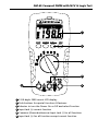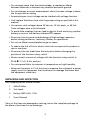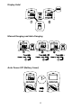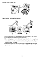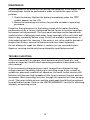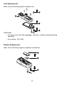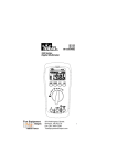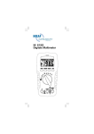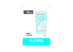
1
AM-60
Compact DMM with
NCV & Logic Test
Users Manual
•
•
•
•
Mode d’emploi
Bedienungshandbuch
Manual d’Uso
Manual de uso
AM-60
Users Manual
©2009 Amprobe Test Tools.
All rights reserved. Printed in China
English
Compact DMM with
NCV & Logic Test
Limited Warranty and Limitation of Liability
Your Amprobe product will be free from defects in material and workmanship for 1 year from the
date of purchase. This warranty does not cover fuses, disposable batteries or damage from accident,
neglect, misuse, alteration, contamination, or abnormal conditions of operation or handling. Resellers
are not authorized to extend any other warranty on Amprobe’s behalf. To obtain service during the
warranty period, return the product with proof of purchase to an authorized Amprobe Test Tools
Service Center or to an Amprobe dealer or distributor. See Repair Section for details. THIS WARRANTY
IS YOUR ONLY REMEDY. ALL OTHER WARRANTIES - WHETHER EXPRESS, IMPLIED OR STAUTORY INCLUDING IMPLIED WARRANTIES OF FITNESS FOR A PARTICULAR PURPOSE OR MERCHANTABILITY,
ARE HEREBY DISCLAIMED. MANUFACTURER SHALL NOT BE LIABLE FOR ANY SPECIAL, INDIRECT,
INCIDENTAL OR CONSEQUENTIAL DAMAGES OR LOSSES, ARISING FROM ANY CAUSE OR THEORY.
Since some states or countries do not allow the exclusion or limitation of an implied warranty or of
incidental or consequential damages, this limitation of liability may not apply to you.
Repair
All test tools returned for warranty or non-warranty repair or for calibration should be accompanied
by the following: your name, company’s name, address, telephone number, and proof of purchase.
Additionally, please include a brief description of the problem or the service requested and include
the test leads with the meter. Non-warranty repair or replacement charges should be remitted in the
form of a check, a money order, credit card with expiration date, or a purchase order made payable to
Amprobe® Test Tools.
In-Warranty Repairs and Replacement – All Countries
Please read the warranty statement and check your battery before requesting repair. During the
warranty period any defective test tool can be returned to your Amprobe® Test Tools distributor
for an exchange for the same or like product. Please check the “Where to Buy” section on www.
amprobe.com for a list of distributors near you. Additionally, in the United States and Canada InWarranty repair and replacement units can also be sent to a Amprobe® Test Tools Service Center
(see next page for address).
Non-Warranty Repairs and Replacement – US and Canada
Non-warranty repairs in the United States and Canada should be sent to a Amprobe® Test Tools
Service Center. Call Amprobe® Test Tools or inquire at your point of purchase for current repair
and replacement rates.
In USA In Canada
Amprobe Test Tools Amprobe Test Tools
Everett, WA 98203 Mississauga, ON L4Z 1X9
Tel: 888-993-5853
Tel: 905-890-7600
Fax: 425-446-6390 Fax: 905-890-6866
Non-Warranty Repairs and Replacement – Europe
European non-warranty units can be replaced by your Amprobe® Test Tools distributor for a
nominal charge. Please check the “Where to Buy” section on www.amprobe.com for a list of
distributors near you.
Amprobe® Test Tools Europe
In den Engematten 14
79286 Glottertal, Germany
tel: +49 (0) 7684 8009 - 0
*(Correspondence only – no repair or replacement available from this address. European
customers please contact your distributor.)
AM-60 Compact DMM with NCV & Logic Test
1
2
3
5
4
6
1 3-3/4 digits 2000 counts LCD display
2 Push-buttons for special functions & features
3 Selector to turn the Power On or Off and select Function
4 Input Jack (+) current function
5 Common (Ground reference) Input Jack (-) for all functions
6 Input Jack (+) for all functions except current function
AM-60 Compact DMM with NCV & Logic Test
CONTENTS
SYMBOLS................................................................................................................2
UNPACKING AND INSPECTION .............................................................................3
INTRODUCTION......................................................................................................4
OPERATION.............................................................................................................4
SPECIFICATION ......................................................................................................8
MAINTENANCE.......................................................................................................12
TROUBLE SHOOTING..............................................................................................12
Fuse Replacement .............................................................................................13
Battery Replacement ........................................................................................13
1
SYMBOLS
X
Warning! Dangerous Voltage (Risk of electric shock).
�
Caution ! Refer to the user’s manual before using this Meter.
T
Double Insulation or Reinforced insulation
B
Alternating Current (AC).
F
Direct Current (DC).
N
Low battery indicator
I
Fuse
J
Ground (maximum permitted voltage between terminal and
ground).
�
Please remove all the test leads before preforming maintenance,
cleaning, battery replacement, fuse replacement, etc
�
Complies with European Directives
�
Conforms to relevant Australian standards
=
Do not dispose of this pruduct as unsorted municipal waste.
Contact a qualified recycler for disposal
�Warnings!
• Do not operate this meter in explosive gas (material), combustible gas
(material) steam or filled with dust.
• When using test leads or probes, keep your fingers behind the finger
guards.
• Remove test lead from Meter before opening the battery door or Meter
case.
• Use the Meter only as specified in this manual or the protection by the
Meter might be impaired.
• Always use proper terminals, switch position, and range for
measurements.
• Never attempt a voltage measurement with the test lead inserted into
the A input terminal.
• Verify the Meter’s operation by measuring a known voltage. If in doubt,
have the Meter serviced.
2
• Do not apply more than the rated voltage, as marked on Meter,
between terminals or between any terminal and earth ground.
• Do not attempt a current measurement when the open voltage is above
the fuse protection rating.
• Suspected open circuit voltage can be checked with voltage function.
• Only replace the blown fuse with the proper rating as specified in this
manual.
• Use caution with voltages above 30 Vac rms, 42 Vac peak , or 60 Vdc.
These voltages pose a shock hazard.
• To avoid false readings that can lead to electric shock and injury, replace
battery as soon as low battery indicator N appears.
• Disconnect circuit power and discharge all high-voltage capacitors
before testing resistance, continuity, diodes, or capacitance.
• Do not use Meter around explosive gas or vapor.
• To reduce the risk of fire or electric shock do not expose this product to
rain or moisture.
• Disconnect the test leads from the test points before changing the
position of the function rotary switch.
• Never connect a source of voltage with the function rotary switch in
e / G
/ FBA / E /Hz position.
• Do not expose Meter to extremes in temperature or high humidity.
• Never set the meter in FBA function to measure the voltage of a power
supply circuit in equipment that could result in damage the meter and
the equipment under test.
Unpacking and Inspection
Your shipping carton should include:
1
AM-60 Meter
2
Test Leads
2
Battery (SIZE AAA, 1.5V)
1
User’s Manual
If any of the items are damaged or missing, return the complete package to
the place of purchase for an exchange.
3
INTRODUCTION
Multimeter AM-60 can be used to measure voltage, resistance, capacitance,
frequency, current; It is an electronic measuring instrument that combines
several measurement functions in one unit. AM-60 multimeter is portable
hand-held devices useful for basic fault finding and field service work or a
bench instrument which can measure to a very high degree of accuracy. They
can be used to troubleshoot electrical problems in a wide array of industrial
and household devices such as batteries, motor controls, appliances, power
supplies, and wiring systems.
Operation
Measuring AC/DC Voltage And Frequency
Testing for Continuity and Diode
4
Resistance and Capacitance
Note – To improve the measurement accuracy of small value capacitor, record
the reading with the test leads open then substract the residual capacitance of
the Meter and leads from measurement.
CUNKNOWN = CMEASUREMENT - CRESIDUAL
MIN MAX Record
Measuring DC / AC Current
5
Display Hold
Manual Ranging and Auto Ranging
Auto Power Off (Battery Saver)
6
Disable Auto Power Off
Non-Contact Voltage (Volt sense)
1. Volt sense switch will be activated on any function or at OFF status.
2. Test leads are not used for the Volt sense test.
3. Press the Volt sense button. The display goes black, a tone sounds and
the red LED lights up to verify the instrument is operational. The Volt
sense button must be held down to detect the presence of voltage
without use of the leads.
4. If a voltage of 50V to 600V (50 to 500Hz) is detected near the top of
meter a continuous tone sounds and the red LED near the top of meter
Illuminates.
7
SPECIFICATIONS
General Specifications
Display : 2000 counts.
Polarity Indication : Automatic, positive implied, negative indicated.
Overrange Indication : “OL” or “-OL”.
Batteries Life : Alkaline 250 hours
Low Batteries Indication : “N” is displayed when the batteries voltage
drops below operating voltage.
Auto Power Off : Approx 10 minutes.
Operating Ambient : Non-condensing ≦50°F, 51.8°F ~ 86°F
(≦80% R.H) 87.8°F ~ 104°F (≦75% R.H),
105.8°F ~ 122°F (≦45% R.H)
Storage Temperature : -4°F to 140°F , 0 to 80% R.H. when battery
removed from Meter.
Temperature Coefficient :0.15 x (Spec. Accy) /°F ,< 64.4°F or >
82.4°F.
Measure : Samples 2 times per second nominal.
Altitude : 6561.7 ft (2000m)
Safety : Complies with EN61010-1, UL61010-1,
IEC 61010-1,
V/e : CAT.III. 600V, CAT.II. 1000V.
A:
CAT.III. 500V
Pollution degree : 2
Power Requirements : 1.5V x 2 IEC LR03, AM4 or AAA size
Dimensions (W x H x D) : 74mm (2.9”) x 156mm (6.1”) x 44mm (1.7”)
Weight : 320g (0.71lb) including battery.
Accessories : Battery (installed), Test leads and user manual.
Electrical Specifications
Accuracy is ±(% reading + number of digits) at 23°C ± 5°C < 80%RH.
8
DC / AC Volts
Range
AC Accuracy
200.0mV *
Unspecified
2.000V *
±(1.5%+5dgt) 50Hz ~ 300Hz
20.00V ~ 200.0V *
±(1.5%+5dgt) 50Hz ~ 500Hz
750V AC / 1000V DC
DC Accuracy : ±(0.5% + 2dgt)
Over voltage protection : 1000V DC or 750 V ACrms.
Input Impedance : 10Me // less than 100pF.
* CMRR / NMRR : (Common Mode Rejection Ratio)
(Normal Mode Rejection Ratio)
VAC : CMRR > 60dB at DC, 50Hz / 60Hz
VDC : CMRR > 100dB at DC, 50Hz / 60Hz
NMRR > 50dB at DC, 50Hz / 60Hz
AC Conversion Type :
Average sensing rms indication.
AC conversions are ac-coupled, true rms responding,
calibrated to the sine wave input.
* The minimum LCD reading is 1400 count in Auto Ranging Mode.
Crest Factor : C.F. = Peak / Rms
+ 1.5% addition error for C.F. from 1.4 to 3
+ 3% addition error for C.F. from 3 to 4
DC / AC Current
Range
DC Accuracy
AC Accuracy
Voltage
Burden
±(1.0% + 3 dgt)
±(1.5% + 5 dgt)
50Hz ~ 500Hz
*
2V max
2.000A
10.00A **
Overload Protection :
A input : 10A (500V) fast blow fuse
9
* AC Conversion Type : Conversion type and additional specification are same
as DC/AC Voltage.
** Ampere Testing Duty Ratio Table
Ampere
Testing Time
Rest Time
10A
1min
10min
9A
2min
10min
8A
3min
10min
7A
4min
10min
6A
5min
10min
5A
Continually
N/A
Voltage Burden
Resistance
Range
Accuracy
200.0~200.0Ke **
±(0.7% + 3 dgt)
2.000Me **
±(1.0% + 3 dgt)
20.00Me *
±(1.5% + 3 dgt)
2V max
Open circuit Voltage: -1.3V approx.
* < 100 dgt rolling.
** The minimum LCD reading is 1400 count in Auto Ranging Mode.
Diode Check and Continuity
Resolution
Accuracy
10 mV
±(1.5% + 5 dgt)*
* For 0.4V ~ 0.8V
Max.Test Current : 1.5mA
Max. Open Circuit Voltage : 2V
Overload Protection : 600V rms.
10
Frequency
Range
Sensitivity
2000Hz ~ 200.0KHz
>1.5 Vac rms,
<5 Vac rms
2.000MHz ~ 20.00MHz
>2 Vac rms,
<5 Vac rms
Accuracy
Frequency :
0.01%±1digit
Overload Protection : 600V rms.
Minimum pulse width : >25 ns
Duty cycle limits : >30% and <70%
Capacitance
Accuracy
Overload
Protection
±(1.9% + 8 dgt)
600V rms
Range
2.000nF ~ 200.0µF
2.000mF *
* < 10 dgt of reading rolling.
� - EMC: EN61326-1.
This product complies with requirements of the following European
Community Directives: 89/ 336/ EEC (Electromagnetic Compatibility) and 73/ 23/
EEC (Low Voltage) as amended by 93/ 68/ EEC (CE Marking). However, electrical
noise or intense electromagnetic fields in the vicinity of the equipment may
disturb the measurement circuit. Measuring instruments will also respond to
unwanted signals that may be present within the measurement circuit. Users
should exercise care and take appropriate precautions to avoid misleading
results when making measurements in the presence of electronic interference.
11
MAINTENACE
If there appears to be a malfunction during the operation of the meter, the
following steps should be performed in order to isolate the cause of the
problem.
1. Check the battery. Replace the battery immediately when the “N”
symbol appears on the LCD.
2. Review the operating instructions for possible mistakes in operating
procedure.
Except for the replacement of the battery, repair of the meter should be
performed only by a Factory Authorized Service Center or by other qualified
instrument service personnel. The front panel and case can be cleaned with
a mild solution of detergent and water. Apply sparingly with a soft cloth and
allow to dry completely before using. Do not use aromatic hydrocarbons or
chlorinated solvents for cleaning. If the meter is not to be used for periods of
longer than 60 days, remove the batteries and store them separately
Do not attempt to repair this Meter. It contains no user-serviceable parts.
Repair or servicing should only be performed by qualified personnel.
TROUBLE SHOOTING
If the instrument fails to operate, check batteries and test leads etc., and
replace as necessary. Double check operating procedure as described in this
user’s manual.
If the instrument voltage-resistance input terminal has subjected to high
voltage transient (caused by lightning or switching surge to the system) by
accident or abnormal conditions of operation, the series fusible resistors will
be blown off (become high impedance) like fuses to protect the user and the
instrument. Most measuring functions through this terminal will then be open
circuit. The series fusible resistors and the spark gaps should then be replaced
by qualified technician. Refer to the LIMITED WARRANTY section for obtaining
warranty or repairing service.
12
Fuse Replacement
Refer to the following figure to replace fuse :
3
2
4
1
CAUTION:
• Use only a fuse with the amperage, interrupt, voltage, and speed rating
specified.
• Fuse rating : 10A, 500V
Battery Replacement
Refer to the following figure to replace the batteries:
2
3
1
13