1
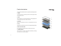
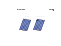
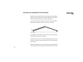
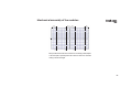
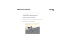
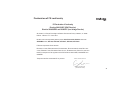
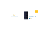
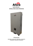
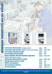
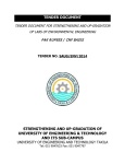
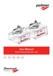
Instructions for use Ronda Isaac Peral y Caballero Parque Tecnológico 46980 Paterna - Valencia Tel.: +34 902 41 22 33 Fax: +34 96 070 92 65 [email protected] www.siliken.com Edition 01A Date: 14/04/2011 Photovoltaic module SILIKEN appreciates your support for our products. We recommend that you read this instruction manual carefully in its entirely before handling the photovoltaic module. Table of contents 1 Important safety instructions........................................................................ 3 2 Product description ....................................................................................... 4 3 Recommendations for use .......................................................................... 6 4 Product certificates and guarantee............................................................... 8 5 By-pass diodes..........................................................................................10 6 Operating voltage ......................................................................................13 7 Protection fuses.........................................................................................14 8 Warnings and electrical hazards ..................................................................16 9 Current-voltage curves ...............................................................................20 10 Mechanical assembly instructions ...............................................................22 11 Module maintenance..................................................................................33 12 Module frame grounding.............................................................................35 13 Declaration of CE conformity.......................................................................41 Safety instructions This instruction manual and the product labels contain a series of important safety messages. They should be read carefully before handling or connecting the photovoltaic module since the module produces electricity as soon as the cells are exposed to sunlight. ! The safety warning symbol is shown before each safety message included in this instructions manual. This symbol indicates that there is a personal safety hazard which would affect both you and others and cause damage to the products or other property. This user manual must not contradict any regulation that could have changed since the manuals last publication date. ! Warning: any fault in the module caused by failure to comply with the warnings stipulated in this instructions manual will lead to the complete withdrawal of the modules guarantee, together with the full exoneration of SILIKEN from any responsibility derived of any kind. 3 Product description Your photovoltaic Standard module is comprised of the following elements: 1 FRAME In anodised aluminium; providing a system for anchoring the module to the support structure. 2 GLASS Ultra-transparent 3.2 mm thick tempered glass; providing rigidity to the unit and protecting the active surface of the cells. 3 and 5 EVA (Ethylene Vinyl Acetate); its function is to encapsulate the cell circuit 4 CELLS 2 3 4 Highly efficient crystalline silicon solar cells. These generate the electricity. 5 6 BACK ISOLATION SHEET 6 Providing electrical insulation to the rear surface of the module. 7 7 CONNECTION BOX. IP65 specification. Providing a simple method of electrically connecting the module to the rest of the installation. 4 1 Recommendations for use Ensure that the module is located appropriately: it must not be placed beneath the shade of streetlights, trees, other buildings or even shade produced by other modules. Electricity production can be considerably reduced by the effect of shade. Install the PV module allowing air to circulate freely (see also section 6 of this manual). This will facilitate the natural ventilation of the module. The module is designed to work in temperatures between -40ºC and +85ºC (-40ºF and +185ºF). In addition, both polycrystalline modules produce more energy in lower temperatures. Therefore, proper ventilation favors higher power generation. It is important to orient the active surface of the modules towards the south as much as possible in the northern hemisphere, and towards the north as much as possible in the southern hemisphere. The metal support structure for the photovoltaic modules should be connected to ground in the manner indicated in the Low Voltage Directive 93/68/EEC and 2006/95/EEC and National Electrical Code. Ensure that the cables of the installation that connect modules to other modules, as well as those that lead to the load regulator, batteries or any other part of the installation, are not too tight since this could damage module connections or the cables themselves. Use cable ties or cable clamps to fix the cables to the structure. Do not leave connectors unplugged for long periods of time; dirt may 5 Recommendations for use prevent subsequent connection. We recommend that the modules are connected in short-circuit to avoid this. Respect the electrical polarity of the modules. You must remember that they are direct current modules and, as such, direct current is required for their correct operation. In addition, when connecting the different components of an isolated installation, you must always connect the batteries first, followed by the module, and finally the power supply. Do not use the connection box or the connection cables to hold or transport the module. You could damage some of its components and affect its waterproofness as well as the electrical security. Always handle the module with care, even if it has the aluminium frame. Any blow on the glass or on a corner of the frame could deform it enough to break the glass. Do not dismantle, modify or adapt the PV module. Do not remove any part or the identification label from a PV module installed by Siliken. If you do so, the guarantee will be invalid. Do not apply paint or adhesives to the back side of the PV module. ! 6 WARNING: SILIKEN shall not be held responsible or liable for any possible decrease in the electricity production of the photovoltaic module supplied, nor shall it consider said reduction to be a manufacturing defect if it is the result of the failure to observe the recommendations for use described herein. Product certificates and guarantee Product certificates and guarantee Atakama photovoltaic standard modules have been designed and manufactured in accordance with (IEC) EN 61215, UL 1703 standards and complies with the safety standards Qualification of photovoltaic modules IEC61730 class A (class II). In order to comply with these international standards, high quality and durable materials have been used. In addition, Atakama has a series of rigorous quality controls established for each phase of the production process along with a final quality control of the output power for all manufactured modules. Siliken provides a 10 year guarantee for the materials of the photovoltaic module and against any possible defects of the photovoltaic module due to the manufacturing process. 7 By-pass diodes The photovoltaic module must be protected with by-pass diodes. The absence of these diodes could cause the photovoltaic module to malfunction or even ultimately lead to its destruction as it could catch on fire. Siliken delivers its modules with by-pass diodes included inside the connections box. The photovoltaic cells have two operating modes: it operates as a current generator or as a current consumer. A cell exposed to solar radiation provides a current ranging between 6 and 8 amps with a potential difference of around 0.6 volts. However, when a cell is partially shaded, by the leaves of a tree for example, it starts to consume the electricity generated by the other cells to which it is connected. At the area of the cell that changes from a sunlit area to a shaded area, an effect known as a "hot-spot" occurs whereby, due to the circulation of current, the overheating produced is such that it may set the materials on fire and destroy the module. The maximum number of cells connected in series per diode is 20 cells for Atakama PV modules. 8 By-pass diodes Normal operation Operation with the cell in the shade 9 By-pass diodes ! ! 10 WARNING: For the aforementioned reasons, it is important that the diodes are not removed from the connection box. In the event of by-pass diode failure, they must be replaced with original by-pass diode spares and by personnel authorized and trained by Siliken. From the moment that the failure in the diodes occurs and until they are replaced, the affected photovoltaic module(s) must remain disconnected from the other modules on the photovoltaic array, thus guaranteeing that the circuit remains open. In any event, the decision to change the diodes is the responsibility of Siliken. WARNING: Failure to use original spares or parts replaced by personnel without the authorisation of SILIKEN, etc., shall lead to the withdrawal of the guarantee of the photovoltaic module and SILIKEN shall automatically be exonerated from any responsibility for damage caused to property or harm caused to people. Operating voltage The maximum voltage of the system is 1000 V in Europe (see module label) and 600 V in USA (see module label). The maximum number of modules to be connected in series (in cell temperature conditions of 77ºF / 25°C), is 16 in USA and 24 in Europe ! WARNING: the value for the maximum number of modules must be corrected based their location and in accordance with the correction parameters provided in the formula, since the voltage increases as the temperature decreases. Calculate the value based on the lowest temperature in the region where the modules will be installed. Max. no. of modules Voc77°F Maximum system voltage a + (( T - 77 ) x no cell x (-0.00215)) 11 Protection fuses ! ! Attention: Under normal conditions, a photovoltaic module is likely to experience conditions that produce more current and/or voltage than reported at standard test conditions. Accordingly, the values of ISC and VOC marked on this module should be multiplied by a factor of 1.25 when determining component voltage ratings, conductor ampacities, fuse sizes, and size of controls connected to the PV output. Attention: Refer to Section 690-8 of the National Electrical Code for an additional multiplying factor of 125 percent (80 percent derating) which may be applicable. For field connections, use minimum No. 10 AWG copper wires insulated for a minimum of 194°F / 90 ºC. Once the modules are connected in series to obtain the correct input voltage for each type of inverter it is essential that protection fuses are located between the inverter and each series. These fuses will facilitate maintenance and control tasks, but they will mainly protect the series from each other should the polarity of one of the series of modules be incorrectly connected. Series fuse (overcurrent protection) rating of 15 A. 12 Protection fuses The design level current for these fuses must be multiplied by a factor of 1.25 times the Isc of the photovoltaic module measured under standard test conditions (92.94 W/ft2 and 77 ºC) / (1,000 W/m2 and 25°C). The fuses must be suitable for direct current systems, with a breaking capacity greater than the sum of the intensities of the series of connected modules, using the method indicated in the National Electrical Code. Failure to install this type of protection, in the event of an incorrect positive and negative polarity connection, will cause the reversed series to act as an electricity receiver causing severe damage to both the diodes and the other electrical components of the modules. ! WARNING: Failure to comply with the provisions of this section will lead to the loss of guarantee and the exoneration of Siliken from any type of responsibility for damage to property or injury to people. 13 Warnings and electrical hazards The installation, handling and maintenance of the photovoltaic modules must be carried out by qualified personnel duly equipped with individual protections. For information purposes, these protections include: safety boots with insulation for above 1000V, gloves with 1000V insulation, as well as a helmet and appropriate clothes. Contact with VAC (VDC) voltage equal or higher than 30 V is potentially dangerous. Do not use PV modules with different electrical or physical configurations in a single PV system. Keep children away from the system and the PV modules during installation. Do not carry out the installation in heavy rain or wind. For handling electrical components, always use appropriate tools covered with insulating materials. It is recommended to avoid handling modules in humid conditions. Before handling and installing PV modules, remove your rings and other metal jewels. It is important to remember that the active front panel of the module is made of glass and can break if it receives an impact. In cases of broken glass, the module must not be installed as it will have lost the electrical insulation of the cells and will have a much lower performance level. 14 Warnings and electrical hazards Do not allow objects to fall on the photovoltaic module, and do not sit on, lean on, or walk on the photovoltaic module, on either side (glass or rear sheet), given that it could cause the cells to break and therefore significantly lower the power and energy performance of the modules. Do not open the connection box of the photovoltaic module. The cover of the connection box has a safety seal to guarantee to the customer that it has been correctly sealed to provide IP65 level of protection. If the cover is not correctly sealed, there is a risk of damage to the module due to water ingress. Do not disconnect the terminals of the modules if they are electrically connected to other devices of the system. Before loosening connectors, disconnect the modules from the inverter or the battery charger using switches. Before handling any electrical parts of the PV installation, cover the active surface of the module from sun light. Do not use mirrors or magnifying lenses to concentrate light on the PV modules, they were not designed for this. When handling and installing the module, we recommend covering the active surface of the photovoltaic module since the modules generate electricity when they are exposed to any source of light even when they are not connected to any other device. 15 Warnings and electrical hazards Do not remove any of the modules components or remove the technical specifications label. Do not place the installation near to any possible source of inflammable gases or vapors, since the photovoltaic modules can cause sparks just like any other electrical component. Always ensure the installation is equipped with protection devices against electrical hazards. Remember that when the modules are connected in series, the voltage present will be the sum total of the voltage from each module, and when the modules are connected in parallel, the current present will be the sum total of the current from each module. This means that an installation with various modules may contain high levels of voltage and current. When screwing the frame of the module to the structure, avoid rubbing against the plastic insulation on the rear surface of the module (Tedlar) with the tool or elements protruding from the structure because this could cause the plastic to tear, causing a loss of electrical insulation. 16 The PV module produces power even with a broken glass or back sheet. Do not dispose of the module in containers or dumping sites, this can be dangerous. If the glass or the back sheet is broken, in case of Warnings and electrical hazards electrical failure or if the service life of the module ends due to any cause in general, please contact Siliken to appropriately eliminate and/or recycle the product according to American/European norms. Consult the fire security regulations, norms and prerequisites for buildings and structures with your local authorities. Keep in mind that a roof-top construction and installation may affect the buildings fire security; erroneous installation of PV modules can increase this risk in case of fire. The assembly is to be mounted over a fire resistant roof covering rated for the application. The modules are qualified for application class A: Hazardous voltage (IEC 61730: higher than 50V DC; EN 61730: higher than 120V), hazardous power applications (higher than 240W) where general contact access is anticipated (Modules qualified for safety through EN IEC 61730-1 and -2 within this application class are considered to meet the requirements for Safety Class II. ! WARNING: Failure to comply with the provisions of this section will lead to the loss of guarantee and the exoneration of Siliken from any type of responsibility for damage to property or injury to people. 17 Current-voltage curves The graphs of the technical data sheets show the behaviour of the photovoltaic modules. Two types of Current-Voltage curves (I-V) are shown: - At different radiations and constant temperature (77 ºF / 25°C). - At different temperature and constant radiation (92.94 W/ft2 / 1000 W/m2). The standard test conditions or STC used for module labelling are: Radiation = 92.94 W/ft2 / 1000 W/m2 Cell temperature = 77 ºF / 25 ºC Air Mass = 1.5 It must be noted that the voltage and current behaviour of the cells depends on the solar radiation and temperature. Therefore, the actual operating conditions of a photovoltaic module will depend on the region where the module is installed and the ambient conditions in that region. The voltage dependence in relation to radiation is defined by a logarithmic function: at low radiation levels a high voltage is obtained. However, the current dependence in relation to radiation is defined by a linear function: it increases in direct proportion to the increase in solar radiation. 18 Current-voltage curves The voltage and current dependence with temperature is defined by a linear function. On one hand the voltage decreases as the temperature increases at a ratio of 2.15 mV/ ºC per cell in series. On the other, the current increases at +3.50 mA/ºC. Therefore, of the 7.5 to 8 amps that the module is capable of generating at 77º F / 25°C, the current increases slightly with each degree centigrade of increase in the module temperature, while the voltage decreases. In general, we observe a decrease of the photovoltaic module power as the operating temperature increases, at a ratio of -0.47%/ºC. For example, a module of 220 Wp will lose 0.95 Wp for every additional °C in the cells. The module operates at between 122 and 158 ºF / 50 and 70°C when it generates electricity with radiation of between 800 and 1100 W/m2 and a wind speed of less than 1 m/s. 19 Mechanical assembly of the modules The indications stated below are general for any type of module: When assembling the modules, the safety conditions stipulated in the Low Voltage Directive 93/68/EEC and 2006/95/EEC and the Framework Directive on Safety and Health at Work 89/391/EEC, 91/383/EEC, 2003/134/EEC, 89/654/EEC, 89/655/EEC, 89/656/EEC, 92/57/EEC and 92/58/EEC. Standard Modules must be anchored in a secure manner, using special fixing systems or assembly sets for photovoltaic systems. The ideal orientation for the photovoltaic module is towards geographic south in the northern hemisphere or towards geographical north in the southern hemisphere. The inclination of the module will depend on the requirements of the installation itself (grid connection systems or isolated supply). Install the module so that the connection box cable holders are never oriented upwards in the direction of the inclination. 20 Mechanical assembly of the modules cable glands 21 Mechanical assembly of the modules Siliken recommends that the modules not be installed at reduced inclination angles that could cause dirt to accumulate on the glass or on the edges of the frame. Siliken recommends a minimum inclination of 5º. In the case of roof-top PV modules, leave space at their back side to allow for proper ventilation (minimum of 50 mm [1.97 inches]). 50 (1.97") VENTILATION For integrated modules that serve as a roof tile, it must be assured that the rear part of the modules is ventilated. A photovoltaic module is not a structural element. Be sure that the module is not going to support any load that could cause the tempered glass to break. Maximum permitted loads for PV modules refer to uniformly distributed loads of wind and/or snow. Therefore, do not install PV modules in areas 22 Mechanical assembly of the modules in which snow tends to accumulate or icicles and/or ice plugs could obstruct water drainage and cause damage to the module. In areas with heavy snowfall, adjust the height of the mounted structure so that snow does not cover any active part of the front side or any back parts, such as the connection box or cables, for a prolonged period of time in winter. The modules with frames are supplied with 4 holes on the aluminum frame, at the distances and with the diameters that are specified in the data sheets of the products. These holes are used to secure the module to a structure which must have been designed by a qualified technician to support the loads produced by wind and snow, as indicated in the Directive of Construction (89/106/EEC) and the Directive 2002/91/EEC Energy Efficiency Building. The module must be mechanically fixed at least at these four points. The module is certified when anchored with M8 bolts in 4 fixing holes on the frame, with a minimum torque of 10 Nm (7.4 ft-lbf) and a maximum of 15 Nm (11.1 ft-lbf). Use tools for checking the torque. It is recommended the use rubber joints (long-lasting synthetic rubber) 23 Mechanical assembly of the modules to avoid direct contact between the metal parts of the PV module and the supporting structure as well as to prevent possible deformations of the parts that could damage the module. Other fastening methods that attach the module around the perimeter are also acceptable, such as those designed for integration on roofs or similar methods. A minimum space of 5 mm must be left between modules in order to prevent contact between them due to thermal expansion. For less space between modules, rubber gaskets that prevent contact must be used. The recommended layout in the event that anchor clamps are used for the module with a frame is the layout shown in the following schematic of the Atakama PV modules. 24 Mechanical assembly of the modules 330 5 330 330 5 330 Always shield the modules back surface from contacting outside objects or structure parts, especially when the module is under load. The back coating could be damaged. 25 Mechanical assembly of the modules For any questions, please contact the Technical Department of Siliken ! WARNING: Failure to comply with the provisions of this section will lead to the loss of guarantee and the exoneration of Siliken from any type of responsibility for damage to property or injury to people. For any modification that may need to be made to what is detailed in this section of the user manual, contact Siliken in order to jointly evaluate the possibility of allowing any such variations, which may be necessary in specific cases of some photovoltaic module installation systems. 26 Module maintenance Atakama photovoltaic modules require a minimum level of maintenance throughout their useful life, which includes the following operations: Cleaning of the photovoltaic modules. The energy production of the solar module can be affected if the glass is dirty. Periodically clean the modules to guarantee maximum production. The steps below should be followed: Spray the front surface of the PV module with plenty of water at ambient temperature and at low pressure for approximately 3 minutes. Pressurized water (max. of 100 bar) can also be used from a distance of no less than 50 cm. Clean the front surface with a soft polyurethane sponge or a soft cotton cloth by wiping in circular motions. Rinse the front surface of the PV module with plenty of water to eliminate any remaining dirt. ! Do not use detergents or cleaning products, chemical products, metal elements, cutting tools, scrapers or sharp instruments, which can damage the glass surface. This could cause a decrease of output power. 27 Module maintenance Check the tightness and condition of the electrical connectors annually. Visually inspect the cables and compression glands. Visually inspect the front face of the photovoltaic modules to verify that there are no defects. ! WARNING: Failure to perform the checks and minimum maintenance operations established in these instructions will lead to the withdrawal of all guarantees and the exoneration of SILIKEN for any responsibility which may be derived from said failure. For any additional information related to the modules Atakama ATK-P60 series please refer to the annexed technical data sheets. 28 Module frame grounding All exposed metal parts of PV module frames must be grounded during installation (per NEC 690.43), and to accomplish this Siliken recommends the following components: (1) M4 AISI304 stainless steel bolt with hexagonal nut. (2) DIN67982 stainless steel serrated washers. (1) Cable gland type connector for 10 AWG cable with washer for M4 bolt. Assemble as shown in the following diagram: 29 Module frame grounding The ground connection must be made using green and yellow cables with a cross-section of 2.5 mm2 or more and with plastic insulation that is suitable for a minimum temperature of 90º C. While crystalline PV modules are not likely to polarize and their operation is not usually harmed by these types of effects, it is advisable to protect the negative polarity of the cells from possible electrical signals that are uncontrollable or unpredictable. It is advisable to avoid high potential differences between the glass assembly and the frame with respect to the negative of the module series. This can cause the glass and encapsulating materials to become positively charged, which could affect the electrical operation of the module and thus reduce its performance. Before making any type of connection to protect the module from the effects of polarization, be sure to consult the inverter manufacturer to see if it can be connected adequately to protect against these kinds of effects. Do not use the ground of the structure or of the modules frame to provide this type of protection against polarization. This could be hazardous. 30 Declaration of CE conformity EC-Declaration of Conformity Directive 2004/108/EC (EMC Directive), Directive 2006/95/EEC and 93/68/EEC (Low Voltage Directive) We, Siliken, S.A. Parque Tecnológico de Paterna. Ronda Isaac Peral y Caballero, 14. 46980 Paterna - Valencia. C.I.F. A-97114516. Declare under sole responsibility that the product Solar Photovoltaic Modules trade mark ATAKAMA models, ATK-P60, ATK-P60S, ATK-P60T, ATK-P60U, ATK-P60V. Fulfils the requeriments of the standard: EN 61000-6-1:2007, EN 61000-3:2007, EN 60270:2002, EN 61140:2002+A1:2006, EN 617302:2007, EN 60664-1:2007, EN 60664-3:2003+A1:2010, EN 60664-5:2007, EN 61730-1:2007 and therefore corresponds to the regulations of the EC-Directives 2004/108/EC, 2006/95/EEC and 93/68/EEC The product was first marked with CE on year 2011. Paterna, Valencia, March 2011 Gonzalo J. Navarro Paulo (Chief Executive Officer) 31 Notes 32 Instructions for use Ronda Isaac Peral y Caballero Parque Tecnológico 46980 Paterna - Valencia Tel.: +34 902 41 22 33 Fax: +34 96 070 92 65 Edition 01A Date: 12/04/2012 Photovoltaic module