1
Contents
INTRODUCTION .................................................................................................. 1
OPTIONAL FEATURES ......................................................................................... 1
BASIC OPERATION ............................................................................................. 2
SYSTEM OVERVIEW ............................................................................................ 3
OPERATOR CONTROLS AND DISPLAY PANEL .......................................................... 4
DUAL BUTTON FUNCTIONS ................................................................................. 6
SPECIAL BUTTON FUNCTIONS .............................................................................. 6
MODES OF OPERATION ...................................................................................... 6
MODES OF OPERATION ...................................................................................... 7
FAN MODES ..................................................................................................... 7
PROGRAM MODE .............................................................................................. 8
ENTERING PROGRAM MODE ............................................................................... 8
USING THE PROGRAM MODE .............................................................................. 9
PROGRAMMING ................................................................................................. 9
FAIL-SAFE AND FAULT HANDLING CODES .......................................................... 13
SPECIFICATIONS .............................................................................................. 15
DIMENSIONS ................................................................................................... 15
CABLE LENGTHS ............................................................................................. 15
SYSTEM INPUTS ............................................................................................... 15
SPECIFICATION NOTES ..................................................................................... 16
AUTOMATED FACTORY-SELF TEST PROGRAM ..................................................... 16
SERVICE TOOLS ............................................................................................... 17
WIRING DIAGRAM..................................................................................................... 18
INSTALLATION OVERVIEW .....................................................................................19
Copyright © 1997 Micro Air Corporation, All Rights Reserved
No part of this publication may be reproduced, translated, stored in a retrieval system, or transmitted on any form
or by means electronic, mechanical, photocopying, recording or otherwise without prior written consent by Micro
Air Corporation.
Every precaution has been taken in the preparation of this manual to insure its accuracy. However, Micro Air
Corporation assumes no responsibility for errors and omissions. Neither is any liability assumed for damages
resulting from the use of this product and information contained herein.
FX-Maxx Operations Manual
INTRODUCTION
The FX-Maxx Control is designed for use with all direct expansion, reverse cycle air conditioning
systems. FX-Maxx has a universal power supply that operates on 115, 230, 50 or 60 Hz AC power.
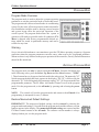
FX-Maxx includes the following standard and optional features:
Standard Features
User friendly 6 button display panel requires no manual for basic operation
Five volt logic and micro controller located in the display
3 - digit 7 - segment display panel indicates °Fahrenheit or °Celsius
Paintable Face Plate Cover with recess for matching wall covering insert
Automatic fan speed reduction as set point is approached
Six [6] programmable manual fan speeds
16 programmable parameters for custom installations
AC voltmeter to protect valuable electrical components
High and low Freon pressure sensor inputs
Moisture Mode for controlling relative humidity
De-Icing cycle to prevent evaporator coil icing
Programmable multiple compressor staging delays
Universal AC power supply
Nonvolatile memory retains settings without batteries
Programmable display brightness control for night use
OPTIONAL FEATURES
The following optional items can be added by plugging the device into the appropriate jack and
making the necessary programming changes.
Outside air temperature sensor… No programming necessary.
Alternate air temperature sensor… No programming necessary.
Custom Paintable display panels
Pump Guard water sensor… Program setting of P-8 required.
This manual is intended to provide information necessary to insure proper installation and
operation of the FX-Maxx. Poor installation and MISUNDERSTOOD operating parameters will result
in unsatisfactory performance and premature failure of the FX-Maxx.
Read This Manual Completely Before Proceeding !
If you require assistance prior to or during the installation of the FX-Maxx call Micro Air at 609259-2636 or Fax your questions to Micro Air at 609-259-3063.
The FX-Maxx is covered under existing Micro Air Warranty Policy. Incorrect installation, neglect
and system abuse are not covered under Micro Air warranty policy.
Revision: 06
04 / 08 / 09
Page 1
FX-Maxx Operations Manual
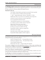
BASIC OPERATION
POWER BUTTON Press the power button once to toggle the unit to the on mode. Press the power
button again to toggle the unit to the off mode.
FAN BUTTON Press and release the fan button
to advance from auto to manual fan. Press and
release to increase the manual fan speeds, 1
through 6. Press and release again returns to the
auto fan mode. The selected fan mode is indicated by the Auto and Manual fan LED's
UP BUTTON Momentarily press and the set
point will appear in the temperature display. The
set point increases one degree each time the up
button is pressed and released.
DOWN BUTTON Momentarily press and release to display the set point. The set point is
decreased one degree each time the down button is pressed and released.
MODE BUTTON The mode button is used to select one of 4 Operating Modes. Press and release
to advance to the next mode. Continue to press and release until the desired Operating Mode is
reached. The mode selected is indicated by the Mode LED.
TEMP SELECT BUTTON Press and release to view inside [supply] air temperature, outside [return]
air temperature or set point. The appropriate LED will be lit indicating the temperature is displayed.
THREE DIGIT DISPLAY The inside [supply] temperature is displayed whenever the control is turned
on. The display provides a readout of the inside air temperature which is located in the supply duct.
HEAT MODE LED The heat mode LED is lit when Heating is selected.
COOL MODE LED The cool mode LED is lit when the Cooling is selected.
AUTO LED The auto LED is lit when the Automatic Heating or Cooling Mode is selected. The
control will automatically switch to heating or cooling when this mode is selected.
MOISTURE CONTROL LED The moisture LED is lit when the Moisture Control is selected.
MANUAL FAN LED The manual fan LED is lit when a manual fan speeds is selected.
AUTO FAN LED The auto fan LED is lit when automatic fan speed operation is selected.
FAN SPEED BAR GRAPH There are six [6] individual fan speed LED's. Each LED represents
one [1] fan speed. Low fan [1] is indicated by illuminating the first LED. High fan speed is indicated
by illuminating all six [6] LED's.
LED The system operating status [Compressor On or Off] is indicated by turning On the right most
decimal point in the 3 Digit Display.
Revision: 06
04 / 08 / 09
Page 2
FX-Maxx Operations Manual
SYSTEM OVERVIEW
FX-Maxx is a user friendly, easy to operate, programmable temperature control.
Press the ON/OFF button once to engage the system. The Display indicates room temperature when
the system is on and the Display is blank when the system is off.
Press and release the Mode Button until the desired Mode LED is illuminated.
Set the desired room temperature by pressing the up or down button. The set point can be viewed
by momentarily pressing and releasing the Up or Down Button.
Fan speed operation is automatic allowing fan speed to decrease as room temperature is approached. The fan speed decreases as the set point is approached. The fan will operate at low speed
when set point is satisfied. Manual fan speeds can be selected by pressing and releasing the fan
button to select the desired manual fan speed. The fan will operate at the speed selected and will
not change speeds with room temperature.
The fan can be programmed to cycle on and off with demand, allowing the fan to run only when
cooling or heating is required. Normally the automatic fan speed operation is reversed in the heating
mode, however, the fan can be programmed to operate the same as in the cooling mode.
NORMAL HEATING OR COOLING CYCLE
Select Cool only and cooling only will be supplied. The cabin temperature will be maintained within
2 ° F of the set point. Select Heat only and only heating will be supplied. The cabin temperature will
be maintained within 2 ° F of the set point.
Select Automatic and both heating and cooling will be supplied as required. While in the Automatic
Mode FX-Maxx will maintain a two degrees Fahrenheit (2 °F) temperature variation. A four degree
swing is required to cause the unit to shift to the opposite mode. Once in a given mode, heating or
cooling, FX-Maxx will maintain a two degree differential.
When the Heating or Cooling demand is satisfied, the compressor cycles off and the Automatic Fan
returns to low speed. The fan speed will remain constant if Manual Fan Speed has been programmed.
REVERSING VALVE OPERATION
The reversing valve is toggled to the opposite mode when heating or cooling is required to reduce
the compressor starting surge. The valve will only toggle to the opposite mode when a cooling or
heating cycle is called for and if the system has been off for less than seventy-five (75) seconds. The
valve will also toggle if a cycle is interrupted from the display panel by pressing the power button
ON/OFF, or changing the set point. Unnecessary valve toggling has been limited to reduce reversing
valve noise. Valve toggling can be totally eliminated by programming the minimum compressor
staging delay at seventy-five seconds (75) or greater.
Power on reset, which occurs when the system is powered up, will always initiate a valve toggle.
Memory: FX-Maxx has nonvolatile memory which requires no batteries or any form of backup
power. When power is lost the operating parameters are retained indefinitely. When power is
restored, the control resumes operating as last programmed. All operating and programming
parameters are entered into nonvolatile memory instantly and are retained indefinitely.
Revision: 06
04 / 08 / 09
Page 3
FX-Maxx Operations Manual
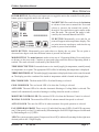
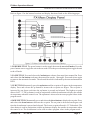
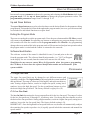
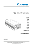
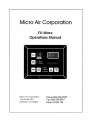
OPERATOR CONTROLS AND DISPLAY PANEL
Refer to figure 1 for the buttons locations and display functions listed on the following pages.
1. POWER BUTTON The power button is used to toggle between the on and off modes. Press the
power button once to toggle the unit to the on mode. Press the power button again to toggle the unit
to the off mode.
2. FAN BUTTON Press and release the fan button to advance from auto fan to manual fan. Press
and release the fan button to advance the manual fan speeds, 1 through 6. Press and release again
to return to the automatic fan mode. The selected fan mode is indicated by the auto and manual fan
LED's
3. UP BUTTON Momentarily press the up button and the set point will appear in the temperature
display. Press and release the up button to increase the set point one degree. The set point is
increased by one degree each time the up button is pressed and released. The highest set point
allowed is 85 ° F. The up button is used in conjunction with the down button to display the outside
air temperature when the control is on. The up button is also used to increase program values in the
program mode.
4. DOWN BUTTON Momentarily press and release the down button to display the set point. Press
and release the down button to decrease the set point. The set point is decreased one degree each
time the down button is pressed and released. The lowest set point allowed is 55 ° Fahrenheit. The
down button is used in conjunction with the up button to display the outside air temperature when
the control is on. The down button is also used to reduce program values in the program mode.
Revision: 06
04 / 08 / 09
Page 4
FX-Maxx Operations Manual
5. MODE BUTTON The mode button is used to select one of the four operating modes. Press and
release the mode button and the FX-Maxx will advance to the next mode. Continue to press and
release the Mode button until the desired operating mode is reached. The mode selected is indicated
by the Mode LED, i.e., Cool, Heat, Automatic or Moisture Mode.
6. TEMP SELECT BUTTON Press and release the Temp Select Button to view inside air
temperature, outside air temperature or the set point. The appropriate LED, Inside, Outside or Set
Point will be lit indicating which temperature is being displayed. If no outside air sensor is installed
three [3] dashes will appear in the Three Digit Display.
7. THREE DIGIT SEVEN SEGMENT DISPLAY The inside air temperature is displayed in the
window whenever the control is turned on. The three digit 7 segment display provides a readout of
the inside air temperature which is located in the face plate. An optional alternate air sensor is
available for installations that cannot use the face plate sensor.
The display also indicates program information, fault codes and outside air temperature when the
optional outside air sensor is installed.
The display momentarily indicates the set point when the up or down button is pressed.
When the control resumes operation after a power interruption all the display LEDs will turn on for
one second. This is a normal operating condition and is referred to as "Power On Reset".
8. HEAT MODE LED The heat mode LED will be lit when the Heat Mode has been selected. The
heat mode LED is also lit when the optional electric heat is installed and the heat mode is selected.
Electric heater status, on or off, is indicated by the right most decimal point [ 18 ].
9. COOL MODE LED The cool mode LED will be lit when the Cooling Mode has been selected
10. AUTO LED The auto LED is lit when the automatic heating or cooling mode has been selected.
The control will automatically switch to heating or cooling when this mode is selected.
11. MOISTURE CONTROL LED The moisture mode LED is lit when the Moisture Control has
been selected. This mode is used to control humidity during periods when the vessel is unoccupied.
12. MANUAL FAN LED The manual fan LED will be lit when one of six manual fan speeds has
been selected.
13. AUTO FAN LED The auto fan LED is illuminated when automatic fan speed operation has
been selected.
14. FAN SPEED BAR GRAPH There are six [6] individual fan speed LED's in the Fan Speed Bar
Graph. Each LED represents one [1] fan speed. Low fan speed [1] is indicated by illuminating the
first LED. High fan speed is indicated by illuminating all six [6] LED's. Any of the six [6] fan speeds
available are displayed by illuminating the appropriate LED's.
15. INSIDE LED The inside LED is lit when the inside air temperature is being displayed.
16. OUTSIDE LED The outside LED is turned on when the outside temperature is displayed.
17. SET POINT LED The set point LED is turned on when the set point is displayed.
18. COMPRESSOR LED The system operating status [Compressor On or Off] is indicated by
turning On the right most decimal point in the 3 Digit Display.
.
Revision:
06
04 / 08 / 09
Page 5
FX-Maxx Operations Manual
DUAL BUTTON FUNCTIONS
Up & Down Buttons… Press the up and down button together and the outside air temperature will
be displayed, providing the OPTIONAL OUTSIDE AIR TEMPERATURE SENSOR has been installed. No
programming is required. Press the UP & Down Buttons simultaneously, while in the program
mode, to set new custom programming defaults.
Power & Down Buttons… Simultaneously press the power and down buttons while viewing the
Service Fault History Log clears the fault History Log.
SPECIAL BUTTON FUNCTIONS
Special button functions are implemented by pressing and holding a particular button while the
controls' AC power is turned on.
1. Service History Log… View the service history log by pressing and holding the Mode Button
while turning on the AC power. Exit the service history log by pressing the power button once.
Clear the service history log by simultaneously pressing the power and down buttons.
2. Self Test Mode… Press and hold the power button while AC power is applied to enter the self
test mode. The self test is used to diagnose problems and test the air conditioning system. For
complete details see page 14 of this manual.
3. View Hour Meter… To view the compressor hour meter, press and hold the down button while
applying AC power. Maximum recorded time is 10,000 hours. The hour meter stops at maximum
(10,000 hrs) and can only be reset by Micro Air Corporation. The hour meter functions are described
fully on page 16 of this manual.
MODES OF OPERATION
Off Mode
When the FX-Maxx is in the off mode, all control outputs are turned off. Program parameters and
user settings are saved in nonvolatile memory. The program mode can only be accessed from the
off mode.
On Mode
When the control is in the on mode, power will be supplied to the appropriate control outputs and
the display will indicate the current state of operation. The operating and program parameters
resume based on those stored the last time the unit was operating.
Cool Only Mode
When Cool LED is on, only the cooling systems are selected and operated as required. When the
temperature drops below the set point, the system will not automatically switch to the heating
mode. Cooling only is available for customers that do not want automatic cooling and heating
operation. Systems without reverse cycle heating can have an optional electric heater installed
should heating be required.
Revision: 06
04 / 08 / 09
Page 6
FX-Maxx Operations Manual
Heating Only Mode
When the Heat LED is on, only the heating systems are selected and operated as required. Should
the temperature rise above the set point, the system will not automatically switch to the cooling
mode. Heating only is supplied for customers that require the system to not automatically switch
from the heating to the cooling mode.
MODES OF OPERATION
Automatic Mode
When the Automatic LED is on, both heating and cooling are supplied as required. The heat and
cool LEDs will be lit according to the mode required. When the system requires compressor
operation for heating or cooling the right most decimal point [18] will turn on when the compressor
is on.
Temperature in a given mode will be maintained at two degrees Fahrenheit 2 ° F), however, a four
degree difference is required to allow the control to change modes. Once in a new mode, the
temperature will remain within two degrees Fahrenheit 2 ° F) of the set point.
Moisture Mode
While in the on mode, press the Mode Button until the Moisture Mode LED is illuminated. Every
four (4) hours, the fan is started and air circulated for thirty (30) minutes. During this time the air
temperature is sampled and entered into memory. The cooling cycle is started and continues until
the temperature is lowered 2 ° F. The compressor is allowed a maximum of one hour running time
to reach the desired temperature. Four (4) hours after the temperature is satisfied or the compressor
the cycle will be repeated. The right most decimal point is lit while the compressor is running.
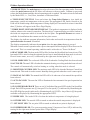
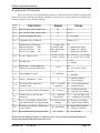
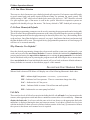
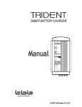
FAN MODES
Automatic Fan Speeds
FX-Maxx has six automatic fan speeds available. Speed six is high, three is
medium and one is low or the slowest speed. Automatic fan mode allows the
FX-Maxx to determine the required fan speed based on room temperature. The
closer the room temperature is to the set point, the slower the fan will run. This
permits a balance between the most efficient temperature control and slower,
quieter fan speeds. Automatic fan operation is the factory default, however,
manual fan speed control is available.
Manual Fan Mode
Six (6) is the fastest and one (1) represents the slowest speed. Manual fan
mode allows the user to select and maintain the desired fan speed manually.
When a manual fan speed has been selected, the fan speed bar graph will
indicate the speed selected by the number of LED's lit. Select speed 3, for
example, and the first 3 LEDs in the fan bar graph will turn on. Manual Fan
Mode is sometimes preferred when room temperature is constantly changing
due to varying heat loads.
Revision: 06
04 / 08 / 09
Page 7
FX-Maxx Operations Manual
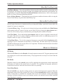
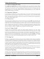
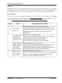
PROGRAM MODE
Program Mode Overview
The program mode is used to adjust the systems operating
parameters to suit the particular needs of individual users.
The program mode is also used to tailor the air-conditioning
system for the most efficient operation within an installation. Installation variables such as, ducting, sensor location
and system layout effect the perceived operation of the
overall system. The program mode allows the system to
operate as efficiently as possible under all conditions. FXMaxx is shipped with factory programmable default settings which are stored in permanent memory and can be
recalled at any time.
Warning
Severe electrical disturbances can sometimes upset the FX-Maxx operating sequences. Operator
confusion related to program parameters can also cause, what seem to be, operational problems.
Whenever there is any doubt as to the proper operation of the controller, Factory Default Parameters
should be Re-initialized.
ENTERING PROGRAM MODE
The program mode can only be entered from the Off Mode. From the Off Mode and
in the following order, press the Select, Up, Down and the Select buttons [ "SUDS"
]. These buttons have to be pressed and released in the order given. The numerals "85"
which represent the high fan limit, appears in the display. The "85" is followed by the
characters "P 1" followed again by the parameter setting [ "85" ]. P 1 represents the first
programmable parameter. The Fx-Maxx Air Handler Control is now in the program
mode. Exit the program mode, to the off mode, by pressing and releasing the power
button.
NOTE: The control will exit the program mode and return to the off mode if no
programming is attempted for one (1) minute.
Restore Memorized Default Settings
IMPORTANT ! The memorized default settings can be restored by entering the
program mode and setting P-16 to rSt. Exit the program mode and the software version
number appears in the display. The memorized default settings are restored and the
FX-Maxx control returns to the off mode. The software version number is always
displayed when you exit the program mode.
Revision: 06
04 / 08 / 09
Page 8
FX-Maxx Operations Manual
USING THE PROGRAM MODE
Increment from one parameter to the next by pressing and releasing the Mode Button while in the
program mode. Use the up and down buttons to change the program parameter values. The
programmable parameters range from P-1 through P-16.
Up and Down Buttons
The up and down buttons are used to select the data or set the desired limits for the parameter being
programmed. This method is followed throughout the program mode, however, special instructions
are included for individual functions as require them.
Exiting the Program Mode
There are two methods to exit the program mode. Press the power button and the FX-Maxx control
will return to the off mode. Not pressing any buttons or attempting any program changes for sixty
(60) seconds will allow the control to exit the program mode to the off mode. Any programming
changes that were made while in the program mode will be memorized and put into operation when
the program mode is exited and the control is returned to the on mode.
Software Identification
The software version of the control is identified for one (1) second prior to the exit
from the program mode. The software identification number, i.e. ("A10") will appear
in the display for one second, then the control will return to the off mode.
Should there be any reason to contact Micro Air Corporation about the system or programming
the FX-Maxx, be sure to have the software identification number and serial number of the
system available.
PROGRAMMING
P-1: High Fan Limit
The upper fan speed limit can be changed to suit different motors and
operating conditions. The high fan limit is adjusted with the system installed
and operational. The range of values are 56 through 85 and represent arbitrary
units. Setting a higher number, results in a higher fan speed, setting lower
numbers, lowers the high fan speed. Use the up and down buttons to select
the desired high fan speed limit. The factory default is eighty-five (85).
P-2: Low Fan Limit
The low fan limit determines the lowest output allowed for the low fan speed. The range of values
for the low fan speeds are 30 through 55, in arbitrary units. Use the up and down buttons to select
the desired low fan speed limit. Setting a higher number, results in a higher fan speed, setting lower
numbers, lowers the low fan speed limit. The factory default setting is 50.
IMPORTANT ! Once the high and low fan speed limits are set, the unit will automatically readjust
the remaining fan speeds to produce six (6) equally spaced in both the automatic and manual fan
speeds modes.
Revision: 06
04 / 08 / 09
Page 9
FX-Maxx Operations Manual
Programmable Parameters
There are sixteen (16) programmable parameters with their Factory Default Settings listed
in this section. The table below indicates what these parameters are, along with the permitted values
and the original Factory Default Settings.
Program
Number
Description
Range
Default
P-1
High Fan Speed Limit (arbitrary units)
85
56 - 85
P-2
Low Fan Speed Limit (arbitrary units)
50
30 - 55
P-3
Compressor Staging Time Delay
15
5 - 135 seconds
P-4
Temperature Sensor Calibration
0
Ambient ± 10° F
P-5
Failsafe Modes and Mnemonic
High Freon Pressure - - - HPF
Low Freon Pressurer - - LPF
Low AC Line Voltage - - LAC
P-6
Low AC Voltage Cut-Off
P-7
De-Icing Cycle
P-8
Pump Sentry… Protects Pump and
Compressor From Loss of Sea Water.
P-9
Display Brightness Control
P-10
Display ° Fahrenheit or ° Celsius
°F
P-11
Cycle Pump With Compressor or
Continuous Pump
OFF = Cycle With
Compressor
OFF = Cycle with Compressor
On = Continuous Pump
P-12
Reverse Fan Speeds During Heating Mode
rEF = Reversed
nor = Normal Fan Operation
rEF = Reversed Fan In Heating
P-13
Continous Fan or Cycle Fan with
Compressor
P-14
Reverse Cycle Heating or Electric Heat
Only Option Installed ( cooling only units)
P-15
Fan motor type selection… Shaded pole
or split capacitor.
SP = Shaded Pole
P-16
Reset Memorized Programming Defaults
nor = Normal
3 = 4 Failures With
90 Second Restart
Delay. Manual Reset
is Required.
85 VAC (115vac)
185VAC (220vac)
O
OFF
13 = Maximum
con = Continuous
Fan Operation
Off
1 = Continuous No Display
2 = Continuous W / Display
3 = 4 Failures Reset Required
Off - 75 to 100 (115 vac units)
Off - 175 to 200 (220 vac units)
O = Off
1 to 3 Minutes
OFF
On = Select 100°F to150°F
4 = Low
13 = Maximum
°F = Fahrenheit Displayed
°C = Celsius Displayed
CYC = Cycle Fan With Comp.
con = Continuous Fan Operation
nor = Reverse Cycle nor = Reverse Cycle Heating
Heating
ELE = Electric Heater Installed
SP = Shaded Pole Fan Motor
SC = Split Cap. Fan Motor
rSt = Reset Defaults
Should any programming problems or confusion occur, reset the Memorized Default Settings by
entering the program mode and setting P-16 to rSt.
Revision: 06
04 / 08 / 09
Page 10
FX-Maxx Operations Manual
P-3: Compressor Staging Time Delay
The compressor staging delay is provided for installations where more than one system is being
operated from the same power source. Setting the staging delays at different intervals allows only
one compressor to start at a time. The units should be staged at least five (5) seconds apart. The
minimum delay is five (5) seconds and the maximum is one hundred thirty-five (135) seconds. The
factory default setting is 15 seconds.
P-4: Temperature Calibration
Use this feature to calibrate the air sensor within a range of ± ten (10) °F. Enter the program mode
and the ambient temperature appears in the display. Use the up and down keys to select the desired
offset. The temperature in the display will increase or decrease according to the offset programmed.
The factory default setting is zero.
P-5: Fail-safe Level
The system can be configured for one of four fail-safe levels. Selecting OFF turns off all fail-safe
protection and mnemonic display codes. Level one (1) shuts down the system, allows the system to
restart after a 90 second delay and displays no failure code. Level two (2) shuts down the system
allows continual restarts after the 90 second delay and displays the appropriate mnemonic failure
code. Level three (3) operates the same as level two with the addition of a system shutdown after
four (4) consecutive failures… Manual reset is required to restart the system.
P-6: Low AC Voltage Cut-Off
FX-Maxx can be programmed to protect the system against sustained low AC line voltage
conditions. The compressor will be shut down and "LAC" flashed in the display if the line voltage
goes below the programmed value for more than ten (10) minutes. Programmable values are 75
VAC to 100 VAC for 120 volt units and 175 VAC to 200 VAC for 220 volt systems. The factory
default is 85 VAC for 120 volt units and 185 VAC for 220 volt systems. NOTE: Low Voltage
Protection can be turned off by programming Off instead of selecting a voltage value.
P-7: De-Icing Cycle
FX-Maxx is equipped with a De-Icing Cycle to prevent ice build up on the evaporator coil during
extended periods of cooling operation. Installation variables such as grille sizes, length of ducting,
insulation R factors and ambient temperatures determine the cooling run time required to achieve
set point. Customer usage may substantially increase run times by operating the system with the
hatches and doors open. Programming unrealistic set point [ 55 ° F ] and leaving the salon door open
will usually cause the evaporator to ice up on warm muggy days.
De-Icing is accomplished by switching the reversing valve into the Heat Mode while the system is
cooling. The valve will remain energized for the programmed cycle time. The cycle is programmable from OFF through a period of 3 minutes. The factory default setting is Off.
P-8: Optional Pump Sentry
FX-Maxx can be equipped with an optional temperature sensor that is used to monitor the condenser
coil temperature. The sensor is plugged into the outside air sensor jack and parameter P-8
programmed for a temperature between 100 and 150 ° F depending on sea water temperature and
Revision: 06
04 / 08 / 09
Page 11
FX-Maxx Operations Manual
the system type. When the coil temperature rises above the programmed value the pump and
compressor are shut down and "PPP" is flashed in the display. The factory default is Off, no pump
sentry installed.
P-9: Display Brightness Control
The display brightness can be adjusted to suit ambient cabin lighting conditions. The allowed
settings are four (4) to thirteen (13), with four (4) being the dimmest and thirteen (13) the brightest.
Typically a dark cabin will require a setting of four or five. A very bright cabin will require a setting
of twelve or thirteen. The factory default setting is thirteen (13).
P-10: Fahrenheit or Celsius Selection
The unit can be programmed to display either Fahrenheit or Celsius. Programming °F selects
degrees Fahrenheit and programming °C displays degrees Celsius. The factory default setting is °F,
Fahrenheit. When degrees Celsius (°C) is selected the readings are displayed in tenths, i.e. 22.2 °
.
P-11: Cycle Pump With Compressor
To increase pump life and conserve electricity the pump can be programmed to cycle on and off with
the compressor. The pump can also be programmed to operate continuously whenever the system
is on. To program the pump for continuous operation turn P-11 On. The factory default is Off, which
cycles the pump with the compressor.
P-12: Reverse Automatic Fan Speeds During Heating
The automatic fan speeds can be reversed during the heating mode to improve heat output in cooler
climates. The fan speed is decreased as the temperature spread increases. The fan will speed up as
the set point is approached. Lowering the fan speed when the cabin is cold increases head pressure
and raises the supply air temperature. Increasing the fan speed as the set point is approached also
reduces unnecessary high pressure faults. The fan switches to low speed when the set point is
satisfied and the compressor cycles off. The fan can be programmed to operate the same as in
cooling by programming P-12 nor which represents normal fan operation during reverse cycle
heating. The factory default is rEF, which reverses the automatic fan speeds during heating.
P-13: Cycle Fan with Compressor
The fan can be programmed to run continuously when the system is on or can be allowed to cycle
with the compressor. When cycled with the compressor, the fan will operate only when heating or
cooling is called for. To cycle the fan with the compressor select CYC which stands for cycle the
fan with the compressor. To operate the fan continuously select con which represents continuous
fan operation. The factory default is [con] continuous fan operation when the system is on.
P-14: Reverse Cycle or Electric Heat
Units not equipped with reverse cycle heat may have electric heater added. Electric heat requires
the compressor be turned off when heating is called for. The reversing valve output is used to control
the optional electric heating element contactor. The valve output relay can only carry 6 amps,
therefore, a heavy duty contactor must be installed to carry the heater current. Program parameter
ELE for the electric heat option. The factory default is nor which is normal reverse cycle heating.
Revision: 06
04 / 08 / 09
Page 12
FX-Maxx Operations Manual
P-15: Fan Motor Selection
There are two basic fan motor types, shaded pole and split capacitor. Each motor reacts differently
to speed control and each motor requires different timing for optimum fan speed control. The
default setting is "SP" which selects shaded pole motor type, however, "SC" should be selected
if a split capacitor type of fan motor is used in the system. Most direct expansion systems are
supplied with shaded pole type fan motors. The factory default is "SP" shaded pole motor type.
P-16: Reset Memorized Defaults
The default programming parameters can be reset by entering the program mode and selecting rSt.
This will restore the programmable parameters to the values selected when the system was shipped.
The program parameters listed on page nine may be altered by Micro Air Corp., the installing dealer
or the end user. Once New defaults are entered ( see page 6, dual button functions) and memorized
the NEW defaults will be reset. The original factory programmable parameters as listed on page 10
will have to be restored manually.
Why Memorize New Defaults?
Once the desired programming changes have been made and the system tests satisfactorily, your
work can be saved as the new factory defaults. Your new defaults are initiated by simultaneously
pressing and releasing the up and down buttons prior to exiting the program mode. New defaults
can be initialized at any time by entering the program mode and following the above instructions.
Once new defaults have been initialized the control will revert back to the new defaults whenever
factory defaults are restored as described on pages 8 of this manual.
FAIL-SAFE AND FAULT HANDLING CODES
When a fault is detected FX-Maxx will display one of the following Mnemonic fault codes:
HPF… indicates high Freon pressure.
15 Second Delay… Ignored in Heat Mode.
LPF… Indicates low Freon pressure. There is a ten minute charge time delay.
LAC… Indicates low AC line power
AAA… Indicates failed air sensor. Unit will not run until repaired.
PPP… Indicates the sea water pump has failed.
Fail-Safe
There are four levels of fail-safe protection including the fail-safe off mode. Level one monitors the
sensors, takes appropriate action and allows continuous restarts after a 90 second delay… Does not
display the fault code. Level two works the same as level one, however, the appropriate fault code
mnemonic is displayed during the time-out between restarts. Level three is identical to level two
with the inclusion of a three successive failures lockout routine. After four [4] consecutive failures
the system is shut down and a manual reset is required.
Revision: 06
04 / 08 / 09
Page 13
FX-Maxx Operations Manual
Lockout
Lockout occurs if P-5 is programmed for level 3 and four consecutive faults are detected within
a heating or cooling cycle. Lockout causes the system to shut down and flash the mnemonic fault
code. Lockout can only be cleared by turning the unit off, then on using the power button.
Fault Display
When a fault occurs the appropriate mnemonic code is flashed in the display. The flashing
mnemonic can be removed from the display by pressing and releasing the power button to reset the
control. Resetting the control does not solve the problem that caused the fault!
Failsafe
Level
Action
Description of Action Taken
All Protection
Turned Off
FAILSAFE PROTECTION LEVELS TURNED OFF:
Air Sensor Fault: Heating/Cooling Immediately Suspended; Normal
Operation Not Resumed Until Fault is Cleared. Air Sensor Fault Code
"Flashing Display" NO OTHER FAILSAFE PROTECTION
PROVIDED.
1
No Mnemonic Fault
Code Displayed
Continuous 90 Sec.
Re-Starts Allowed !
MINIMUM PROTECTION LEVEL:
All Actions Taken in Failsafe Protection Level "0" Plus: In Addition,
Continous 90 Second Compressor Restarts Allowed.
FAULT Mnemonic CODE NOT DISPLAYED
NO OTHER FAILSAFE PROTECTION PROVIDED.
2
Display Fault & Shut
Down Compressor
With Continuous 90
Second Delay
Between Restarts.
INTERMEDIATE PROTECTION LEVEL:
All Actions Taken in Failsafe Protection Level "0" & Level "1" Plus: In
Addition, The FAULT MNEMONIC CODE Message Will Be
Displayed With Continous 90 Second Compressor Restarts Allowed.
NO OTHER FAILSAFE PROTECTION PROVIDED.
3
Display fault &
require manual reset
after 4 failures.
MAXIMUM PROTECTION LEVEL:
FAULT CODE MESSAGES ARE DISPLAYED and The Appropriate
Action is Taken According to The Problem Encountered.After 4
Consecutive Failures Manual Reset is Required.
OFF
Revision: 06
04 / 08 / 09
Page 14
FX-Maxx Operations Manual
SPECIFICATIONS
SET POINT OPERATING RANGE ........................................................................................... 55 ° F TO 85 ° F
AMBIENT TEMPERATURE OPERATING RANGE DISPLAYED ..................................................... 55 ° F TO 85 ° F
SENSOR ACCURACY ...........................................................................................................2 ° ° F AT 77 ° F
LOW VOLTAGE LIMIT 115 VOLT UNITS ........................................................................................... 75 VAC
LOW VOLTAGE LIMIT 220 VOLT UNITS ......................................................................................... 175 VAC
LOW VOLTAGE RESET ................................................................................................................... 65 VAC
LINE VOLTAGE ..................................................................................................... 115 THROUGH 230 VAC
FREQUENCY ............................................................................................................................ 50 OR 60 HZ
FAN OUTPUT ............................................................................................................. 6 AMPS @ 115 VAC
FAN OUTPUT ............................................................................................................. 6 AMPS @ 230 VAC
VALVE OR HEATER OUTPUT ...................................................................................... 1/4 AMP @ 115 VAC
VALVE OR HEATER OUTPUT ...................................................................................... 1/4 AMP @ 230 VAC
PUMP OUTPUT ........................................................................................................... 1/4 HP @ 115 VAC
PUMP OUTPUT ........................................................................................................... 1/2 HP @ 230 VAC
COMPRESSOR OUTPUT ................................................................................................... 1 HP @ 115 VAC
COMPRESSOR OUTPUT ................................................................................................... 2 HP @ 230 VAC
MINIMUM OPERATING TEMPERATURE ...................................................................................................0 ° F
MAXIMUM OPERATING TEMPERATURE ..............................................................................................180 ° F
MAXIMUM RH CONDITIONS ...................................................................................... 99% NON CONDENSING
POWER CONSUMPTION ................................................................................................. LESS THAN 5 WATTS
DIMENSIONS
DISPLAY PANEL ............................................................................................................. 5.310" X 4.130"
PANEL CUT OUT ................................................................................................................ 5.10" X 3.40"
CABLE LENGTHS
DISPLAY CABLE SELF CONTAINED .......................................................................................... 15' STANDARD
DISPLAY CABLE CENTRAL SYSTEM ........................................................................................ 30' STANDARD
ALTERNATE AIR SENSOR ........................................................................................................ 7' STANDARD
ALTERNATE AIR SENSOR CENTRAL SYSTEM ............................................................................ 30' STANDARD
OUTSIDE AIR SENSOR ........................................................................................................... 15' STANDARD
SYSTEM INPUTS
1 ..................................................................................................... AMBIENT OR INSIDE AIR TEMPERATURE
1 ............................................................................................................................. HIGH FREON PRESSURE
1 ............................................................................................................................. LOW FREON PRESSURE
1 ....................................................................... ALTERNATE INSIDE AIR TEMPERATURE SENSOR (OPTIONAL)
1 ...................................................................................... OUTSIDE AIR TEMPERATURE SENSOR (OPTIONAL)
1 ................................................................................ PUMP SENTRY CONDENSER COIL SENSOR (OPTIONAL)
Revision: 06
04 / 08 / 09
Page 15
FX-Maxx Operations Manual
SPECIFICATION NOTES
Custom cable lengths available on special request in 5 foot increments. Maximum length of display
cable is 50 feet. Sensor cable lengths should be limited to 50 feet. The outside air sensor, alternate
air sensor and condenser coil sensor are optional items and are not included with the standard
control package.
In order to continually improve and advance the FX-Maxx Control, Micro Air, Inc. reserves the right
to change this products' basic operation, specifications and design criteria without prior notice.
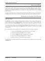
AUTOMATED FACTORY-SELF TEST PROGRAM
Self-Test Mode
The FX-Maxx software contains a self-test program to facilitate factory testing of the entire airconditioning system. Once the self-test mode is activated, the test cycle will continue until the AC
power is interrupted or the on/off button is pressed once which returns the system to the off mode.
Activate the self-test by pressing and holding the on/off button while turning on the AC power. Be
sure to continue to hold the button until the power on reset is completed… FX-Maxx is now in the
self-test mode.
Once activated the self-test software will continuously execute the following procedure:
1 - Turn on in the heat mode and supply heating for ten (10) minutes.
2 - Stop heating and run the fan only for five (5) minutes.
3 - Switch to cooling and continue cooling for ten (10) minutes.
4 - Stop cooling and run the fan only for five (5) minutes.
5 - Return to step one (1) and continue until interrupted.
The test mode will continue until the power is interrupted or the test is halted by pressing the on/
off button once.
Revision: 06
04 / 08 / 09
Page 16
FX-Maxx Operations Manual
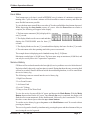
SERVICE TOOLS
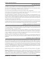
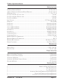
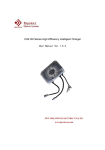
Hour Meter
Total compressor cycle time is saved in EEPROM every 6 minutes of continuous compressor
running time. Cycles less than 6 minutes will be discarded to conserve memory and allow the
most flexible hour-meter possible.
To view the hour meter turn off the power at the AC breaker and hold the down button depressed.
While depressing the down button, restore AC power. After the Power-On reset routine is
complete, the following will appear in the display:
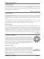
1. The hour meter mnemonic [Hr] is displayed for
one [1] second.
2. The display blanks out for one second and then
displays the THOUSANDS units for three [3]
seconds.
3. The display blanks out for one [1] second and then displays the hours for three [3] seconds.
4. The unit returns to the last operating state before power was removed.
The example shown is displaying twelve-hundred twenty-four [1,124] hours.
Maximum recorded time is 10,000 hours. The hour meter stops at maximum (10,000 hrs) and
can only be reset by Micro Air Corporation Corporation.
Service History
FX-Maxx will record and remember the last eight (8) service problems or service faults detected.
Each time a fault is detected, a one hour timer is started. During that hour the same recurring fault
will not be recorded. Should a different fault be detected during that hour, it will be entered into
the service history log.
The following events are entered into the service history log:
1. High Freon Pressure
2. Low Freon Pressure
3. Air Sensor Fault
4. Low AC Voltage
5. Pump or Loss of Sea Water Fault
To view the service log turn off the AC power and depress the Mode Button. With the Mode
Button depressed turn on the AC power. Once Power-On reset is completed, the display will
flash the most recent mnemonic for the fault detected, followed by the event number. To view
the other events detected press either the up or down buttons.
To exit the service history log press the power or the Mode Button or wait 30 seconds without
pressing any buttons.
The service log can be cleared by simultaneously pressing the power and down buttons while you
are viewing the service log mode.
Revision: 06
04 / 08 / 09
Page 17
FX-Maxx Operations Manual
Revision: 06
04 / 08 / 09
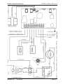
FX-MAXX WIRING DIAGRAM
Page 18
FX-Maxx Operations Manual
Revision: 06
04 / 08 / 09
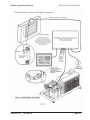
INSTALLATION OVERVIEW
Page 19