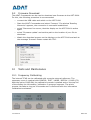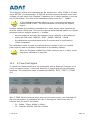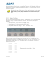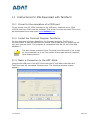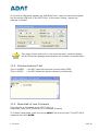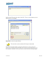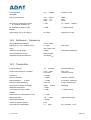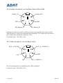
1
Operating Manual
For Software Defined Radio ADT-200A
SW-Version 1.35
13.10.2010
Seite 1
13.10.2010
Seite 2
Congratulation,
You have acquired an ADAT ADT-200A. The device is equipped with the latest
DSP technology; moreover it is produced professionally with state-of-the-art
technology.
Special care has been taken to bring today’s possibilities of digital signal
processing truly from the aerial to the loudspeaker. The result is a device which
shows the quality of a measurement device to some extent. Hence, the ADT200A is especially suited very well for technically interested amateurs.
Due to the software-based technology, firmware updates can be downloaded to
the ADT-200A which enables new functions. The present version 1.35 is an
intermediate step in an on-going development.
Notice:
This device must be operated only by radio amateurs with a suitable license. For
problems which originate from the improper usage of the ADT-200A, every
liability is declined. The disclaimer of liability is also valid for security-relevant
applications, as for example in a catastrophe network.
Please read this manual carefully, in particular the chapter „Read this first“,
which contains important tips for the safe and law-compliant usage.
13.10.2010
Seite 3
Content
1 General informations .................................................................................................7
2 Read this first ...............................................................................................................8
2.1 Used Standards .....................................................................................................8
2.2 Compatibility to EU directives ............................................................................8
2.3 Notes on Disposal .................................................................................................9
2.4 Precautions.............................................................................................................9
3 Installation ..................................................................................................................10
3.1 Power Supply .......................................................................................................10
3.1.1 Line Power..................................................................................................10
3.1.2 Operational Ground..................................................................................10
3.1.3 Battery Operation .....................................................................................10
3.1.4 Air Flow.......................................................................................................10
3.2 Connections on the back side ..........................................................................11
4 Operation......................................................................................................................12
4.1 Controls on the Front .........................................................................................12
4.2 Menu Structure....................................................................................................13
4.2.1 Function Keys ............................................................................................13
4.2.2 Menu Keys..................................................................................................14
4.3 Details on the Main Menu..................................................................................14
4.3.1 BAND Selection (F1)....................................................................................14
4.3.2 Operation Mode Selection, MODE (F2).................................................15
4.3.3 Filter Bandwidth Selection, FILTER (F3) ..............................................15
4.3.4 Selection OPTION (F4) ............................................................................15
4.4 The VFO-Concept ................................................................................................16
4.4.1 General .......................................................................................................16
4.4.2 Configuration of the VFO’s......................................................................17
4.4.3 Simultaneous Operation of multiple VFO’s..........................................17
4.4.4 Split-Operation..........................................................................................17
5 Operation Modes........................................................................................................19
5.1 CW Reception ......................................................................................................19
5.1.1 Sideband Selection...................................................................................19
5.1.2 Setting the Rx-Bandwidth.......................................................................19
5.1.3 Beat Frequency Oscillator BFO ..............................................................20
5.1.4 Automatic Fine Tuning.............................................................................20
5.1.5 CW Peak Filter ...........................................................................................20
5.1.6 Mode specific settings..............................................................................20
5.2 Transmit in CW....................................................................................................21
5.2.1 Adjusting the Output Power ...................................................................21
5.2.2 Transmission .............................................................................................21
5.2.3 Mode specific settings..............................................................................22
5.3 SSB-Reception.....................................................................................................22
5.3.1 Selection of Sideband ..............................................................................22
13.10.2010
Seite 4
5.4
5.5
5.6
5.7
5.8
5.3.2 Setting the Receiver Bandwidth ............................................................23
5.3.3 Mode Specific Settings ............................................................................24
5.3.4 Pass Band Tuning .....................................................................................24
5.3.5 Equalizer.....................................................................................................24
5.3.6 Notch Filter ................................................................................................25
5.3.7 Selection of Rx Antenna..........................................................................25
Transmit in SSB ..................................................................................................25
5.4.1 Output Power adjustment.......................................................................25
5.4.2 Audio Source Selection............................................................................26
5.4.3 Microphone Gain Setting.........................................................................26
5.4.4 Transmit Filter Selection .........................................................................27
5.4.5 Equalizer.....................................................................................................27
5.4.6 Modulation Monitoring .............................................................................27
5.4.7 Power Enhancer ........................................................................................27
5.4.8 Tune Function............................................................................................28
AM Reception.......................................................................................................29
5.5.1 AM Filters ...................................................................................................29
5.5.2 Function F-TUNE .......................................................................................29
5.5.3 Function DEMOD.......................................................................................30
5.5.4 Function N-5kHz .......................................................................................30
Transmit in AM ....................................................................................................30
5.6.1 Transmit Power Adjustment...................................................................30
FM Reception .......................................................................................................31
5.7.1 FM Filters....................................................................................................31
5.7.2 Mode Specific Settings ............................................................................31
Transmit in FM.....................................................................................................33
6 Other Functions .........................................................................................................34
6.1 Frequency Tuning ...............................................................................................34
6.2 Preamplifier and Attenuator .............................................................................35
6.3 Automatic Gain Control, AGC ...........................................................................36
6.4 S-Meter .................................................................................................................37
6.5 Power and SWR Meter .......................................................................................38
6.6 Noise Blanker.......................................................................................................39
6.7 Notch Filter...........................................................................................................39
6.8 Clarifier .................................................................................................................39
6.9 Selection of the Audio Source ..........................................................................40
6.10 The VOX................................................................................................................41
6.11 Control of an Automatic Antenna Tuner ........................................................42
6.12 Control an external PA.......................................................................................43
6.13 Antenna Selection...............................................................................................44
6.14 External Frequency Reference .........................................................................44
6.15 Preselector PSL2 .................................................................................................45
7 Memories ......................................................................................................................47
8 System Functions ......................................................................................................49
8.1 Data Bases ...........................................................................................................49
8.2 Personality File ....................................................................................................50
13.10.2010
Seite 5
8.3
Options..................................................................................................................50
9 ADAT Controller .........................................................................................................51
9.1 Installation ...........................................................................................................52
9.2 Firmware Download............................................................................................53
10 Tests and Maintenance ...........................................................................................53
10.1 Frequency Calibrating ........................................................................................53
10.2 2-Tone Test Signal .............................................................................................54
10.3 Scan-Function......................................................................................................55
10.4 PA Monitor-Functions .........................................................................................56
10.5 Calibration of the Preselector PSL2.................................................................56
11 Instructions for SW-Download with TeraTerm .............................................57
11.1 Driver for the emulation of a COM-port .........................................................57
11.2 Install the Terminal Program TeraTerm.........................................................57
11.3 Make a Connection to the ADT-200A..............................................................57
11.4 Communications Test.........................................................................................58
11.5 Download of new Firmware ..............................................................................58
12 Specifications..............................................................................................................61
12.1 Receiver ................................................................................................................61
12.2 Reference - Frequency.......................................................................................62
12.3 Transmitter ..........................................................................................................62
12.4 General Data........................................................................................................63
13 Annex 1, Pinout Diagrams .....................................................................................64
13.1 Microphone-Connector on the Front ...............................................................64
13.2 Connections for an ICOM Microphone (e.g. SM-20) ....................................64
13.3 Connections for an YAESU Microphone ..........................................................65
13.4 Morse Key.............................................................................................................65
13.5 Morse Paddle........................................................................................................65
13.6 Audio Connector on the Back Panel (Mini-DIN)............................................66
13.7 Data Connector on the Back Panel..................................................................66
13.10.2010
Seite 6
1 General Information
Declaration of Conformity
ADT-200A
The undersigned hereby declares that the above-referenced product, to
which this declaration relates, is in conformity with the provisions of:
2004/108/EC
Directive on Electromagnetic Compatibility;
2006/95/EC
Directive on Low Voltage Equipment Safety;
1999 / 5 / EG
Directive on Radio and Telecommunication Terminal
Equipment
2002 / 95 EG
RoHS-Directive
The product has been validated according the following standards:
EN
EN
EN
EN
EN
301 783-1 V1.1.1 (2000-09),
301 783-2 V1.1.1 (2000-09),
301 489-1 V1.4.1 (2002-08),
301 489-15 V1.4.1 (2002-08),
60950 (August 1994)
Manufacturer:
Ingenieurbuero
Hans Zahnd
Bauche 134b
3543 Emmenmatt
Switzerland
Tel: 0041 402 34 87 71
Emmenmatt, 12. Oktober 2009
13.10.2010
Seite 7
2
Read this first
2.1
Used Standards
o
EN 301 783
V1.1.1 (200009)
Electromagnetic compatibility and Radio Spectrum
Matters (ERM);
Commercially available amateur radio equipment;
Parts 1 + 2
o
EN 301 489
V1.4.1 (200208)
Electro Magnetic compatibility and Radio spectrum
Matters (ERM);
Electro Magnetic Compatibility (EMC) standard for
radio equipment and services;
Part 1:
Common technical requirements
Part 15: Specific conditions for commercially
available amateur radio equipment
o
EN 50081-1
Electromagnetic compatibility – Generic emission
standard
o
EN 50082-1
Electromagnetic compatibility – Generic immunity
standard
o
EN 55022
Limits and methods of measurement of radio
disturbance characteristics of information
technology
o
EN 60950
Information technology equipment - Safety
2.2
Compatibility to EU directives
o
2004 / 108 / EG
EMC Directive
o
2006 / 95 / EG
Low Voltage Directive
o
1999 / 5 / EG
Richtlinie über Funkanlagen und TelekomEndeinrichtungen (German)
o
2002 / 95 EG
RoHs Directive
o
2002 / 96 / EG
Entsorgung von Elektronik-Altgeräten (German)
13.10.2010
Seite 8
2.3
Notes on Disposal
o
Remove the battery and dispose it separately
o
All housing and chassis parts are made of aluminum and are bolted. They
can be completely recycled.
o
The power transistors mounted on the heat sink contain beryllium oxide
and must be disposed separately.
o
The electronic components are RoHS compliant (lead free) and can be
disposed accordingly.
2.4 Precautions
Always disconnect the line voltage before you open
the enclosure, as there are dangerous voltages
inside.
Do not plug the ear phones into the loudspeaker jack,
as this could damage your ears.
The Transceiver shall only be powered by a 3-pol line
cable with a protective ground for safety.
Use only fuses 3.15AT (slow blow) for replacement.
An operation ground is needed for transmit operation.
Do not obstruct the air flow from the internal
ventilator.
The transceiver must be protected against humidity,
when operated outside.
It is recommended to switch off the main switch on
the rear side if the device is not used for a longer
time.
13.10.2010
Seite 9
3
Installation
3.1
Power Supply
3.1.1 Line Power
The power supply accepts line AC voltages from 90V up to 240V. The ADT-200A
must always be connected to a protective ground.
The main switch is on the rear side. If it is on, the internal AC/DC converter is
running and the LED ‘standby’ on the front is lit.
3.1.2 Operational Ground
To prevent a feed back of RF currents to the line system, the transceiver must
be connected to an operative ground.
3.1.3 Battery Operation
For battery operation an external DC/AC converter for 220V, 150W is needed.
3.1.4 Air Flow
The internal ventilator aspirates the air from the bottom side of the housing and
blows it out on the top and rear side. Take care for a free circulation.
13.10.2010
Seite 10
3.2 Connections on the back side
1
2
3
11
4
5
12
6
13
7
14
8
15
16
9
17
18
19
20
1
Line Out: Audio Signal to PC Sound Card
11
Separate Rx-Antenna for 0.01…30MHz
2
Line In: for signals from PC Sound Card
12
Rx-In: to be connected with Rx Out (7)
3
Reset for Restart of DSP-Module
13
Audio-I/O and Control to Linear-Amplifier
4
Input for ext. Frequency Reference (>0dBm)
14
Ethernet 10/100 BaseT for Web-Module
5
Auxiliary connector to external controls
15
Data-I/O, to connect a PS2 PC-Keyboard
6
USB Connector for communication with a
PC
16
Output for Loudspeaker 4/8Ω, Channel B
17
Input for Key or Paddle
7
Rx-Signal: must be connected to Rx In (12)
18
Output for Loudspeaker 4/8Ω, Channel A
8
Rx/Tx-Antenna 1
19
Line In, 3-pol, 115 / 230Vac
9
Rx/Tx-Antenna 2
20
Main Switch
10
Monitor-Input from external Linear Amplifier
21
Connection for Operating Ground
13.10.2010
10
21
Seite 11
4
Operation
4.1
Controls on the Front
S-Meter and
Power-Meter
Tuning Step
selection
Menu-Keys
Microphone
Function Keys
SELECT-Knob
AF-Gain
Tuning Knob
On/Off-Key
(Off = Standby)
A pinout drawing of the microphone connector can be found in Annex A.
13.10.2010
Seite 12
4.2
Menu Structure
4.2.1 Function Keys
Many commands may be entered by the Function Keys F1 to F5 (Soft Keys).
Submenu available
with SELECT-Knob selectable Option
Function
Function Key
Selection of an Option (e.g. MODE):
1. Press the Key below the Function (the Function appears now inverse)
2. Turn the SELECT knob for the desired option
3. Push the Select knob for save, or press the same function key again
Some of the functions execute the command immediately, such as the filter
bandwidth or the output power. The new parameter is activated without saving it
first.
Functions with a ▼ have a submenu for further selections. The BACK key will
always guide you back one step until you reach again the Main Menu.
13.10.2010
Seite 13
4.2.2 Menu Keys
MEMORY: opens a Menu to handle the 100 memory cells
CONFIG: Handles all configuration parameters
CLARIF:
Clarifier ± 9.999kHz for Rx-Frequency
EXTRAS: Will be used later for special functions
BACK:
Leads back to the main menu
NOISE:
On/Off for the Noise-Blankers
NOTCH:
Automatic Notch Filter
MOX:
‚Manually Operated Xmitter’ to operate the
transmitter (for CW- or VOX-operation)
F-TUNE: used for automatic tuning at AM/CW
RECORD: Will be used later for the audio-recorder
4.3
Details on the Main Menu
4.3.1 BAND Selection (F1)
For a quick selection, the full reception range between 10 kHz and 30 MHz is
divided into different utility bands:
o
WIDE
-> general coverage
o
HAM
-> Amateur Bands 1.8 … 29.7MHz
o
BRCST -> Broadcast Bands 3.9…26MHz
Function WIDE
With the SELECT button the desired frequency can be roughly selected in steps
of 1 MHz and then fine-tuned with the tuning knob in the area of 10 kHz to 30
MHz.
Function HAM
With this function one of the amateur radio bands between 160 m and 10 m can
be selected. When changing the band the frequency of the previous band is
stored. The bands are limited to 50 kHz beyond the band limits.
Function Broadcast, BRC
A broadcasting band can be quickly discovered with the function BRC. In contrast
to HAM the broadcasting bands BRC are not band limited. When changing the
band the frequency of the previous band is stored.
13.10.2010
Seite 14
4.3.2
Operation Mode Selection, MODE (F2)
The following operation modes are selectable by MODE:
o
CW-R
CW reverse (equivalent to LSB-Mode)
o
CW
CW normal
o
LSB
SSB, lower sideband
o
USB
SSB, upper sideband
o
SSB
automatic sideband choice depending on the selected band
o
AM
AM with Envelope-Demodulator
o
AM-SL
AM synchronous, lower sideband *)
o
AM-SU
AM synchronous, upper sideband *)
o
FM
Frequency Modulation
*) not yet implemented
4.3.3
Filter Bandwidth Selection, FILTER (F3)
The filter ranges are different for the modes of operation CW, SSB, AM and FM.
The filter tables are showed in the following chapters.
4.3.4
Selection OPTION (F4)
The Function OPTION has several submenus as discussed below:
13.10.2010
Seite 15
o
With the functional key F1, a submenu opens for settings of the AGC:
o
With the functional keys F2 and F3, the Attenuator and the Preamplifier
are set.
These both functions compensate each other: 5dB Attenuator and
5dB Preamplifier have the same effect as setting them both to 0dB.
o
4.4
Under the function M-SPEC (F4) Mode-specific menus are available. The
operation is explained in the relevant sections of the operating modes.
M-SPEC menus exist for the operating modes CW, SSB, AM and FM.
The VFO-Concept
4.4.1 General
o
To each of the four channels one Rx- and one Tx-VFO are assigned.
Therefore, there is a total of 8 VFO's.
o
Every channel has its own data base, i.e. all adjustable parameters are
assigned to every channel individually.
o
Several VFO's may be switched on at the same time.
o
The selection of a specific VFO occurs by pressing once on the respective
functional key in the VFO menu. All parameters and frequencies are
thereby switched and this VFO becomes the active channel.
o
The frequency of the active channel is indicated in the display at the top
frequency line in big numbers, the frequency of the other channels is
displayed below, sorted by channel number.
o
Frequency, band and mode of operation of the transmitter can be
configured in the VFO-Menu arbitrarily. This enables cross band operation.
13.10.2010
Seite 16
4.4.2 Configuration of the VFO’s
Selection OFF
The function OFF switches the currently active VFO off. The frequency display of
this channel is cleared. After this operation another channel must be chosen.
Selection ON
With the function ON a channel is switched on. All parameters previously stored
are restored and made active.
Selection SET
With the function SET the frequency and the operation mode of the transmitter
can be configured independently of the receiver. Any combination of frequency
and modulation settings is possible. This function is intended to use for cross
band operation on the VHF bands.
4.4.3 Simultaneous Operation of multiple VFO’s
The transceivers up to serial number 0903050 are equipped with the preselector
PSM1B. This allows simultaneous operation on multiple bands, as all required
half octave filters are turned on. But it has the disadvantage that the preselector
loses part of its selectivity.
The new preselector PSL2A is provided by default on all units from serial number
1004051 upwards. It is much more selective than the PSM1B and therefore
allows receiving only within one band. For special cases, if simultaneous
operation on several bands is required, two high-pass filters can be inserted
manually.
4.4.4 Split-Operation
The split operation has been completely reworked as of firmware version 1.35.
This mode is now running in a separate configuration set with its own databases.
This ensures that all settings remain in the memory after leaving the split
operation. In this mode, two VFO (A and B) settings are synchronized against
each other, except the parameters ‘Filters' and 'Volume'. The other parameter
settings apply always to both channels, regardless of whether they have been
made in Channel A or B.
13.10.2010
Seite 17
The frequencies of A and B are each presented on the display with large figures.
Basically, the channel A is only used for reception (Rx1), while the channel B is
dedicated to receive and transmit (Tx1). The currently selected channel is
marked with an arrow. Its frequency can be changed with the frequency tuning
knob.
The Split-Menu allows the following operations:
o
F1 CH A
A = Rx
A=B
o
F2 CH B
B = Tx
B=A
A is receiving on the frequency showed on the
upper line
The frequency of B is assigned to A
B is receiving on the frequency showed on the
lower line
The frequency of A is assigned to B
o
F3 DUAL-W
Dual Watch: both channels A and B are received
simultaneously and are audible on the head phones (A →
left, B →right) or the loudspeakers (A → LS A and B → LS
B).
o
F4 REVERS
If ON, the channels A and B are interchanged.
For the units up to serial number 0903050 both channels are
connected to both loudspeakers
13.10.2010
Seite 18
Function
VFO-A (upper)
Rx
Tx
VFO-B (lower)
Rx
Tx
CH-A: A=Rx
A
B
B
B
CH-A: A=B
B
B
B
B
CH-B: B=Tx
A
B
B
B
CH-B: B=A
A
B
A
A
Dual Watch
A
B
B
B
REVERS OFF
A
B
B
B
REVERS ON
B
A
A
A
5
Operation Modes
5.1
CW Reception
5.1.1 Sideband Selection
With the function MODE = CW or CW-R the CW operation mode is switched on.
The CW setting corresponds to USB reception; this means that the beat
frequency of a station appears with a falling beat tone with increasing frequency.
The setting CW-R corresponds to LSB reception where increasing frequency
results in a rising beat tone. The choice of the sideband is a matter of practice.
5.1.2
Setting the Rx-Bandwidth
For CW reception, 10 filters with a bandwidth range of 50 Hz to 1200 Hz are
available. They can be selected with the function FILTER.
B
(-6dB)
B
(-60dB)
Shape-Factor
[B-60dB / B-6dB]
Signal Delay
[ms]
[Hz]
[Hz]
50
148
2.960
44
75
171
2.280
44
100
196
1.960
44
150
246
1.640
44
200
392
1.960
28
300
492
1.640
28
500
692
1.384
28
700
892
1.274
28
1000
1192
1.192
20
1200
1392
1.160
20
*) signal delay applies for the entire receiver
13.10.2010
Seite 19
5.1.3
Beat Frequency Oscillator BFO
The frequency of the CW tone can be configured with OPTION / M-SPEC / BFO.
The available range covers 300 Hz to 1000 Hz in steps of 50 Hz. This setting has
no influence on the Rx frequency.
5.1.4
Automatic Fine Tuning
The frequency offset of a CW signal is indicated by an arrow and related to the
bandwidth of the used filter.
The right and left limits correspond to
the -3dB frequencies of the selected
filter. When the arrow is in the middle,
the Rx and Tx frequencies are adjusted
exactly to the remote station.
Moreover, the fine tuning to a CW signal is done automatically by pressing the
F-TUNE key once. The green LED (locked) is blinking during the tuning process
and is illuminated permanently when the signal is locked. In this state, the
frequency remains fixed, until the frequency knob is moved. It will not follow
further on to an unstable frequency.
5.1.5
CW Peak Filter
As the use of the notch filter in the mode of CW make no sense, its function is
inverted at CW. Thus we have an automatic peak filter with the ability to self
align to any carrier(s) within the receive filter. This filter reduces the noise to
some extend. It is most reliable at the largest bandwidths (1200Hz) and can
increase the signal to noise by up to 6dB at weak signals.
5.1.6
o
Mode specific settings
F1 BFO:
13.10.2010
Adjustment of BFO frequency in the range of 300 …
1000Hz in steps of 50Hz
Seite 20
o
F2 KEYER:
STNDRD: standard key,
IAMBIC: left Paddle: dot; right Paddle: dash
IAMB-R: left Paddle: dash; right Paddle: dot
o
F3 SPEED:
speed adjustment for Iambic Keyer, range 6 … 40
words/min.
o
F4 TxTONE:
frequency of Tx side tone (as BFO, or adjustable in the
range of 300…1000Hz in steps of 50Hz independent of
BFO
o
F5 MORE:
the button F5 gets another submenu with additional
functions (see section 5.2.3)
The current version is implemented without dash and dot memory.
An implementation to approximate the Curtis-Keyer is in
preparation.
5.2
Transmit in CW
The impulse form of the CW signals is shaped by a Blackman-Harris function.
This technique stands out due to click-free signals and an extremely narrow
transmission spectrum.
5.2.1
Adjusting the Output Power
The output power is configured the same way as in SSB mode, via CONFIG / TX
/ POWER.
5.2.2
Transmission
Before starting a transmission, the MOX key must be pressed. The LED "on air"
is blinking until the Morse key is pressed down.
MOX
on
off
LED on air
Key
Mode
on
off
on
off
Tx
Rx
Delay
13.10.2010
Seite 21
When transmitting, i.e. if the LED "on air" is permanently on, the
frequency remains locked and can be changed only when back in the
Rx operation.
5.2.3
Mode specific settings
Some additional mode specific settings are available under MORE:
o
5.3
F1 QSK:
The selection between semi- und full-break-in is possible by
means of the button F1:
o
SMI-BK: normal operation. This setting is also suitable
to serve an external power amplifier
o
FUL-BK: the switching time from Tx to Rx is as low as
35ms (filter ≥ 1000Hz). This timing is too fast for an
external power amplifier!
o
F2 DELAY
The value, selected under DELAY determines the hold time
for the transmitter, i.e. the time after the last sign until
switching over into the reception mode.
o
F3 DECODE
The function DECODE is reserved for a CW-decoder (not
available yet).
SSB-Reception
5.3.1 Selection of Sideband
In SSB operation, there are three MODE settings available:
o
LSB: lower side band, commonly on HAM bands less than 8 MHz
o
USB: upper side band, commonly on HAM bands above 8 MHz
o
SSB: automatic selection according the HAM band
13.10.2010
Seite 22
LSB
USB
f
f
Position of the suppressed carrier
( = displayed Frequency)
To receive a carrier signal with a heterodyne tone of 1 kHz, the RX frequency
must be configured 1 kHz higher in LSB mode and 1 kHz lower in USB mode
than the carrier frequency.
5.3.2
Setting the Receiver Bandwidth
In SSB mode, there are 13 filters with a bandwidth range of 300Hz to 3.5kHz
available. They can be selected with the function FILTER.
[Hz]
[Hz]
fu
[Hz]
fo
[Hz]
Shape-Factor
[B-60dB / B-6dB]
Signal Delay
[ms] *)
300
688
850
1150
2.293
20
500
888
750
1250
1.776
20
700
1088
650
1350
1.554
20
1000
1384
420
1420
1.384
20
1200
1588
330
1530
1.323
20
1500
1884
280
1780
1.256
20
1800
2186
245
2045
1.214
20
2000
2386
225
2225
1.193
20
2200
2584
210
2410
1.175
20
2400
3168
195
2595
1.320
12
2700
3472
175
2875
1.286
12
3000
3776
160
3160
1.259
12
3500
4272
140
3640
1.221
12
B
(-6dB)
B
(-60dB)
*) signal delay applies for the entire receiver
The filters from B ≥1200Hz are optimized for best intelligibility. The resulting
product is fu * fo ≈ 500'000 (PBT = 0Hz). On the other hand, the centre
frequency of filters up to B ≤ 1000 Hz is set on 1 kHz, which is favorable for
digital operation modes.
13.10.2010
Seite 23
5.3.3
Mode Specific Settings
5.3.4
Pass Band Tuning
Pass Band Tuning (PBT) permits the movement of a filter pass band on the
frequency axis. With this, the sound of the receiver and in particular the lower
cut off frequency of the received signal can be changed in wide borders. Besides,
this function allows fading out a disturber in a strong QRM.
Pass Band Tuning can be used only in SSB mode under the OPTION / M-SPEC /
PBT. The PBT range spans from -200Hz to +500Hz in steps of 50Hz.
LSB
USB
green: -200Hz
blue:
red:
0Hz
+200Hz
f
f
Position of the suppressed carrier
( = displayed Frequency)
5.3.5 Equalizer
The 3-channel equalizer can be configured in the menu OPTION / M-SPEC. The
centre frequency is 100Hz, 550Hz and 3000Hz. These filters can be changed with
the functions EQ-LOW, EQ-MID and EQ-HIGH in the range of -18dB to +18dB in
steps of 3dB.
The functions FILTER and PBT may degrade the effectiveness of the
equalizer.
13.10.2010
Seite 24
dB
+18
+9
0
-9
-18
100
550
3000 Hz
5.3.6 Notch Filter
The Notch Filter is realized by an adaptive LMS algorithm and is able to filter one
or several CW carriers out of the received signal. It can be switched on and off
with the NOTCH button. The status is indicated in the big display in the status
column. The depth of the notch is 60dB.
5.3.7 Selection of Rx Antenna
With the function CONFIG / RX, the antenna can be selected as follows:
o
as TX: the input Rx In is activated. Rx In is ordinarily connected with the
port Rx Out from the transmitter module PAM over a coaxial cable.
Instead of the direct connection an external preselector may be inserted.
o
RX-ANT: serves for the connection of a separate reception antenna. This
input is protected against over voltage. Hence, use only this input for the
connection of Rx outdoor aerials.
5.4
Transmit in SSB
5.4.1 Output Power adjustment
With the function CONFIG / TX / POWER the transmit power can be set in 16
steps in the range of 0.1 W to 50 W. All adjustable power levels have been
calibrated at the factory for every band with a 2-tone modulation. With speech
modulation, an overshoot of about 10% is possible. The selected output power is
maintained, independently of the input signal.
13.10.2010
Seite 25
Reasons which lead to a reduction of the transmit power:
o
The MIC GAIN is too low.
o
A high SWR, greater than 1:2. Note that an impedance of 25 Ω
corresponds to an SWR of 1:2. If the output voltage in the transmitter was
held constant, it would have to deliver 100 W. On the other hand an
impedance of 100 Ω (SWR also 1:2) is no problem for the output stage.
o
If the peak value of the envelope cannot be regulated completely by the
predistortion.
o
If the supply current of the output stage rises up to > 2.8A.
While the transmission, the frequency remains locked and can be
changed only in Rx mode.
5.4.2 Audio Source Selection
The audio source can be chosen in the menu CONFIG / Tx / AUDIO / SOURCE.
There are following possibilities:
•
LINE IN: Input on the rear side (3.5 mm jack connector) for the
connection of a PC for digital operation modes.
•
MIC-ELE: Connect an electret microphone to the connector MICRO on the
front panel. There is a supply voltage of 2.5 V, 2 mA between the Pins
MIC-In and MIC-GND. An additional pin carries 7.5 V for microphones with
a higher voltage requirement (e.g., Icom and others).
•
MIC DYN: for the connection of a dynamic microphone. Here the NF signal
is additionally amplified with a preamplifier of 20dB.
Line In
Audio Codec
ELE
20dB
MICRO
DYN
2.5V
5.4.3 Microphone Gain Setting
With the function CONFIG / TX / AUDIO / MIC-GAIN the modulation magnitude
of the transmitter can be determined in the range of -30dB to +18dB in steps of
6dB. Basically the transmitter cannot be over-modulated. However, a too high
setting has the disadvantage that the ALC is increasing the gain in speech breaks
unnecessarily high and thus is producing annoying background noise.
13.10.2010
Seite 26
To get the best microphone gain setting, use the following procedure:
•
Speak with normal loudness into the microphone
•
Increase the MIC-GAIN beginning from -30dB gradually until the value of
the output power corresponds to the selected power. Increasing the gain
further does not increase the transmit power.
5.4.4 Transmit Filter Selection
The NF bandwidth of the transmitter can be adjusted with the function CONFIG /
TX / AUDIO / FILTER. For the lower cutoff frequency, either 200 Hz or 300 Hz
can be selected. For the upper cutoff frequency, 2400 Hz, 2400 Hz, 2700 Hz and
3000 Hz are available.
Follow the local license terms concerning the maximum NF range (in
many countries the maximum allowed bandwidth is 2700 Hz).
5.4.5 Equalizer
In the NF path of the transmit signal there is an equalizer with the same qualities
as the equalizer in the receiver path. It allows filtering the modulation signal
according to your own wishes.
5.4.6 Modulation Monitoring
The transmit signal is fed back from the output to the receiver for the control of
the adaptive predistortion. This signal is a true monitor signal and can be used
for controlling purposes, for example to record different settings of the Tx
equalizer by the soundcard of a PC. A connection from the ADT-200A’s Line Out
to the Line In of the PC is required to do that.
The volume of the monitor signal can be adjusted with the AF-GAIN during
transmitting. This setting has no influence on the Rx volume.
If a loudspeaker is connected, acoustic feedback to the microphone
can occur when the volume is too high.
5.4.7 Power Enhancer
The Power Enhancer has been developed as an alternative to the conventional
speech compressors. The envelope is regulated depending of the modulation
instead of clipping the amplitude. This regulation is comparable with a change of
the volume and, hence, free of distortion.
13.10.2010
Seite 27
Output [dB]
10
0
linear
-10
3dB
6dB
9dB
-20
12db
-30
-40
-50
-50
-40
-30
-20
-10
0
Input [dB]
The characteristic of the Power Enhancer consists of a compressing, a linear and
a decompressing part. The latter should suppress the ambient noise. With this
technique, middle amplitudes can be increased by 3dB to 12dB which results in a
more efficient modulation.
The Power Enhancer can be found at CONFIG / TX / P-ENH.
When operating with unnecessary high MIC-GAIN, the Power Enhancer
loses its efficiency.
5.4.8 Tune Function
The Tune Function serves for the generation of a carrier signal, mainly for
antenna tuning. This function can be activated by the F-TUNE button, when MOX
is on.
The adjustment of the carrier power is to find under CONFIG / TX / MORE /
MORE / TUNE and is configurable between 0.1W and 50W in 16 steps.
The frequency of this carrier is adjusted to the (suppressed) SSB carrier. This
allows retuning the antenna without disturbance of an ongoing QSO.
To switch off the carrier signal, simply press the key MOX again.
Use the smallest possible power to tune your antenna. The built-in
SWR meter works well with 100mW.
13.10.2010
Seite 28
5.5
AM Reception
The ADT-200A is equipped with a highly linear envelope demodulator. Together
with the brick wall filters it offers a good solution for many receiving situations.
5.5.1 AM Filters
For AM reception there are 10 filters in the range of 3 kHz to 10 kHz available.
These can be selected by the function FILTER.
B
[Hz]
[Hz]
Ripple
[±dB]
Shape-Factor
[B-0.2dB / B-80dB]
3000
4000
0.2
1.333
3500
4500
0.2
1.286
4000
5000
0.2
1.250
4500
5500
0.2
1.222
5000
6000
0.2
1.200
6000
7000
0.2
1.167
7000
8000
0.2
1.143
8000
9000
0.2
1.125
9000
10000
0.2
1.111
10000
11000
0.2
1.100
(-0.2dB)
B
(-80dB)
5.5.2 Function F-TUNE
If the F-TUNE key is pressed during AM reception, the receiver is exactly tuned
to the carrier of the received station during 5 seconds. The LED “locked” blinks
while the fine-tuning is in progress. After 5 seconds, the control process is
stopped and the LED remains on until the frequency is changed with the tuning
knob.
The precision of this AFC function is ±1Hz and is suitable for the SSB reception
of an AM transmitter (with LSB or USB). This function can also be used to
determine the frequency calibration offset of the ADT-200A, for instance with the
transmitter WWV (10 MHz).
With strong fading, the carrier may be attenuated and the algorithm
is no more able to lock.
13.10.2010
Seite 29
5.5.3 Function DEMOD
The function DEMOD in the menu OPTION / M-SPEC is planned for the choice
between envelope and synchronous demodulator. A synchronous demodulator is
in preparation and will be configured with the functions AM-SL and AM-SU.
5.5.4 Function N-5kHz
The function N-5kHz in the menu OPTION / M-SPEC makes available a narrow
5 kHz notch filter which suppresses the unpleasant interference tone while
tuning. This happens when the carriers of two neighboring stations are both in
the pass band.
dB
-20
-40
-60
-80
1.0
3.0
5.0
7.0
9.0
kHz
The above figure shows the noise spectrum from AM demodulator when the 5kHz
notch filter is switched on.
Hints for the AM reception with the demodulator: after the frequency
fine tuning with the F-TUNE function, you may switch over to SSB
reception. This mode has the big advantage, that there are no
distortions due to selective fading.
Furthermore, at B = 3500Hz and PBT = -200Hz, you will profit from
a better AGC regulation, as now the AM carrier falls within the filter.
5.6
Transmit in AM
5.6.1 Transmit Power Adjustment
The transceiver is equipped with a high linear modulator for AM. It is capable to
transmit a peak power of 50Wpep. Please respect that, in contrast to SSB, the
setting under POWER relates to the power of the unmodulated carrier.
13.10.2010
Seite 30
When the carrier
amplitude is adjusted
to 1.0 and the
modulation factor is
set to 90% then the
modulated output
signal varies between
0.1 and 1.9. The peak
power is therefore 1.92
= 3.61 times higher
than the carrier power.
As the peak power is max. 3.61 times higher than the carrier power, the selected
power setting under CONFIG / Tx / POWER should be selected less than or equal
to 15W.
The adjustments for the Tx equalizer and the transmit filter can also be used for
the AM mode.
5.7
FM Reception
5.7.1 FM Filters
5 filters with ranges of 6 kHz to 10 kHz are available for FM reception. Their
properties correspond to the AM filters. Other filters with ranges up to 25 kHz
are planned for applications in the VHF bands.
5.7.2 Mode Specific Settings
The access to the mode specific settings starts at the main menu via OPTION /
M-SPEC.
o F1 SQLCH
13.10.2010
The Squelch threshold can be set in the range of -116 …
Seite 31
-60dBm (0.35 µV … 223 µV) in steps of 2dB. The setting
occurs with OPTION / M-SPEC / SQLCH (F1). In order to
switch off the Squelch, rotate the Select knob over the
-116dBm position until OFF appears.
o
F2 DEEMP
To improve the signal to noise ratio, the frequency
response of the transmitter is preequalized by increasing
high audio frequencies (preemphasis). This permits to
lowering high frequencies in the receiver by the same
amount. As a result, by the postequalizing in the receiver
(deemphasis), a reduction of noise components take
place. Because there is no standardized directive for
amateur radio, the deemphasis in ADT-200A is
adjustable from 3dB to 12dB, referenced to 3 kHz.
Deemphasis and Preemphasis use a common setting.
o
F3 AFC
The function of the AFC is to tune the receiver on the
frequency of the FM carrier frequency. This function can
be switched on and off under OPTION / M-SPEC / AFC.
The frequency is controlled continuously as long as AFC
is on. The range of control is limited to ±3kHz.
The frequency
responses are drawn
displaced by 3dB for a
better overview.
13.10.2010
Seite 32
5.8
Transmit in FM
Please respect the IARU regulations and transmit only in the range
of 29.520 and 29.690MHz.
Beside transmit power (0.1…50W) you may also set the frequency deviation and
the type of preemphasis:
o
F4 DEVTN: Frequency deviation 1kHz, 2kHz and 3kHz. It is important to
note, that the occupied bandwidth for a modulation
frequency of 2.4kHz and a frequency deviation of 3kHz is:
B-20dB = 2 * (fm + ∆f) = 10.8kHz
o
F2 DEEMP: The selected value for the de-emphasis applies also for the
pre-emphasis. With the option DEEMP = OFF, both de- and
pre-emphasis are off, resulting in a linear frequency
response.
13.10.2010
Seite 33
6
Other Functions
6.1
Frequency Tuning
The frequency is set by the large
rotary knob. The resolution of the
encoder is 1000 pulses per revolution.
The frequency rate per revolution may
be set by the keys STEP < and >
resulting in a range of 500Hz and
100kHz. A new selected value is
indicated in each case on the top of
the small display for 5 sec. For very
fast rotation, the frequency change
increased progressively and at a very
slow rotation it is gradually decreased.
In between is a large linear range.
Up to a resolution of 1kHz the smallest frequency step is 1Hz, at higher
resolutions the frequencies are rounded according the following table:
kHz / revolution
13.10.2010
Step [Hz]
Steps per rev.
0.5
1
500
1.0
1
1000
2.0
2
1000
5.0
10
500
10.0
100
100
20.0
100
200
50.0
1000
50
100.0
5000
20
Seite 34
6.2 Preamplifier and Attenuator
The preamplifier allows shifting the dynamic range of the receiver towards higher
sensitivity, while the Attenuator is increasing the threshold towards higher input
levels. The preamplifier can be found under the function OPTION / P-AMP and
the Attenuator under OPTION / ATT. Following table summarizes the usable
dynamic range on a bandwidth of 2400Hz:
P-AMP [dB]
ATT [dB]
Pmin [dBm]
Pmax [dBm]
DR [dB]
10
0
-132
-18
114
5
0
-127
-13
114
0
0
-122
-8
114
0
5
-117
-3
114
0
10
-112
+2
114
0
15
-107
+7
114
0
20
-102
+12
114
0
25
-97
+17
114
Because the AD converter must process the whole spectrum prefiltered by the
Preselector, it may be overdriven in extreme situations. To prevent this, the sum
voltage at the input of the AD converter is supervised permanently and if the
maximum threshold is crossed for 1 second, the attenuator is increased
automatically by 5dB. When the sum signal falls during 5 seconds by at least
8dB below the upper limit, the Attenuator is reduced again in steps of 5dB down
to the original value. The following figure illustrates this process for P-AMP and
ATT = 0dB. The blue curve shows the input signal and the green curve the signal
on the AD converter.
The influence of the preamplifier and attenuator is compensating: a
setting of P-AMP = 10dB and ATT = 10dB is exactly equal to P-AMP
= 0dB and ATT = 0dB
13.10.2010
Seite 35
dBm
+5
10dB
max. zulässige Leistung
am Rx-Eingang
0
5dB
8dB
5dB
-5
ATT = 0dB
8dB
0dB
-10
1s
1s
5s
5s
-15
-20
-25
relativer Eingangspegel
am AD-Wandler
-30
-35
6.3
Automatic Gain Control, AGC
The AGC control system is designed as a feed forward system and is allocated at
the end of the signal processing chain. Besides, the AGC is pre-emptive, which
means it reacts at a high transient already before the signal to be regulated
arrives. Thereby level changes as high as 100dB are processed without any
overshooting.
For three groups of modes of operation (CW, SSB, AM / FM) the AGC is settable
to SLOW, MEDIUM and FAST. The characteristic of these settings may be
configured in the menu CONFIG and the function RX / AGC / FAST, MEDIUM,
SLOW.
For each function FAST, MEDIUM and SLOW there are three characteristics
selectable, namely:
o
ATTACK : the time which is claimed by the AGC to react from a weak to
a strong signal. Typical values are 1 … 20ms. A value of 2ms is
recommended.
o
HOLD: the time, while the AGC is waiting to before increasing the gain
toward louder signals.
13.10.2010
Seite 36
o
6.4
DECAY: the time constant, with that the gain is increased after the
change from a strong to a weak signal.
S-Meter
The S-meter of the ADT-200A shows a dynamic range which has never been
reached by conventional amateur radios:
o
The weakest measurable signal is -148dBm (= 8.87nV). This
corresponds to the MDS level of the receiver with B = 50Hz, with
preamplifier = 10dB.
o
strongest measurable signal: +17dBm (= 1.58V), with attenuator =
25dB
o
Dynamic Range: 165dB
o
Tolerance: typ. ± 1dB
o
Linearity error: typ. ± 0.5dB
The S-Meter display is divided into the following segments:
o
Bar: shows the peak signal value and is refreshed 30 times per second
o
Drag pointer: preserves a peak value during 2 seconds and is a
practical indicator of the reception report
o
The dBm readout: shows the RMS value of a received signal. It is
refreshed twice per second
o
the dBµV readout: as dBm, however it shows the signal strength in dB
relative to 1µV (example: 100µV → 40dBµV)
o
S-Meter Step
S9 + x dB
Display Bar
Drag Indicator
Input Signal in dBm
Input Signal in dBµV
The S-Meter shows always the Voltage on the antenna input, independently of
the setting of the preamplifier and attenuator. The dBm-power is related to an
impedance of 50Ω.
13.10.2010
Seite 37
At high input levels or, if the attenuator is set to ≥10dB, the scale on top of the
S-Meter is moved by 10dB to the range from S3 to S9+60dB. At even higher
levels or, if the attenuator is set to ≥20dB, the scale shows values from S5 up to
S9+70dB.
6.5
Power and SWR Meter
When the transmitter is on, the S-Meter is replaced by the Power und SWR
Meter.
Power in W
Bar shows PEP
Effective Power
Peak Envelope
Power
Standing Wave Ratio (SWR)
Pav is the effective power which would also be measured by a thermal Power
Meter. In the image above, a 2-tone modulation has been used with 2 carriers of
7.5 W each. Because the amplitudes add themselves, the peak envelope power
(PEP) results in the fourfold value of a single carrier.
On a speech modulated SSB the difference between PEP and Pav
may be as high as 1:20, or 13dB.
The standing wave ratio (SWR) is determined by a Hybrid-Coupler which drives
two logarithmic detectors. The sensitivity of this arrangement is as high, that a
few milliwatts are sufficient to determine the SWR.
To protect the final amplifier, a protection algorithm reduces the output power
above settings from 10W up. Below 10W, no reduction takes place to provide
enough power to an automatic antenna coupling unit.
13.10.2010
Seite 38
The power meter reading can be wrong at a high SWR because the
power is derived from the output voltage.
6.6
Noise Blanker
For the suppression of impulsive noise, two Noise Blankers are available. They
work both after a new procedure with an adaptive threshold just above the
highest signal amplitude. The Noise Blanker 1 (NB1) is placed immediately after
the roofing filter and is able to fade out strong impulses in a way that they are
practically not audible any more. Because the NB1 is arranged in a relatively
wide bandwidth, it always adjusts the threshold according to the strongest
signal. Hence, with big differences within the pass band of the roofing filter the
effect decreases. For this situation there is the second Noise Blanker (NB2)
available, which is arranged after the main selection.
The menu for NB1 and NB2 can be entered with the key NOISE.
It is not recommended to use NB2 for AM, because strong signals in
neighbor channels can lead to distortion.
Threshold of NB1
Range not
covered by NB1
Threshold of NB2
Headroom for Disturber
Bandwidth of Roofing-Filter
Bandwith of Rx-Filter
6.7
Notch Filter
The automatic notch filter is capable to remove one or more CW-frequencies out
of the received signal. It can be switched on or off with the NOTCH button. The
suppression of interferers is > 60dB for the frequency range from 100 Hz ... 3
kHz. The notch filter is placed before the AGC, is thus a suppression of weak
signals is prevented.
6.8
Clarifier
The clarifier can be accessed by the menu button CLARIF. It acts only on the Rxfrequency. The dial is attached to the clarifier, as long as it is on. The offset
frequency remains stored after switching off, but is no longer effective.
13.10.2010
Seite 39
6.9
Selection of the Audio Source
Since 4 VFO's are available which can generate up to four audio signals, but
there are only two audio channels are available, there is a possibility to select
the desired audio channels:
o
o
F1 OUT A:
F2 OUT B:
o F3 LSPKR:
13.10.2010
Rx1 … Rx4:
fixed selection of a receiving channel
(regardless if the VFO is on or off)
AUTOSEL:
the currently active VFO channel is
switched through to the output A
Rx1 … Rx4:
fixed selection of a receiving channel
(regardless if the VFO is on or off)
AUTOSEL:
the currently active VFO channel is
switched through to the output A
Loudspeakers on/off: the loudspeakers can be switched
off, when headphones are in use
Seite 40
6.10
The VOX
The Voice Operated Xmiter function uses an adaptive suppression of signals
from the loudspeaker (Anti-Vox). This functionality prevents gating the TRX with
signals coming from the receiver.
Norm.
Volume
Rx
Delay
LMS
-
+
VOX
An adaptive filter emulates the transfer function from the Rx output to the
microphone input. Here the output of this filter is subtracted from the normalized
omicrophone signal. With the help of the difference signal, the coefficients of the
filter are continuously adjusted. The Delay block compensates for the time of the
acoustic path. The distance between speaker and microphone may be 0 ... 1.2m.
Speech by the operator will not be subtracted, and activates the transmitter.
The following settings can be made:
o
F1 VOX:
Switch on / off
o
F2 TRSLD:
The threshold for the input signal can be adjusted 0 …
-10dB in steps of 2dB
o
F3 DELAY:
Start delay in the range of 10ms … 200ms.
The VOX is effective for all audio inputs.
o
13.10.2010
Seite 41
6.11
Control of an Automatic Antenna Tuner
If during the transmission (PTT or MOX = on) the F-TUNE button is pressed, a
control sequence is started to an antenna tuner connected to the DATA outlet.
This control sequence is designed for the ICOM antenna tuner, but there are also
other brands that work the same way.
Use the F2 submenu AN-TNR at CONFIG / Tx / MORE to configure the antenna
tuner:
o
F2 OFF:
The antenna control is deactivated. The F-TUNE button has its
normal function, e.g. to send out a carrier for manual tuning.
o
F2 MAN:
When pressing the F-TUNE button the first time, a control
signal (START) is sent to the tuner. Pressing F-TUNE again
stops the control signal. During this period, a carrier is sent
out with power limited to 10W.
o
F2 AUTO:
The same function as MAN, but the tune sequence will be
terminated by the tuner with its signal KEY.
The timing diagram below shows the interaction of the signals. The signals
involved are:
o
IO-1:
input on TRX for the converted logic signal KEY from AT
o
IO-2:
logic level output of signal START
o
START:
control signal to AT
o
KEY:
confirmation signal from AT
o
Start Tune
IO-2
3.3V
0V
START
7.5V
0V
KEY
IO-1
5V
End Tune
0V
3.3V
0V
Below is a simple interface circuit to convert the logic signals from transceiver to
the control voltages of the antenna tuner:
13.10.2010
Seite 42
START
3K3
IO-2
NPN
GND
TRX
GND
A-Tuner
3K3
1K0
IO-1
KEY
1K0
+5V
The tuning procedure at the AT-130 / AT-140 may take several seconds for a
new, unknown antenna.
The frequency of the tuning carrier is set to the suppressed carrier of
the SSB signal. Thus there is no audible interference tone on the
opposite station of an ongoing QSO.
6.12
Control an external PA
The control of an external linear amplifier occurs by an opto relay. For greatest
possible flexibility, the control circuit is held free of potential. Both connections A
and B can be pursued with any polarity. However, a 2-wire connection is
necessary, in any case.
PA-CTRL
PA-Switch A
PTT
Opto-Relais
TX-DEL
PA-Switch B
Delay
Sendertastung
The Opto Relais is capable to switch a voltage up to 60V with a current of 500mA
with both polarities. Be aware, this is a fully foating circuit, therefore you need
two wires to control the PA.
13.10.2010
Seite 43
6.13
Antenna Selection
With the function CONFIG / TX / MORE / ANT the transmit signal can be switched
to the coaxial outlets ANT1 or ANT2. This function permits the connection of two
antennas, e.g. a dipole for 80 m and 40 m and a Beam for the higher bands.
If the transceiver is switched off, both antenna outputs are
grounded.
Both antenna outlets are tied to ground, when the transceiver is
switched off.
If you are using both ANT1 and ANT2, then it is recommended to
connect the lower frequency antenna to ANT2.
6.14
External Frequency Reference
For high demands on the frequency accuracy, an external reference clock can be
connected to the SMA plug on the back side of the transceiver. Its level must lie
between 0dBm and +10dBm. Settings are possible for reference frequencies of
1 MHz, 5 MHz or 10 MHz. This can be carried out by CONFIG / SYST / MORE /
REFCLK / EXTCLK (F1). In addition the option EXT-CLK must also be configured
with SOURCE (F2).
Frequencies with a deviation of more than ± 40ppm or signals with too low level
are detected and a status message is displayed on the top line of the big display.
For normal operation without external reference the SOURCE (F2) must be set to
the option TCXO.
o
F1 EXTCLK: Configuration of the Frequency of the external clock (1 MHz,
5 MHz or 10 MHz).
o
F2 SOURCE: Reference source
- TCXO: internal, temperature compensated oscillator
- EXT-CLK: external reference source
o
F3 CALIB:
13.10.2010
Reference source for the calibration of the internal TCXO
- EXTSRC: Calibration with external reference frequency
- AM-CAR: Calibration with the signal of a broadcast sender
Seite 44
6.15
Preselector PSL2
All units with serial numbers 1004051 upward are equipped with the new narrow
band preselector. This unit is equipped with 48 automatic selected filters in the
range of 1.8 … 30MHz. These are second order band pass filters with a 1dB
bandwidth of 9…12% relative to the mid frequency.
In contrast to the older preselector model (PSM1B), the narrow band filters do
not allow concurrent multiband operation. For these special cases, there two
high pass filters are provided. Frequencies below 1.8MHz are decoupled from the
higher frequencies by means of a lowpass filter.
The insertion loss of all filters is stored in the personality file in order to correct
the S-Meter reading.
Both inputs of the PSL2 equipped with overvoltage detectors. Maximum signal
strength is 100mW or 5Vp for impulse noise. If this limit is crossed, the Rx-input
will be separated from the input terminal for about 6 seconds.
B andpas s filter 1
A [dB ]
0.0
-2.0
The graph shows the
attenuation of the first BPfilter at f = 1.85MHz. The
tolerance mask for the 6%
grid is drawn red.
-4.0
-6.0
-8.0
-10.0
1.6
13.10.2010
1.7
1.8
1.9
F req [M H z ]
2.0
2.1
Seite 45
The following block diagram shows the arrangement of the different filters:
BP-Filters
1.8...30MHz
HP2-Filter
12MHz
Rx In
HP1-Filter
2MHz
Attenuator
0...35dB
Rx Ant
DSP-Board
LP-Filter
0...1.8MHz
Bypass
Overvoltage
Protection
To operate the PSL2, the option P2 must be activated in the
personality file of your transceiver.
The menu CONFIG / Rx / MORE allows following settings:
o
F1 PSEL2:
selection of
o
F2 CAL:
select the different filters for calibration (see chapter 10.5)
o F3 TEST:
13.10.2010
BPFLT:
HP-1:
HP-2:
BYPS:
narrow band pass filters
high pass filter 2MHz
high pass filter 12MHz
bypass all filters (only for tests)
this function allows to print out a table with the values of
the filter attenuation via the USB interface:
- SC FLT:
scan values just of the BP filter in use
- SC ALL:
scan all 48 BP filters
Seite 46
7 Memories
There are 100 memory channels available to store and recall band, frequency,
operation mode, etc quickly. The memory user interface can opened with the
menu key MEMORY. The channel selection occurs through the SELECT button.
For every storage entry a text field is appended. The ADAT Commander tool
allows you to edit this information on a PC.
The management of the memory content has been improved. Now you are able
to alter the settings of a recalled memory channel and store it again.
o
With RECALL (F1) the stored information of a previously selected Memory
channel can be recalled and made effective. The active Memory channel is
indicated afterwards in the top line of the display. Its frequency and all
other settings can be altered and stored again by pressing the SAVE
button.
o
With the function MEMOFF (F2) the memory mode is quitted and the
previous band of operation is again available.
o
With SAVE (F3) the currently active setting can be stored: press the key
SAVE twice and confirm the action by pushing the SELECT button.
o
With DELETE (F4) a certain channel can be deleted: press the key DELETE
twice and confirm the action afterwards by pushing the SELECT button.
13.10.2010
Seite 47
o
To delete all of the 100 storage channels, press CONFIG / SYST / RESET /
MEM-DB.
The following diagrams explain the data flow under different situations:
a) Situation when you
save a configuration out
of the normal operation
mode with the
command SAVE.
b) the information of
channel n is restored
from memory by the
command RECALL
13.10.2010
Seite 48
c) A memory channel is
altered and then stored
again to channel (n).
8
System Functions
8.1
Data Bases
o System-DB: contains parameters
that relate to all VFO’s of a VFO-Set
System_DB
o Frequency-DB: contains a
frequency for each VFO and band
(HAM and broadcast)
Frequency_DB
o VFO-DB: these databases contain
more than 150 individual settings
per VFO.
DB
VFO1
DB
VFO2
DB
VFO3
VFO-Set
DB
VFO4
o VFO-Set: contains a set of 1
System, 1 Frequency and 4 VFO
data bases. There is a total of 8
VFO-Sets available.
The content of all data bases is stored in a SRAM with battery backup.
When you remove the DSP board, the backup voltage will be
interrupted and therefore all data will be lost!
13.10.2010
Seite 49
The access to different VFO-Sets is possible by CONFIG / SYST / VFOSET. There
are some predefined sets:
o
STNDRD:
standard set that is used at start up of the transceiver
o
SPLIT:
predefined set for split operation
o CONF1...6: free available to use for different operations or to store
personal settings at multi operator usage.
The data bases can be loaded with default values in 3 groups under CONFIG /
SYST / RESET:
o
SYS-DB:
clears all system- and VFO databases in all VFO-Sets and
loads default values again
o
FRE_DB:
loads all frequency data bases with default frequencies
o
MEM-DB:
clears all memory entries over the entire memory data base
8.2
Personality File
All device-specific features such as unit number, calibration, etc. are in a
separate file in the program memory (Flash). The personality file can be loaded
with the same procedure into the device as a firmware update. If necessary, you
may also upload the personality file from ADT-200A into a PC.
The Personality File contains the following data:
o
the device number
o
the identification number
o
the callsign of the operator (appears on start up)
o
a coded list of approved options
o
calibration data for the output power
o
calibration data for the power meter
o
calibration data for the S-meter (filter attenuation of the preselector)
In special cases, for example for the activation of an option, the personality file
must be sent to the factory for modification and then be downloaded again into
the device by the user.
8.3
Options
Options are additional programs that are not available by default. Currently the
following options are defined:
o
B0: no frequency limiting for HAM bands.
o
P2: required option for the operation of the new preselector
o
R1: Enable to use the ADAT Commanders (extra charge)
o
S1: reserved for the spectrum display (extra charge)
All options are encrypted and run on only one specific device.
13.10.2010
Seite 50
The enabled Options and other
device information can be
displayed under CONFIG / SYST /
MORE / INFO
9
ADAT Controller
To control the ADT-200A with a PC, the ADAT-Commander has been developed.
This program connects to the ADT-200A via USB interface and allows to
configure most parameters of the ADT-200A from a PC.
To use the full functionality of the ADAT Commander, the option R1 is required.
However, you can use it for the file up- and download for free.
When the ADAT Commander is connected, this is indicated on the display of the
ADT-200A with ‘remote operation'.
13.10.2010
Seite 51
9.1
Installation
The minimum requirement to use the ADAT Controller is Microsoft Windows XP.
Furthermore, the installation requires the following resources:
o
.NET Framework 2.0 or higher
o
Visual C++ Runtime Libraries
o
Windows Installer 3.1
If one or more of these components are not present, the installer will attempt to
download them via internet. In this case, an Internet access during the
installation is required.
Unpack the file ‘Commander.rar' with a suitable program (like 7-Zip) and copy it
into a directory. Then execute the file ‘ADAT ADT-200A Installation.msi’. The
installer will create a new directory under C:\programs\ADAT Commander.
Before the file ADAT Commander.exe is started, the USB cable to the ADT-200A
must be plugged in and the ADT-200A must be in operating mode. Only then can
the installed program be started.
If the Commander appears on the screen, connect to the ADT-200A by pressing
the on / off button in the Commander. To adjust the frequency, choose one of
the following ways:
o
the desired frequency is entered in the window under Edit / Frequency
o
point the mouse to one digit in the frequency display, and change it with
the mouse wheel
o
Click on the tuning knob: the frequency increases when the mouse is
moved upward, the frequency decreases when the mouse points in the
under half of the knob.
The memory manager is a practical tool for the management of memory texts:
13.10.2010
Seite 52
9.2
Firmware Download
The ADAT Commander can be used to download new firmware to the ADT-200A.
For this, the following procedure is recommended:
o
connect the USB cable and switch on the ADT-200A
o
Start the ADAT Commander and select ‘Connect’. If a window ‘Reading
Memories’ appears, the connection is successful established.
o
select ‘Disconnect’ to ensure, that the display on the ADT-200A is active
again
o
select ‘Firmware update’ and set the path to the location of your file to
download
o
Watch the download process on the displays on the ADT-200A and wait to
the message ‘Success. Please restart the TRX’.
10
Tests and Maintenance
10.1 Frequency Calibrating
The internal TCXO can be calibrated with a precise external reference. The
necessary menu is reached with CONFIG / SYST / MORE / REFCLK / CALIB (F3).
With the option CALIB ON, the calibration process is started and on the top line
of the display the information ‘calibration in progress’ appears. The whole
process can take as long as 30 seconds and is confirmed with the information
‘calibration terminated’.
13.10.2010
Seite 53
The frequency of the used reference can be selected to 1 MHz, 5 MHz or 10 MHz
under EXTCLK (F1) accordingly. If EXTCLK and the reference deviate more than
±20ppm of each other, the message ‘Frequency out of range’ appears in the top
line of the display. The level of the calibration signal must be 0 … 10dBm.
If the calibration process takes too long, it can be terminated by
setting CALIB to OFF. The final tolerance can thereby be slightly
higher.
Another method for frequency calibration is to use a known input signal which
must be within a 5kHz grid. This can be a strong AM broadcast station or a signal
generator with an outputs signal of > -60dBm.
o
set the mode AM and tune Rx frequency close (±1kHz) to the reference
o
select AM-CAR under CONFIG / SYST / MORE / REFCLK / CALIB
o
the calibration procedure takes about 5 seconds and is confirmed by
‘Calibr completed’
The calibration result on both procedures above is stored in the non volatile
Flash memory and is therefore independent of the battery backup.
After the firmware update from older versions (up to 1.34b), a new
frequency calibration is required.
10.2
2-Tone Test Signal
To check the intermodulation of the transmitter with a Spectrum Analyzer or to
verify the output power, a very low distortion 2-tone signal can be generated
internally. The respective menu is located at CONFIG / SYST / TEST / 2-TONE
(F1).
With 2-TONE ON the external audio sources (microphone etc.) are switched off
and the transmitter is modulated with the 2-tone signal. Both tones can be
selected with F1 and F2 as follows:
o
F1: 500Hz, 700Hz, 900Hz, 1000Hz
o
F2: 1100Hz, 1500Hz, 1900Hz, 2200Hz
13.10.2010
Seite 54
Any combinations of both tones are possible. The tones 1000Hz and 1100Hz are
preferred to check the inband intermodulation, which is a good indicator for the
modulation quality.
Remark: the sum of the power of both carriers is equal to the mean
power (Pav). The sum of the voltages of both carriers leads to the
peak envelope power (PEP) and amounts in this case to exactly 2 *
Pav.
10.3
Scan-Function
For the exact measurement of the selective voltage levels over a predetermined
frequency range, the scan function can be used. The following settings are
possible:
o
Start frequency F1 by means of the VFO1 (Rx1)
o
Stop frequency F2 by means of the VFO2 (Rx2)
o
Step width STEP in the range of 1Hz to 1000Hz per step
While the scan function is in progress, the measured level (in dBm) and the
instantaneous frequency are transmitted for every step over the USB port. The
figure below shows a print out. These data may be processed by an external
program as MS-Excel.
7.150005
-69.9
7.150015
-70.2
7.150025
-72.9
7.150035
-71.2
7.150045
-72.1
7.150055
-74.8
7.150065
-72.5
7.150075
-87.8
13.10.2010
Example with a step width of 10Hz
Seite 55
10.4
PA Monitor-Functions
With the setting CONFIG / SYST / TEST /PA-MON the following monitoring values
are possible:
o
TEMP shows the temperature of the MOS-FETs in the PA
o
BIAS shows the current drawn by the power amplifier.
The bias current is factory set to 200mA. It should remain within the limits of
180mA and 220mA.
Attention: any change on the bias current has an influence on the
adaptive predistortion and may result in a change in output power.
10.5
Calibration of the Preselector PSL2
The calibration of the preselector is required only when it is first used in a device
so that the parameters determined for the band pass filter are stored in the flash
memory. As a preparation, a reset of the database (SYS-DB) and frequency base
(FRE-DB) is recommended. Thereafter, the output of the transmitter
(N-connector, ANT1) must be connected to the input of the preselector (Rx In)
by a cable.
Attention: do not transmit as long as this connection exists!
The numeric results of an ongoing calibration process can be monitored by a
terminal program (e.g. TeraTerm).
To start the calibration, you must select CONFIG / Rx / MORE / CAL and select
consecutively the following options:
o
PSEL2:
start of the band pass filter calibration routine
o
S-MTR:
determine the insertion loss of BP-filter for S-Meter correction
o
HP1:
compensate for the insertion loss of HP1 filter
o
HP2:
compensate for the insertion loss of HP2 filter
o LP:
compensate for the insertion loss of the low pass filter
(<1.8MHz)
Then remove the coax cable and restart the transceiver.
13.10.2010
Seite 56
11 Instructions for SW-Download with TeraTerm
11.1 Driver for the emulation of a COM-port
To get access from PC COM interface to the USB port, a special driver CDM
2.04.06.exe from FIDI must be installed. This driver is on the enclosed CD or can
be downloaded from web under www.ftdichip.com.
11.2 Install the Terminal Program TeraTerm
For the download of binary data files, the freeware program TeraTerm is
recommended. It has the capability to handle binary data and it is searching the
com port number itself. This program is compatible with MS XP, MS Vista and
Windows 7.
The well known program Hyper Terminal from Microsoft is not suited
for the download, as it can not handle binary data without a special
hand shake protocol.
11.3 Make a Connection to the ADT-200A
Connect the USB port of the ADT-200A with the PC and after that start the
TeraTerm with the command Ttermpro.exe. The following window should
appear:
13.10.2010
Seite 57
If one of the COM ports appears as ‚USB Serial Port’, then the terminal program
has found the USB port of the ADT-200A. In the menu ‘Setup’, adjust any
settings if needed:
The usage of the local echo is not recommended, since the display
will be filled with garbage and therefore the transfer is slowed down.
11.4 Communications Test
Type in $MOD? → the ADT responds with the current mode (SSB)
Type in $FRA? → the ADT sends the actual channel and frequency
11.5 Download of new Firmware
Copy the file to be loaded to the ADT-200A (i.e.
Download_Code_131b_Sect0.ldr) in a separate directory.
To initiate a download, enter the string $DNL? into the terminal. The ADT-200A
responds then with $HDR.
13.10.2010
Seite 58
Under the tab File select the option ‚Send File’. Then in a new window you can
select the file to be loaded.
Important: select the option Binary.
The local echo must be switched off during the download
Then select the button ‚Open’ to start the download. You can monitor the
success on the display from ADT-200A and on the terminal. After about 10s is
the operation complete. On the terminal you should see the following display:
13.10.2010
Seite 59
After the download is completed, you will see the following message on the ADT200A display:
To finalize the download, close the terminal program and restart the ADT-200A
by switching it off and on again.
13.10.2010
Seite 60
12 Specifications
12.1 Receiver
Frequency Range (basic version)
10kHz … 30MHz
1.8MHz … 30MHz
on Input (RX-ANT)
on Inputs ANT1, ANT2
Tuning Resolution
± 1Hz
Frequency variation per turn
500Hz … 100kHz
Preamplifier
0, +5, +10dB
Attenuator
0, 5, 10, 15, 20, 25dB
automatic / manually
Max. Input Signal (Ue on 50Ω)
0dB
- 8dBm
Att = 0dB, Preamp =
+17dBm
Att = 25dB
Sensitivity at CW (B = 500Hz)
< -137dBm (0.03µV)
< -127dBm (0.1µV)
MDS, Preamp = 10dB
S/N = 10dB,
Sensitivity at SSB (B = 2400Hz)
< -120dBm (0.22µV)
< -110dBm (0.7µV)
MDS, Preamp = 0dB
S/N = 10dB, Preamp =
Sensitivity at AM (f = 0.1 … 30MHz)
Preamp = 0dB
Preamp = 10dB
< -105dBm (1.8µV)
< -112dBm (0.57µV)
B = 9kHz, m = 60%
S/N = 12dB
Noise Figure
< 10dB
Preamp = 10dB
> 28dBm
2 x -14dBm, ∆f = 2kHz
> 96dB
Preamp = 0dB
Second Order Intermodulation (IP2)
f2 =
> 60dBm
2 x -14dBm, f1 = 6MHz,
9MHz
IM2-free Dynamic Range
> 93dB
Preamp = 0dB
Spurious Reception
< - 103dBm
Blocking Dynamic Range
> 112dB
B = 2400Hz, ∆f = 2kHz
50Hz … 1.2kHz
300Hz … 3.5kHz
3.0kHz … 10kHz
6.0kHz … 25kHz
in 10 steps
in 13 steps
in 10 steps
in 12 steps
progressive at > 3Rev/s
0dB
Third Order Intermodulation (IP3)
IM3-free Dynamic Range
1)
1)
Selektivity:
-
CW-Filter
SSB-Filter
AM-Filter
FM-Filter
Tolerance of the S-Meter
± 1.5dB
Range of S-Meter (dBm Scale)
165dB
-148dBm … +17dBm
Phase Noise
< -140dBc/Hz
at 2kHz from fe
1)
The traditional 2-Ton measurement procedure is not applicable at AD converters as the IP3 of an AD
converter decreases proportional with the input signal. An other fact is that the intermodulation is considerably
lower at real operation with many stochastic signals due to the ‘dithering effect’ then as with only two tones.
13.10.2010
Seite 61
AGC-Threshold
-40 … -116dBm
in steps of 2dB
AGC-Time Constants
1ms … 100ms
10ms … 5s
50ms … 10s
Attack
Hold
Decay
NF-Frequency Response at SSB
B = 2400Hz, Equalizer: off
± 1dB
fNF = 300Hz … 2700Hz
NF-Equalizer (in steps of 3dB)
± 18dB
f = 300Hz, 800Hz,
typ. 20ms
depending on Filter
selectable
3000Hz
Signal Delay (Ant to AF-Output)
12.2 Reference - Frequency
Internal Reference-Oscillator
TCXO, 10MHz
Stability at 10…30°C Ambient Temp.
± 0.1ppm
Aging
max. 1ppm /Year
elektronic Tuning Range
± 8ppm
external Reference Source
5MHz, 10MHz
Amplitude of external Reference
min 200mVRMS
after 30min.
with external Reference
12.3 Transmitter
Frequency Range
1.8 … 29.7MHz
all Amateur Bands
Output Power Range (in 16 steps)
0.1W … 50W
max. 45W
PEP 2-Ton
continuous carrier
Harmonics
< -60dBc
Spurious Emission
< -70dBc
outside fc ± 200kHz
Intermodulation 3. … 9. Order
< - 45dBc
2-Ton-Mod., 50W PEP
Efficiency (Drain-Efficiency)
max. 70%
at max. Output Power
AF Frequency Response at SSB
200Hz … 3.0kHz
selectable
Sideband Suppression
> 90dB
Tx-Equalizer (in steps of 3dB)
± 18dB
f = 100Hz, 550Hz,
3000Hz
Enhancement of mean Speech Power
0 … 8dB
Microphone Gain
+18 … -30dB
Inband IM-Distortions
< -50dB
Tolerance of Power-Meters
± 5%
Power Range of SWR-Meter
0.1 … 50W
13.10.2010
automatically limited
min. Indication: 1:1.03
Seite 62
12.4 General Data
Power Supply
90 … 253VAC 50…60Hz
Power Consumption
20W (Rx), 120W (Tx)
Dimensions (W x H x D)
260 x 103 x 260mm
Weight
4.5kg
Temperature Range
+5°C … +45°C
13.10.2010
for full functionality
Seite 63
13 Annex 1, Pinout Diagrams
13.1 Microphone-Connector on the Front
Mike In
lila
weiss
1
R-Phone
braun
6
7
2
5
3
grau
L-Phone
4
grün
gelb
blau
PTT
Mike Gnd
+7.5V, 10mA
GND
View to the front panel. The colors correspond with the attached microphone
cable.
Type of connector: LEMO FGG.0B.307.CLAD52
13.2 Connections for an ICOM Microphone (e.g. SM-20)
Mike Gnd
Gnd
lila
blau
weiss
7
6
5
PTT
grün
1
8
4
2
gelb
Mike In
+7.5V
3
Connector on the end of the adaptor cable, viewed from the soldering side
Remark: the connection between pin 6 and pin 7 for units with numbers
1004051 and higher no longer required.
13.10.2010
Seite 64
13.3 Connections for an YAESU Microphone
Mike Gnd
PTT
lila
grün
weiss
7
6
5
Gnd
blau
1
8
4
2
gelb
Mike In
+7.5V
3
Connector on the end of the adaptor cable, viewed from the soldering side
Remark: the connection between pin 6 and pin 7 for units with numbers
1004051 and higher no longer required.
13.4 Morse Key
Ground
Key
Jack plug 6.3mm
13.5 Morse Paddle
Ground
Dot
Dash
Jack plug 6.3mm
13.10.2010
Seite 65
13.6 Audio Connector on the Back Panel (Mini-DIN)
Audio_Out
Audio_In
6
5
4
2
PTT2
3
1
GND
PA_Switch_B
PA_Switch_A
Between PA_Switch_A und PA_Switch_B there is a potential free relays contact
(Opto-Relays) to control an external Power Amplifier. This contact can be used in
any polarity and withstands max 60V, 0.5A.
Connector type: Mini DIN. 5-pol
13.7 Data Connector on the Back Panel
AUC_A / CLOCK In
IO-2 / Ctrl Out
5
6
4
3
2
+5V
NC
1
GND
IO-1 / DATA In
The pin arrangement is compatible with a PS2 keyboard.
Connector type: Mini DIN. 5-pol
13.10.2010
Seite 66