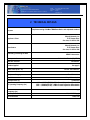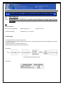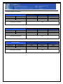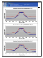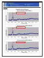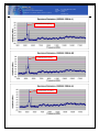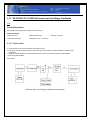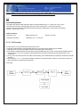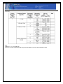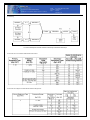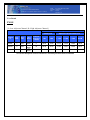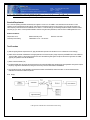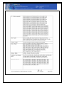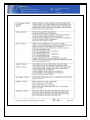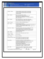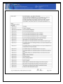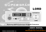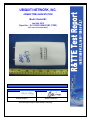
1
UBIQUITI NETWORK, INC.
AIRMAX TDMA BASESTATION
Model: Rocket M3
Jan 26th, 2012
Report No.: SL11102001-UBN-001(RF_PTMP)
(This report supersedes None)
Modifications made to the product : None
This Test Report is Issued Under the Authority of:
David Zhang
Compliance Engineer
Leslie Bai
Director of Certification
This test report may be reproduced in full only.
Title:
To
RF Test Report of AirMax TDMA BaseStation
EN 302 326-2 V1.2.2 (2007-06) ;EN 301 126-2-3 V1.2.1 (2004-11)
Serial#
SL11102001-UBN-001(RF_PTMP)
Issue Date Jan 26th, 2012
Page
2 of 86
www.siemic.com
CERTIFICATE OF TEST
Date of Issue
: Jan 26th, 2012
Company Name
: Ubiquiti Network, Inc.
Product Name/Model : AirMax TDMA BaseStation
/ Rocket M3
Stipulated Standard: (1) EN 302 326-2 V1.2.2 (2007-06)
(2) EN 301 126-2-3 V1.2.1 (2004-11)
Equipment complied with the specification
Equipment did not comply with the specification
[X ]
[ ]
The submission documentation to a National Regulatory Body for type approval
purposes shall consist of two parts; Part one: Application Form;
Part two: Test Report;
Title:
To
RF Test Report of AirMax TDMA BaseStation
EN 302 326-2 V1.2.2 (2007-06) ;EN 301 126-2-3 V1.2.1 (2004-11)
Serial#
SL11102001-UBN-001(RF_PTMP)
Issue Date Jan 26th, 2012
Page
3 of 86
www.siemic.com
ATTESTATION OF CONFORMITY
Presented To:
Ubiquiti Network, Inc.
91 E.Tasman Drive San Jose, CA 95134 USA
For Product/Model:
AirMax TDMA BaseStation
Rocket M3
Was evaluated and confirmed to comply with:
EN 302 326-2 V1.2.2 (2007-06)
EN 301 126-2-3 V1.2.1 (2004-11)
Leslie Bai
Director of Certification
Reference Test Report No.:
SL11102001-UBN-001(RF_PTMP)
Page 1 of 1
Issue Date : Jan 26th, 2012
Test House : SIEMIC Laboratories
Title:
To
RF Test Report of AirMax TDMA BaseStation
EN 302 326-2 V1.2.2 (2007-06) ;EN 301 126-2-3 V1.2.1 (2004-11)
Serial#
SL11102001-UBN-001(RF_PTMP)
Issue Date Jan 26th, 2012
Page
4 of 86
www.siemic.com
Laboratory Introduction
SIEMIC, headquartered in the heart of Silicon Valley, with superior facilities in US and Asia, is one of the leading
independent testing and certification facilities providing customers with one-stop shop services for Compliance Testing and
Global Certifications.
In addition to testing and certification, SIEMIC provides initial design reviews and compliance
management through out a project. Our extensive experience with China, Asia Pacific, North America,
European, and international compliance requirements, assures the fastest, most cost effective way to attain
regulatory compliance for the global markets.
Accreditations for Conformity Assessment
Country/Region
Accreditation Body
Scope
USA
Canada
Taiwan
Hong Kong
Australia
Korea
Japan
Mexico
Europe
FCC, A2LA
IC, A2LA, NIST
BSMI , NCC , NIST
OFTA , NIST
NATA, NIST
KCC/RRA, NIST
VCCI, JATE, TELEC, RFT
NOM, COFETEL, Caniety
A2LA, NIST
EMC , RF/Wireless , Telecom
EMC, RF/Wireless , Telecom
EMC, RF, Telecom , Safety
RF/Wireless ,Telecom
EMC, RF, Telecom , Safety
EMI, EMS, RF , Telecom, Safety
EMI, RF/Wireless, Telecom
Safety, EMC , RF/Wireless, Telecom
EMC, RF, Telecom , Safety
Accreditations for Product Certifications
Country
Accreditation Body
Scope
USA
Canada
Singapore
EU
Japan
HongKong
FCC TCB, NIST
IC FCB , NIST
iDA, NIST
NB
MIC (RCB 208)
OFTA (US002)
EMC , RF , Telecom
EMC , RF , Telecom
EMC , RF , Telecom
EMC & R&TTE Directive
RF , Telecom
RF , Telecom
Title:
To
RF Test Report of AirMax TDMA BaseStation
EN 302 326-2 V1.2.2 (2007-06) ;EN 301 126-2-3 V1.2.1 (2004-11)
This page has been left blank intentionally.
Serial#
SL11102001-UBN-001(RF_PTMP)
Issue Date Jan 26th, 2012
Page
5 of 86
www.siemic.com
Title:
To
RF Test Report of AirMax TDMA BaseStation
EN 302 326-2 V1.2.2 (2007-06) ;EN 301 126-2-3 V1.2.1 (2004-11)
Serial#
SL11102001-UBN-001(RF_PTMP)
Issue Date Jan 26th, 2012
Page
6 of 86
www.siemic.com
CONTENTS
1
EXECUTIVE SUMMARY & EUT INFORMATION ................................................................................................................... 8
2
TECHNICAL DETAILS......................................................................................................................................................... 9
3
MODIFICATION ................................................................................................................................................................ 10
4
TEST SUMMARY .............................................................................................................................................................. 11
5
MEASUREMENTS, EXAMINATION AND DERIVED RESULTS ............................................................................................ 12
ANNEX A. TEST INSTRUMENT & METHOD ............................................................................................................................... 43
ANNEX B EUT PHOTOGRAPHS............................................................................................................................................... 44
ANNEX C. TEST SETUP AND SUPPORTING EQUIPMENT .......................................................................................................... 53
ANNEX D USER MANUAL, BLOCK & CIRCUIT DIAGRAM ......................................................................................................... 58
ANNEX E SIEMIC ACCREDITATION.......................................................................................................................................... 59
Title:
To
RF Test Report of AirMax TDMA BaseStation
EN 302 326-2 V1.2.2 (2007-06) ;EN 301 126-2-3 V1.2.1 (2004-11)
This page has been left blank intentionally.
Serial#
SL11102001-UBN-001(RF_PTMP)
Issue Date Jan 26th, 2012
Page
7 of 86
www.siemic.com
Title:
To
RF Test Report of AirMax TDMA BaseStation
EN 302 326-2 V1.2.2 (2007-06) ;EN 301 126-2-3 V1.2.1 (2004-11)
Serial#
SL11102001-UBN-001(RF_PTMP)
Issue Date Jan 26th, 2012
Page
8 of 86
www.siemic.com
1 Executive Summary & EUT information
The purpose of this test program was to demonstrate compliance of the Ubiquiti Network, Inc., AirMax TDMA
BaseStation, and model: Rocket M3 against the current Stipulated Standards. The Rocket M3 have demonstrated
compliance with the EN 302 326-2 V1.2.2 (2007-06), EN 301 126-2-3 V1.2.1 (2004-11).
EUT Information
EUT
Description
: AirMax TDMA BaseStation
The Rocket is a rugged, hi-power, very linear 2x2 MIMO radio with enhanced receiver
performance. It features incredible range performance (50+km) and breakthrough speed
(150+Mbps real TCPI/IP). The device was specifically designed for outdoor PtP bridging and
PTMP AirMax base-station applications.
Model No
Serial No
Input Power
Classification
Per Stipulated
Test Standard
: Rocket M3
: N/A
:
24V, 1A POE Supply
: Fixed Radio Links
Title:
To
RF Test Report of AirMax TDMA BaseStation
EN 302 326-2 V1.2.2 (2007-06) ;EN 301 126-2-3 V1.2.1 (2004-11)
Serial#
SL11102001-UBN-001(RF_PTMP)
Issue Date Jan 26th, 2012
Page
9 of 86
www.siemic.com
2 TECHNICAL DETAILS
Purpose
Compliance testing of AirMax TDMA BaseStation with stipulated standard
Applicant / Client
Ubiquiti Networks, Inc
91 E.Tasman Drive
San Jose, CA 95134 USA
Manufacturer
Ubiquiti Networks, Inc
91 E.Tasman Drive
San Jose, CA 95134 USA
Laboratory performing the tests
Test report reference number
Date EUT received
Standard applied
Dates of test (from – to)
No of Units:
Equipment Category:
Trade Name:
Microprocessor (s)
RF Operating Frequency (ies)
Clock/Oscillator
Frequency (ies)
Rated Input Power
Port/Connectors
SIEMIC Laboratories
SL11102001-UBN-001(RF_PTMP)
Oct 3rd 2011
See page 2
Oct 3rd - Nov 30th 2011
#1
Fixed Radio Links
Ubiquiti Network, Inc.
unidentified
3,415 – 3,695MHz(TX/RX) / 5MHz Channel Separation & Bandwidth
3,420 – 3,690MHz(TX/RX) / 10MHz Channel Separation & Bandwidth
3,425 – 3,680MHz(TX/RX) / 15MHz Channel Separation & Bandwidth
-24V, 1A POE Supply
RJ45, POE
Title:
To
RF Test Report of AirMax TDMA BaseStation
EN 302 326-2 V1.2.2 (2007-06) ;EN 301 126-2-3 V1.2.1 (2004-11)
Serial#
SL11102001-UBN-001(RF_PTMP)
Issue Date Jan 26th, 2012
Page
10 of 86
www.siemic.com
3 MODIFICATION
NONE
Title:
To
RF Test Report of AirMax TDMA BaseStation
EN 302 326-2 V1.2.2 (2007-06) ;EN 301 126-2-3 V1.2.1 (2004-11)
Serial#
SL11102001-UBN-001(RF_PTMP)
Issue Date Jan 26th, 2012
Page
11 of 86
www.siemic.com
4 TEST SUMMARY
The product was tested in accordance with the following specifications. The Pass / Fail Criteria for the immunity tests were
specified in Annex Ciii.
All Testing has been performed according to below product classification:
Fixed Radio Links
Test Results Summary
Emissions
Test Standard
Description
Transmitter Power
Automatic Transmit Power Control - ATPC
Remote Transmit Power Control – RTPC
Transmitter Output Frequency tolerance
Remote Frequency Control – RFC
Transmitter spectrum density masks
EN 301 126-2-3 V1.2.1 (2004-11)
TX Spurious emissions – external
EN 302 326-2 V1.2.2 (2007-06)
Receiver Input Level Range
RX Spurious emissions
Receiver Input Level Range
FER as a function of RSL
Co-channel “external” and adjacent channel
interference sensitivity
CW spurious interference
PS: All Measurement Uncertainty is not taken into consideration for presented test data
Product Class
See above
See above
See above
See above
See above
See above
See above
See above
See above
See above
See above
Pass / Fail
Pass
N/A
Pass
Pass
Pass
Pass
Pass
N/A
N/A
N/A
Pass
See above
Pass
See above
Pass
Title:
To
RF Test Report of AirMax TDMA BaseStation
EN 302 326-2 V1.2.2 (2007-06) ;EN 301 126-2-3 V1.2.1 (2004-11)
Serial#
SL11102001-UBN-001(RF_PTMP)
Issue Date Jan 26th, 2012
Page
12 of 86
www.siemic.com
5 MEASUREMENTS, EXAMINATION AND DERIVED RESULTS
5.1
TEST RESULT
5.1.1 EN 302 326-2 V1.2.2 (2007-06) Transmitter Power & Remote Transmit Power Control
Test Result
Note:
Ambient conditions:
Temperature: Nominal&Extreme
Relative humidity: 50 %
Tested By: David Zhang
Tested Date: Jan 12 - Jan 26 2012
Pressure: 1019 mbar
Test Procedure
a) Configure the EUT to its maximum out power level.
b) Connect the power measuring head to the RF output port of EUT, read the value and then add the loss calculated above to calculate
the true level of power.
c ) Measure the power of modulated transmission burst
d) Record all measurements and observations in the test file.
Test Setup
Transmitter power measurement test setup
Test Limit:
Title:
To
RF Test Report of AirMax TDMA BaseStation
EN 302 326-2 V1.2.2 (2007-06) ;EN 301 126-2-3 V1.2.1 (2004-11)
Serial#
SL11102001-UBN-001(RF_PTMP)
Issue Date Jan 26th, 2012
Page
13 of 86
www.siemic.com
Test Result (pass/fail criterion)
Test Conditions
Tnom
Vnom(24VDC)
Tmin(-33°C)
Vnom(24VDC)
Tmax(+55°C)
Vnom(24VDC)
Maximum output power observed (dBm)
Remote Transmit Power Control observed
(Yes/No/Not Applicable)
Low Freq
22.78
22.94
22.96
22.96
Transmitter Power (+dBm)
Mid Freq
22.39
22.69
22.71
22.71
High Freq
22.39
22.52
22.49
22.52
Yes
5MHz Channel Separation/Bandwidth Transmitter Power Test Results @ BPSK
Test Conditions
Tnom
Vnom(24VDC)
Tmin(-33°C)
Vnom(24VDC)
Tmax(+55°C)
Vnom(24VDC)
Maximum output power observed (dBm)
Remote Transmit Power Control observed
(Yes/No/Not Applicable)
Low Freq
22.94
23.15
23.13
23.15
Transmitter Power (+dBm)
Mid Freq
22.59
22.88
22.89
22.89
High Freq
22.56
22.77
22.79
22.79
Yes
10MHz Channel Separation/Bandwidth Transmitter Power Test Results @ QPSK
Test Conditions
Tnom
Vnom(24VDC)
Tmin(-33°C)
Vnom(24VDC)
Tmax(+55°C)
Vnom(24VDC)
Maximum output power observed (dBm)
Remote Transmit Power Control observed
(Yes/No/Not Applicable)
Low Freq
22.92
23.25
23.24
23.25
Transmitter Power (+dBm)
Mid Freq
22.77
23.11
23.13
23.13
High Freq
22.57
22.79
22.80
22.80
Yes
15MHz Channel Separation/Bandwidth Transmitter Power Test Results @ 16QAM
Title:
To
RF Test Report of AirMax TDMA BaseStation
EN 302 326-2 V1.2.2 (2007-06) ;EN 301 126-2-3 V1.2.1 (2004-11)
Serial#
SL11102001-UBN-001(RF_PTMP)
Issue Date Jan 26th, 2012
Page
14 of 86
www.siemic.com
5.1.2 EN 302 326-2 V1.2.2 (2007-06) RF Tolerance Test Results
Standard Requirement:
The maximum allowable RF frequency tolerance shall not exceed, by any reason, ±15 ppm, for operation in environmental profile
declared by the supplier.
Ambient conditions:
Temperature: Nominal&Extreme
Relative humidity: 50 %
Tested By: David Zhang
Tested Date: Jan 12 - Jan 26 2012
Pressure: 1019 mbar
Test Procedure
Traditionally, measurements have been performed with a CW signal only but if it is possible to comply with the requirements of the
specification whilst the Tx signal is modulated, then this is preferable since it is easier to set up and may be of interest to regulatory
bodies. Some manufacturer’s equipment may not allow the modulation to be turned off.
a) Set EUT to CW transmitting mode. Connect the spectrum analyser to the RF output port of ODU
b) Tune the spectrum analyser into the nominal Tx frequency.
c) Reduce span and BW until CW is seen.
d) Chose a measurement bandwidth, for example 10kHz.
e) Put the marker of the spectrum analyser on the CW signal from the EUT.
f) Select the Frequency Count option on the spectrum analyser if available, otherwise read the marker frequency.
Test Setup
RFC measurement test setup
Title:
To
RF Test Report of AirMax TDMA BaseStation
EN 302 326-2 V1.2.2 (2007-06) ;EN 301 126-2-3 V1.2.1 (2004-11)
Serial#
SL11102001-UBN-001(RF_PTMP)
Issue Date Jan 26th, 2012
Page
15 of 86
www.siemic.com
Test Result ( pass/fail criterion)
Test Conditions
Tnom
Vnom(24VDC)
Tmin(-33°C)
Vnom(24VDC)
Tmax(+55°C)
Vnom(24VDC)
Maximum Frequency Deviation observed
(PPM)
Remote Transmit Frequency Control
observed (Yes/No/Not Applicable)
Low Freq
3415.0080
3415.0120
3415.0120
Transmitter Frequency (MHz)
Mid Freq
3555.0150
3555.0120
3555.0110
High Freq
3695.0150
3695.0100
3695.0120
3.51
4.22
4.06
Yes
5MHz Channel Separation/Bandwidth Transmitter Frequency Test Results @ BPSK
Test Conditions
Tnom
Vnom(24VDC)
Tmin(-33°C)
Vnom(24VDC)
Tmax(+55°C)
Vnom(24VDC)
Maximum Frequency Deviation observed
(PPM)
Remote Transmit Frequency Control
observed (Yes/No/Not Applicable)
Low Freq
3420.0050
3420.0130
3420.0120
Transmitter Frequency (MHz)
Mid Freq
3550.0170
3550.0120
3550.0120
High Freq
3690.0150
3690.0120
3690.0110
3.80
4.79
4.07
Yes
10MHz Channel Separation/Bandwidth Transmitter Frequency Test Results @ QPSK
Test Conditions
Tnom
Vnom(24VDC)
Tmin(-33°C)
Vnom(24VDC)
Tmax(+55°C)
Vnom(24VDC)
Maximum Frequency Deviation observed
(PPM)
Remote Transmit Frequency Control
observed (Yes/No/Not Applicable)
Low Freq
3425.0170
3425.0120
3425.0120
Transmitter Frequency (MHz)
Mid Freq
3545.0170
3545.0120
3545.0120
High Freq
3680.0150
3680.0070
3680.0070
4.96
4.80
4.08
Yes
15MHz Channel Separation/Bandwidth Transmitter Frequency Test Results @ 16QAM
Title:
To
Serial#
SL11102001-UBN-001(RF_PTMP)
Issue Date Jan 26th, 2012
Page
16 of 86
www.siemic.com
RF Test Report of AirMax TDMA BaseStation
EN 302 326-2 V1.2.2 (2007-06) ;EN 301 126-2-3 V1.2.1 (2004-11)
5.1.3 EN 302 326-2 V1.2.2 (2007-06) Radio Frequency (RF) spectrum masks Test Results
Standard Requirement:
The 0 dB level shown on the spectrum masks relates to the spectral power density at the carrier centre frequency,disregarding the
residual of the carrier (due to modulation imperfection). The actual carrier frequency is identified with the f0 corner point; spectrum masks
are shown in frequencies relative to f0; the spectrum mask is assumed to be symmetrical with respect to the centre frequency f0.
Radio frequency spectrum mask limits have been reduced to a set of curves and a set of discreet points (i.e. fx MHz/Kx dB) identifying
the frequency offset from f0 and the related attenuation; each curve is divided into a number of segments; each spectrum mask is then
represented by values located at discrete points on the relevant graph; the number of discreet points is dependent on the number of
segments on the actual mask.
It is also assumed that the value associated with the final discreet point on the graph extends to a point equal to
2,5 times the channel separation (i.e. 2,5 × CS) on each side of the centre frequency.
Ambient conditions:
Temperature: Nominal&Extreme
Relative humidity: 95 %
Pressure: 1019 mbar
Tested By: David Zhang
Tested Date: Jan 12 - Jan 26 2012
Test Procedure
The test examines the R.F. Spectrum of the output signal. It is possible to see any spurious emissions which may be emitted by the EUT.
Measurements are done relative to the output frequency of the EUT. Compliance with the requirements is shown, when the
emitted spectrum falls below a specified limit line.
A sample spectrum mask is shown on figure below,
6
5
MASK
3
4
7
8
CENTRE
FREQUECY
1
2
9
10
EUT OUTPUT
SPECTRUM
The transmitter output port shall be connected to either a Spectrum Analyser via an attenuator or an artificial load with some means of
monitoring the emissions with a Spectrum Analyser. The Spectrum Analyser shall have a variable persistence display or a digital storage
facility. When not stated in the relevant EN/ETS, the resolution bandwidth, frequency span, scan time and video filter settings of the
Spectrum Analyser are to be set in accordance with the following indications. A power splitter or coupler may be required if the TS
requires an RF link from the CRS before it can operate.
With the transmitter modulated by a signal having the characteristics given in the relevant EN/ETS, the transmitter power density,
(including the spectral lines at the symbol rate if stated in the EN/ETS), shall be measured by the Spectrum Analyser and recorded.
Where possible, transmitter spectral power density plots at the lowest, mid-band and highest frequencies of the supplier's declared
operating range are to be recorded.
The spectrum of a single carrier has to be verified at both edges of the spectrum mask for the RF channel of the relevant product
standard.
Title:
To
RF Test Report of AirMax TDMA BaseStation
EN 302 326-2 V1.2.2 (2007-06) ;EN 301 126-2-3 V1.2.1 (2004-11)
Serial#
SL11102001-UBN-001(RF_PTMP)
Issue Date Jan 26th, 2012
Page
17 of 86
www.siemic.com
Test Setup
RF Spectrum Mask measurement test setup
Test Limit:
Title:
To
RF Test Report of AirMax TDMA BaseStation
EN 302 326-2 V1.2.2 (2007-06) ;EN 301 126-2-3 V1.2.1 (2004-11)
Serial#
SL11102001-UBN-001(RF_PTMP)
Issue Date Jan 26th, 2012
Page
18 of 86
www.siemic.com
Test Result:
SPECTRUM MASK ( BPSK MODE)
Channel
Separation
Frequency
Temperature
Voltage
Pass/Fail
Nominal
Nominal
Pass
Low
Nominal
Pass
High
Nominal
Pass
Nominal
Nominal
Pass
Mid
Low
Nominal
Pass
High
Nominal
Pass
Nominal
Nominal
Pass
High
Low
Nominal
Pass
High
Nominal
Pass
Spectrum Mask – 5MHz Channel Separation/Bandwidth @ BPSK
Low
5MHz
SPECTRUM MASK ( QPSK MODE)
Channel
Separation
Frequency
Temperature
Voltage
Pass/Fail
Nominal
Nominal
Pass
Low
Nominal
Pass
High
Nominal
Pass
Nominal
Nominal
Pass
Mid
Low
Nominal
Pass
High
Nominal
Pass
Nominal
Nominal
Pass
High
Low
Nominal
Pass
High
Nominal
Pass
Spectrum Mask – 10MHz Channel Separation/Bandwidth @ QPSK
Low
10MHz
SPECTRUM MASK ( 16QAM MODE)
Channel
Separation
Frequency
Voltage
Pass/Fail
Nominal
Nominal
Pass
Low
Nominal
Pass
High
Nominal
Pass
Nominal
Nominal
Pass
Mid
Low
Nominal
Pass
High
Nominal
Pass
Nominal
Nominal
Pass
High
Low
Nominal
Pass
High
Nominal
Pass
Spectrum Mask – 15MHz Channel Separation/Bandwidth @ 16QAM
Low
15MHz
Temperature
Title:
To
RF Test Report of AirMax TDMA BaseStation
EN 302 326-2 V1.2.2 (2007-06) ;EN 301 126-2-3 V1.2.1 (2004-11)
Serial#
SL11102001-UBN-001(RF_PTMP)
Issue Date Jan 26th, 2012
Page
19 of 86
www.siemic.com
Title:
To
RF Test Report of AirMax TDMA BaseStation
EN 302 326-2 V1.2.2 (2007-06) ;EN 301 126-2-3 V1.2.1 (2004-11)
Serial#
SL11102001-UBN-001(RF_PTMP)
Issue Date Jan 26th, 2012
Page
20 of 86
www.siemic.com
Title:
To
RF Test Report of AirMax TDMA BaseStation
EN 302 326-2 V1.2.2 (2007-06) ;EN 301 126-2-3 V1.2.1 (2004-11)
Serial#
SL11102001-UBN-001(RF_PTMP)
Issue Date Jan 26th, 2012
Page
21 of 86
www.siemic.com
Title:
To
RF Test Report of AirMax TDMA BaseStation
EN 302 326-2 V1.2.2 (2007-06) ;EN 301 126-2-3 V1.2.1 (2004-11)
Serial#
SL11102001-UBN-001(RF_PTMP)
Issue Date Jan 26th, 2012
Page
22 of 86
www.siemic.com
Title:
To
RF Test Report of AirMax TDMA BaseStation
EN 302 326-2 V1.2.2 (2007-06) ;EN 301 126-2-3 V1.2.1 (2004-11)
Serial#
SL11102001-UBN-001(RF_PTMP)
Issue Date Jan 26th, 2012
Page
23 of 86
www.siemic.com
Title:
To
RF Test Report of AirMax TDMA BaseStation
EN 302 326-2 V1.2.2 (2007-06) ;EN 301 126-2-3 V1.2.1 (2004-11)
Serial#
SL11102001-UBN-001(RF_PTMP)
Issue Date Jan 26th, 2012
Page
24 of 86
www.siemic.com
Title:
To
RF Test Report of AirMax TDMA BaseStation
EN 302 326-2 V1.2.2 (2007-06) ;EN 301 126-2-3 V1.2.1 (2004-11)
Serial#
SL11102001-UBN-001(RF_PTMP)
Issue Date Jan 26th, 2012
Page
25 of 86
www.siemic.com
Title:
To
RF Test Report of AirMax TDMA BaseStation
EN 302 326-2 V1.2.2 (2007-06) ;EN 301 126-2-3 V1.2.1 (2004-11)
Serial#
SL11102001-UBN-001(RF_PTMP)
Issue Date Jan 26th, 2012
Page
26 of 86
www.siemic.com
Title:
To
RF Test Report of AirMax TDMA BaseStation
EN 302 326-2 V1.2.2 (2007-06) ;EN 301 126-2-3 V1.2.1 (2004-11)
Serial#
SL11102001-UBN-001(RF_PTMP)
Issue Date Jan 26th, 2012
Page
27 of 86
www.siemic.com
Title:
To
RF Test Report of AirMax TDMA BaseStation
EN 302 326-2 V1.2.2 (2007-06) ;EN 301 126-2-3 V1.2.1 (2004-11)
Serial#
SL11102001-UBN-001(RF_PTMP)
Issue Date Jan 26th, 2012
Page
28 of 86
www.siemic.com
5.1.4 EN 302 326-2 V1.2.2 (2007-06) spurious Emissions (External) Test Results
Standard Requirement:
For Fixed Service systems, spurious emissions are defined by CEPT/ERC/REC 74-01 [1] as those emissions at frequencies that are
removed from the nominal carrier frequency by more than 250 % of the relevant channel separation.
It is necessary to define spurious emissions (or more precisely, according latest ITU-R definitions, unwanted emissions in the spurious
domain) from transmitters in order to limit interference into other systems operating wholly externally to the system under consideration
(external emissions). Limits are set out by EN 301 390.
Spurious Emissions Limit
SPURIOUS DOMAIN EMISSION LIMIT
Type of Equipment
BWA systems operating between 1 GHz and 6 GHz (all
transmitting stations)
Mean power or , when applicable, average power during
bursts duration in the reference bandwidth
-36 dBm, for 9 kHz < f < 1 GHz
-30 dBm , for 1 GHz < f < FUPPER
Measurement Frequency Range
Fundamental frequency
range
9 kHz - 100 MHz
100 MHz - 300 MHz
300 MHz - 600 MHz
600 MHz - 5.2 GHz
5.2 GHz - 13 GHz
13 GHz - 150 GHz
150 GHz - 300 GHz
Lower frequency
9 kHz
9 kHz
30 MHz
30 MHz
30 MHz
30 MHz
30 MHz
Frequency range for measurements
Upper frequency
(The test should include the entire harmonic band and
not be truncated at the precise upper frequency limit
stated)
1 GHz
10th harmonic
3 GHz
5th harmonic
26 GHz
2nd harmonic
300 GHz
Ambient conditions:
Temperature: 25.2°C
Relative humidity: 50 %
Tested By: David Zhang
Tested Date: Jan 12 - Jan 26 2012
Pressure: 1019 mbar
5.1.4.1 Test Procedure
The transmitter output port shall be connected to either a Spectrum Analyzer via a suitable attenuator and/or notch filter to limit the
power into the front end of the Analyzer. In some cases, where the upper frequency limit exceeds the basic operating range of the
Analyzer, suitable waveguide transitions and mixer will be required. It is important that the circuit between the transmitter and the input
to the mixer, or Spectrum Analyzer, is characterized over the frequency range to be measured. These losses should be used to set the
limit line of the Analyzer to a value which ensures that the specification criteria at point C' is not exceeded.
The transmitter is to be operated at the supplier's maximum rated output power and the level and frequency of all significant signals are to
be measured and plotted throughout the frequency band quoted in the relevant specification. It is recommended that each scan be taken
in 5 GHz steps below 21,2 GHz and 10 GHz steps above 21,2 GHz. However, spurious emissions close to the limit should be plotted over
a restricted range which clearly demonstrates that the signal does not exceed the relevant limit.The measurement for the TS is performed
with one single carrier only.
Title:
To
RF Test Report of AirMax TDMA BaseStation
EN 302 326-2 V1.2.2 (2007-06) ;EN 301 126-2-3 V1.2.1 (2004-11)
Serial#
SL11102001-UBN-001(RF_PTMP)
Issue Date Jan 26th, 2012
Page
29 of 86
www.siemic.com
Test Setup
Spurious Emissions (External) measurement test setup
Test Result
PASS
Title:
To
Test Plots
RF Test Report of AirMax TDMA BaseStation
EN 302 326-2 V1.2.2 (2007-06) ;EN 301 126-2-3 V1.2.1 (2004-11)
Serial#
SL11102001-UBN-001(RF_PTMP)
Issue Date Jan 26th, 2012
Page
30 of 86
www.siemic.com
Transmitter Spurious Emission
Fundamental Frequency
Fundamental Frequency
Fundamental Frequency
Title:
To
RF Test Report of AirMax TDMA BaseStation
EN 302 326-2 V1.2.2 (2007-06) ;EN 301 126-2-3 V1.2.1 (2004-11)
Fundamental Frequency
Fundamental Frequency
Fundamental Frequency
Serial#
SL11102001-UBN-001(RF_PTMP)
Issue Date Jan 26th, 2012
Page
31 of 86
www.siemic.com
Title:
To
RF Test Report of AirMax TDMA BaseStation
EN 302 326-2 V1.2.2 (2007-06) ;EN 301 126-2-3 V1.2.1 (2004-11)
Fundamental Frequency
Fundamental Frequency
Fundamental Frequency
Serial#
SL11102001-UBN-001(RF_PTMP)
Issue Date Jan 26th, 2012
Page
32 of 86
www.siemic.com
Title:
To
RF Test Report of AirMax TDMA BaseStation
EN 302 326-2 V1.2.2 (2007-06) ;EN 301 126-2-3 V1.2.1 (2004-11)
Serial#
SL11102001-UBN-001(RF_PTMP)
Issue Date Jan 26th, 2012
Page
33 of 86
www.siemic.com
5.1.5 EN 302 326-2 V1.2.2 (2007-06) Receiver Input Level Range Test Results
Note:
Standard Requirement:
Minimum RSL under single signal conditions shall be measured.
Ambient conditions:
Temperature: 25°C
Relative humidity: 50 %
Tested By: David Zhang
Tested Date: Jan 12 - Jan 26 2012
Pressure: 1019 mbar
5.1.5.1 Test Procedure
a) Power the EUT on and ensure that data is passing with no errors.
b) The input level to the Rx shall be set to the upper and lower levels specified in the relevant ETS/EN or declared by the
manufacturer
c) Adjust the variable attenuators such that the RSL at the EUT is set to the minimum stated level for the first BER.
c) Record the measured BER.
Test setup
Receiver Input Level Range measurement test setup
Title:
To
RF Test Report of AirMax TDMA BaseStation
EN 302 326-2 V1.2.2 (2007-06) ;EN 301 126-2-3 V1.2.1 (2004-11)
Serial#
SL11102001-UBN-001(RF_PTMP)
Issue Date Jan 26th, 2012
Page
34 of 86
www.siemic.com
Test Result
PASS
Middle Channel
Modulation
Channel
Separation (MHz)
Center Frequency
(MHz)
Upper
Receiver
Input Level
(dBm)
Lower
Receiver
Input Level
(dBm)
Receiver Input
Range (dB)
BPSK
QPSK
5
10
3555
3550
23.0
23.2
-94.6
-93.2
117.6
116.4
16QAM
15
Low Channel
5
10
15
High Channel
5
10
15
3545
23.3
-90.4
113.7
3555
3550
3545
23.1
23.2
23.2
-94.2
-92.8
-90.7
117.3
116.0
113.9
3555
3550
3545
22.9
23.2
23.2
-94.5
-93.1
-90.3
117.4
116.3
113.5
BPSK
QPSK
16QAM
BPSK
QPSK
16QAM
Receiver Input Level Range Test Results
Title:
To
RF Test Report of AirMax TDMA BaseStation
EN 302 326-2 V1.2.2 (2007-06) ;EN 301 126-2-3 V1.2.1 (2004-11)
Serial#
SL11102001-UBN-001(RF_PTMP)
Issue Date Jan 26th, 2012
Page
35 of 86
www.siemic.com
5.1.6 BER as a function of receiver input signal level Test Results
Note:
Standard Requirement:
The supplier shall declare the RSL threshold(s) (dBm) for the relevant BER values (i.e. 10-6 and 10-8 or 10-10), which
shall not be worse than the corresponding RSL upper bound values indicated in the `s of the relevant annex(es).
Equipment working at the relevant declared RSL thresholds shall produce a BER equal to or less than the corresponding
values (i.e. 10-6 and 10-8 or 10-10).
Ambient conditions:
Temperature: 25°C
Relative humidity: 50 %
Tested By: David Zhang
Tested Date: Jan 12 - Jan 26 2012
Pressure: 1019 mbar
5.1.6.1 Test Procedure
a) Power the EUT on and ensure that data is passing with no errors.
b) Adjust the variable attenuators such that the RSL at the EUT is set to the minimum stated level for the first BER.
c) With the RSL set, observe the EUT BER for at least the calculated test time. Note the result.
d) Now adjust the variable attenuators whilst constantly monitoring the BER tester until you reach an RSL whereby the BER does equal
the level specified. This is not a requirement of the specification but actual receiver thresholds are important information for the
manufacturer.
e) Once you have achieved the pass/fail level of BER, note the settings on the variable attenuators and therefore calculate the actual RSL
at the EUT.
f) Now repeat steps ‘b’ to ‘e’ for the next level of BER as specified, using the relevant RSL for that test. These levels are found in the
generic specification or specified by the manufacturer.
Test setup
Title:
To
RF Test Report of AirMax TDMA BaseStation
EN 302 326-2 V1.2.2 (2007-06) ;EN 301 126-2-3 V1.2.1 (2004-11)
Serial#
SL11102001-UBN-001(RF_PTMP)
Issue Date Jan 26th, 2012
Page
36 of 86
www.siemic.com
Test Limit:
Note:
TBER(A, B) = (A + 10 log10(B)) dBm
where A is a constant and B is either GBR, the gross bit rate in Mbit/s or ChS, the channel separation in MHz.
Title:
To
RF Test Report of AirMax TDMA BaseStation
EN 302 326-2 V1.2.2 (2007-06) ;EN 301 126-2-3 V1.2.1 (2004-11)
Serial#
SL11102001-UBN-001(RF_PTMP)
Issue Date Jan 26th, 2012
Page
37 of 86
www.siemic.com
Test Result
PASS
Middle Channel
Nominal
EqC-SET
bit rate
(Mbit/s)
Channel
Separation
(MHz)
Center
Frequency
(MHz)
25°C
RSL for
BER≤10^-6
(dBm)
-33°C
RSL for
BER≤10^-6
(dBm)
55°C
RSL for
BER≤10^-6
(dBm)
-90.1
-88.4
-90.3
-89.1
Modulation
EqCEMO
BPSK
QPSK
1
2
NULL
NULL
≥2 Mbits
≥2 Mbits
5
10
3555
3550
-90.2
-89.1
16QAM
4
NULL
≥4 Mbits
Low Channel
NULL
≥2 Mbits
NULL
≥2 Mbits
NULL
≥4 Mbits
High Channel
NULL
≥2 Mbits
NULL
≥2 Mbits
NULL
≥4 Mbits
15
3545
-85.7
25°C
-91.8
-88.7
-86.6
25°C
-90.1
-88.1
-86.2
BPSK
QPSK
16QAM
BPSK
QPSK
16QAM
1
2
4
1
2
4
5
10
15
5
10
15
3555
3550
3545
3555
3550
3545
RSL Test Results
-86.3
-86.1
-33°C
55°C
-92.3
-89.2
-86.8
-91.9
-88.9
-86.6
-33°C
55°C
-90.6
-89.4
-86.8
-90.3
-88.5
-86.0
Title:
To
RF Test Report of AirMax TDMA BaseStation
EN 302 326-2 V1.2.2 (2007-06) ;EN 301 126-2-3 V1.2.1 (2004-11)
Serial#
SL11102001-UBN-001(RF_PTMP)
Issue Date Jan 26th, 2012
Page
38 of 86
www.siemic.com
5.1.7 EN 302 326-2 V1.2.2 (2007-06) Co-channel “external” and adjacent channel
interference sensitivity Test Results
Standard Requirement:
The limits of Carrier to Interference ratio (C/I) in case of co-channel and adjacent channel interference shall be as specified in the relevant
tables of annexes A to E in standard of EN302 217-2-2, giving maximum C/I values for 1 dB and 3 dB degradation of the RSL limits
declared by the supplier for a BER ≤ 10-6 in clause 4.3.2 in standard of EN302 217-2-2.
Ambient conditions:
Temperature: 25°C
Relative humidity: 50 %
Tested By: David Zhang
Tested Date: Jan 12 - Jan 26 2012
Pressure: 1019 mbar
5.1.7.1 Test Procedure
a) Set attenuators at both paths to maximum.
b) With the interfering path attenuators set to maximum, adjust the intended path attenuators such that the RSL at the EUT is as stated in
the specification.
c) Check with the BER tester that a link is being made and that the EUT is able to comply with the BER requirements of the test with no
interfering signal present.
d) Set the interfering radio to one channel lower than the EUT.
e) Reduce the level of attenuation in the interfering path from the third radio until the interfering signal at the output of attenuator A2 is as
stated in the specification. This will need to be calculated from the calibration performed above.
f) With the RSL and interfering level set, observe the EUT BER for at least the calculated test time. Note the result.
g) Now reduce the attenuation in the interfering path whilst constantly monitoring the BER tester until you reach an interfering signal level
whereby the BER does equal the level specified. This is not a requirement of the specification but actual C/I thresholds are important
information for the manufacturer.
h) Once you have achieved the pass/fail level of BER, note the settings on the variable attenuators and therefore calculate the actual C/I
at the EUT.
i) Now repeat steps c) to i) for the next levels of BER and limit degradation as specified, using the relevant C/I for that test. These
levels are dictated by the specification or manufacturer.
j) Determine BER compliance and then an actual RSL threshold for each level of BER.
k) The above procedure must be followed with the interfering radio set to one channel lower and one channel higher than the EUT,
therefore set the interfering support radio to one channel higher than the EUT and repeat steps f) to k).
Title:
To
RF Test Report of AirMax TDMA BaseStation
EN 302 326-2 V1.2.2 (2007-06) ;EN 301 126-2-3 V1.2.1 (2004-11)
Serial#
SL11102001-UBN-001(RF_PTMP)
Issue Date Jan 26th, 2012
Page
39 of 86
www.siemic.com
Test Setup
Co-channel and adjacent channel interference sensitivity measurement test setups
Test Limit for Co-Channel Interference Rejection:
Test Limit for Adjacent-Channel Interference Rejection:
Title:
To
RF Test Report of AirMax TDMA BaseStation
EN 302 326-2 V1.2.2 (2007-06) ;EN 301 126-2-3 V1.2.1 (2004-11)
Serial#
SL11102001-UBN-001(RF_PTMP)
Issue Date Jan 26th, 2012
Page
40 of 86
www.siemic.com
Test Result
PASS
[L=Low Adjacent Channel, H= High Adjacent Channel]
C/I for BER ≤ 10^-6 RSL degradation of 1 dB or 3 dB
Co-channel
Adjacent Channel Interference
Interference
Modulati
on
EqCEMO
EqCSET
BPSK
1
NULL
QPSK
2
NULL
16QAM
4
NULL
Bit
rate (
Mbit/s
)
≥2
Mbits
≥2
Mbits
≥4
Mbits
Channel
Separatio
n (MHz)
1dB
3dB
L 1dB
H 1dB
L 3dB
H 3dB
5
22.50
19.62
-13.73
-14.45
-15.89
-16.24
10
25.02
20.93
-12.89
-13.21
-15.05
-15.21
15
26.13
22.31
-13.62
-14.15
-15.58
-15.98
Co-channel & adjacent channel interference sensitivity measurement Test Results
Title:
To
RF Test Report of AirMax TDMA BaseStation
EN 302 326-2 V1.2.2 (2007-06) ;EN 301 126-2-3 V1.2.1 (2004-11)
Serial#
SL11102001-UBN-001(RF_PTMP)
Issue Date Jan 26th, 2012
Page
41 of 86
www.siemic.com
5.1.8 EN 302 326-2 V1.2.2 (2007-06) CW spurious interference Test Results
Standard Requirement:
For a receiver operating at the RSL declared by the supplier in clause 4.3.2 for a BER ≤ 10-6 threshold, the introduction of a CW
interferer at a level specified by EN 301 390 [5], with respect to the wanted signal and at any frequency up to the relevant upper and
lower frequency limits derived from the table set out in clause 7.1 of EN 301 390 [5], but excluding frequencies either side of the wanted
frequency by up to 250 % of the separation between channels using the same polarization, shall not result in a BER greater than 10-5.
Ambient conditions:
Temperature: 25°C
Relative humidity: 50 %
Tested By: David Zhang
Tested Date: Jan 12 - Jan 26 2012
Pressure: 1019 mbar
Test Procedure
a) With the signal generator output turned off, apply the calibration procedure of subclause 4.4.4.3 in EN301126-2-3 accordingly.
b) Switch off the transmitter. Calibrate the CW-signal generator across the frequency range required by the EN/ETS at a level x dB above
the level (dBm), where x is the required increase in level for the interfering CW signal in respect to the receive signal level for a BER
(typically 10-6) stated in the relevant EN/ETS.
c) Switch on the transmitter (Tx1).
d) Confirm the BER does not exceed the value specified in the relevant ETS/EN when sweeping the signal generator through the required
frequency range at the calibrated level, taking into account any exclusion band stated in the EN/ETS.
e) Any frequencies, which cause the BER to exceed the level stated in the EN/ETS, shall be recorded. It is recommended that the
calibration be rechecked at these frequencies.
Test Setup
CW spurious interference measurement test setup
Title:
To
RF Test Report of AirMax TDMA BaseStation
EN 302 326-2 V1.2.2 (2007-06) ;EN 301 126-2-3 V1.2.1 (2004-11)
Serial#
SL11102001-UBN-001(RF_PTMP)
Issue Date Jan 26th, 2012
Page
42 of 86
www.siemic.com
Test Result
PASS
[CW Interference (dB) means the that level relative to manufacturer declared RSL for BER≤10^-6]
CW Interference (dB)
30
30
30
30
30
30
F low (MHz)
Channel Spacing = 5MHz
30.0
3582.5
Channel Spacing = 10MHz
30.0
3605.0
Channel Spacing = 15MHz
30.0
3627.5
CW spurious interference measurement Test Results
No degradation of BER>10^-5, for all frequency ranges.
F high ( MHz)
3527.5
17775.0
3495.0
17750.0
3462.5
17725.0
Title:
To
RF Test Report of AirMax TDMA BaseStation
EN 302 326-2 V1.2.2 (2007-06) ;EN 301 126-2-3 V1.2.1 (2004-11)
Serial#
SL11102001-UBN-001(RF_PTMP)
Issue Date Jan 26th, 2012
Page
43 of 86
www.siemic.com
Annex A. TEST INSTRUMENT & METHOD
Annex A.i. TEST INSTRUMENTATION & GENERAL PROCEDURES
Instrument
Model
Serial #
Calibration Due
ESIB 40
1007H
100179
61201
04/25/2012
05/17/2012
437B
8564E
3038A03648
3738A00962
05/17/2012
05/17/2012
437B
8564E
3038A03648
3738A00962
05/17/2012
05/17/2012
437B
8564E
3038A03648
3738A00962
05/17/2012
05/17/2012
437B
8564E
3784A
ASA-PKG-OC3
3038A03648
3738A00962
3784A
ASA-PKG-OC3
05/17/2012
05/17/2012
05/17/2012
05/17/2012
8564E
Flann 20110
3738A00962
974
05/17/2012
Functional verification
437B
8564E
3784A
ASA-PKG-OC3
3038A03648
3738A00962
3784A
ASA-PKG-OC3
05/17/2012
05/17/2012
05/17/2012
05/17/2012
437B
8564E
3784A
ASA-PKG-OC3
3038A03648
3738A00962
3784A
ASA-PKG-OC3
05/17/2012
05/17/2012
05/17/2012
05/17/2012
437B
8564E
3784A
ASA-PKG-OC3
68169B
3038A03648
3738A00962
3784A
ASA-PKG-OC3
973407
05/17/2012
05/17/2012
05/17/2012
05/17/2012
05/17/2012
Permitted Freq Range
R&S EMI Receiver
TestEquity Environment Chamber
Transmitter Power
HP Power Meter
Spectrum Analyzer (9 kHz-40GHz)
Adjacent channel power – RTPC
HP Power Meter
Spectrum Analyzer (9 kHz-40GHz)
Transmitter power tolerance
HP Power Meter
Spectrum Analyzer (9 kHz-40GHz)
Radio Frequency (RF) spectrum masks
HP Power Meter
Spectrum Analyzer (9 kHz-40GHz)
HP Digital Transmissions Analyzer
Digital LightWave Transmissions Analyzer
TX Spurious emissions – external
Spectrum Analyzer (9 kHz-40GHz)
Precision Variable Attenuator
BER as a function of RSL
HP Power Meter
Spectrum Analyzer (9 kHz-40GHz)
HP Digital Transmissions Analyzer
Digital LightWave Transmissions Analyzer
Co-channel & Adjacent channel
interference sensitivity
HP Power Meter
Spectrum Analyzer (9 kHz-40GHz)
HP Digital Transmissions Analyzer
Digital LightWave Transmissions Analyzer
CW spurious interference
HP Power Meter
Spectrum Analyzer (9 kHz-40GHz)
HP Digital Transmissions Analyzer
Digital LightWave Transmissions Analyzer
Wiltron Synthesized Sweep Generator
Title:
To
RF Test Report of AirMax TDMA BaseStation
EN 302 326-2 V1.2.2 (2007-06) ;EN 301 126-2-3 V1.2.1 (2004-11)
Serial#
SL11102001-UBN-001(RF_PTMP)
Issue Date Jan 26th, 2012
Page
44 of 86
www.siemic.com
Annex B EUT PHOTOGRAPHS
Annex B.i.
Photograph 1: EUT External Photo
EUT - Front View
EUT – Rear View
Title:
To
RF Test Report of AirMax TDMA BaseStation
EN 302 326-2 V1.2.2 (2007-06) ;EN 301 126-2-3 V1.2.1 (2004-11)
Serial#
SL11102001-UBN-001(RF_PTMP)
Issue Date Jan 26th, 2012
Page
45 of 86
www.siemic.com
EUT - Top View
EUT - Bottom View
Title:
To
RF Test Report of AirMax TDMA BaseStation
EN 302 326-2 V1.2.2 (2007-06) ;EN 301 126-2-3 V1.2.1 (2004-11)
EUT - Right View
EUT - Left View
Serial#
SL11102001-UBN-001(RF_PTMP)
Issue Date Jan 26th, 2012
Page
46 of 86
www.siemic.com
Title:
To
RF Test Report of AirMax TDMA BaseStation
EN 302 326-2 V1.2.2 (2007-06) ;EN 301 126-2-3 V1.2.1 (2004-11)
Serial#
SL11102001-UBN-001(RF_PTMP)
Issue Date Jan 26th, 2012
Page
47 of 86
www.siemic.com
PoE Adapter – Top View
PoE Adapter - Bottom View
Title:
To
RF Test Report of AirMax TDMA BaseStation
EN 302 326-2 V1.2.2 (2007-06) ;EN 301 126-2-3 V1.2.1 (2004-11)
Serial#
SL11102001-UBN-001(RF_PTMP)
Issue Date Jan 26th, 2012
Page
48 of 86
www.siemic.com
PoE Adapter – Front View
PoE Adapter - Rear View
Title:
To
RF Test Report of AirMax TDMA BaseStation
EN 302 326-2 V1.2.2 (2007-06) ;EN 301 126-2-3 V1.2.1 (2004-11)
Serial#
SL11102001-UBN-001(RF_PTMP)
Issue Date Jan 26th, 2012
Page
49 of 86
www.siemic.com
Dish Antenna - Front View
Dish Antenna - Back View
Title:
To
RF Test Report of AirMax TDMA BaseStation
EN 302 326-2 V1.2.2 (2007-06) ;EN 301 126-2-3 V1.2.1 (2004-11)
Serial#
SL11102001-UBN-001(RF_PTMP)
Issue Date Jan 26th, 2012
Page
50 of 86
www.siemic.com
Sector Antenna - Top View
Sector Antenna - Bottom View
Title:
To
Annex B.ii.
RF Test Report of AirMax TDMA BaseStation
EN 302 326-2 V1.2.2 (2007-06) ;EN 301 126-2-3 V1.2.1 (2004-11)
Photograph 2: EUT Internal Photo
N/A
Serial#
SL11102001-UBN-001(RF_PTMP)
Issue Date Jan 26th, 2012
Page
51 of 86
www.siemic.com
Title:
To
Annex B.iii.
RF Test Report of AirMax TDMA BaseStation
EN 302 326-2 V1.2.2 (2007-06) ;EN 301 126-2-3 V1.2.1 (2004-11)
Photograph 3: Test Setup Photo
N/A
Serial#
SL11102001-UBN-001(RF_PTMP)
Issue Date Jan 26th, 2012
Page
52 of 86
www.siemic.com
Title:
To
RF Test Report of AirMax TDMA BaseStation
EN 302 326-2 V1.2.2 (2007-06) ;EN 301 126-2-3 V1.2.1 (2004-11)
Serial#
SL11102001-UBN-001(RF_PTMP)
Issue Date Jan 26th, 2012
Page
53 of 86
www.siemic.com
Annex C. TEST SETUP AND SUPPORTING EQUIPMENT
TEST CONDITIONS
Annex C. i.
SUPPORTING EQUIPMENT DESCRIPTION
The following is a description of supporting equipment and details of cables used with the EUT.
Equipment Description
(Including Brand Name)
Model & Serial Number
Cable Description
(List Length, Type & Purpose)
1* PC Laptop / DELL
Latitude D600
Shielded RJ45 Cable , 2 meter ( From PC to EUT)
AirMax TDMA Base station
Rocket M3
Shielded RJ45 Cable , 2 meter
2* PoE
N/A
Shielded RJ45 Cable , 2 meter
Variable Attenuator
Agilent/H281A
RF Cable, 30cm
Coupler
CMT/971722-072
Waveguide
Title:
To
RF Test Report of AirMax TDMA BaseStation
EN 302 326-2 V1.2.2 (2007-06) ;EN 301 126-2-3 V1.2.1 (2004-11)
Block Configuration Diagram for Radiated Emission
N/A
Serial#
SL11102001-UBN-001(RF_PTMP)
Issue Date Jan 26th, 2012
Page
54 of 86
www.siemic.com
Title:
To
RF Test Report of AirMax TDMA BaseStation
EN 302 326-2 V1.2.2 (2007-06) ;EN 301 126-2-3 V1.2.1 (2004-11)
Block Configuration Diagram for Conducted Emission
N/A
Serial#
SL11102001-UBN-001(RF_PTMP)
Issue Date Jan 26th, 2012
Page
55 of 86
www.siemic.com
Title:
To
Annex C.ii.
Serial#
SL11102001-UBN-001(RF_PTMP)
Issue Date Jan 26th, 2012
Page
56 of 86
www.siemic.com
RF Test Report of AirMax TDMA BaseStation
EN 302 326-2 V1.2.2 (2007-06) ;EN 301 126-2-3 V1.2.1 (2004-11)
EUT OPERATING CONDITIONS
The following is the description of how the EUT is exercised during testing.
Test
Emissions Testing
Others Testing
Description Of Operation
The EUT was working normally.
The EUT was working normally.
Title:
To
Annex C.iii.
RF Test Report of AirMax TDMA BaseStation
EN 302 326-2 V1.2.2 (2007-06) ;EN 301 126-2-3 V1.2.1 (2004-11)
Serial#
SL11102001-UBN-001(RF_PTMP)
Issue Date Jan 26th, 2012
Page
57 of 86
www.siemic.com
PASS / FAIL CRITERIA & MONITORING METHODS
For compliance to the immunity requirements of the Directive, the EUT must comply with the correct Performance Criteria (Continuous,
Transient phenomena) stipulated in the relevant standard.
Performance Criteria A (Continuous phenomena) – the equipment should continue as intended without operator intervention. No
degradation of performance or loss of function is allowed below a performance level specified by the manufacturer when the equipment is
used as intended. The performance level may be replaced by a permissible loss of performance. If the minimum performance level or the
permissible loss is not specified by the manufacturer, then either of these may be derived from the product description and
documentation, and by what the user may reasonably expect from the equipment id used as intended.
Performance Criteria B (Transient phenomena) – After the test, the equipment shall continue to operate as intended without operator
intervention. No degradation of performance or loss of function is allowed, after the application of the phenomena below a performance
level specified by the manufacturer, when the equipment is used as intended. The performance level mat be replaced by a permissible
loss of performance.
During the test, degradation of performance is allowed. However, no change of operating state or store data is allowed to persist after the
test.
If the minimum performance level (or the permissible performance loss) is not specified by the manufacturer, then either of these may be
derived from the product description and documentation, and by what the user may reasonably expect from the equipment id used as
intended.
Please refer to the standard for the full Performance Criteria description.
Title:
To
RF Test Report of AirMax TDMA BaseStation
EN 302 326-2 V1.2.2 (2007-06) ;EN 301 126-2-3 V1.2.1 (2004-11)
Serial#
SL11102001-UBN-001(RF_PTMP)
Issue Date Jan 26th, 2012
Page
58 of 86
www.siemic.com
Annex D USER MANUAL, BLOCK & CIRCUIT DIAGRAM
Please see attachment
Title:
To
RF Test Report of AirMax TDMA BaseStation
EN 302 326-2 V1.2.2 (2007-06) ;EN 301 126-2-3 V1.2.1 (2004-11)
Serial#
SL11102001-UBN-001(RF_PTMP)
Issue Date Jan 26th, 2012
Page
59 of 86
www.siemic.com
Annex E SIEMIC ACCREDITATION
SIEMIC ACCREDITATION DETAILS: A2LA 17025 & ISO Guide 65 : 2742.01 , 2742.2
Title:
To
RF Test Report of AirMax TDMA BaseStation
EN 302 326-2 V1.2.2 (2007-06) ;EN 301 126-2-3 V1.2.1 (2004-11)
Serial#
SL11102001-UBN-001(RF_PTMP)
Issue Date Jan 26th, 2012
Page
60 of 86
www.siemic.com
Title:
To
RF Test Report of AirMax TDMA BaseStation
EN 302 326-2 V1.2.2 (2007-06) ;EN 301 126-2-3 V1.2.1 (2004-11)
Serial#
SL11102001-UBN-001(RF_PTMP)
Issue Date Jan 26th, 2012
Page
61 of 86
www.siemic.com
Title:
To
RF Test Report of AirMax TDMA BaseStation
EN 302 326-2 V1.2.2 (2007-06) ;EN 301 126-2-3 V1.2.1 (2004-11)
Serial#
SL11102001-UBN-001(RF_PTMP)
Issue Date Jan 26th, 2012
Page
62 of 86
www.siemic.com
Title:
To
RF Test Report of AirMax TDMA BaseStation
EN 302 326-2 V1.2.2 (2007-06) ;EN 301 126-2-3 V1.2.1 (2004-11)
Serial#
SL11102001-UBN-001(RF_PTMP)
Issue Date Jan 26th, 2012
Page
63 of 86
www.siemic.com
Title:
To
RF Test Report of AirMax TDMA BaseStation
EN 302 326-2 V1.2.2 (2007-06) ;EN 301 126-2-3 V1.2.1 (2004-11)
Serial#
SL11102001-UBN-001(RF_PTMP)
Issue Date Jan 26th, 2012
Page
64 of 86
www.siemic.com
Title:
To
RF Test Report of AirMax TDMA BaseStation
EN 302 326-2 V1.2.2 (2007-06) ;EN 301 126-2-3 V1.2.1 (2004-11)
Serial#
SL11102001-UBN-001(RF_PTMP)
Issue Date Jan 26th, 2012
Page
65 of 86
www.siemic.com
Title:
To
RF Test Report of AirMax TDMA BaseStation
EN 302 326-2 V1.2.2 (2007-06) ;EN 301 126-2-3 V1.2.1 (2004-11)
Serial#
SL11102001-UBN-001(RF_PTMP)
Issue Date Jan 26th, 2012
Page
66 of 86
www.siemic.com
Title:
To
RF Test Report of AirMax TDMA BaseStation
EN 302 326-2 V1.2.2 (2007-06) ;EN 301 126-2-3 V1.2.1 (2004-11)
Serial#
SL11102001-UBN-001(RF_PTMP)
Issue Date Jan 26th, 2012
Page
67 of 86
www.siemic.com
Title:
To
RF Test Report of AirMax TDMA BaseStation
EN 302 326-2 V1.2.2 (2007-06) ;EN 301 126-2-3 V1.2.1 (2004-11)
Serial#
SL11102001-UBN-001(RF_PTMP)
Issue Date Jan 26th, 2012
Page
68 of 86
www.siemic.com
Title:
To
RF Test Report of AirMax TDMA BaseStation
EN 302 326-2 V1.2.2 (2007-06) ;EN 301 126-2-3 V1.2.1 (2004-11)
Serial#
SL11102001-UBN-001(RF_PTMP)
Issue Date Jan 26th, 2012
Page
69 of 86
www.siemic.com
Title:
To
RF Test Report of AirMax TDMA BaseStation
EN 302 326-2 V1.2.2 (2007-06) ;EN 301 126-2-3 V1.2.1 (2004-11)
IC
Serial#
SL11102001-UBN-001(RF_PTMP)
Issue Date Jan 26th, 2012
Page
70 of 86
www.siemic.com
Title:
To
RF Test Report of AirMax TDMA BaseStation
EN 302 326-2 V1.2.2 (2007-06) ;EN 301 126-2-3 V1.2.1 (2004-11)
Serial#
SL11102001-UBN-001(RF_PTMP)
Issue Date Jan 26th, 2012
Page
71 of 86
www.siemic.com
SIEMIC ACCREDITATION DETAILS: FCC Test Site Registration No. 783147
Title:
To
RF Test Report of AirMax TDMA BaseStation
EN 302 326-2 V1.2.2 (2007-06) ;EN 301 126-2-3 V1.2.1 (2004-11)
Serial#
SL11102001-UBN-001(RF_PTMP)
Issue Date Jan 26th, 2012
Page
72 of 86
www.siemic.com
SIEMIC ACCREDITATION DETAILS: Industry of Canada CAB ID : US0160
IC
Title:
To
RF Test Report of AirMax TDMA BaseStation
EN 302 326-2 V1.2.2 (2007-06) ;EN 301 126-2-3 V1.2.1 (2004-11)
Serial#
SL11102001-UBN-001(RF_PTMP)
Issue Date Jan 26th, 2012
Page
73 of 86
www.siemic.com
SIEMIC ACCREDITATION DETAILS: Industry of Canada Test Site Registration No. 4842-1
Title:
To
RF Test Report of AirMax TDMA BaseStation
EN 302 326-2 V1.2.2 (2007-06) ;EN 301 126-2-3 V1.2.1 (2004-11)
Serial#
SL11102001-UBN-001(RF_PTMP)
Issue Date Jan 26th, 2012
Page
74 of 86
www.siemic.com
SIEMIC ACCREDITATION DETAILS: FCC DOC CAB Recognition : US1109
Title:
To
RF Test Report of AirMax TDMA BaseStation
EN 302 326-2 V1.2.2 (2007-06) ;EN 301 126-2-3 V1.2.1 (2004-11)
SIEMIC ACCREDITATION DETAILS: Australia CAB ID : US0160
Serial#
SL11102001-UBN-001(RF_PTMP)
Issue Date Jan 26th, 2012
Page
75 of 86
www.siemic.com
Title:
To
RF Test Report of AirMax TDMA BaseStation
EN 302 326-2 V1.2.2 (2007-06) ;EN 301 126-2-3 V1.2.1 (2004-11)
SIEMIC ACCREDITATION DETAILS: Korea CAB ID: US0160
Serial#
SL11102001-UBN-001(RF_PTMP)
Issue Date Jan 26th, 2012
Page
76 of 86
www.siemic.com
Title:
To
RF Test Report of AirMax TDMA BaseStation
EN 302 326-2 V1.2.2 (2007-06) ;EN 301 126-2-3 V1.2.1 (2004-11)
Serial#
SL11102001-UBN-001(RF_PTMP)
Issue Date Jan 26th, 2012
Page
77 of 86
www.siemic.com
SIEMIC ACCREDITATION DETAILS: Taiwan BSMI Accreditation No. SL2-IN-E-1130R
Title:
To
RF Test Report of AirMax TDMA BaseStation
EN 302 326-2 V1.2.2 (2007-06) ;EN 301 126-2-3 V1.2.1 (2004-11)
SIEMIC ACCREDITATION DETAILS: Taiwan NCC CAB ID: US0160
Serial#
SL11102001-UBN-001(RF_PTMP)
Issue Date Jan 26th, 2012
Page
78 of 86
www.siemic.com
Title:
To
RF Test Report of AirMax TDMA BaseStation
EN 302 326-2 V1.2.2 (2007-06) ;EN 301 126-2-3 V1.2.1 (2004-11)
SIEMIC ACCREDITATION DETAILS: Vietnam CAB ID: US0160
SIEMIC
Serial#
SL11102001-UBN-001(RF_PTMP)
Issue Date Jan 26th, 2012
Page
79 of 86
www.siemic.com
Title:
To
RF Test Report of AirMax TDMA BaseStation
EN 302 326-2 V1.2.2 (2007-06) ;EN 301 126-2-3 V1.2.1 (2004-11)
SIEMIC ACCREDITATION DETAILS: Mexico NOM Recognition
Serial#
SL11102001-UBN-001(RF_PTMP)
Issue Date Jan 26th, 2012
Page
80 of 86
www.siemic.com
Title:
To
RF Test Report of AirMax TDMA BaseStation
EN 302 326-2 V1.2.2 (2007-06) ;EN 301 126-2-3 V1.2.1 (2004-11)
Serial#
SL11102001-UBN-001(RF_PTMP)
Issue Date Jan 26th, 2012
Page
81 of 86
www.siemic.com
SIEMIC ACCREDITATION DETAILS: Hong Kong OFTA CAB ID : US0160
Title:
To
RF Test Report of AirMax TDMA BaseStation
EN 302 326-2 V1.2.2 (2007-06) ;EN 301 126-2-3 V1.2.1 (2004-11)
Serial#
SL11102001-UBN-001(RF_PTMP)
Issue Date Jan 26th, 2012
Page
82 of 86
www.siemic.com
SIEMIC ACCREDITATION DETAILS: Australia ACMA CAB ID: US0160
Title:
To
RF Test Report of AirMax TDMA BaseStation
EN 302 326-2 V1.2.2 (2007-06) ;EN 301 126-2-3 V1.2.1 (2004-11)
SIEMIC ACCREDITATION DETAILS: Australia NATA Recognition
Serial#
SL11102001-UBN-001(RF_PTMP)
Issue Date Jan 26th, 2012
Page
83 of 86
www.siemic.com
Title:
To
RF Test Report of AirMax TDMA BaseStation
EN 302 326-2 V1.2.2 (2007-06) ;EN 301 126-2-3 V1.2.1 (2004-11)
Serial#
SL11102001-UBN-001(RF_PTMP)
Issue Date Jan 26th, 2012
Page
84 of 86
www.siemic.com
SIEMIC ACCREDITATION DETAILS: VCCI Radiated Test Site Registration No. R-3083
Title:
To
RF Test Report of AirMax TDMA BaseStation
EN 302 326-2 V1.2.2 (2007-06) ;EN 301 126-2-3 V1.2.1 (2004-11)
Serial#
SL11102001-UBN-001(RF_PTMP)
Issue Date Jan 26th, 2012
Page
85 of 86
www.siemic.com
SIEMIC ACCREDITATION DETAILS: VCCI Conducted (Main Port) Test Site Registration No. C-3421
Title:
To
RF Test Report of AirMax TDMA BaseStation
EN 302 326-2 V1.2.2 (2007-06) ;EN 301 126-2-3 V1.2.1 (2004-11)
Serial#
SL11102001-UBN-001(RF_PTMP)
Issue Date Jan 26th, 2012
Page
86 of 86
www.siemic.com
SIEMIC ACCREDITATION DETAILS: VCCI Conducted (Telecom Port) Test Site Registration No. T-1597