1
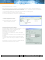
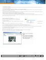
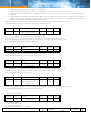
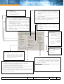
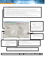
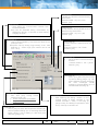
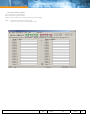
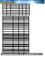
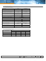
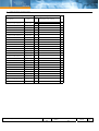
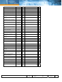
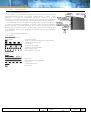
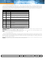
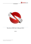
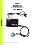
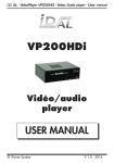
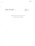
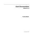
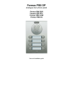
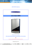
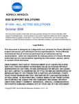
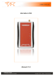
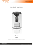
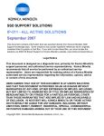
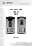
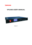
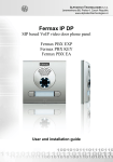
Link Door Phone All rights are reserved to Linkcom classe DR classement LinkDoor Number 001 date 15/04/05 page 1/31 Table of contents Main Description……………………………………………………………………………………………. 3 Features………………………………………………………………………………………………………. 3 Modularity of the Doorphone……………………………………………………………………………… 4 Technical characteristics of Main Module……………………………………………………………… 5 UCxN Main Module…………………………………………………………………………………………… 5 UCKN Keypad Module……………………………………………………………………………………….. 7 Doorphone assembly………………………………………………………………………………………… 7 Flush-Mounted Installation…………………………………………………………………………………. 8 Change of nameplates………………………………………………………………………………………. 8 Signaling Overview…………………………………………………………………………………………… 8 Doorphone without Keypad ……………………………………………………………………………… 9 Doorphone with Keypad…………………………………………………………………………………… 9 Programming the Doorphone……………………………………………………………………………… 13 Programming through phone(Remot Mode)…………………………………………………………… 13 Programming from PC-NSET software………………………………………………………………… 13 Description of parameters………………………………………………………………………………… 14 Programming from PC-NSET software…………………………………………………………………… 20-23 Overview of parameters………………………………………………………………………………………24 List of presseting parameters……………………………………………………………………………… 25 Technical parameters…………………………………………………………………………………………26 Electrical parameters………………………………………………………………………………………… 26 Mechanical parameters……………………………………………………………………………………… 26 Table for Easy Programming……………………………………………………………………………… 27 Dect –LinkBoxGap…………………………………………………………………………………………… 29 LinkBoxGap programming……………………………………………………………………………………30 Guarantee conditions………………………………………………………………………………………… 31 All rights are reserved to Linkcom classe DR classement LinkDoor Number 001 date 15/04/05 page 2/31 Main Description 1.1 Features: ¾ The LINK DOOR PHONE is a modular system which from a Main module (UCxN) allow to connect IP or IP WiFi camera, KEYPAD ( UCKN) and a maximum of 16 x 4 direct call button modul C4N (MASTER) or M4N (SLAVE ) total 64 buttons to manage up to 64 companies or service department by direct call ¾ Voice communication is supplied by the telephone line ( PBX, PSTN line or analog GSM Gateway ) ¾ The link between the Door Phone and the PBX can be wireless by using our device LINK BOX/Gap ¾ Mixt dialling available, TONE or PULSE ¾ Two 16 digits numbers can be programmed in each memory table for direct call button of modul C4N (Master) and M4N (Slave) (including (*, #, Flash and Pause) The first number is associated to Group 1 / DAY mode The second number is associated to Group 2 / Night mode A total of 2 x 64 numbers are associated to the 64 direct call button ¾ The numbers are associate to prefix 01 to 64 and can be dialled from the Keypad ( UCKN) ¾ Programming the numbers of ring before automatic Relaying from Groupe 1 to Groupe 2 ¾ Manual Relaying from DAY to NIGHT or NIGHT to DAY mode, from a phone or automatic Relaying when pressing again the button in case of no answering or busy line . ¾ Extending the communication between PBX and Door Phone by dialing from phone * ou # when hearing the end of conversation signal. ¾ Possibility to manage two Relays independently and by temporization for the Relay N°2. ¾ The Relaying of the 2 relays is done by dialing from the phone a prefix of 2 digits. Relay N°2 can be Relayed, based on temporization setting starting after the activation of first relay. ¾ A six digits password can be dialed from Keypad or by a combination on the first 10 Direct call Button (When Keypad is not available) ¾ Deadline parameters setting between 2 pressures on Direct call Button for password seizure. ¾ Keypad dialling mode can be done either by: -Dialling the full PSTN number or PBX extension number -By using prefix memory table of the DoorPhone (01-64) ¾ Deadline parameter between 2 calls can be programmed ¾ Flash and Pause Setting ¾ Choice between the 3 default setting tables ¾ PC setting in local mode and DTMF in Remote mode ¾ The Main module (UCxN) is Integrating heating of printed circuit ¾ Permanent lighting through visiting cards ¾ Earthing outlet for better protection against static electricity ¾ Powering the whole module in 12V AC or DC without polarity. All rights are reserved to Linkcom classe DR classement LinkDoor Number 001 date 15/04/05 page 3/31 Modularity of the DOOR PHONE - The LINK DOOR PHONE Main Module UCxN is declined in 3 types UC2N, UC1N, UC0N (equiped with 2, 1 or 0 direct call buttons) It is possible to associat to Main module UCxN the following modules IP or IP WiFi Camera module A keypad (UCKN) Up to 16 x 4 direct call buttons module C4N (Master) and M4N (Slave), by connecting behind each C4N (Master) module a M4N (Slave) module The whole DOOR PHONE can be installed Embeded or Surface mounting - UC2N UC1N UCKN Fixing frame 2 C4N (master) SMB2N-rainprotective cover UC0N M4N (slave) Flanging frame2 (flush-mounted) IP Camera WIFI Camera MK-2 Examples of frame configuration All rights are reserved to Linkcom Number 001 LINK DOOR PHONE – Installation and Operating Instructions classe DR classement LinkDoor date 15/04/05 page 4/31 WIRELESS: The gateway LINK GATE A allow connecting the Door Phone to a GSM operator. The LINK BOX/GAP module allow connecting the Door Phone wirelessly to PBX Extension or PSTN line. LINK GATE A LINK BOX GAP Technical caracteristic of Main Module UCxN Main Module The LINK Door Phone Main Module is supplied in three variants – with two buttons UC2N, one button UC1N and without buttons UC0N. Fig. 1 Rear view of Main module Fig. 2 Front view of Main module Connection 1- << LINE a b >> Allow the Main module connection to PABX Extention through wired link or through DECT link by using the LINK BOX/GAP module. It is also possible to connect the Main module to PSTN or GSM gateway line 2- << 12 V >> The LINK DOOR PHONE is powered in 12V AC or DC (no polarity required) to insure the following commands - Lighting and powering all connected modules As : IP / IP Wifi Camera / Keypad UCKN / Direct call buttons U4N and M4N All rights are reserved to Linkcom classe DR classement LinkDoor Number 001 date 15/04/05 page 5/31 - Relays Relay ON Relay OFF - Door Look - Heating Main module circuits 3 - <<1 NO COM NC / 2 NO COM NC >> 2 relays Relayable by DTMF code allow the activation of Door Look, Coaxial Camera, Light and External bell. The contact points are the following : << NO >> Open Contact (not powered constantly) << COM >> Commun Contact << NC >> Closed Contact (Permanant power for Magnetic Look) The contacts of both Relayes are galvanically isolated each other and from other Doorphone circuits. 4 - << GND>> Faston 2.8mm terminal protects against static electricity – to be connected to earthing. 5 - <<Volume>> trimmer serves to the adjustment of loudspeaker volume, it has no effect to other Doorphone features. 6 - <<MIC>> trimmer (placed under PDV board) provides the adjustment of microphone volume. Such adjustment can improve the feature of speech way, e.g. by ambient noise in the street. 7 - << HEAT >> Jumper serves the Relaying of board heating. This function requires the connection of 12V supply on "12V" marked terminal. 8 - <<Expansion>> Allow connecting by flat cable supplied any modul as IP/IP WiFi camera, Keypad UCKN, Master U4C direct call buttons. 9 - <<PRG>> Allow PC connection with KAB cable for configuration through NSET soft and serves to the diagnostics and new software load. 10 - <<SERVICE>> Jumper serves to direct access to programming. It can be used, for example by absence of password for programming. Connection diagrams: All rights are reserved to Linkcom Number 001 LINK DOOR PHONE – Installation and Operating Instructions classe DR classement LinkDoor date 15/04/05 page 6/31 Fig. 2 Examples of Relay connections 1.1.1 Extending Module with C4N(master), M4N(slave) Buttons This module is supplied in two designs. The C4N (Master) module has four buttons and includes the electronics to be connected to the Main module or to previous M4N (Slave) module. This module is only connected by flat cable – buttons and lighting through is already interconnected. M4N (Slave) module is alwaise connected behing C4N (Master) module. The connection is not prepared and should be done by conductors see on figure 3. M4N (Slave) module made of mechanical part and LEDs C4N (Master) module insure to M4N (Slave) module the electrical and commandes features 1.1.2 UCKN Keypad Module The keypad module is only connected by flat cable as well as C4N module. The only difference is that keypad module is always the last in row (no other module can be connected behind it) and it can be only linked to the first (directly to the Main module) or the second (to output of the first C4N) positions. It means that 0 to 10 buttons with direct dialing can be used instead of keypad (per assembly). The most frequent used assemblies are: – UCxN + UCKN – UCxN + C4N + UCKN – UCxN + C4N + M4N + UCKN Pay attention when programming – the position of keypad connected must be correctly specified (parameter 48). The choice is entered by gradual pressing of buttons with digits. Firstly the key symbol must be pressed to enter a password. When pressing X, the Doorphone will hang up. 1.1.3 Other modules Other modules extending the Doorphone assembly are available as Camera IP or IP WiFi. 1.2 Doorphone Assembly 1.2.1 Surface mounting : By installation on plaster only the surface mount box , with a rain protective cover SMBxN is used, which will include all mechanical parts (MKxx, Canopy xx and Fixing Frame xx). The installation is made by screwing to the wall by means of dowels. See SMB1N on figure. All rights are reserved to Linkcom classe DR classement LinkDoor Number 001 date 15/04/05 page 7/31 1.2.2 Flush-Mounted Installation The FMBBxN mounting box is built-in wall. Be careful in orientation of assembling holes when nearly MK1 square box is used – it must be in vertical axis. The well-embedded box is shown on figure. The Protecting Frame (provides overlapping of unevenness after mounting box walling-in) and Canopy (necessary for installation in external areas) form other accessories for flush-mounted installation. When installed in surroundings with possible water condensation (temperature changes) or water spraying (rain) it is recommended to connect the jumper on Main module – heating ON. The board heating has two positive functions partly it heats up the electronics in winter at temperatures below –20°C (most details with extended temperature range has guaranteed parameters from –20°C) and partly with external installation at swift temperature changes and higher air humidity by Relayed heating no water condensation occurs on Main Doorphone board, which assures its reliable function. 1.3 Change of nameplates The first step is dismantling of a fixing frame from module, where we want to change a nameplate. It can be executed by unscrewing of two screws under plastic covers on fixing frame. When removing the fixing frame we can see two independent modules. The front part (metallic) of the button module has to be first separated from plastic part in this way that we will put off the plastic lug, ensuring the front part on the right side. Each button has its separate nameplate hold by means of plastic flag (see figure). The paper nameplates can be printed from Excel form or from Nset setting program. 1.4 Signaling Overview The LINK DOOR PHONE sends acoustic signals during operation. Another signaling can be done by means of red LED (placed under microphone hole). You can also listen the signaling samples in Nset program setting. Condition Tones Tone frequency LED Line lifting up –▄–■–▀– 425-850-1275 Line hanging up –▀–■–▄ 1275-850-425 Report after calling Command confirmation from phone –▄–■–▀– 425-850-1275 ––█–– 425 Dialing goes out glows DTMF/Pulse Call Notice about call end Entry to programming from phone Programming from phone Parameter confirmation Entry to programming from PC –■–■–■– 1275 glows –■–■–■– 850 glows ––▓–▓––––– mod. 850 glows ––█–– –■–■–■– glows 850 Programming from PC All rights are reserved to Linkcom glows goes out glows glows blinks Number 001 LINK DOOR PHONE – Installation and Operating Instructions classe DR classement LinkDoor date 15/04/05 page 8/31 Connection to line (Reset) Error (anything, if unsuitable) Empty memory (no program. numb.) –■–▄–■– –■–■–■–■–■– ■– –█–▄–■–▄– ■–▄– 1275-850-1275 blinks 425…. 850-12751700… 1.5 Functions: LINK Door phone functions are influenced partly by the modules attached (with keypad or without it) and partly by setting of parameters (see chapter “Parameter Overview”). 1.5.1 Doorphone without Keypad The Doorphone module direct call buttons (U4C and M4N) are provided with nameplates shoing names of department, name of the company or name of the persons inside the building. The incoming person will press the corresponding button, the Doorphone will lift up the line either immediately (See parameter 53) when the button pressed is not the first number of password and after period given (See parameter 55) the programmed number will be dialed out. The dialing number differs if Day/Night or Group 1/ Groupe 2 mode are selected (See parameter 47): In Day mode, the dialed number belong to memory table of parameter 1 In Night mde, the dialed number belong to memory table of parameter 2 If Day/Night mode are selected, Manualy you can Relay from Day to Night mode (See parameter 45,46) The Relaying from Day to Night mode can also be done by pressing a second time on the same button either when no one is answering the phone neither when hearing a busy tone. - If a visitor presses the button after Doorphone lifting up, so the Doorphone will hang up for a period given by parameter 54, lift up the line and dial a new number. The number choice is carried out both tone (DTMF), and pulse dialing according to parameter 41 setting. - The Relay (code lock) can be controlled by first 10 buttons of Doorphone. If the visitor at door presses buttons in such combination that meet the preprogrammed code (parameters 32-34) and the time among presses is not bigger than the set point (parameter 53), then the Doorphone will lift up and close the corresponding Relay (if set in m=1 or m=5 modes) to the period given by parameter 36 event. 38. Then it will hang up. - 1.5.2 Doorphone with Keypad The Doorphone with keypad can also include besides the keypad up to 10 buttons of direct dialing except the code lock. This one is always situated on keypad. After keypad is connected, the position, where the keypad is connected to, should be set (parameter 48). The keypad has two functional buttons – key symbol = once pressing the numerical combination is considered as the combination for control of the Relayes. The second button – –X symbol = when pressing the Doorphone immediately will hang up. The number selection on keypad can be executed in two ways (parameter 49): - The incoming person is dialing number as to be done on phone – the period among button presses should be lower than the value given by parameter 53. After this period the Doorphone will lift up and dial the given number. - On buttons the incoming person is dialing a two-digit number (from 01 to 64), which represents the memory number, where the 16-digit number is stored (same as for buttons). The number dialing is managed by Day/Night setting or mode for two groups of numbers . All rights are reserved to Linkcom classe DR classement LinkDoor Number 001 date 15/04/05 page 9/31 Wifi / IP Camera Set up the wireless connection – Windows Before the doorphone with Wi-Fi camera can connect to an encrypted wireless network, the wireless settings in the camera must be configured and an IP address must be set. This is done by connecting the camera to a computer with the help of the supplied USB cable. Follow the instructions below. 1. Connect the power adapter to the camera. Press the power cable into the cable clip on the rear panel. This will prevent accidental cable disconnection. 2. Connect the USB cable to your computer and then to the camera. 3. Open My Computer and the camera should be displayed as a new drive 4. Click on the drive for the camera to see the files contained in the camera. 5. Click on the file setup.exe. This starts the AXIS Setup Tool, which lets you configure the wireless settings. See the online help in the setup tool for more information. Note that you should first configure your wireless access point and then duplicate those settings in the camera settings. 6. Specify the type of IP address to use. Seethe online help for more information. For easiest access to the camera – we recommended to use static IP address. IP address have to be from the same IP range as Wifi network. 7. Click OK, close the AXIS Setup Tool and disconnect the USB cable. 8. Wait at least 10 seconds for the settings to take effect and then restart the camera ( disconnect a power supply ) All rights are reserved to Linkcom classe DR classement LinkDoor Number 001 date 15/04/05 page 10/31 Accessing the camera If you set the IP address manually, you can now access the camera’s web interface simply by starting a browser and entering the IP address. If you selected Obtain IP address via DHCP, you have several options: • Reconnect the USB cable, browse to the camera as before, and restart the AXIS Setup Tool. The DHCP-assigned address will be displayed in the tool. • If you are using e.g. a home broadband router, you may find it convenient to view the router’s administration pages to discover which IP address has been assigned to your camera. Please consult the router’s documentation for further information. • If your network uses automatic IP addressing (DHCP) and your computer uses the UPnPTM service, the camera will automatically be detected and displayed on your screen. (UPnPTM isa certification mark of the UPnPTM Implementers Corporation.) Set the language and password When accessing the camera for the first time, the language can be changed and the “root” password must be configured. 1. Select the language from the available options, by clicking the appropriate flag. 2. Now enter a password and then re-enter it to confirm the spelling. Click OK. 3. The ‘Enter Network Password’ dialog will appear. Enter the User name: root Note: The default administrator user name root is permanent and cannot be deleted. 4. Enter the password as set in step 2 above, and click OK. If the password is lost, the camera must be reset to the factory default settings. See below. 5. If required, click Yes to install the AXIS Media Control (AMC). You will need administrator rights on the computer to do this. 6. The Live View page of the camera is displayed, with links to the Setup tools that enable you to customize the camera to your specific needs. All rights are reserved to Linkcom classe DR classement LinkDoor Number 001 date 15/04/05 page 11/31 Setup on other operating systems To set up the camera on other operating systems (Linux/Unix/Mac), follow these steps: 1. Connect the camera to the computer via the USB cable. This allows you to access the camera as a USB Mass Storage device. 2. Browse to and open the file config.txt and enter the encryption keys, the SSID network name, the IP address, etc. The wireless settings entered here should be identical to those previously configured in your wireless access point. 3. Save the file, wait at least 10 seconds for the settings to take effect and then restart the camera to enable the wireless connection. Resetting to the Factory Default Settings This will reset all parameters, including the IP address, to the Factory Default settings: 1. Disconnect the power cable. 2. Press and hold the Control button (rear panel) and reconnect the power cable. 3. Keep the button pressed until the Status Indicator displays yellow (this may take up to 15 seconds), then release the button. 4. When the Status indicator displays green (which can take up to 1 minute) the camera is reset to the factory default settings. All rights are reserved to Linkcom classe DR classement LinkDoor Number 001 date 15/04/05 page 12/31 2 Programming the Doorphone 2.1 Programming through Phone (Remot mode) 2 Ways 1. To enter the programming mode, call the Door Phone and when hearing the tone dial # 9 followed by the password 0000 by default ( See parameter 44 ) 2. by "SERVICE" jumper ( See Main module connection chapter) call the Door Phone you hear directly the programming mode tone allowing you entering in programming mode directly. 2.2 Programming from PC –Nset software To Doorphone’s setup by means of personal computer (PC) the special KAB cable to serial port and Nset program should be available and the Doorphone has to be connected to phone line. Procedure: 1) Connect the UCxN to the line (PBX, PSTN or GSM Gateway) 2) Line the Main module of the Doorphone with PC by KAB cable (Option) if PC serial port is absent, the USBCOM reduction is to be used. The Doorphone will answer and LED light on the front panel will light. 3) Run the Nset program 4) Program the Door Phone through Nset software 5) Transfer from PC to Door Phone Main module programmed sequences Transfer Status is displayed on your computer If connection is lost, it is necessary to disconnect and connect back KAB cable All rights are reserved to Linkcom classe DR classement LinkDoor Number 001 date 15/04/05 page 13/31 Description of Parameters 2.3 Direct Dialing – Memories Parameter Value Meaning Main Exam.1 Exam.2 No. nn under button tt Max 16 Digits Day/Groupe 1 mode tt – Button number (memory), always set in two-digit from [01-64] nn – telephone number max 16 digits, The numbers stored in parameter 1 are the number associated to Groupe 1 and Day mode 1 tt nn… Parameter Value Meaning Main Exam.1 Exam.2 No. nn under button tt Max 16 Digits Night/Groupe 2 mode tt – Button number (memory), always set in two-digit from [01-64] nn – telephone number max 16 digits, The numbers stored in parameter 2 are the number associated to Groupe 2 and Night mode Note : Data will be saved in the Door Phone even when PSTN line is disconnected 2 tt nn… Parameter list in relation with this feature: 41 45 46 47 48 49 57 58 59 50 81 82 2.4 Relays Parameter 31 Value Meaning rm Relaying mode Main Exam.1 11 21 Exam.2 11 22 11 25 r – m – m=1 m=2 m=3 Relay number [1-2] Relay mode [for r=1 1-4 , for r=2 1-5] Relay mode – Relay will be activated for ss period (used for electrical locks, gate opening etc.) camera mode – Relay will be activated on Door Phone lifting up and desactivating by hanging up. lighting mode – Relay will be activated on Door Phone lifting up and stay activated even for ss period after Doorphone hanging up (the line is engaged for this period). m=4 Relay mode – Relay will be activated when Door Phone button is being presseed and desactivate after ss period (used for e.g. external bell or horn connections). m=5 Temporised activation mode – This mode is available only for Relay N°2 . Relay N° 2 will be activated only after a setting period begening after the activation of Relay N° 1 List of related parameters: 32 33 34 35 36 37 38 8# 83 r Parameter Value 32 r hhhhhh 33 r hhhhhh 34 r hhhhhh Meaning Password in mode DAY + NIGHT Password in mode DAY Password in mode NIGHT Main Exam.1 Exam.2 - 1 121 2 122 1 4561 2 4562 - - - - - - r – Relay number [1-2] hhhhhh – password for relay activation when dialed from Direct Call buttons (C4N and M4N) or keypad [2 to 6 digits] Total of 6 passwords can be programmed; they are controlled by Day/Night mode. the combination is entered either by Doorphone Direct call buttons (first 10 buttons) or from attached keypad (after pressing of key symbol). All rights are reserved to Linkcom classe DR classement LinkDoor Number 001 date 15/04/05 page 14/31 By password choice some rules have to be observed: Select passwords in way not to find its combination out from wear of certain direct call buttons. Select the first password from frequentless button for direct dialing (-extends choice time)(-not valid for keypad). Pay attention to password choice numbers when one password includes other one, e.g. Relay 1 has 1234 and Relay 2 has 12345. Then after pressing button 4 the only Relay 1 is activated, but password choice 234 for Relay 2 can activate both Relays after pressing digit 5. Note: The Relay over to Day/Night mode remains set in Doorphone even after line disconnection. List of related parameters: 31 35 36 37 38 45 46 47 48 49 53 8# 83 Parameter Value Meaning Main Exam.1 Exam.2 Command aa from phone 155 266 155 266 155 266 after r Relay activation r – Relay number [1-2] aa – Prefix dialled from phone to activate Relay [2 digits]. The same prefix can be set for both Relays, then they are activated at the same time. It is recommanded to set the same prefix for Doorphone hanging up (parameter 43) aa=bb. List of related parameters: 31 36 37 38 43 8# 83 35 r aa Parameter Value 36 Meaning r ss Relay time activation Main Exam.1 Exam.2 105 205 102 202 105 205 r – Relay number [1-2] ss – duration of Relay activation [2 digits 01-99] in second List of related parameters: 31 32 33 34 35 37 38 8# 83 Parameter 37 Value rp Meaning Allow communication to Doorphone Main 11 21 Exam.1 Exam.2 11 21 11 21 r – Relay number [1-2] p – Parameter, if p=1 allowed or p=0 prohibited to control the Relay during incoming call. Allow the control of Relays when the call is made from PBX to Door Phone List of related parameters: 31 35 8# 83 Parameter Value Meaning Main Exam.1 Exam.2 Stend by time before 10 10 15 activating Relay 2 from Realy 1[s] xx – time between the activation of Relay 1 and starting the activation of Relay 2 Mode 5 have to be selected for Relay 2 in RELAYS Parameter m=5 mode setting [2 digits 01-99] List of related parameters: 31 32 33 34 35 36 37 8# 83 38 xx 2.5 Main Parameters Parameter 41 Value Meaning v Dialling mode Tone or Pulse Main 0 Exam.1 Exam.2 0 0 v – Dialing mode v = 0 Tone (DTMF) mode, v = 1 Pulse (DC) mode List of related parameters: 1 2 8# 84 All rights are reserved to Linkcom classe DR classement LinkDoor Number 001 date 15/04/05 page 15/31 Parameter 42 Value z Meaning Main Extend conversation * Exam.1 Exam.2 * * z – Sign for call extension * or # (10 sec before call end the Doorphone will send a signal, then the call may be extended by dialing either * or # ) List of related parameters: 52 8# 84 Parameter 43 Value g bb Meaning Main Hanging from phone 155 266 Exam.1 Exam.2 155 244 155 244 g – Relay [1-2] (two commands in order to hang up the Doorphone using both Relays) bb – command for Doorphone hanging up from phone [2 digits] It is recommanded to set the same prefix for Doorphone Relay activating (parameter 35) aa=bb. List of related parameters: 35 8# 84 Parameter 44 Value xxxx Meaning Main Password for Remote 0000 Exam.1 Exam.2 0000 0000 xxxx – Password for remote mode programming List of related parameters: 8# 84 Parameter Value Meaning Main Exam.1 Exam.2 45 dd Switch on Day mode 11 11 11 46 nn Switch on Night mode 10 10 10 dd – Prefix for DAY mode switching [2 digits] nn – Prefix for NIGHT mode switching [2 digits] Note: The Relay over Day/Night mode remains set in Doorphone even after line disconnection. List of related parameters: 1 2 33 34 47 8# 84 Parameter Value Meaning Main Exam.1 Exam.2 Mode of dial numbers Group 1 / Group 2 1 1 0 Day / Night e – e = 0 selected numbers from Group 1/Group 2 mode. Door phone will switch automatically from Group 1 to Group 2 numbering plan when numbers of rings set in parameter 84 is riched e = 1 selected numbers from Day/Night mode. Door phone will wait for a manual switching from Day to Night mode numbering plan or when the same buttons is redialled. List of related parameters: 1 2 8# 84 ATTENTION !! This parameter setting will sharply influence the dialing. 47 Parameter 48 e Value Meaning c Main Keypad position 0 Exam.1 Exam.2 0 1 c – c = 0 No keypad connected to the Main module c = 1 keypad UCKN connected on the first position c = 2 keypad UCKN connected on the second position c = 3 Keypad UCKN connected on third position ATTENTION !! This parameter setting will sharply influence whole Doorphone function. List of related parameters: 1 2 32 33 34 47 49 53 8# 84 Parameter 49 Value Meaning o All rights are reserved to Linkcom Main Keypad Mode 0 Exam.1 Exam.2 1 0 Number 001 LINK DOOR PHONE – Installation and Operating Instructions classe DR classement LinkDoor date 15/04/05 page 16/31 o – o = 0 dialing as on normal phone (all number of called person should be dialled on keypad). o =1 Only 2-digit from memory tablevare dialed on keypad ATTENTION !! This parameter setting will sharply influence keypad function. List of related parameters: 1 2 47 48 53 8# 84 2.6 Time Parameters Parameter Value Meaning Main Exam.1 Exam.2 Number of ring until door 2 1 2 phone pickup q – Laps of time signaled by tone before the Door Phone pick up the line Doorphone lifts up among rings namely 2 sec. after detection q – times rings (The number can be set from 1 to 9) List of related parameters: 44 8# 85 51 Parameter 52 q Value d Meaning Maximum call duration Main 2 Exam.1 Exam.2 2 1 d – Time setting for communication between Door Phone and PBX Time can be extended during conversation by dialing from phone (* or #) before or when hearing hanging up signal List of related parameters: 42 8# 85 Parameter Value Meaning Main Exam.1 Exam.2 Time between press 2 2 2 buttons for password w – max. time [sec] among button presses [range 1-9] Direct Call Buttons (U4N,M4N) - Relay activation – if time between two pressed Direct Call Buttons (C4N or M4N) is bigger than w time, the password is not evaluated correctly. - Password Dialing – if the button pressed, is the first password number for Relay activation, first digit will be associated to w time. Keypad UCKN - Relay activation – if time between two pressed digits is bigger than w time, the code is not evaluated correctly. - Dialing as on a phone, if time after pressed button is bigger than w time, then the dialing starts. If the number is incomplete, it is necessary to hang up by pressing (X button) and then dial again. - Dialing from memory table, if time following the first pressed button is longer than w time, then the entry of memory number has to be repeated. List of related parameters: 1 2 32 33 34 47 48 49 8# 85 53 Parameter w Value Meaning Main Exam.1 Exam.2 Hangup Time before 2 2 2 redial[s] z – time in [sec] for which the Doorphone will hang up, before repeated dialing (ex: re-activating direct call button during a call or dialing or after busy tone detection) [range 1-5] List of related parameters: 8# 85 54 Parameter z Value Meaning Main Exam.1 Exam.2 Time for initiation dialing 1 1 1 [s] z – time in [sec] after Doorphone lifting up before dialing [range 1-5]. This time is different for each exchange, but most exchanges usually manage to process dialing up to 2 seconds after line lifting up. List of related parameters: 8# 85 55 z All rights are reserved to Linkcom classe DR classement LinkDoor Number 001 date 15/04/05 page 17/31 Parameter Value Meaning Main Exam.1 Exam.2 Number of ring until 12 12 12 allowed h – After finishing the dialing, number of KVT (ringing tones) is being counted. If the number exceeds h value, it will hang up [range 04-99]. The dialing is repeated in case Group 1/Group 2 has been set. List of related parameters: 47 8# 85 56 h Parameter Value Meaning Main Exam.1 Exam.2 5 5 5 (100ms) (100ms) (100ms) 5 5 5 58 m DTMF Space Duration (100ms) (100ms) (100ms) 1 1 1 59 f Flash Duration (100ms) (100ms) (100ms) Pause Duration / 8 8 8 50 p internumber spaces dial (800ms) (800ms) (800ms) t – DTMF tone duration is determined by the formula: entered number + 5) x 10 = tone duration [ms] [range 1-0 i.e. 60-150ms] m – Gap duration among DTMF tones is determined by the formula: entered number + 5) x 10 = gap duration [ms] [range 1-0 i.e. 60-150ms] f – Flash duration is determined by the formula: entered number x 100 = Flash duration [ms] [range 1-6 i.e. 100-600ms] p – Pause duration is determined by the formula: entered number x 100 = pause duration [ms] [range 5-0 i.e. 500-1000ms] P – Time is simultaneously the duration of interdigit gap at pulse dialing. 57 t DTMF Tone Duration List of related parameters: 1 2 41 8# 85 2.7 Presetting and Deleting Parameter Value Meaning Main 8# # Main setting 8# 1 Setting per exam. 1 8# 2 Setting per exam. 2 Exam.1 Exam.2 executes executes executes This setting does not influence 1 and 2 (numbers stored in memory) Parameter Value 81 82 83 84 85 Meaning Main deletes all numbers in Group 1/Day mode deletes all numbers in Group 2 /Night mode Main setting only for parameters 3x Main setting only for parameters 4x Main setting only for parameters 5x All rights are reserved to Linkcom Exam.1 Exam.2 only 3.. only 4.. only 5.. Number 001 LINK DOOR PHONE – Installation and Operating Instructions classe DR classement LinkDoor date 15/04/05 page 18/31 The parameters 81 and 82 will delete all numbers stored in memory table of Group 1/ Day mode and Group 2/Night mode. The parameters 83 – 85 will execute a selective Main setting only for parameters starting with 3.. – 5.. ATTENTION !!! the deleting is non-reversible !!!, It is then necessary to program it again. 2.8 Remote Programming Termination Parameter Value Meaning Main Exam.1 Exam.2 E N D of Remote programming After dialing remotely the digit 9 the Door phone will hung up. 9 2.9 System Setting Parameter Value Meaning Main Exam.1 Exam.2 Number of buttons not used < 2 s = 0 Main module is fitted with 2 buttons as standard s = 1 Main module is fitted with 1 button s = 2 Main module is feeted with no button S0 setting is a factory one, no service can change it and so it is recommended not to change this parameter. Note: In remote mode the value of this parameter is checked and if not satisfactory form unknown reasons, so it is set up to s = 0 (fitted with 2 buttons). Atention !!! This parameter does not mainally affect the correct function of Doorphone. 6# s All rights are reserved to Linkcom classe DR classement LinkDoor Number 001 date 15/04/05 page 19/31 Parameter 43 g – command order [1-2] (two commands in order to hang up the Doorphone using both Relayes) bb – command for Doorphone hanging up from phone [2 digits] The advantage is to set the same command both for Relay activation (parameter 35) and command Doorphone hanging up aa=bb. Parameter 41. v – Dialing mode v = 0 Tone (DTMF) mode, v = 1 Pulse (DC) mode Parameter 47 e – e = 0 selected numbers from Group 1/Group 2 mode. Door phone will switch automatically from Group 1 to Group 2 numbering plan when numbers of ring set in parameter 84 is riched e = 1 selected numbers from Day/Night mode. Door phone will wait for a manual switching from Day to Night mode numbering plan or when the same buttons is redialled. Parameter 45 et 46 dd – Prefix for DAY mode switching [2 digits] nn – Prefix for NIGHT mode switching [2 digits] Parameter 48 c – c = 0 No keypad connected to the Main module c = 1 keypad UCKN connected on the first position c = 2 keypad UCKN connected on the second position c = 3 Keypad Parameter 44 xxxx – Password for remote mode programming Parameter 42 z – Sign for call extension * or # (10sec before call end the Doorphone will send a signal, then the call may be extended by dialing either * or #) Parameter 6# s = 0 Main module is fitted with 2 buttons as standard s = 1 Main module is fitted with 1 button s = 2 Main module is feeted with no button S0 setting is a factory one, no service can change it and so it is recommended not to change this parameter. Note: In remote mode the value of this parameter is checked and if not satisfactory form unknown reasons, so it is set up to s = 0 (fitted with 2 buttons). All rights are reserved to Linkcom classe DR Parameter 49 o – o = 0 dialing as on normal phone (all number of called person should be dialled on keypad). o =1 Only 2-digit from memory tablevare dialed on keypad ATTENTION !! This parameter setting will sharply influence keypad function classement LinkDoor Number 001 date 15/04/05 page 20/31 Parameter 31 r – Relay number [1-2] m – Relay mode [for r=1 1-4 , for r=2 1-5] m=1 Relay mode – Relay will be activated for ss period (used for electrical locks, gate opening etc.) m=2 camera mode – Relay will be activated on Door Phone lifting up and desactivating by hanging up. m=3 lighting mode – Relay will be activated on Door Phone lifting up and stay activated even for ss period after Doorphone hanging up (the line is engaged for this period). m=4 Relay mode – Relay will be activated when Door Phone button is being presseed and desactivate after ss period (used for e.g. external bell or horn connections). m=5 Temporised activation mode – This mode is available only for Relay N°2 . Relay N° 2 will be activated only after a setting period begening after the activation of Relay N° 1 Parameter 43 g – Relay [1-2] (two commands in order to hang up the Doorphone using both Relayes) bb – command for Doorphone hanging up from phone [2 digits] It is recommanded to set the same prefix for Doorphone Relay activating (parameter 35) aa=bb Parameter 36 r – Relay number [1-2] ss – duration of Relay activation [2 digits 01-99] in second Parameter 32,33 and 34 r – Relay number [1-2] hhhhhh – password for relay activation when dialed from Direct Call buttons (C4N and M4N) or keypad [2 to 6 digits] Parameter 38 xx – time between the activation of Relay 1 and starting the activation of Relay 2 Mode 5 have to be selected for Relay 2 in RELAYS Parameter m=5 mode setting [2 digits 01-99] r – Relay number [1-2] p – Parameter, if p=1 allowed or p=0 prohibited to control the Relay during incoming call. Allow the control of Relays when the call is made from PABX to Door Phone All rights are reserved to Linkcom classe DR classement LinkDoor Number 001 date 15/04/05 page 21/31 Parameter 57 t–DTMF tone duration is determined by the formula: entered number + 5) x 10 = tone duration [ms] Parameter 52 d – Time setting for communication between Door Phone and PABX Time can be extended during conversation by dialing from phone (* or #) befor or when hearing hanging up signal Parameter 58 m–Gap duration among DTMF tones is determined by the formula: entered number + 5) x 10 = gap duration [ms] Parameter 51 q – Laps of time signaled by tone befor the Door Phone pick up the line Doorphone lifts up among rings namely 2 sec. after detection q – times rings (The number can be set from 1 to 9) Parameter 59 f–Flash duration is determined by the formula: entered number x 100 = Flash duration [ms] Parameter 50 p – pause duration is determined per formula: entered number x 100 = pause duration [ms] Parameter 55 z – time in [sec] after Doorphone lifting up before dialing [range 1-5]. This time is different for each exchange, but most exchanges usually manage to process dialing up to 2 seconds after line lifting up. Parameter 53 w – max. time [sec] among button presses [range 1-9] Direct Call Buttons (U4N,M4N) Keypad UCKN Parameter 56 h – After finishing the dialing, number of KVT (ringing tones) is being counted. If the number exceeds h value, it will hang up [range 04-99]. The dialing is repeated in case Group 1/Group 2 has been set. Parameter 54 z – time in [sec] for which the Doorphone will hang up, before repeated dialing (ex: re-activating direct call button during a call or dialing or after busy tone detection) [range 1-5] All rights are reserved to Linkcom classe DR classement LinkDoor Number 001 date 15/04/05 page 22/31 Direcotry memory table : The two groups are quite distinct: Group 1/Day and groups 2/Night Wright inmemory table (01 to 64) a number with max 16 digits. Either : 1 number for the Group 1/Day mode And a second number for the 2/Nignt mode All rights are reserved to Linkcom classe DR classement LinkDoor Number 001 date 15/04/05 page 23/31 Overview of Parameters Parameter Value Meaning Main Exam.1 Exam.2 1 tt nn… No. nn under button tt - - - 2 tt nn… No. nn under button tt - - - 31 rm 32 33 34 35 36 37 38 Relay mode 11 21 11 22 11 25 Password in mode 1 121 1 4561 r hhhhhh DAY + NIGHT 2 122 2 4562 Password in mode r hhhhhh DAY Password in mode r hhhhhh Night Command aa from r aa 155 266 155 266 155 266 phone after r Relay activation r ss Relay time activation 105 205 102 202 105 205 Allow communication to rp 11 21 11 21 11 21 Doorphone Stend by time before xx 10 10 15 activating Relay 2 from Realy 1[s] 41 v Dialling mode 0 0 0 42 z Extend conversation * * * 43 g bb Hanging from phone 155 266 44 xxxx Password 0000 0000 0000 45 dd Code Relay on Day 11 11 11 46 nn Code Relay on Night 10 10 10 47 e Mode of dial numbers 0 1 0 48 c keypad position 0 0 1 49 o Mode Keypad 0 1 0 51 q 2 1 2 52 d 2 2 1 53 w 2 2 2 54 z 2 2 2 55 z 1 1 1 56 h 12 12 12 57 t 58 m 59 f Duration Flash dial 50 p 8# 8# Number rings until doorinterface pickup Maximum call duration Time between press buttons Time hangup before redial[s] Time for initiation dialing [s] number ring until redial (outgoing call) Duration tone DTMF dial Duration space DTMF dial 155 244 155 244 5 (100ms) 5 (100ms) 1 (100ms) 5 5 (100ms) (100ms) 5 5 (100ms) (100ms) 1 1 (100ms) (100ms) Duration pause / internumber spaces dial 8 (800ms) 8 8 (800ms) (800ms) # Main setting executes 1 Setting per exam. 1 All rights are reserved to Linkcom executes classe DR classement LinkDoor Number 001 date 15/04/05 page 24/31 8# 81 82 83 84 85 2 Setting per exam. 2 deletes all numbers in group 1 (Day mode) deletes all numbers in group 2 (Night mode) Main setting only for parameters 3x Main setting only for parameters 4x Main setting only for parameters 5x 9 executes only 3.. only 4.. only 5.. END 2.10 List of Presetting Parameters parameter Relay mode 1 Relay mode 2 Password in mode DAY + NIGHT relay 1 Password in mode DAY + NIGHT relay 2 Password in mode Day 1 Password in mode Day 2 Password in mode Night 1 Password in mode Night 2 Hanging from phone (code for hung-up 1) Hanging from phone (code for hung-up 2) Stend by time before activating Relay 2 from Relay 1[sec] Allow communication to Doorphone choice Extend conversation Hanging from phone 1/2 Password Code Relay on Day Code Relay on Night Mode of dial numbers Keypad position Mode Keypad Number ring until doorinterface pickup Maximum call duration Time between press buttons Time hangup before redial[s] Time for initiation dialing [s] Number ring until redial (outgoing call) Duration tone DTMF dial Duration tone DTMF dial Duration Flash dial Duration pause / internumber spaces dial All rights are reserved to Linkcom bas. cast. lock m=1 lock m=1 example 1 lock m=1 camera m=2 example 2 lock m=1 prog. m=5 not 121 4561 not 122 4562 not not not not not not not not not not not not 55 55 55 66 66 66 5 sec 2 sec 5 sec allowed allowed allowed DTMF * 55 / 66 0000 11 10 2 groups no DTMF * 55 / 44 0000 11 10 Day/Night no memory numbers DTMF * 55 / 44 0000 11 10 2 groups on 1st place 2 1 2 2 min 2 sec 2 sec 1 sec 2 min 2 sec 2 sec 1 sec 1 min 2 sec 2 sec 1 sec 12 12 12 100ms 100ms 100ms 100ms 100ms 100ms 100ms 100ms 100ms 800ms 800ms 800ms dialing classe DR dialing classement LinkDoor Number 001 date 15/04/05 page 25/31 3 Technical Parameters 3.1 Electrical Parameters Parameter Minimum line current Minimum line voltage Voltage on line while Doorphone answers (VA characteristics) Leakage in hang up status Impedance of line termination Band width Impedance of ringing Sensitivity of ringing detector Pulse choice Tone choice level Tone choice sensitivity Sensitivity of tone detector Power supply of lighting through, Relayes and heating Max. consumption of lighting through and heating Max. voltage of Relay contact Max. current of Relay contact Operational temperature Value Conditions 18mA line answered 18V line hang up < 8V I = 20mA < 12V I = 60 mA < 50uA U = 60V 130R + line answered 820R paral. 220n 300Hz – 3400 Hz 20 - 60mA > 2Kohm 25 – 60 Hz min. 10 – 25 V 40 / 60 ms 4 a 6 dB 20 – 60 mA 40 dB 20 – 60 mA 30 dB 20 – 60 mA 12Vss ± 2V , 10-12Vst ± 2V 300mA 48V 2A 12Vss at I < 1A at U < 30 V - 20 to + 50°C 3.2 Mechanical dimensions Type of item MKxx mount. box KPDxx (on plast.)1col. KPDxx (on plast.)2col. Canopy xx Fixing frame 1 module 114x118x45 151x157x79 149x151x49 147x151x3 All rights are reserved to Linkcom dimensions HxWxD [mm] 2 modules 3 modules 204x118x45 294x118x45 241x157x79 331x157x79 241x286x79 241x151x49 331x151x49 239x151x3 299x151x3 4 modules 384x118x45 421x157x79 421x286x79 421x151x49 399x151x3 Number 001 LINK DOOR PHONE – Installation and Operating Instructions classe DR classement LinkDoor date 15/04/05 page 26/31 4 Table for Easy Programming Meaning Programming sequence Description Spec. par. Complete your values num . of poin t Number under button 1 Number under button 2 Number under button 3 Number under button 4 Number under button 5 Number under button 6 Number under button 7 Number under button 8 Number under button 9 Number under button 10 Number under button 11 Number under button 12 Day/1gr. Day/1gr. Day/1gr. Day/1gr. Day/1gr. Day/1gr. Day/1gr. Day/1gr. Day/1gr. Day/1gr. Day/1gr. Day/1gr. 101 102 103 104 105 106 107 108 109 110 111 112 16 16 16 16 16 16 16 16 16 16 16 16 Number under button 1 Number under button 2 Number under button 3 Number under button 4 Number under button 5 Number under button 6 Number under button 7 Number under button 8 Number under button 9 Number under button 10 Number under button 11 Number under button 12 Night/2gr. Night/2gr. Night/2gr. Night/2gr. Night/2gr. Night/2gr. Night/2gr. Night/2gr. Night/2gr. Night/2gr. Night/2gr. Night/2gr. 201 202 203 204 205 206 207 208 209 210 211 212 16 16 16 16 16 16 16 16 16 16 16 16 m=1 - 4 m=1 - 5 311 312 1 1 Relay 1 works in mode Relay 2 works in mode All rights are reserved to Linkcom classe DR classement LinkDoor Number 001 date 15/04/05 page 27/31 Password for Relay 1 Day+Night Password for Relay 2 Day+Night Password for Relay 1 Day Password for Relay 2 Day Password for Relay 1 Night Password for Relay 2 Night Clos. of Relay 1 fr. phone Clos. of Relay 2 fr. phone Activation time of Relay [sec] 1 Activation time of Relay [sec] 2 Sw. cont.1 by incoming 1/0 call Sw. cont.2 by incoming 1/0 call Time between 1 and 2 [sec] Relay activation Tone/pulse tone choice 1/0 Sign of call extension */# DES hang. up from 1. phone DES hang. up from 2. phone Service password Comm. to DAY Relaying Comm. to NIGHT Relaying DES choice mode 1/0 Keypad connection 0/1/2 Keypad mode 1/0 Number of rings for ringing Maximum call duration [min] Time among button [sec] press. Hang. up time when [sec] dialing repeated Time before dialing start [sec] Num. of rings bef. hang. up Duration of dialing tone (n+5)x10 Gap among DTMF tones (n+5)x10 Flash duration nx100 Pause durat. / interdigit nx100 gap All rights are reserved to Linkcom 321 322 331 332 341 342 6 6 6 6 6 6 351 2 352 2 361 2 362 2 371 1 372 1 38 2 41 42 1 1 431 2 432 2 44 45 4 2 46 2 47 48 49 1 1 1 51 1 52 2 53 1 54 1 55 1 56 2 57 58 59 ms ms ms 1 1 1 50 ms 1 Number 001 LINK DOOR PHONE – Installation and Operating Instructions classe DR classement LinkDoor date 15/04/05 page 28/31 5 DECT – LINK BOX/Gap 5.1 LINK BOX/Gap Description This module is a separate box allowing the connection of an analog telecommunication device to wireless system DECT – GAP . LINK BOX/Gap is suitable for Doorphone connection, because it is not necessary to place the conductors from house to the gate and to address to base station is enough sufficient. All Doorphone features are reserved. LINK BOX/Gap must be energized to power supply and the Doorphone s to outputs of analog line (indicated on figure) – both outputs of analogue line are parallel. The LINK BOX/Gap 300 contains an internal antenna allowing the connection of 300 m direct visibility and 50 m in building. The LINK BOX/Gap 5000 can be fitted with an external antenna increasing the range to 6 km. 5.2 LINK BOX/Gap Signaling LED indication | Time interval is 8sec | Relayed off - no power supply - ready to use and addressed to base station - incoming searching call - connection - programming mode - searching for base station - base station found - base station not found Tones - dial tone - special dial tone (modulated) - busy tone - confirmation tone - error tone All rights are reserved to Linkcom classe DR classement LinkDoor Number 001 date 15/04/05 page 29/31 5.3 LINK BOX/Gap Programming You can enter the programming mode 20 sec – 10min after power supply ON by **9 choice (to dial/busy tones) namely after LINK BOX/Gap power supply ON. If you had entered a new PIN in previous programming (par.2) so now you must enter a correct PIN for entry to programming (following main reset (par. 90) the PIN should not be entered). The special dialing tone is heard in programming mode. The entry and correct PIN are confirmed by confirmation tone, the false PIN by error tone. Param. Value Meaning **9 [xxxx] entry to programming, xxxx=PIN, if entered 0 # log off – stored DECT parameters will be deleted 1 xxxxxxxx # entry code to base station (4-8 numbers) PIN change - xxxx is old, yyyy is new, 0000 is firm 2 xxxx yyyy # one distance – number load is multiple of 130m (300m = 3 0# - 79# 3) choice mode - 0 sends / 1 suppresses DTMF choice 40 0# / 1# transmission from base station (0 is pract. doubled choice) 41 0# / 1# operational setting - 0 is phone / 1 is FAX 70 0# / 1# / 2# call limitation - 0 not limited, 1 incoming, 2 outcoming 71 0# / 1# / 2# type of call - 0 both, 1 internal, 2 external call Flash length – xxx times 10ms (100ms = 010) 72 xxx # firm.=210ms 90 # reset and company setting (bold), presets all reset and company setting (bold), log in parameters 91 # will be kept autoreset 0-inactive / 1-active (every 24 hrs will end 92 0# / 1# all transmissions and recall to base station) Settings for use with Doorphone: (90#), 401#, 410#, 700#, 710# Internal call will be executed by **s, where s is 0-9 i.e. number of internal station, station 9 may be called 10min after power supply ON, up to this moment it is entry to programming. Note: The Relaying of call/internal query can be made by “Flash” and **s choices. The call will be Relayed over by hanging up. The “Flash” function will turn back to previous call. 5.4 Log on to Base Station The log in might be done automatically in this way that we hold the button for searching on base station (min 3sec) and then we will connect the power supply to LINK BOX/Gap. This will automatically log on to base station within 1 min and if not made it is recommended to make the company reset (90#) and repeat logging on. Setting of parameters 401#, 410#, 700#, 710# is required. Be sure about parameter 40, which is being set after company reset thus that the choice is transmissed not only by Doorphone, but also the base station so that the choice is executed twice!! All rights are reserved to Linkcom Number 001 LINK DOOR PHONE – Installation and Operating Instructions classe DR classement LinkDoor date 15/04/05 page 30/31 Guarantee conditions: The product was shop-checked. The producer guarantees that this product will keep the features described in these operating instructions in the course of guarantee provided that the user will be handled with it as described in the operating manual. The guarantee will be extended by period of possible guarantee repair. When claiming in guarantee period please contact your dealer. The producer only will make the guarantee repairs. Attach the description of claim reason, proof of purchase and your exact address to the product. The guarantee does not include: • Mechanical, thermal, chemical and other damages caused by user’s activities • Defects caused by natural disasters • Defects caused by repair or changes carried out by user or other unauthorized person • Willful damage of product • Incorrect use of product caused by other use than specified in operating manual (e.g. installation, programming) • Damages caused during product transport to customer and from supplier Producer: Dealer: Date of sale: All rights are reserved to Linkcom classe DR classement LinkDoor Number 001 date 15/04/05 page 31/31