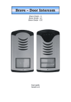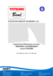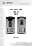
1
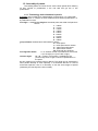
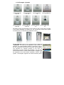
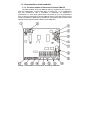
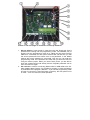
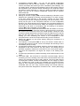
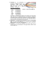
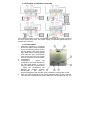
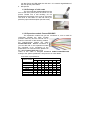
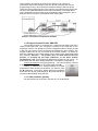
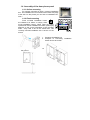
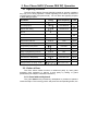
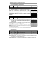
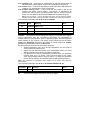
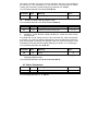
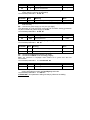
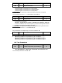
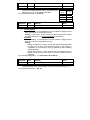
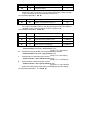
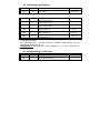
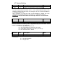
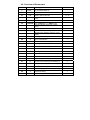
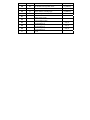
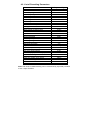
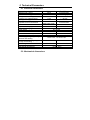
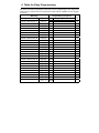
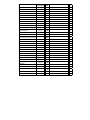
Fermax PBX DP analogue door phone panel Fermax PBX EXP Fermax PBX KEY Fermax PBX CAM Fermax PBX EA User and installation guide Welcome Congratulations on purchasing the door phone panel “Fermax PBX Door Phone” Fermax PBX DP. This door phone can satisfy your need of communication with visitors at the entrance to the building, to your company or at the entrance of your house. Its use is universal, because it can be connected to an analog internal extension line of your PBX regardless on its type or on the producer. To each pushbutton you can program up to two 16-digit numbers in pulse or tone dialling incl. characters “*”, “ # ”, Pause and Flash in tone dialling. The basic module of the door phone always contains 2 pushbuttons and optionally the first expansion, 8 pushbutton C module. The combination of Fermax New Cityline panels enable the sets of door phone with 1 to 10 pushbuttons just by using the basic electronics module of Fermax PBX DP. You can also expand the whole system by the 8 pushbutton expansion module Fermax PBX EXP up to the limit of 64 pushbuttons. The basic module can be expanded by Fermax PBX CAM, a module with IP colour camera, optionally there can be an add-on speaker module with an amplifier Fermax PBX EA, which is used for very noisy areas. The Fermax New Cityline panels are rich with an add ons. For example the panels offer installations on the surface or flush mounted, they can be used both indoors and outdoors, there can be addon roofing used, etc. The door phone panel is powered from the analog line of the PBX. The features of the door phone are similar to a hands-free telephone. Among basic features you can find the possibility of opening up to two doors via connected electrical locks (first 10 pushbuttons can be used for code lock function – opening the door via a pre-set code). Easy programming via serial line or USB from the computer, alternatively via tone dialling of a telephone. If programming via tone dialling, you can either ether the programming mode by calling to the door phone panel and enter the 4-digit service password or by connecting of programming jumper on the main board of the door phone panel. The second type of programming is used usually when you forget the service password. Manual version V8.1 6. 4.2010 Contents 1 BASIC DESCRIPTION....................................................................................... 6 1.1 FEATURES ...................................................................................................... 6 1.2 ASSEMBLY OF PANELS ................................................................................... 7 1.2.1 Terminology and orientation in panels ..................................................... 7 1.2.2 Examples of panels ................................................................................... 8 1.3 CHARACTERISTICS OF THE MODULES ........................................................... 10 1.3.1 The basic module of electronics Fermax PBX DP .................................. 10 1.3.2 Example of switches connection ............................................................. 15 1.3.3 Front panel ............................................................................................. 15 1.3.4 Exchange of visit cards ........................................................................... 16 1.3.5 Expansion module Fermax PBX EXP ..................................................... 16 1.3.6 Keypad module Fermax PBX KEY.......................................................... 17 1.3.7 Other modules (panels) ........................................................................... 17 1.4 ASSEMBLY OF THE DOOR PHONE PANEL ....................................................... 18 1.4.1 Surface mounting .................................................................................... 18 1.4.2 Flush mounting ....................................................................................... 18 2 DOOR PHONE NUDV (FERMAX PBX DP) OPERATION......................... 20 2.1 SIGNALING OVERVIEW................................................................................. 20 2.2 VISITOR AT DOOR ........................................................................................ 20 2.2.1 Guard without Keyboard ........................................................................ 20 2.2.2 Guard with Keyboard ............................................................................. 21 2.3 PERSON INSIDE OBJECT ............................................................................... 22 2.3.1 Outgoing Call ......................................................................................... 22 2.3.2 Incoming Call ......................................................................................... 22 3 PROGRAMMING OF PARAMETERS .......................................................... 23 3.1 PROGRAMMING THROUGH PHONE ................................................................ 23 3.1.1 Entry to Programming ............................................................................ 23 3.1.2 Programming of parameters ................................................................... 23 3.2 PROGRAMMING FROM PC – PROGRAM NSET................................................ 24 4 DESCRIPTION OF PARAMETERS .............................................................. 25 4.1 4.2 4.3 4.4 4.5 4.6 4.7 DIRECT DIALING – MEMORIES ..................................................................... 25 SWITCHES .................................................................................................... 25 BASIC PARAMETERS .................................................................................... 27 TIME PARAMETERS ...................................................................................... 29 PRESETTING AND DELETING ........................................................................ 32 PROGRAMMING TERMINATION ..................................................................... 32 SYSTEM SETTING ......................................................................................... 33 4.8 4.9 5 TECHNICAL PARAMETERS ........................................................................ 37 5.1 5.2 6 OVERVIEW OF PARAMETERS ........................................................................ 34 LIST OF PRESETTING PARAMETERS .............................................................. 36 ELECTRICAL PARAMETERS .......................................................................... 37 MECHANICAL DIMENSIONS .......................................................................... 37 TABLE FOR EASY PROGRAMMING .......................................................... 38 1 Basic description 1.1 Features ¾ ¾ ¾ ¾ ¾ ¾ ¾ ¾ ¾ ¾ ¾ ¾ ¾ ¾ ¾ ¾ ¾ ¾ Modular system with 1 to 64 pushbuttons Two 16-digit numbers stored on each pushbutton It can be connected to any PBX via analog line PBX DP door phone works on any analog line Compatible with all analog and hybrid types of PBXs Panel is made of highly weather resistant anodized aluminium Waterproof pushbuttons with impregnation IP66, gold plated contacts Pushbuttons are manufactured in zamak and a natural chromed finish Card slot lighting by means of low consumption, max. duration LEDs Card slot lighting can be switched off to be less attractive for vandals Flush or surface mounting 2 relays for two independent electrical locks Codelock feature by using pushbuttons Up to six codelock numerical passwords (2-6 digits) Programming via PC USB cable Remote control and programming via DTMF Optional DECT GAP BOX for wireless connection to DECT GAP base station Integrated heating of the electronic cuircuit board 1.2 Assembly of panels The building blocks of Fermax IP DP are the basic panels which differ by its size, number of pushbuttons, if the visit card has got two or one pushbuttons. 1.2.1 Terminology and orientation in panels 4 AP 204 (item number) as a representative of terminology. It is a panel with height of 199mm. It contains an audio module and two times 4 pushbuttons, i.e. 8 pushbuttons in total. first digit: 1 - 9 defines the height of the whole panel, the width of all panels is 130mm. 1 - 128mm 2 - 151mm 3 - 175mm 4 - 199mm 5 - 246mm 6 - 294mm 7 - 341mm 8 - 389mm 9 - 436mm group of letters: defines basic HW features of panel : A - audio panel C - audio panel with a camera P – panel with pushbuttons V – panel with a window W- panel with two windows first digit after letters: 1 / 2 – defines number of pushbuttons at visit card 1 (on the right) or 2 (on the left or right) next two digits: 01 - 15 – number of visit cards. If multiplied by the previous digit, then we get a number of pushbuttons on the panel By this marking one compact panel is defined. The panel can be expanded by other panels vertically or more optimally, in a horizontal direction. In case of horizontal expansion, then it is necessary to use the same height of panels (defined by the first digit of the item number). 1.2.2 Examples of panels Fermax PBX DP 1 AP 201 Fermax PBX DP 2 AP 202 Fermax PBX DP 1 AP 101 Fermax PBX DP 2 AP 201 Fermax PBX EA 1A Fermax PBX KEY 1 Fermax PBX EA Fermax PBX CAM 2A 2C All panels can be mounted either on the surface or they can be flush mounted. In the latest catalogue of Fermax you can choose the correct New Cityline accessories incl. for example the protective roofing. Fermax PBX DP panels can be equipped with an additional time switch called "TimeRelay". It is used for an expansion of the number of switches. It is programmable. Based on switching of one of the two switches in the Fermax IP DP panel, the TimeRelay can simulate e.g. sequent opening of the door or alternatively you can connect the exit button. You can also use an external DECT module called DistyBox. DistyBox can be registered to the base station operating in DECT GAP system. The DistyBox registers as another wireless phone. Please do not use systems which do not support DTMF transmission during the call from the wireless DECT phone to the other wireless DECT phone (e.g. DTMF transmission is required when you need to use the DTMF command for opening the door). DistyBox has got its own power supply. it works as a DECT to analog line convertor. The door phone panel is connected to this analogue line. 1.3 Characteristics of the modules 1.3.1 The basic module of electronics Fermax PBX DP The basic module of Fermax PBX DP panel is supplied in two versions – with two pushbuttons - Fermax PBX DP-2 (a version for 1 or 2 pushbuttons) and two pushbuttons with a possibility of expansion by additional 8 pushbuttons, i.e. each basic panel allows connection of up to 10 pushbuttons with no further accessories of Fermax PBX DP panel. The basic module can be further expanded by additional 8 pushbuttons via modules called Fermax PBX DP EXP and a keypad module called Fermax PBX KEY. Picture 1 Schematics of connection and set-up elements Picture 2 The real image of connection and set-up elements 1. Service jumper is used usually in case when the user forgets the service password for entering into the programming mode. The standard way of entering into the programming mode is by calling the line where Fermax PBX DP is connected, the door phone answers the call and then you dial the service password #xxxx where xxxx is the password. In the default settings the service password is xxxx=0000. This way you can enter the programming mode. If the password is invalid, then you have the choice of using the service jumper. When you call the door phone, you are able to enter the programming mode directly and the forgotten password can be set to the new one again. 2. PC conector is used for connecting RS232 cable or USB cable to the PC. After installing Nset program, it is possible to program or check the settings of parameters of the program. Attention – if you use the programming cable and the PC connector is used (the black connector), the door phone is out of order – it can´t be used for normal operation. 3. Loudspeaker loudness SPK – you can set the desired loudspeaker loudness/volume with the trimmer. Attention – the louder the loudspeaker volume, the sharper the switching of echo cancellation (TRH settings). You can obtain approx. 25mW from the telephone line for the acoustic output of the Handsfree circuit, therefore further increasing of the loudness volume just leads to higher distortion. In case you need to increase the volume output, you can use an extrernal loudspeaker module with an amplifier Fermax PBX EA. 4. Connection of loudspeaker SPK 5. Settings of acoustic coupling TRH is used for balancing of direction on the telephone line (outgoing-incomming voice transmission). To avoid “hooting” of the door phone because of the acoustic coupling, the door phone chooses which direction (outgoing-incomming) has got the priority, if the priority will be given to the microphone direction or to the loudspeaker direction. The sound volume level of “swtching” the microphone direction of the door phone is set with the trimmer „TRH“. The settings of this trimmer is influenced by the level of surrounding noise and setting of microphone volume „MIC“ and loudspeaker volume "SPK". Process of the set-up: please set the trimmers MIC and SPK to ¼ from the minimum sound volume (from the minimum value start turning to the left), the trimmer TRH needs to be set to the middle position. During the voice connection please speak softly and start turning the TRH trimmer to the left side until the other party on the phone side (inside the building) starts hearing you well. Increasing the volume of the loudspeaker or the microphone then can be set as required according to local conditions. 6. Please pay attention on the correct polority during the connection of a microphone MIC! 7. The loudness of microphone MIC is set by the trimmer. Please bear on mind that the louder the sound volume, the sharper the switching of echo cancellation (set-up of TRH). 8. Jumper Heat (marked as H) enables switching on/off the heating which is integrated on the main board for the door phone. The heating has got automatic regulation, therefore it works both at 12V or 24V power supply . The lower the temperature, the higher the output of the heating (max. 1,5W). 9. Jumper Light (marked as L) enables switching on/off the illumination of visit cards. 10. Connection 12V – the connector for connection of power supply, which is necessary just for the heating of the main board, for illumination of the visit cards or for controlling the coils of relay contacts. The coil of relay has got a consumption of 50mA, however the telephone line can supply e.g. 20mA only. Therefore the coils of relay are controlled from the external power supply of 12V by optrons (opto-isolators). If the power supply of 12V is not connected, then you can´t verify contacts making! The circuits inside the door phone have been designed for connection of 8V - 18VAC (alternating) 11. 12. 13. 14. or for 12V - 24VDC (direct), max. cnsumption is 250mA (+ 3,5mA x number of visit cards). Switching contact of 2nd relay (NO=normally open, NC=normally closed and COM= common terminal of the relay) Switching contact of 1st relay (NO=normally open, NC=normally closed and COM= common terminal of the relay) Grounding connector GND – it is used for antistatic protection, especially for installation at places with marble floor, or if the plastering with polystyrene is used, then there is quite often the static electricity available. By grounding the door phone panel you will avoid unneccessary problems, so we strongly suggest to use the grounding connector! Connection of the telephone line 15. Connector 8 - for connecting 8 pushbuttons (integrated expansion). For connection please use an interconnection cable Fermax PBX CC8. Each colour of the cable is assigned exactly for a specific pushbutton – see picture 3. Connection of pushbuttons: blue = 3rd pushbutton Picture 3 Cable Fermax PBX CC8 brown = 4th pushbutton yellow = 5th pushbutton red = 6th pushbutton white = 7th pushbutton green = 8th pushbutton orange = 9th pushbutton black = 10th pushbutton All numbers of pushbuttons are related to the setting of the door phone "6#0" (see more in the programming part of the manual). It means the basic panel with two pushbuttons is being used. These two pushbuttons are used pernamently on the main PCB board. In the table please deduct 1 from the number of the pushbuttons when set to 6#1 and please deduct 2 from the number of the pushbutton when set to 6#2. 16. Connector 5 – connection of the 8-pushbutton expansion Fermax PBX EXP or the keypad Fermax PBX KEY. The connection is done via Fermax PBX CC5 cable. It is a data connection only. Power supply of illumination and the common output is on the Connector 3. 17. Connector 3 - it is used for connection of the power supply and the common output of the pushbuttons. The original Fermax cable is used (Fermax PBX CC3). 1.3.2 Example of switches connection The switching contact of relay is separated galvanically from other circuits of the door phone panel. Also 12V power supply is separated galvanically from the rest of the circuits. 1.3.3 Front panel 1. Assembly openings for mounting of the front panel. After installation of the top opening, please cover it with the plastic cover with Fermax logo. When bottom opening please cover with the grey, round plastic cover. Both covers incl. the screws are part of delivery as accessories. 2. Loudspeaker 3. Pushbuttons – these two pushbuttons are firmly attached on the main PCB board. In case of using a panel with no pushbuttons , these two pushbuttons are blocked by program (param. 6#0,6#1,6#2 – see more in programming part of the manual), other pushbutton numbers are moved. 4. Visit card. The exchange of visit card is described later on in the manual. The visit card is illuminated by white LEDs (they can be switched off). You can also find a red LED under the visit card – it is used for signallisation of the door phone panel status. 5. Microphone 1.3.4 Exchange of visit cards The visit cards are disassembled from the front of the door phone panel as shown on the picture. Please use a tool carefully, do not damage the front panel or the cover of visit cards. The cover of visit cards is a tub into which you place the paper with description (the visit card). 1.3.5 Expansion module Fermax PBX EXP The expansion module has got two connectors 5, one is used for connection towards the basic module (Fermax PBX DP) and the second one is used for connection of the following module. For interconnection please use cable Fermax PBX CC5. Besides connectors 5, you can also find on the expansion module the connector 8 for connection of the pushbuttons. For interconnection please use the cable Fermax PBX CC8. Each colour of the cable is assigned Picture 4 Cable Fermax PBX CC8 exactly to the specific pushbutton, see picture 4 for more details. Connection of pushbuttons: Position number on Fermax PBX EXP Colour of wire 1 2 3 4 5 6 7 Blue 11 19 27 35 43 51 59 Brown 12 20 28 36 44 52 60 Yellow 13 21 29 37 45 53 61 Red 14 22 30 38 46 54 62 White 15 23 31 39 47 55 63 Green 16 24 32 40 48 56 64 Orange 17 25 33 41 49 57 Black 18 26 34 42 50 58 The numbering of positions is shown on the picture 5. All numbers of pushbuttons refer to the settings of the door phone panel (see more in the programming section). All numbers are related to setting of the door phone "6#0" (see the programming part of the manual). It means the basic panel uses two firmly mounted pushbuttons on the main PCB board. In the table above one is deducted from the number of the pushbbuton when setting 6#1, two is deducted from the number of pushbutton when setting 6#2. Picture 5 Connection of expansion modules 1.3.6 Keypad module Fermax PBX KEY The keypad module is connected via a cable Fermax PBX CC5 and a cable Fermax PBX CC3. The connection is similar to the connection of the expansion module. The difference is that the keypad module is always the last in the row (you cannot connect to the keypad module any other module). The keypad module can be only connected to the second position (i.e. directly to the basic module) or to the third position (to the output of the first Fermax PBX EXP module). Attention – 1st position can´t be used because the first position is occupied by the fixed expansion on the basic module (pushbuttons 3-10). This means that besides the keypad you can use 0 – 18 pushbuttons with the direct dialling (depends on the specific configuration). Please pay attention during programming – you need to specify correctly to which position the keypad is connected (parameter 48). Dialling is realised by a sequent pushing of number pushbuttons. When entering a password, you need to press the B pushbutton. To hang up, please press the pushbutton A and the door phone panel hangs up. By parameter 40 you can also enable dialling during the call. 1.3.7 Other modules (panels) All other panels can be found in the offer of your local partner. 1.4 Assembly of the door phone panel 1.4.1 Surface mounting For surface mounting we offer a compact installation box. The installation box is mounted with screws with plugs to the wall. On the picture you can find an installation box, size 1. 1.4.2 Flush mounting Flush mounted installation boxes are refered to as “MKxx” or simply “flush mount installation boxes”. When using the nearly square flush mount installation box MK1, please pay attention on the correct orientation of the mounting holes – they need to be on the vertical axis. The correctly mounted installation box is shown on the picture. 1. Preparing installation box 2. Principle of connecting boxes next to each other 3. Placing the installation box above the ground installation When installing the door phone panel in the environment where water may be condensing (temperature changes) or where it may be raining on the door phpje panel, we suggest to use the jumper on the main PCB board – turn on the heating. Main PCB board heating has got two positive functions. Firstly it warms up the electronics during winter when temperatures drop below -20°C (most components have got guaranteed parameters for temperatures up to -20°C). Secondly if you use the heating of the main PCB board, there are no water condensations on the main PCB board in case the door phone panel is installed outdoors. If the heating is used, we can guarantee correct functionality. The heating protects the main PCB board against quick changes in temperatures or when there is a higher humidity of air. 2 Door Phone NUDV (Fermax PBX DP) Operation 2.1 Signaling Overview The Door Phone NUDV (Fermax PBX DP) signals an acoustic conditions they may occur during operation. Another signaling can be done by means of red LED (placed under microphone hole). You can listen the signaling samples in Nset setting program. Condition Tones Tone frequency LED Line lifting up –▄–■–▀– 425-850-1275 glows Line hanging up –▀–■–▄ 1275-850-425 goes out Report after calling –▄–■–▀– 425-850-1275 glows ––█–– 425 Command confirmation from phone Dialing goes out DTMF/Pulse Call glows Notice about call end –■–■–■– 1275 glows Entry to programming from phone –■–■–■– 850 glows ––▓–▓––––– mod. 850 glows Programming from phone Parameter confirmation Entry to programming from PC ––█–– –■–■–■– glows 850 Programming from PC Connection to line (Reset) glows blinks –■–▄–■– 1275-850-1275 Error (anything, if unsuitable) –■–■–■–■–■–■– 425…. Empty memory (no progr. numb.) –█–▄–■–▄–■–▄– 850-1275-1700… blinks 2.2 Visitor at Door The Door Phone NUDV function is influenced partly by used guard assembly (with keyboard or without it) and partly by setting of guard parameters (see chapter “Parameter Overview”). 2.2.1 Guard without Keyboard The guard buttons are provided by nameplates or positions of persons inside the object. The incoming person will press the corresponding button, the guard will lift up the line neither immediately (the button is not the first number from code lock), or with delay (parameter 53) and after period given by parameter 55 will dial the programmed phone number. The dialing number differs by choice mode, which is set in the guard (parameter 47): - Day/night mode = being the guard in Day mode, so it is always dialing a number set in parameter 1, in Night mode, it is always dialing a number set in parameter 2. The mode switchover is set in parameters 45,46. - mode of second number group = first press – it always dials a number set in parameter 1. By repeated press of the same button or detection of busy tone after dialing the guard will select the number from the second group (parameter 2). The next press of the same button again selects a number of the first group, etc..…… If a visitor presses the button after guard lifting up, so the guard will hang up for a period given by parameter 54, lift up the line and dial a new number. The number choice is carried out both tone (DTMF), and pulse dialing according to parameter 41 setting. The switch (code lock) can be controlled by first 10 buttons of guard. If the visitor at door presses buttons in such combination that meet the preprogrammed code (parameters 32-34) and the time among presses is not bigger than the set point (parameter 53), then the guard will lift up and close the corresponding switch (if set in m=1 or m=5 modes) to the period given by parameter 36 event. 38. Then it will hang up. 2.2.2 Guard with Keyboard The guard with keyboard can also include besides the keyboard up to 18 buttons of direct dialing always behaving as to be mentioned in Chapter 2.2.1 except the code lock. This one is always situated on keyboard. After keyboard is connected, the position, where the keyboard is connected to, should be set (parameter 48). The keyboard has two functional buttons – key symbol = once pressing the numerical combination is considered as the combination for control of the switches. The second button –X symbol = when pressing the guard immediately will hang up. The number selection on keyboard can be executed in two ways (parameter 49): - The incoming person is dialing number as to be done on phone – the period among button presses should be lower than the value given by parameter 53. After this period the guard will lift up and dial the given number. - On buttons the incoming person is dialing a two-digit number (from 01 to 64), which represents the memory number, where the 16-digit - number is stored (same as for buttons). The number dialing is managed by Day/Night setting or mode for two groups of numbers (as described in Chapter 2.2.1). Version of firmware 7.8 makes it possible dial DTMF dialing during talk from keyboard. This feature it is possible switch on only by programming from phone, from PC program this feature isn't accessible and after programming door phone possibility dial from keyboard during talk is OFF. Parameter 40d - d=0 switch off (default), d=1-3 switch on dialling during talk,1= buton key dial *, 2=button key dial # and 3=button key dial “A”. 2.3 Person Inside Object The person inside object is considered a person that is in phone contact with Door Phone NUDV. 2.3.1 Outgoing Call The outgoing call is the call from guard (caused by visitor). After guard choice the telephone is ringing inside object and the lifting up will allow speaking to the visitor at door. The code choice can close the switch (parameter 35), if set to m=1 or m=5 modes, change over the Day/Night modes (parameters 45,46) and hang up (parameter 43). The guard in 10 seconds before call end (parameter 52) will send a notice about call end and the call may be extended by sign selection (parameter 42). The telephone hanging up will end the call (the exchange is sending a busy tone on guard’s line and the guard also will hang up). 2.3.2 Incoming Call The incoming call is the call from guard (caused by person inside object). After exchange number selection, where the guard is connected, the guard’s line is ringing and when set number of rings is over (parameter 51), the guard will lift up and it is possible to speak. The possibilities are the same as with outgoing call (Chapter 2.3.1). • Except the first 10 seconds, where extra "# and service password" (parameter 44) can be entered, the guard then will proceed with programming mode. • The other exception of incoming call is by connected “SERVICE” jumper. The guard after line lifting up proceeds then with programming mode (without service password). 3 Programming of Parameters 3.1 Programming through Phone 3.1.1 Entry to Programming The New Door Phone NUDV will be set to programming mode in two ways: 1. by password – only incoming call! – answer the telephone and dial a number, where the guard is lined (either branch number, if connected to branch exchange or number of state line to object, where the guard is placed and let you put through to branch directly connected with guard). The guard will answer (you hear tone for answering – see Chapter 2.1 page 20) up to 10 sec dial #xxxx, where xxxx is the service number for entry to programming and if O.K., the registration tone to programming will sound and afterwards the programming tone is heard (see Chapter 20 page 20). In basic setting is xxxx = 0000. 2. by "SERVICE" jumper – only incoming call! – you will realize the connection with guard in the same way as in art. 1, but when the SERVICE jumper is connected, then the guard after answering directly comes to programming mode – you hear tone for answering, registration tone to programming and afterwards the programming tone is heard. (see Chapter 2.1 page 20). 3.1.2 Programming of parameters The initial state for programming is signaled by programming tone and the guard will come back to this state always after time expiration (5 seconds) even you started to program anything. When programming two types of parameters will occur. Partly they are parameters with fixed length – the majority of them they are, then the programming is affirmed and the parameter is always recorded immediately after mandatory length fulfillment by acknowledge tone and partly the parameters with variable length (parameter 1,2,32,33,34), followed with confirmation and the recording of the parameter after inactivity period expires (5 sec). The only case with immediate recording of parameters is the fulfillment of max. number of recorded signs (numbers) – by parameters 1 and 2 it is 16, by parameters 32,33,34 it is 6. If during programming you enter number (sign) not allowable by its extent then the guard immediately emits an error tone, the parameter will not be recorded nor changed, the guard will come to initial state and it is possible to repeat the parameter setting or program another parameter. The guard stays inactive in programming mode for 34 seconds, then he will automatically hang up. By every dialing of DTMF tone this period is set up repeatedly. The selection of parameter 9 can also end the programming mode. Note 1. if you wish to keep the connection (extend the 34 seconds period) than the customer will think over the other setting, so pressing e.g.. 7, 0, * or # form time to time will be sufficient and the guard immediately responds by error tone, but he will extend the period to hanging up.. Note 2. The # sign is not used by entering of 32,33,34 parameters can be used for immediate parameter entering. 3.2 Programming from PC – Program Nset To guard’s setup by means of personal computer (PC) the special KAB cable to serial port and Nset program should be available and the guard has to be connected to telephone line. Procedure: - Connect the NUDV to the line - Line the guard with PC by KAB cable (if PC serial port absent, the USBCOM reduction is to be used). The guard will answer and LED light on the front panel will light. - Run the Nset program – the guard will report the his conversion to PC programming mode (viz. chapter 2.1 page 20). After Nset program being run the guard is in this mode – this status is indicated by LED light on front panel by 1 second flashing. By loss of connection it is necessary to disconnect the cable from guard and connect it again – the guar will answer and if Nset program runs he will report his conversion to programming mode. For details of setup refer to program help and on producer’s pages www.alphatech.cz. 4 Description of Parameters 4.1 Direct Dialing – Memories Parameter Value 1 tt nn… Meaning Basic No. nn under button tt - tt – Button number (memory), always set in two-digit manner [01-64] nn – telephone number up to 16 digits, we want to store. To store other choice flags the assignment given in table is mean. choice 0-9 0-9 used. # # The numbers stored in parameter 1 are the number of the first group or numbers of Day mode. * ** Neither basic setting do not change or delete the stored Flash *# numbers. Pause *0 Parameter Value 2 tt nn… Meaning Basic No. nn under button tt - tt – Button number (memory), always set in two-digit manner [01-64] nn – telephone number up to 16 digits, we want to store. To store other choice flags the assignment given in mean. choice 0-9 0-9 table is used.. # # The numbers stored in parameter 2 are the number of the second group or numbers of Night mode. * ** Neither basic setting do not change or delete the stored Flash *# numbers. Pause *0 Note: The switchover to Day/Night mode remains set in guard even after line disconnection. List of related parameters: 41 45 46 47 48 49 57 58 59 50 81 82 4.2 Switches Parameter Value 31 rm Meaning switch r works in m mode Basic 11 21 r – switch number [1-2] m – switch mode [for r=1 1-4 , for r=2 1-5] m=1 switch mode – it will close on command or password for ss period (used for electrical locks, gate opening etc.) m=2 camera mode – it will close by guard lifting up and open by hanging up. m=3 lighting mode – it will close by guard lifting up and stay closed even for ss period after guard hanging up (the line is engaged for this period). m=4 switch mode – it will close after button pressing and open after ss period (used for e.g. external bell or horn connections). m=5 gradual opening mode – in this mode the only switch 2 will be set together with switch 1 set to mode 1. The switch 1 is activated for ss period, then the time xx is proceeding before switch 2 closing. Then the switch 2 is activated for ss period and afterwards the guard hangs up. Note: The only switch 1 can be activated from phone and all sequence started. Besides that the switch 2 can be separately activated from buttons by password. List of related parameters: 32 33 34 35 36 37 38 8# 83 Parameter Value Meaning Basic passw. hhhhhh for switch r in DAY + 32 r hhhhhh NIGHT mode - 33 r hhhhhh passw. hhhhhh for switch r in DAY mode - 34 r hhhhhh passw. hhhhhh for switch r in NIGHT mode - r – switch number [1-2] hhhhhh – password for switch closing from buttons or keyboard [2 to 6 digits] Total 6 passwords, they are controlled by Day/Night; the combination is entered either by guard buttons (first 10 buttons) or from attached keyboard (after pressing of key symbol). The switch closing influences the set switch mode and Day/Night switchover. By setting of choice mode of 2 number groups the guard is permanently in DAY mode. By password choice some rules have to be observed: Select passwords in way not to find its combination out from wear of certain buttons by frequent use. Select the first password button from frequentless button for direct dialing (-extends choice time)(-not valid for keyboard). Pay attention to congruity of password numbers when one password includes other one, e.g. switch 1 has 1234 and switch 2 has 12345. Then after pressing button 4 the only switch 1 is called, but password choice 234 for switch 2 can call both switches after pressing switch 4. Note: The switchover to Day/Night mode remains set in guard even after line disconnection. List of related parameters: 31 35 36 37 38 45 46 47 48 49 53 8# 83 Parameter Value Meaning 35 r aa command aa from phone after r switch closing r – switch number [1-2] aa – command from phone after switch closing [2 digits] Basic 155 266 The same command can be set for both switches, then they are activated at the same time. The advantage is to set the same command both for switch closing and command to guard hanging up (parameter 43) aa=bb. List of related parameters: 31 36 37 38 43 8# 83 Parameter Value 36 r ss Meaning ss period [sec] of r switch closing Basic 105 205 r – switch number [1-2] ss – duration of switch closing [2 digits 01-99] List of related parameters: 31 32 33 34 35 37 38 8# 83 Parameter Value 37 rp Meaning r switch control by incoming call Basic 11 21 r – switch number [1-2] p – parameter, if p=1 allowed or p=0 prohibited to control the switch during incoming call. To prohibit the control during incoming call is important e.g. when using switch 2 in mode 1 for control of garage gate opening, when the electronics opens the gate and the gate is closed by car passage. Then the control from phone could undesirably cause the permanent gate opening (not closed – no car passage). List of related parameters: 31 35 8# 83 Parameter Value 38 xx Meaning Basic xx period [sec] between switches 1 and 2 closing 10 xx – time between close switches 1 and 2 by m=5 mode setting (gradual opening) [2 digits 01-99] List of related parameters: 31 32 33 34 35 36 37 8# 83 4.3 Basic Parameters Parameter Value 41 v Meaning choice type v – tone / pulse v – choice type v=0 is DTMF tone choice, v=1 is pulse choice List of related parameters: 1 2 8# 84 Basic 0 Parameter Value 42 z Meaning Basic * sign for call extension z – sign for call extension * or # (10sec before call end the guard will send a notice, then the call may be extended) List of related parameters: 52 8# 84 Parameter Value 43 g bb Meaning command for guard hanging up from phone Basic 155 266 g – command order [1-2] (two commands in order to hang up the guard using both switches) bb – command for guard hanging up from phone [2 digits] The advantage is to set the same command both for switch closing (parameter 35) and command to guard hanging up aa=bb. List of related parameters: 35 8# 84 Parameter Value 44 xxxx Meaning service password Basic 0000 xxxx – service password for entry to programming List of related parameters: 8# 84 Parameter Value Meaning Basic 45 dd command for DAY switching 11 46 nn command for NIGHT switching 10 dd – command for DAY mode switching [2 digits] nn – command for NIGHT mode switching [2 digits] Note: The switchover to Day/Night mode remains set in guard even after line disconnection. List of related parameters: 1 2 33 34 47 8# 84 Parameter Value 47 e Meaning mode of guard choice Basic 1 e – mode of guard choice e=0 selects numbers of the first and second groups, e=1 selects number per Day/Night guard mode. List of related parameters: 1 2 8# 84 ATTENTION !! This parameter setting will sharply influence the dialing. Parameter Value 48 c Meaning Basic 0 keyboard connection c – c=0 only NC-mode connected to the basic module c=1 the keyboard connected on the first position c=2 the keyboard connected on the second position c=3 the keyboard connected on the third position ATTENTION !! This parameter setting will sharply influence whole guard function. List of related parameters: 1 2 32 33 34 47 49 53 8# 84 Parameter Value 49 o Meaning Basic 0 keyboard mode o – o=0 dialing as on normal telephone (all number of called person should be pressed on keyboard). o=1 Only 2-digit memory number is entered on keyboard by which the number of called person is stored (memory number corresponds to button number with respect to Day/Night switchover). ATTENTION !! This parameter setting will sharply influence keyboard function. List of related parameters: 1 2 47 48 53 8# 84 This parameter is avalaible only in version firmware 7.8 Parameter Value 40 d Meaning Basic 0 dialing DTMF from keyboard during talk d – d=0 dialing DTMF from keyboard during talk is disabled d=1 dialing DTMF from keyboard during talk is enabled and key=* d=2 dialing DTMF from keyboard during talk is enabled and key=# d=3 dialing DTMF from keyboard during talk is enabled and key=A 4.4 Time Parameters Parameter Value 51 q Meaning number of rings before guard call lifting up Basic 2 q – Number of incoming call rings, the guard lifts up among rings namely 2 sec. after detection q – times rings. The number can be set from 1 to 9. List of related parameters: 44 8# 85 Parameter 52 Value d Meaning 53 Value w 2 max. call time d – max. time, for which the guard is hanging up, this time can be extended during call by sign choice from telephone (* or #). Time setting is per table. List of related parameters: 42 8# 85 Parameter Basic Meaning time [min] 0,5 1-9 15 30 choice 0 1-9 * # Basic 2 time among button presses w – max. time [sec] among button presses [range 1-9] normal buttons - switch closing – if time between two next presses is bigger than w time, the code is not evaluated correctly. - dialing – if the button, we are pressing, is the first password number for switch closing, so the choice is delayed by this w time. keyboard - switch closing – if time between two next presses is bigger than w time, the code is not evaluated correctly. - dialing - dialing the same as of phone, if time after the last pressed button is bigger than w time, then the dialing starts. If the number is incomplete, it is necessary to hang up (X button) and the dialing will be repeated. - dialing from memory, if time following the first pressed button is longer than w time, then the entry of memory number has to be repeated. List of related parameters: 1 2 32 33 34 47 48 49 8# 85 Parameter 54 Value z Meaning time of hanging up when dialing repeated Basic 2 z – time [sec] for which the guard will hang up, before repeated dialing (button pressing during call or dialing, busy tone detection) [range 1-5] List of related parameters: 8# 85 Parameter 55 Value z Meaning Basic 1 time before dialing z – time [sec] after guard lifting up before dialing [range 1-5]. This time is different for each exchange, but most central exchanges usually manage to process dialing up to 2 seconds after line lifting up. List of related parameters: 8# 85 Parameter Value 56 hh Meaning Basic 12 number of rings before hanging up h – after finishing the dialing it calculates number of KVT (ringing tones). If the number exceeds h value, it will hang up [range 04-99]. The dialing is repeated in case, when the dialing mode of 2 groups is set. List of related parameters: 47 8# 85 Parameter Value Meaning Basic 57 t DTMF tone duration (tone) choice 5 (100ms) 58 m gap duration among DTMF tones 5 (100ms) 59 f Flash duration 1 (100ms) 50 p pause duration / interdigit gap 8 (800ms) – DTMF tone duration is determined per formula: (entered number + 5) x 10 = tone duration [ms] [range 1-0 i.e. 60-150ms] m – gap duration among DTMF tones is determined per formula: (entered number + 5) x 10 = gap duration [ms] [range 1-0 i.e. 60-150ms] f – Flash duration is determined per formula: entered number x 100 = Flash duration [ms] [range 1-6 i.e. 100-600ms] p – pause duration is determined per formula: entered number x 100 = pause duration [ms] [range 5-0 i.e. 500-1000ms] – p time is simultaneously the duration of interdigit gap at pulse dialing. List of related parameters: 1 2 41 8# 85 t 4.5 Presetting and Deleting Parameter Value 8# # Meaning Basic executes basic setting This setting does not influence 1 and 2 (numbers stored in memory) Parameter Value 81 82 83 84 85 Meaning deletes all numbers in group 1 (Day mode) deletes all numbers in group 2 (Night mode) basic setting only for parameters 3x basic setting only for parameters 4x basic setting only for parameters 5x Basic only 3.. only 4.. only 5.. The parameters 81 and 82 will execute deleting of all numbers stored in memories for buttons. The parameters 83 – 85 will execute a selective basic setting only for parameters starting with 3.. – 5.. ATTENTION !!! the deleting is non-reversible !!!, It is then necessary to program it again. 4.6 Programming Termination Parameter Value 9 Meaning E N D of programming After dialing 9 to programming tone the guard will hang up. Basic 4.7 System Setting Parameter Value 6# s Meaning Basic number of non-fitted buttons of basic module The basic module is fitted with 2 buttons as standard, i.e. s = 0, s = 1 is set up for basic module with one button and s = 2 for module without buttons. This setting is a factory one, no service can change it and so it is recommended not to change this parameter. Note: Connecting. to the line the value of this parameter is checked and if not satisfactory form unknown reasons, so it is set up to s = 0 (fitted with 2 buttons). Atention !!! This parameter does not basically affect the correct function of guard. Parametr 6 Value z Description Basic Switching off acoustic signalization 3 In default is status of Door phone signalling acoustically. It can cause a problem of incorrect detection of tones by PBX. By parametr „z“ you can switch off this acoustic signalization. The values are z=0 – all signalling is switched off z=1 – pick up and hang up tones are active only z=2 – other tones active only (except pick up and hang up) z=3 – all tones are active – default Parametr 6* Value t Description Basic Delay of line connection ( Siemens PBX) The delay of line picks up ( OFF HOOK) for new PBX types (particularly Siemens) is: t=1 – standard operation t=0 – delayed start 1 4.8 Overview of Parameters Parameter Value Meaning Basic 1 tt nn… No. nn under button tt - 2 tt nn… No. nn under button tt - 31 rm switch r works in m mode 11 21 32 pasw. hhhhhh for r switch in DAY + NIGHT r hhhhhh mode - 33 r hhhhhh pasw. hhhhhh for r in DAY mode - 34 r hhhhhh pasw. hhhhhh for r in NIGHT mode - 35 r aa command aa from phone after r switch closing 36 r ss ss period [sec] of r switch closing 37 rp r switch control by incoming call 38 xx xx period [sec] between switches 1 and 2 closing 41 v choice type v – tone / pulse 0 42 z sign for call extension * 43 g bb command for guard hanging up from phone 44 xxxx service password 45 dd command for DAY switching 11 46 nn command for NIGHT switching 10 47 e mode of guard choice 1 48 c keyboard connection 0 49 o keyboard mode 0 40 d dialing during talk 0 51 q number of rings before guard call lifting up 2 52 d maximum call time 2 53 w time among button presses 2 54 z time of hanging up when dialing repeated 2 55 z time before dialing 1 56 hh number of rings before hanging up 155 266 105 205 11 21 10 155 266 0000 12 57 t DTMF tone duration (tone) choice 5 (100ms) 58 m gap duration among DTMF tones 5 (100ms) 59 f Flash duration 1 (100ms) 50 p pause duration / interdigit gap 8 (800ms) 8# # basic setting executes 81 82 83 84 85 9 deletes all numbers in group 1 (Day mode) deletes all numbers in group 2 (Night mode) basic setting only for parameters 3x basic setting only for parameters 4x basic setting only for parameters 5x END only 3.. only 4.. only 5.. 4.9 List of Presetting Parameters parameter switch 1 mode switch 2 mode passw.Day+Night switch 1 passw. Day+Night switch 2 passw.Day switch 1 passw.Day switch 2 passw. Night switch 1 passw. Night switch 2 switch 1 activ. from phone switch 2 activ. from phone closing time of switch 1 and 2 con. by incoming call delay among ap. during oper. choice sign of call extension hanging up from phone 1 / 2 service password switching to day mode switching to night mode guard choice mode keyboard connection keyboard mode number of rings of incoming call max. call time time among button presses time of hanging up when dialing repeated time before dialing number of rings before hanging up DTMF tone duration (tone) choice gap duration among DTMF tones Flash duration pause duration / interdigit gap basic presettings lock m=1 lock m=1 not not not not not not 55 66 5 sec allowed 10 sec DTMF * 55 / 66 0000 11 10 Day/Night no dialing 2 2 min 2 sec 2 sec 1 sec 12 100ms 100ms 100ms 800ms Note: The minimum default setting can be customized by expected purchase of min. 10pcs of NUDV. 5 Technical Parameters 5.1 Electrical Parameters Parameter Minimum line current Minimum line voltage Voltage on line while guard answers (VA characteristics) Leakage in hang up status Impedance of line termination Band width Impedance of ringing Sensitivity of ringing detector Pulse choice Tone choice level Tone choice sensitivity Sensitivity of tone detector Power supply of lighting through, switches and heating Max. consumption of lighting through and heating Max. voltage of switch contact Max. current of switch contact Operational temperature Value Conditions 18mA line answered 18V line hang up < 8V I = 20mA < 12V I = 60 mA < 50uA U = 60V 130R + line answered 820R paral. 220n 300Hz – 3400 Hz 20 - 60mA > 2Kohm 25 – 60 Hz min. 10 – 25 V 40 / 60 ms 4 a 6 dB 20 – 60 mA 40 dB 20 – 60 mA 30 dB 20 – 60 mA 5.2 Mechanical dimensions 12Vss ± 2V , 10-12Vst ± 2V 300mA 48V 2A 12Vss at I < 1A at U < 30 V - 20 to + 50°C 6 Table for Easy Programming Complete the values in empty part of table you want to program. In double-frame part there are whole programming commands, so the programming is very simple and without errors. Furthermore such programmed values will be available for next changes in manual. Meaning Description Programming sequence Spec. par. Complete your values num. of point Number under button 1 Number under button 2 Number under button 3 Number under button 4 Number under button 5 Number under button 6 Number under button 7 Number under button 8 Number under button 9 Number under button 10 Number under button 11 Number under button 12 Day/1gr. Day/1gr. Day/1gr. Day/1gr. Day/1gr. Day/1gr. Day/1gr. Day/1gr. Day/1gr. Day/1gr. Day/1gr. Day/1gr. 101 102 103 104 105 106 107 108 109 110 111 112 16 16 16 16 16 16 16 16 16 16 16 16 Number under button 1 Number under button 2 Number under button 3 Number under button 4 Number under button 5 Number under button 6 Number under button 7 Number under button 8 Number under button 9 Number under button 10 Number under button 11 Number under button 12 Night/2gr. Night/2gr. Night/2gr. Night/2gr. Night/2gr. Night/2gr. Night/2gr. Night/2gr. Night/2gr. Night/2gr. Night/2gr. Night/2gr. 201 202 203 204 205 206 207 208 209 210 211 212 16 16 16 16 16 16 16 16 16 16 16 16 m=1 - 4 m=1 - 5 311 312 1 Switch 1 works in mode Switch 2 works in mode 1 Password for switch 1 Password for switch 2 Password for switch 1 Password for switch 2 Password for switch 1 Password for switch 2 Day+Night Day+Night Day Day Night Night 6 [sec] [sec] 1/0 1/0 321 322 331 332 341 342 351 352 361 362 371 372 [sec] 38 2 1/0 */# 1. 2. 41 42 431 432 44 45 46 47 48 49 40 1 1 Clos. of switch 1 fr. phone Clos. of switch 2 fr. phone Closing time of switch 1 Closing time of switch 2 Sw. cont.1 by incoming call Sw. cont.2 by incoming call Time between 1 and 2 switch closing Tone/pulse tone choice Sign of call extension Guard hang. up from phone Guard hang. up from phone Service password Comm. to DAY switching Comm. to NIGHT switching Guard choice mode Keyboard connection Keyboard mode DTMF during talk 1/0 0/1/2/3 1/0 0/1/2/3 Number of rings for ringing 6 6 6 6 6 2 2 2 2 1 1 1 2 2 4 2 2 1 1 1 1 Maximum call duration [min] Time among button press. Hang. up time when dialing repeated Time before dialing start [sec] 51 52 53 [sec] 54 2 [sec] 55 56 57 58 59 1 Num. of rings bef. hang. up Duration of dialing tone (n+5)x10 Gap among DTMF tones (n+5)x10 Flash duration nx100 1 1 2 ms 1 ms 1 ms 1 Pause durat. / interdigit gap nx100 50 ms 1 Guarantee conditions: The product was shop-checked. The producer guarantees that this product will keep the features described in these operating instructions in the course of guarantee provided that the user will be handled with it as described in the operating manual. The guarantee will be extended by period of possible guarantee repair. When claiming in guarantee period please contact your dealer. The producer only will make the guarantee repairs. Attach the description of claim reason, proof of purchase and your exact address to the product. The guarantee does not include: • mechanical, thermal, chemical and other damages caused by user’s activities • defects caused by natural disasters • defects caused by repair or changes carried out by user or other unauthorized person • willful damage of product • incorrect use of product caused by other use than specified in operating manual (e.g. installation, programming) • damages caused during product transport to customer and from supplier Producer: Dealer: Date of sale: © JR 2010 version V8.1 IV/10