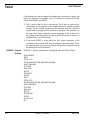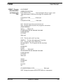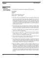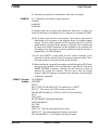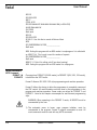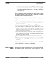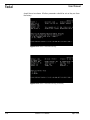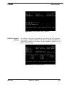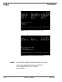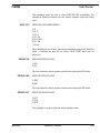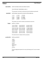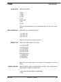
1
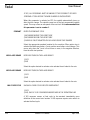
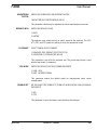
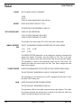
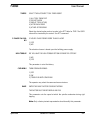
Fadal
User Manual
Section 21: Formats
From the SETP Command the control has the option to use either FORMAT 1 or
FORMAT 2.
Overview
Format 1
Format 1 is FADAL style programming and machine operation.
Format 1 has been uniquely designed to have the CNC control reset before
restarting machine operation. When the CNC control is in Format 1 the
programmer may program with the minimal of commands. This helps the user
for programming, setup, and operation. Some codes are unique for FORMAT 1
and FORMAT 2. Listed in this chapter are examples for each formats
programming style.
Format 2
Format 2 allows a 6M/ 10M /11M style programming and machine operation.
Format 2 follows the design to allow the programmer to completely command
the CNC control. All resets therefore must be done by the programmer in the
program and machine operation. Some codes are unique for FORMAT 2 and
FORMAT 1. Listed in this chapter are examples for each format’s programming
style.
Format 1
Programming
Notes on Format 1
Style Programming
1) Each line requires a sequence number and will be generated by the CNC
control. Sequence numbers use an N####.### word. Decimal points can be
used to input lines between existing line numbers. The sequence numbers
can be added when the program is typed at the computer, but the numbers
are added automatically when the program is transferred to the control with
the TA (tape input) command. So it is possible to type the program without
line numbers and have the control add the line numbers automatically. The
NU command is used to renumber the lines.
2) Decimals are required for all dimensions, feed rates, and angles.
EXAMPLE:
April 2003
X Y Z ###.#### (or ##.##### for higher precision)
F ####.##
A ####.###
B ####.###
Section 21: Formats
511
Fadal
User Manual
If the decimal point does not appear with dimensions, feed rates, or angles, the
control will add them. For example, if an X1 is entered it is accepted as X.0001
(See also DECIMALS and SIGNS).
3) The O word on the first line is not required. The O word is used only for
identification of the program in the program library for multiple program
storage. The first sixteen characters of the comment with the O word will
appear when the program library directory is displayed. This comment can
be longer than sixteen characters but the remainder of the comment will
only appear when the program is listed or printed (See also the section on
program library, the PR command).
4) If the word NOEDIT is used within the first sixteen characters of the
comment on the line with the O word, the program cannot be edited. This is
the same function as using the key lock on the pendant. Program can only
be deleted with the PR command.
FORMAT 1 Program
Example
EXAMPLE 1, without subroutines or subprogram calls with fixture offsets:
O# (COMMENT
M6 T1
(TOOL #1 ID
G0 G90 S##### M3 E## X###.#### Y###.####
H# M7 Z###.####
G4 P1000
Math work
M5 M9
G0 G90 80
Z0 G53
M6 T2
(TOOL #2 ID
G0 G90 S##### M3 E## X###.#### Y###.####
H# M7 Z###.####
G4 P1000
Math work
M5 M9
G0 G90 G80
Z0 G53
E0 X0 Y0 H0
M2
512
Section 21: Formats
April 2003
Fadal
FORMAT 1 Program
with Subroutines
and Subprogram
Calls
User Manual
O# (COMMENT
(SUBROUTINE SECTION
L100 (SUB #1 FOR _______ Each sub begins with an L word, a sub
Math worknumber (1-99), and a two digit zero repetition (00)
M17
L200 (SUB #2 FOR _______ ) Math work
M17
L300 (SUB #3 FOR _______ ) Math work
M17 This M17 marks the end of the last sub
M30 The M30 marks the end of the program’s sub section
(MAIN PROGRAM)
M6 T1(.........TOOL #1 ID
G0 G90 S##### M3 E## X###.#### Y###.####
H# M8 Z###.####
G4 P1000
Math work
L101 This line calls sub #1 one time
M98 P5 L1 This line calls subprogram 5 one time
L215 This line calls sub #2 fifteen times
G91 X##.#### L9 The L9 repeats this line nine times
M5 M9
G0 G90 G80
Z0 G53
M6 T2(..........TOOL #2 ID
G90 G0 S##### M3 E## X###.#### Y###.####
H# M8 Z###.####
G4 P1000
Math work
M5 M9
G0 G90 G80
Z0 G53
E0 X0 Y0
M2
O5 (SUBPROGRAM #5 FOR ______________ Math work
M99 Ending this program with an M99 makes it a subprogram
April 2003
Section 21: Formats
513
Fadal
Format 2
Programming
Notes on Format 2
Style Programming
User Manual
1) The safe block is mandatory at the beginning of the program.
O# (COMMENT
(COMMENT
Z0 G53
G0 G17 G40 G70 G80 G90 H0 E0 Z0
G28 X0 Y0 Z0
A0 B0 if needed
2) The G28, with the axis designated to move, will bring the machine to the
zero position established by the cold start command (CS) or to the zero
position established by the SETX, SETY, SETZ, or SETH commands and/or
fixture offsets, whichever was used last. The SET commands can be used
to establish a zero position at any desired location. The program does not
need to start from the machine home position. See also the section on
establishing home position.
3) Fixed subroutines such as bolt hole pattern subroutines or pocket cutting
routines from other machines cannot be used on this control. See the users
manual for information on using fixed subroutines from the CNC 88 control.
4) The SETP command allows certain changes to default codes, diameter or
radius input, and M7 M8 preferences.
5) When typing any variable (R0,R1 - R9) always type the positive or negative
symbol before the value, for example, R1+.5 R2+2.34 R3+5.7124 R46.765. See Section Six, Subroutines for proper usage.
6) The H word will only pick up the tool length offset. The D word must be
used to pick up the diameter or radius from the tool table.
7) Tool changes can be made from any XY position. The M6 code change will
move the head to the tool position and make the exchange. The T word and
the M6 can appear together, M6T# or T# M6, and usually do with this type
of tool changer; however they may appear on separate lines.
8) Each line requires a sequence number. Sequence numbers use an
N####.### word. Decimal points can be used to input lines between existing
line numbers. The sequence numbers can be added when the program is
typed at the computer, but the numbers are added automatically when the
program is transferred to the control with the TA (tape input) command. So
it is possible to type the program without line numbers and have the control
add the line numbers automatically. The NU command is used to renumber
the lines.
514
Section 21: Formats
April 2003
Fadal
User Manual
9) Decimals are required for all dimensions, feed rates, and angles.
EXAMPLE:
X Y Z ###.#### (or ##.##### for higher precision)
F ####.##
A ####.###
B ####.###
If decimals points do not appear with dimensions, feed rates, or angles, the
control will add them. For example if an X1 is entered it is accepted as X.0001.
10) The O word on the first line is not required. The O word is used only for
identification of the program in the program library for multiple program
storage. The first sixteen characters of the comment with the O word will
appear when the program library directory is displayed. This comment can
be longer than sixteen characters but the remainder of the comment will
only appear when the program is listed or printed (see also the section on
program library, the PR command).
11) If the word NOEDIT is used within the first sixteen characters of the
comment on the line with the O word, the program cannot be edited. This is
the same function as using the key lock on the pendant.
12) When transferring a program from another control through the RS232 port,
the original line numbers can be maintained by selecting #2 from the N
WORDS ORDERED: parameter. Selecting this will cause the control to
maintain the original line numbers. The first row is from the original
program. When the program is output from the machine, only the original
numbers are outputted.
FORMAT 2 Program
Example
April 2003
O# (COMMENT
(COMMENT
G53 Z0
G0 G17 G40 G70 G80 G90 H0 Z0 This safety line is a RESET
E0 X0 Y0 This moves to the SETH position or cold start
G54 X##.#### Y##.#### (or E1 X# Y# or G92 X# Y# are alternative
M6 T1
(TOOL #1 ID
G0 G90 S##### M3 X###.#### Y###.####
H# M8 Z###.#### D#
G4 P1000
Math work
M98 P4 L4 This calls subprogram #4 four times
M98 P3 L27 This calls subprogram #3 twenty seven times
G91 X##.#### G90 L9 The L9 repeats this line nine times
Section 21: Formats
515
Fadal
User Manual
M5 M9
G0 G90 H0 Z0
M6 T2
(TOOL #2 ID
G0 G90 S##### M3 X###.#### Y###.#### E## (or G54-G59)
H# M8 Z###.#### D#
G4 P1000
Math work
M5 M9
G0 G90 H0 Z0
E0 X0 Y0 Use this line to cancel all fixture offsets
M30
O3 (SUBPROGRAM #3 FOR ______________
Math work
M99 Ending this program with an M99 makes it a subprogram. It is called with
an M98 P3 L#. The L word is used for number of repeats
O4 (SUBPROGRAM #4 FOR ______________
Math work
M98 P3 L1 Sub #4 is calling sub #3 one time (nesting)
M99 Ending this program with an M99 makes it a subprogram
Default Parameters,
SETP Command
FORMAT 1 &
FORMAT 2
Changing from FORMAT 1 (FADAL mode), to FORMAT 2 (6M, 10M, 11M mode),
is done from the SETP mode.
Format 2 allows a 6M/ 10M /11M style programming and machine operation.
Format 2 follows the design to allow the programmer to completely command
the CNC control. All resets therefore must be done by the programmer in the
program and machine operation. Some codes are unique for FORMAT 2 and
FORMAT 1. Listed in this chapter are examples for each formats programming
style.
!
516
WARNING: When operating in the FORMAT 2 mode, All RESETS must be
commanded by the user.
1) The automatic move to home, upon program initiation, must be
commanded in the program. Format 2 requires commands to reset. All
reset commands must be used with any AUTO command.
Section 21: Formats
April 2003
Fadal
User Manual
a. In most cases it is required to use the SETCS then the HO command to
place the machine to the CS alignment position before typing SETP.
Verify that the alignment markers all line up. User may be instructed to
COLD START CNC.
The SETP command is generally used by the factory and by the set-up person
who installs the machine. It can also be used by the end user to establish
programming, baud rate, and output preferences.
Note: The factory set parameters can be found on the inside of the pendant
door.
1) Move the machine to the cold start position if changes will be made to the
parameter settings. The machine Cold Start must be accomplished when
parameters are changed.
2) From the command mode type SETP then press the ENTER button.
3) The menu prompt at the bottom of the screen defines the use of the
keyboard to move the cursor to the parameter to change. When the
parameter to change has the cursor to its left, the parameter choices will de
displayed at the bottom of the screen.
4) Select the parameter choice by pressing the number corresponding to the
choice and press the ENTER button. The parameter will display the change
and the cursor will move to the right.
5) Press the MANUAL button to exit and save the parameter setting mode.
Note: If changes are made to any of the parameters, in most cases the CNC
control will require a COLD START. Follow the power on procedure (see
POWER ON).
The following pages have the recommended format settings for the FADAL
FORMAT 1 and FORMAT 2 6MB,10M,11M compatibility.
FORMAT 1 Parameter
Settings
April 2003
The following is the screen’s representation upon entering the SETP command.
The parameters FORMAT, DEFAULTS, IMM> FIXED CYCLE and CRC MODE
Section 21: Formats
517
Fadal
User Manual
should be set as shown. All other parameters should be set as they are from
the factory.
Figure 21-1 Format 1 Parameter Settings
Figure 21-2 Format 1 Parameter Settings (Continued)
518
Section 21: Formats
April 2003
Fadal
User Manual
Figure 21-3 Format 1 Parameter Settings (Continued)
FORMAT 2 Parameter
Settings
The following is the screen representation upon entering the SETP command.
The parameters FORMAT, DEFAULTS, CRC MODE, N-WORDS ORDERED and
TOOL TABLE should be set as shown. All other parameters should be set as
they are from the factory.
Figure 21-4 Format 2 Parameter Settings
April 2003
Section 21: Formats
519
Fadal
User Manual
Figure 21-5 Format 2 Parameter Settings (Continued)
Figure 21-6 Format 2 Parameter Settings (Continued)
FORMAT
THERE ARE TWO PROGRAM OPERATION FORMATS AVAILABLE
DO YOU WANT MAXIMUM 6MB/10M/11M CAPABILITY?
1) NO, ORIGINAL FADAL STYLE - FORMAT 1
2) YES, FORMAT 2
520
Section 21: Formats
April 2003
Fadal
User Manual
This parameter allows the user to select 6MB/10M/11M compatibility. The
operational difference between the two formats depends upon the coding
used.
AXES: X,Y,Z
ENTER THE AXIS CONFIGURATION
1) A
2) A, B
3) X,Y,Z
4) X,Y,Z,A
5) X,Y,Z,A,B
6) X,Y,Z,B
7) C only
When selecting the A or B axes, the machine should be powered off. When the
power is returned the axes will be active. COLD START must then be
performed.
DEFAULT: G0
ENTER THE DEFAULT VALUE
1) G0
2) G1
The code selected is active at power on and when entering the MDI mode.
DEFAULT: G90
ENTER THE DEFAULT VALUE
1) G90
2) G91
The code selected is active at power on and when entering the MDI mode.
DEFAULT: G17
ENTER THE DEFAULT VALUE
1) G17
2) G18
3) G19
This parameter is used to select the default machine plane.
April 2003
Section 21: Formats
521
Fadal
User Manual
RPM FACTOR
ENTER THE SPINDLE RPM ADJUSTMENT FACTOR
THE FACTOR MUST BE BETWEEN 0 AND 31
This parameter should only be adjusted by trained maintenance personnel.
BAUD RATE
ENTER DEFAULT BAUD RATE (THE RATE AFTER POWER-ON)
1) 110
2) 150
3) 300
4) 600
5) 1200
6) 2400
7) 4800
8) 9600
9) 19200
10) 38400
11) 57600
12) 115200
The operator may select the desired communications baud rate.
TRAVEL
ENTER X,Y,Z TRAVEL
1) X22 Y16 Z20
2) X20 Y12 Z20
3) X20 Y13.5 Z20
4) X22 Y13.5 Z20
5) X22 Y13 Z20
6) X20 Y13 Z20
7) X40 Y20 Z20
8) X40 Y20 Z28
9) X60 Y30 Z30
10) X22 Y16 Z28
11) X20 Y16 Z20
12) X20 Y16 Z28
13) X30 Y16 Z20
14) X30 Y16 Z28
15) X50 Y20 Z20
16) X50 Y20 Z28
17) X80 Y30 Z30
18) X30 Y20 Z24
19) X30 Y20 Z32
20) X20 Y20 Z24
21) X20 Y20 Z32
The machine travel is selected with this parameter.
A-AXIS RATIO
ENTER A-AXIS RATIO
1) 90:1
2) 180:1
3) 360:1
4) 120:1
5) 72:1
6) COOLANT
7) 60:1
8) 144:1
Select the appropriate option for the rotary table being used. See servo coolant
option.
522
Section 21: Formats
April 2003
Fadal
B-AXIS RATIO
User Manual
ENTER B-AXIS RATIO
1) 90:1
2) 180:1
3) 360:1
4) 120:1
5) 72:1
6) COOLANT
7) 60:1
8) 144:1
Select the appropriate option for the rotary table being used. See servo coolant
option.
TOOL CHANGER CAP
ENTER THE TOOL CHANGER CAPACITY
1) 16 TOOL ATC
2) 21 TOOL ATC
3) 30 TOOL ATC
Select the appropriate tool changer capacity.
SPINDLE TYPE
ENTER THE SPINDLE DRIVE TYPE & RPM
1) 10,000 HI/LOW
2) 10,000 3 STEP
3) 15,000 DIRECT
4) 5,000 HI/LOW
5) 6,500 HI/LOW
6) 3750 WYE/DEL.
7) 7500 WYE/DEL.
8) 5000 DIRECT
9) 15K WYE/DEL.
Select the correct spindle type for the machine. This parameter is set at the
factory.
SPINDLE AFTER M6
SHOULD SPINDLE COME ON AUTOMATICALLY AFTER A TOOL CHANGE WHEN
THE M6 HAD TO TURN THE SPINDLE OFF?
1) NO (FADAL RECOMMENDS THIS RESPONSE)
2) YES
April 2003
Section 21: Formats
523
Fadal
User Manual
IF YES, ALL PERSONNEL MUST BE AWARE OF THE POSSIBILITY OF OVER
SPEEDING A TOOL BEFORE THE NEW S-WORD IS ENCOUNTERED
When this parameter is selected as YES, the spindle automatically turns on
after the tool change. The spindle comes on at the last programmed spindle
speed. This may cause an overspeed of the next tool. It is recommended that
this parameter is set to number 1.
PENDANT
ENTER THE PENDANT STYLE
1) KEYBOARD BESIDE THE VIDEO TUBE
2) KEYBOARD BELOW THE VIDEO TUBE
3) SAME AS 2 BUT MOUNTED ON FULL-ENCLOSURE CHIP GUARDS
Select the appropriate pendant location for the machine. When option two is
selected the table may make a Y axis positive move before a tool change. This
occurs only when the Y axis is five inches or more, in the negative direction,
from the cold start position.
M60/A-AXIS BRAKE
DOES M60 TURN ON THE A-AXIS BRAKE?
1) YES
2) NO
Select the option desired to activate or de-activate the air brake for the axis.
M62/B-AXIS BRAKE
DOES M62 TURN ON THE B-AXIS BRAKE?
1) YES
2) NO
Select the option desired to activate or de-activate the air brake for the axis.
IMM. FIXED CYCLE
SHOULD A FIXED CYCLE EXECUTE IMMEDIATELY?
1) YES
2) NO, ONLY IF X OR Y DIMENSION WORDS ARE IN THE DEFINITION LINE
A YES response causes a fixed cycle to be executed immediately upon
definition at the current axis location. A NO response requires axis motion to
activate the fixed cycle.
524
Section 21: Formats
April 2003
Fadal
ORIENTATION
FACTOR
User Manual
ENTER THE SPINDLE RPM ADJUSTMENT FACTOR
THE FACTOR MUST BE BETWEEN 0 AND 31
This parameter should only be adjusted by trained maintenance personnel.
DEFAULT: INCH
ENTER THE DEFAULT VALUE
1) INCH
2) METRIC
The operator must select the inch or metric mode for the machine. The G70,
G71, G20, and G21 check this setting to verify the operational mode.
PU FORMAT
SELECT PUNCH OUTPUT FORMAT
1) PUNCHED TAPE FORMAT (TELETYPE STYLE)
2) COMPUTER FILE FORMAT (NO NULLS)
This parameter is set to file for computer use. The punch tape format is used
when a tape reader is employed.
CRC MODE
ENTER THE DEFAULT OUTSIDE CORNER MOVEMENT
1) M96 - ROLL
2) M97 - INTERSECTIONAL
This parameter selects the default mode for intersectional cutter radius
compensation.
SPINDLE OFF
DO YOU WANT THE SPINDLE TO TURN OFF WHEN EXITING JOG OR MANUAL
DATA INPUT?
1) NO
2) YES
This parameter is set at the factory and should not be changed.
April 2003
Section 21: Formats
525
Fadal
User Manual
PALLET
DO YOU HAVE A PALLET CHANGER?
1) NO
2) YES
Select the option appropriate for the machine.
ASPECT
ENTER THE ASPECT RATIO OF Y TO X
THE RATIO MUST BE BETWEEN 25 AND 150
M7-FLOOD M8-MIST
ENTER M7, M8 PREFERENCE
1) M7 IS FLOOD COOLANT, M8 IS MIST
2) M8 IS FLOOD COOLANT, M7 IS MIST
The operator may select either M7 or M8 as the flood coolant code.
BINARY BUFFERS:
255
SELECT THE NUMBER OF BINARY BUFFERS FOR CNC LOOK-AHEAD.
1) 15
2) 30
3) 50 5) 255
4) 100
The BINARY BUFFERS parameter can be changed to increase or decrease the
control look ahead. The factory sets the buffers at 255. This is the most
effective for programs with many small moves that must be executed rapidly.
This parameter is used to more efficiently utilize the Run Time Menu. The
smaller the buffers the more quickly the Run Time Menu changes will take
effect in the program.
TURRET FACTOR
ENTER THE ENGAGEMENT FACTOR FOR THE TOOL TURRET GENEVA GEAR
THE FACTOR MUST BE BETWEEN 1 AND 50 (1 FOR SERVO TURRET)
This parameter is set at the factory. For VMCs equipped with the Servo Turret,
this factor MUST always be 1.
GAIN
ENTER THE GAIN FACTOR FOR RIGID TAPPING
THE FACTOR MUST BE BETWEEN 0 AND 255
This parameter effects the spindle response during rigid tapping. The higher
the number the faster the spindle turns in relation to the feed rate. When the
speed is too fast the thread may be too loose.
526
Section 21: Formats
April 2003
Fadal
User Manual
TIMERS
SELECT THE AUTOMATIC TOOL TIMER MODE?
1) ALL TOOL TIMING OFF
2) DO NOT CHECK
3) END OF TOOL (AT M6)
4) AFTER EACH MOVE
5) AT END OF PROGRAM
Select the desired option and set a value in the DTT table for TIME. The USED
value will be inserted by the control. See DTT command.
3 PHASE 5% LOW:
NO
IS YOUR 3 PHASE POWER MORE THAN 5% LOW?
1) YES
2) NO
The selection chosen is based upon the building power supply.
HIGH TORQUE
DO YOU HAVE THE HIGH TORQUE OPTION OR RIGID TAP OPTION?
1) NO
2) YES
This parameter is set at the factory.
CMD MENU
TURN COMMAND MENUS:
1) OFF
2) ON
3) TOGGLE ON WITH SPACE BAR
The operator may select the command menu structure.
RAMP
ENTER THE RAMP FACTOR FOR RIGID TAPPING
THE FACTOR MUST BE BETWEEN 0 AND 255
This parameter sets the speed at which the spindle accelerates during rigid
tapping.
Note: Only a factory trained representative should modify this parameter.
April 2003
Section 21: Formats
527
Fadal
User Manual
OVERLOAD
ENTER THE MOTOR OVERLOAD FACTOR (2 IS STANDARD)
THE FACTOR MUST BE BETWEEN 1 AND 8
SCREW
SELECT THE SCREW PITCH TYPE?
1) INCH PITCH
2) 8/10MILLIMETER PITCH
IPM
SELECT THE MAX RAPID FEED RATE?
1) 400 IPM
2) 500 IPM
3) 700 IPM
XYZ RAMP
4) 800 IPM
5) 900 IPM
ENTER THE X, Y, & Z RAMP LENGTH FACTOR (160 IS STANDARD)
THE FACTOR MUST BE BETWEEN 50 AND 200
This parameter sets the speed at which the axes accelerate and decelerate
during travel.
Z TAP GAIN
SELECT THE Z GAIN DURING RIGID TAPPING?
1) NORMAL
2) MEDIUM
3) HIGH
Only a factory trained representative should modify this parameter.
VECTOR
DO YOU HAVE VECTOR DRIVE (10 RPM MIN)?
1) YES
2) NO
AXIS DISPLAY
DISPLAY THE AXIS FOLLOW ERROR OR LOAD?
1) LOAD PERCENTAGE
2) FOLLOWING ERROR
This option is used to select what the axis display will show on the position
display while auto running a program.
528
Section 21: Formats
April 2003
Fadal
User Manual
A-PALLET
WHICH ROTARY AXIS IS INSTALLED ON THIS PALLET?
1) NOT APPLICABLE
2) A-AXIS
3) B-AXIS
4) A-AXIS & B-AXIS
Select the appropriate option for the rotary axis being used.
B-PALLET
WHICH ROTARY AXIS IS INSTALLED ON THIS PALLET?
1) NOT APPLICABLE
2) A-AXIS
3) B-AXIS
4) A-AXIS & B-AXIS
Select the appropriate option for the rotary axis being used.
AUTO BRAKE
AUTOMATICALLY APPLY THE A OR B BRAKE DURING IDLE TIME?
1) YES
2) NO
Select the option desired to activate or de-activate the air brake for the axes.
5th AXIS
PROGRAMMABLE
HEAD
DO YOU HAVE THE 5TH AXIS PROGRAMMABLE HEAD ATTACHMENT?
1) NO
2) YES
Answer YES if a 4th or 5th axis rotary head attachment is installed in the
spindle.
G0 DETAIL
ENTER THE DETAIL DESIRED FOR G0 MOVES
BETWEEN 2 TO 250 TENTHS (251=OFF)
Enter a value between 2 and 250 to set the maximum distance to allow before
the control will continue with the next motion block. Smaller values may have
the tendency to cause the machine to wait at the end of G0/G5 moves. The
value of 251 can be set to turn off the feature. This parameter should be set to
any preference, as it will not affect contouring motion.
April 2003
Section 21: Formats
529
Fadal
User Manual
AIR VALVE
FEEDBACK
DO YOU HAVE AIR VALVE FEEDBACK?
1) NO
2) YES
Answer NO only for machines built previous to having feedback on the
drawbar.
Parameters
Applicable to
FORMAT 2 Only
N-WORDS ORDERED
ENTER THE N-WORD SEQUENCE CONFIGURATION
1) THE N-WORDS ARE IN ASCENDING NUMERICAL ORDER OR
THE PROGRAM WILL BE RENUMBERED AFTER INPUT.
2) THE N-WORDS ARE NOT IN ORDER.
The CNC 88 requires each block of NC code to have sequence numbers in
numerical order. Since the 6MB/10M/11M controls do not require block
numbers in numerical order, select option number 2. Upon tape input the CNC
will add sequence numbers for reference. Otherwise after tape input the
program must be renumbered if the sequence numbers are not in numerical
order.
TOOL TABLE
WILL THE TOOL COMPENSATION TABLE HAVE THE RADIUS OR DIAMETER?
1) DIAMETER
2) RADIUS
The cutter offset specification in the tool compensation table may be defined
as a diameter or radius.
The SETP mode is exited by pressing the MANUAL key. If new values were
selected, the CNC may require that you perform the Cold Start procedure (see
CS command).
530
Section 21: Formats
April 2003