1
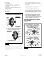
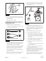
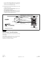
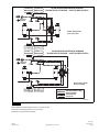
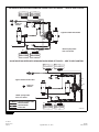
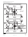
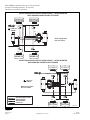
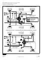
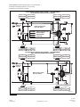
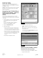
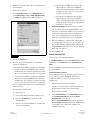
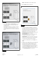
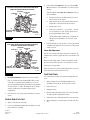
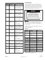
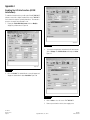
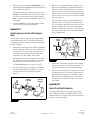
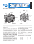
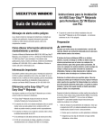
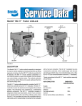
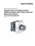
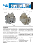
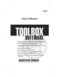
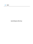
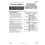
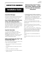
TP-20214
Revised 11-15
Installation Guide
Hazard Alert Messages
Read and observe all Warning and Caution hazard alert messages in
this publication. They provide information that can help prevent
serious personal injury, damage to components, or both.
How to Obtain Additional Maintenance,
Service and Product Information
Refer to Maintenance Manual MM-0180, Enhanced Easy-Stop™
Trailer ABS with PLC; Maintenance Manual 33, Easy-Stop™ Trailer
ABS; and Parts Book PB-96133, Enhanced Easy-Stop™ with PLC
and Easy-Stop™ Trailer ABS. To obtain these publications, call the
Meritor OnTrac™ Customer Call Center at 866-OnTrac1
(668-7221), or visit our website at meritorwabco.com.
Important Information
Use only genuine Meritor WABCO components. Other
manufacturers’ parts are not designed for use with a Meritor
WABCO ABS system and may not function correctly.
Meritor WABCO recommends that a control line filter, part number
432-500-005-0, be installed on the air system’s control line,
upstream of the ABS ECU/valve assembly.
Differences Between Easy-Stop™ and
Enhanced Easy-Stop™
There are some changes to Enhanced Easy-Stop™ that you need to
be aware of before you begin the installation.
앫 Enhanced Easy-Stop™ includes Power Line Communication
(PLC) function.
앫 The ECU/dual modulator valve assembly must be mounted as
one unit.
앫 The LED on top of the ECU has been eliminated.
앫 The blink code tool LED does not operate simultaneously with the
ABS lamp on the trailer.
Enhanced Easy-Stop™ Trailer
ABS 2S/2M, 4S/2M and 4S/3M
Premium with PLC Installation
Instructions
Revised
1TP-20214
Technical
11-15
Bulletin
앫 For Enhanced Easy-Stop™ 4S/3M lift axle installations, you
must use TOOLBOX™ Software, version 4.6 or higher, to enable
the lift axle function. It is not automatically enabled. Refer to
Enabling the Lift Axle Function (4S/3M Installations) in the
Appendix for instructions. For 4S/2M lift axle installations, the lift
axle function is automatically enabled.
The valve portion of the ECU/dual modulator valve assembly
contains two separate modulator valves that share common control
and exhaust ports.
Each valve has three delivery ports. Therefore, the mounting
orientation — whether the valve is facing the front or the rear of the
trailer — determines sensor hookup.
If this assembly is mounted facing forward — toward the front of
the trailer — the YE sensor connections go to the curbside and the
BU sensor connections go to the roadside. If this assembly is
mounted facing the rear, the YE sensor connections go to the
roadside, and the BU sensor connections go to the curbside.
Figure 1.
All premium systems use the same ECU/dual modulator valve
assembly.
The ECU/dual modulator assembly cannot be used as a 2S/1M
system.
Figure 1
ECU/DUAL MODULATOR VALVE MOUNTED WITH
SENSORS FACING FRONT OF TRAILER
CURBSIDE
YE2
CURBSIDE
YE1
ROADSIDE
BU1
ROADSIDE
BU2
Park the vehicle on a level surface. Block the wheels to
prevent the vehicle from moving. Support the vehicle with
safety stands. Do not work under a vehicle supported only by
jacks. Jacks can slip and fall over. Serious personal injury and
damage to components can result.
1.
SUPPLY
PORT
CONTROL
PORT
앫 Look for crushed or bent connectors.
PLUG ALL
UNUSED
PORTS
DELIVERY
CURBSIDE
EXHAUST
PORT
ROADSIDE
YE1
ROADSIDE
YE2
SUPPLY
PORT
CURBSIDE
BU1
CURBSIDE
BU2
CONTROL
PORT
PLUG ALL
UNUSED
PORTS
앫 Do not install a damaged ECU/dual modulator valve
assembly. Notify your supervisor, or contact Meritor WABCO
if there is any apparent damage.
2.
Have the following installation material available.
* ECU/dual modulator valve assembly
* ABS relay valve and relay valve extension cable with bayonet
connector (3M systems)
* Power cable or power/diagnostic cable
* Sensor extension cables (two pieces for 2S systems, four
pieces for 4S systems)
* Sensors (two or four) for non-ABS prepped axles
* ABS Indicator Label (TP-95172)
DELIVERY
ROADSIDE
EXHAUST
PORT
DELIVERY
CURBSIDE
4003566a
Figure 1
5/8-inch O.D. nylon tubing for supply (frame mount)
Pipe plug (3/4-inch NPTF)
Schedule 80 hex pipe nipple (3/4-inch NPTF) for air tank
mounts or two Grade 8 bolts (3/8-inch) and prevailing torque
nuts for frame mounts
Preparation
SAE-standard, DOT-approved thread sealant
WARNING
To prevent serious eye injury, always wear safe eye protection
when you perform vehicle maintenance or service.
The Anti-lock Braking System (ABS) is an electrical system.
When you work on the ABS, take the same precautions that
you must take with any electrical system to avoid serious
personal injury. As with any electrical system, the danger of
electrical shock or sparks exists that can ignite flammable
substances. You must always disconnect the battery ground
cable before working on the electrical system.
TP-20214
Revised 11-15
Page 2
앫 Verify that the retainer clips have not been bent or
otherwise damaged.
DELIVERY
ROADSIDE
ECU/DUAL MODULATOR VALVE MOUNTED WITH
SENSORS FACING REAR OF TRAILER
Before beginning the installation procedure, inspect the ECU/
dual modulator valve assembly for damage that may have
occurred during shipping or storage.
To ensure correct lamp operation, use an incandescent-type
DOT-approved lamp, or an LED with integral load resistor.
* Meritor WABCO components
End of line testing must be done after all installations. Meritor
WABCO recommends using TOOLBOX™ Software to perform
this testing. If you do not have TOOLBOX™ Software, this
bulletin also includes instructions for testing without the
software.
Copyright Meritor, Inc., 2015
(16579)
Printed in USA
Installation
1.
I. Install the ECU/dual modulator valve
assembly.
Meritor WABCO does not recommend the use of a vise when
installing the hex nipple. Use of a vise may cause
overclamping. Overclamping may damage the internal
components of the ECU/dual modulator valve assembly.
The assembly may be mounted on the air tank or on the cross
member of the vehicle.
Tank-Mounted
2.
Use a 3/4-inch NPTF pipe plug to plug the unused supply port.
Apply SAE-standard, DOT-approved Teflon tape or paste-type
thread sealant to all pipe threads beyond the first two threads.
Pipes with pre-applied thread sealant may also be used.
3.
Rotate and tighten the ECU/dual modulator valve assembly
until the exhaust port faces DOWN and the connection is
secure. Use a torque wrench or ratchet with an extension at the
3/4-inch pipe plug installed on the front supply port.
Refer to Figure 2.
Figure 2
ECU/DUAL MODULATOR VALVE MOUNTED WITH
SENSORS FACING FRONT OF TRAILER
(TANK-MOUNTED)
Use a 3/4-inch NPTF Schedule 80 hex nipple to attach the
ECU/dual modulator valve assembly to a reinforced air tank. Do
not overtighten.
CURBSIDE
YE2
Mounted to Cross Member of Vehicle (Mounting
Bracket Not Supplied)
CURBSIDE
YE1
Refer to Figure 3.
ROADSIDE
BU1
Figure 3
ECU/DUAL MODULATOR VALVE MOUNTED
TO A CROSS MEMBER OF THE VEHICLE WITH
SENSORS FACING FRONT OF TRAILER
ROADSIDE
BU2
Exhaust port
must face DOWN.
ECU/DUAL MODULATOR VALVE MOUNTED WITH
SENSORS FACING REAR OF TRAILER
PLUG ALL
UNUSED PORTS
ROADSIDE
BU2
CURBSIDE
BU2
CURBSIDE
BU1
ROADSIDE
YE1
ROADSIDE
YE2
PLUG UNUSED
PORT
Exhaust port
must face DOWN.
ROADSIDE
BU1
CURBSIDE
CURBSIDE
YE2
YE1
FRONT OF
TRAILER
ECU/DUAL MODULATOR VALVE MOUNTED WITH
SENSORS FACING REAR OF TRAILER
Exhaust port
must face DOWN.
ROADSIDE
YE2
PLUG ALL
UNUSED PORTS
4003548a
ROADSIDE
YE1
Figure 2
CURBSIDE
BU1
WARNING
You must use a Schedule 80 hex nipple (3/4-inch NPTF) to
mount the ECU/dual modulator valve assembly securely to the
air tank to avoid possible serious personal injury and damage
to the component.
(16579)
Printed in USA
CURBSIDE
BU2
FRONT OF
TRAILER
4005403b
Figure 3
Copyright Meritor, Inc., 2015
TP-20214
Revised 11-15
Page 3
When mounting the ECU/dual modulator valve assembly to the
trailer cross member, refer to SAE specification J447, Prevention of
Corrosion of Motor Vehicle Body and Chassis Components. Follow
all recommendations and procedures. Your supervisor should have a
copy of this specification.
1.
Use a 3/4-inch NPTF pipe plug to plug the unused supply port.
Apply SAE-standard, DOT-approved Teflon tape or paste-type
thread sealant to all pipe threads beyond the first two threads.
Pipes with pre-applied thread sealant may also be used.
3.
Rotate and tighten the relay valve assembly until the exhaust
port faces down and the connection is secure. Use a torque
wrench or ratchet with an extension at the 3/4-inch pipe plug
installed on the front supply port. Figure 4.
Install a 3/4-inch NPTF fitting in the supply port. Use a 3/4-inch
NPTF pipe plug to plug the unused supply port (Port 1).
Apply SAE-standard, DOT-approved Teflon tape or paste-type
thread sealant to all pipe plugs beyond the first two threads.
Pipes with pre-applied thread sealant may also be used.
2.
2.
Figure 4
PLUG
UNUSED
PORTS
Locate a position for mounting the assembly to the vehicle
cross member midway between the side rails, close to the
brake chambers the valve serves.
Exhaust
port must
face DOWN.
앫 Drill two 3/8-inch mounting holes. The distance between
the two holes (O.D.) must be 6.06-inches (154 mm) and
mount directly to the cross member.
CONTROL
PORT 4
SUPPLY
PORT 1
OR
ABS EXTERNAL MODULATOR VALVE
앫 Build a mounting bracket with two 3/8-inch mounting holes
spaced 6.06-inches (154 mm O.D.) apart.
CAUTION
Place a thin barrier of plastic, mylar or similar material
between the bracket and mounting surface. The barrier is
necessary to inhibit corrosion, which can occur from contact
between dissimilar metals. Galvanic corrosion can result in
damage to the ECU/modulator assembly.
3.
Place a thin barrier made of plastic, mylar or similar material
between the bracket and mounting surface to inhibit corrosion.
4.
Use two 3/8-inch Grade 8 bolts with prevailing torque nuts to
attach the assembly. Tighten the bolts to 18 lb-ft (24 N폷m). @
1002073d
Figure 4
Mounted to Cross Member of Vehicle (Mounting
Bracket Not Supplied)
When mounting the relay valve assembly to the trailer cross
member, refer to SAE specification J447, Prevention of Corrosion of
Motor Vehicle Body and Chassis Components. Follow all
recommendations and procedures. Your supervisor should have a
copy of this specification.
1.
앫 Apply SAE-standard, DOT-approved Teflon tape or
paste-type thread sealant to all pipe plugs beyond the first
two threads. Pipes with pre-applied thread sealant may also
be used.
II. Attach the ABS external relay valve
(4S/3M systems only).
Tank-Mounted
2.
WARNING
You must use a Schedule 80 hex nipple (3/4-inch NPTF) to
mount the ECU/dual modulator valve assembly securely to the
air tank to avoid possible serious personal injury and damage
to the component.
1.
Use a 3/4-inch NPTF Schedule 80 hex nipple to attach the
relay valve assembly to a reinforced air tank. Do not
overtighten.
Meritor WABCO does not recommend the use of a vise when
installing the hex nipple. Use of a vise may cause
overclamping. Overclamping may damage the internal
components of the ECU/dual modulator valve assembly.
TP-20214
Revised 11-15
Page 4
Install a 3/4-inch NPTF fitting in the supply port. Use a 3/4-inch
NPTF pipe plug to plug the unused supply port (Port 1).
Install the valve with two locknuts and washers as required.
Tighten the hex nuts to 18 lb-ft (24 N폷m). @
III. Connect the air lines.
Before connecting the air lines, plumb the spring brake relay or
emergency brake relay into the system as usual.
앫 If you are mounting on a bracket, connect the air supply line from
the supply tank to the supply Port 1. Plug the unused port.
앫 Use 5/8-inch O.D. min. nylon tubing or heavy-walled Schedule
80 pipe nipple (3/4-inch NPTF) if you are mounting directly to the
supply tank.
Copyright Meritor, Inc., 2015
(16579)
Printed in USA
1.
2.
Connect the air delivery lines to the ECU/dual modulator valve
assembly Port 2. For 4S/3M installations, connect the air
delivery lines to Port 2 on the external relay valve (3/8-inch
NPTF).
3.
Connect the brake service (control) line to the ECU/dual
modulator valve assembly Port 4 (1/4-inch NPTF).
4.
For 4S/3M installations, perform the following procedures.
Connect the air delivery lines to the appropriate brake
chambers (3/8-inch NPT). Figure 5 and Figure 6.
앫 The valve portion of the ECU/dual modulator valve assembly
contains two separate valves: one dedicated to roadside
wheel ends, the other dedicated to curbside wheel ends.
Each valve has three delivery ports.
앫 The external relay valve designated RED (RD) is an axle
control valve. It controls brake chambers on one or two
axles. It is important that delivery lines from Port 2 are
plumbed as shown. Refer to Figure 13 through Figure 19.
Figure 5
TYPICAL 2M INSTALLATION — VALVE MOUNTED
WITH SENSORS FACING FRONT OF TRAILER
5.
A.
Connect the brake service (control) line to the ECU/dual
modulator valve assembly Port 4 (1/4-inch NPTF) and
ABS external relay valve control Port 4 (3/8-inch NPTF).
B.
Use an ABS relay valve connection cable to connect the
ECU/dual modulator valve assembly with the ABS external
relay valve.
Plug any unused delivery ports.
IV. Install the sensor extension cables
(ABS-prepped axles).
Instructions for installing sensors on non-ABS-prepped axles are
included in the Appendix.
Meritor WABCO recommends placing sensors on the axle that will
provide the most braking performance. The suspension
manufacturer can provide this information.
1.
Visually inspect the tooth wheel and sensor to ensure no
damage occurred during shipping. Perform any necessary
repairs.
2.
Connect the sensors and cables on the prepped axles to the
sensor extension cables. Figure 7.
Ensure that each connection is secure.
SERVICE/CONTROL LINES
SERVICE BRAKE
SUPPLY AIR
SPRING BRAKE AIR
Figure 7
4003550a
Figure 5
SENSOR
EXTENSION
CABLE
Figure 6
TYPICAL 2M INSTALLATION — VALVE MOUNTED
WITH SENSORS FACING REAR OF TRAILER
SENSOR
AND CABLE
4003567b
Figure 7
3.
SERVICE/CONTROL LINES
SERVICE BRAKE
SUPPLY AIR
SPRING BRAKE AIR
Route the sensor cable along the back side of the trailer axle to
the ECU/dual modulator valve assembly. Route the cable with
the brake hose.
4003551a
Figure 6
(16579)
Printed in USA
Copyright Meritor, Inc., 2015
TP-20214
Revised 11-15
Page 5
Do not overtighten the tie wraps on a cable. Overtightening can
damage the cable. Do not tie wrap the molded sensor plug.
The sensor extension cable must follow the brake hose to the
ECU/dual modulator valve assembly to allow for axle jounce
and rebound.
4.
Secure the cables every eight inches (203 mm) with tie wraps
or cable clips.
5.
Push the sensor retainer clip on the ECU/dual modulator valve
assembly UP.
6.
Remove the protective caps from YE2 and YE1 sensor
connectors.
7.
— Connect roadside sensor at YE1.
앫 4S/2M*
— Connect curbside front sensor at BU1.
— Connect curbside rear sensor at BU2.
— Connect roadside front sensor at YE1.
— Connect roadside rear sensor at YE2.
앫 4S/3M*— Sensor locations vary by type of installation.
Refer to the diagrams for specific sensor locations.
For Enhanced Easy-Stop™ 4S/3M lift axle
installations, you must use TOOLBOX™ Software, version
4.6 or higher, to enable the lift axle function. It is not
automatically enabled. Refer to Enabling the Lift Axle
Function (4S/3M Installations) in the Appendix for
instructions.
Plug the sensor extension cables into the ECU/dual modulator
valve assembly. To secure the connection, push the sensor
retainer clip DOWN. Retainer clips must fit in the groove of the
sensor connectors to ensure correct connection.
ECU/Dual Modulator Valve Assembly Mounted with
Sensors Facing Front of Trailer
— Connect curbside sensor at BU1.
— Connect curbside sensor at BU2.
앫 2S/2M
— Connect roadside sensor at YE1.
— Connect curbside sensor at YE1.
— Connect roadside sensor at YE2.
— Connect roadside sensor at BU1.
* If the lift axle is sensed in 4S/2M and 4S/3M
installations: Sensors YE2 and BU2 must always be used on
the lift axle to avoid an unwanted ABS indicator lamp
illumination.
앫 4S/2M*
— Connect curbside front sensor at YE1.
— Connect curbside rear sensor at YE2.
8.
— Connect roadside front sensor at BU1.
— Connect roadside rear sensor at BU2.
앫 4S/3M*— Sensor locations vary by type of installation.
Refer to the diagrams on the following pages for specific
sensor locations.
Create a strain relief to protect the sensor extension connector
terminals. Without this strain relief, normal trailer jounce and
vibration will cause the terminals to spread and loosen. Use a
tie wrap or clip to secure the cable to the brake air delivery
hose as close to the fitting as possible. Figure 8.
Figure 8
For Enhanced Easy-Stop™ 4S/3M lift axle
installations, you must use TOOLBOX™ Software, version
4.6 or higher, to enable the lift axle function. It is not
automatically enabled. Refer to Enabling the Lift Axle
Function (4S/3M Installations) in the Appendix for
instructions.
— Connect curbside sensor at YE1.
— Connect curbside sensor at YE2.
— Connect roadside sensor at BU1.
4005457b
— Connect roadside sensor at BU2.
ECU/Dual Modulator Valve Assembly Mounted with
Sensors Facing Rear of Trailer
Figure 8
9.
Bundle any excess cable in a “Z”-shaped loop. Figure 9.
앫 2S/2M
— Connect curbside sensor at BU1.
TP-20214
Revised 11-15
Page 6
Copyright Meritor, Inc., 2015
(16579)
Printed in USA
4.
Figure 9
BUNDLE
EXCESS
CABLE
Push the hinged power/diagnostic connector retainer clip UP
and remove the protective cap from the ECU/dual modulator
valve assembly. Figure 11.
Figure 11
CAP
KEYED CABLE
CONNECTOR
4003553a
Figure 9
10. Secure excess cable in the sub-frame of the vehicle or along
the air hoses as appropriate. Excess cable should not exceed
two feet (0.61 meter).
MATING
TRAILER
HARNESS
CONNECTOR
Various cable lengths are available.
4003569a
V. Install the power and lamp or power and
lamp/diagnostic cable.
1.
Identify the type of cable to be installed. Figure 10.
Figure 11
5.
Plug the power 8-pin connector on the power or power/
diagnostic cable into the ECU/dual modulator valve assembly.
6.
Pull the hinged power/diagnostic connector retainer clip on the
ECU/dual modulator valve assembly DOWN to secure the
connection.
7.
If you are installing the power cable only, go to Step 9.
8.
If you are installing the power/diagnostic “Y” cable:
앫 ABS trailer industry-standard pigtail connector power cable
앫 Blunt-cut power cable (not shown)
Figure 10
POWER CABLE
POWER/DIAGNOSTIC CABLE
A.
Install the diagnostic cable bracket so that the diagnostic
plug is accessible. The normal location is on the right
front corner of the sub-frame, but will vary depending on
the type of trailer.
B.
Route the diagnostic cable from the ECU/dual modulator
valve assembly to the diagnostic cable bracket.
C.
Correctly secure the cable in the sub-frame to prevent
cable damage.
4003568a
Figure 10
2.
For industry-standard pigtail connector power cables, route the
cable from the harness connector to the ECU/dual modulator
valve assembly and secure it to prevent damage.
For blunt-cut power cables, route the cable from the ECU/dual
modulator valve assembly to a junction box which interfaces
with the seven-way connector at the front of the trailer.
Leave enough slack in the cable to compensate for flexing of
the trailer and sub-frame.
3.
Bundle any excess cable in a loop (bow tie) and secure it in the
sub-frame of the trailer body to prevent cable damage.
(16579)
Printed in USA
Leave enough slack in the cable to compensate for flexing
of the trailer and sub-frame.
D.
9.
Bundle excess cable in a loop (bow tie) and secure the
cable in the sub-frame. Figure 9.
Install the ABS indicator lamp on the trailer. Refer to the vehicle
specification sheet for the exact location of the indicator lamp.
Use a DOT-approved lamp with ABS etched on the lens
(available from major trailer parts suppliers).
To ensure correct lamp operation, use an incandescent-type
DOT-approved lamp or an LED with integral load resistor.
Copyright Meritor, Inc., 2015
TP-20214
Revised 11-15
Page 7
If you are using the industry-standard connector cable and do
not have access to the mating trailer harness, mask the open
connector to protect it from paint or grease.
10. Connect the power. Use the industry-standard connector cable
or a blunt-cut power cable.
For industry-standard connector cables: Attach the power
cable to the harness on the trailer.
For an optional blunt-cut power cable: Wire the cable and
ABS indicator lamp to the seven-way connector on the trailer
according to the following diagram. Figure 12.
Figure 12
GENERIC INPUT/OUTPUT (EXPANDED CAPABILITY)
WHITE AND YELLOW
7 WAY
YEL
RED GRN
BLUE
(CONSTANT POWER)
3
7
BRN
BLU
RED
(STOP LAMP)
GREEN AND WHITE
GROUND
2
6
BLK
1
5
WHT
4 OR 5 WIRE
SCHEMATIC
4
8
WHITE
(GROUND)
TRAILER ABS
INDICATOR LAMP
ECU POWER CONNECTOR
Junction box not shown.
4003570a
Figure 12
Typical Easy-Stop™ Trailer ABS Installations
Refer to Figure 13 through Figure 19 for typical Easy-Stop™ trailer
ABS installations.
Meritor WABCO recommends placing sensors on the axle that will
provide the most braking performance. The suspension
manufacturer can provide this information.
TP-20214
Revised 11-15
Page 8
Copyright Meritor, Inc., 2015
(16579)
Printed in USA
Figure 13
2S/2M VALVE MOUNTED WITH SENSORS
FACING FRONT OF TRAILER — SIDE-TO-SIDE CONTROL
YE1
FRONT OF
TRAILER
YE2
YE1
BU1
NOTE: Spring brake
lines not shown.
BU2
BU1
2S/2M VALVE MOUNTED WITH SENSORS
FACING REAR OF TRAILER — SIDE-TO-SIDE CONTROL
BU1
FRONT OF
TRAILER
BU2
BU1
YE1
YE2
NOTE: Spring brake
lines not shown.
YE1
SERVICE/CONTROL LINES
SENSOR CABLES
SERVICE BRAKE
SUPPLY AIR
4003554a
Figure 13
Meritor WABCO recommends placing sensors on the axle that will
provide the most braking performance. The suspension
manufacturer can provide this information.
(16579)
Printed in USA
Copyright Meritor, Inc., 2015
TP-20214
Revised 11-15
Page 9
Figure 14
4S/2M VALVE MOUNTED WITH SENSORS FACING FRONT OF TRAILER — SIDE-TO-SIDE CONTROL
YE2
YE1
FRONT OF
TRAILER
YE2
Typical Tandem Axle Trailer
YE1
BU1
BU2
BU1
NOTE: Spring brake
lines not shown.
BU2
4S/2M VALVE MOUNTED WITH SENSORS FACING REAR OF TRAILER — SIDE-TO-SIDE CONTROL
BU1
BU2
Typical Tandem Axle Trailer
BU2
BU1
FRONT OF
TRAILER
YE1
YE2
NOTE: Spring brake
lines not shown.
SERVICE/CONTROL LINES
SENSOR CABLES
SERVICE BRAKE
SUPPLY AIR
YE1
YE2
4003555a
Figure 14
TP-20214
Revised 11-15
Page 10
Copyright Meritor, Inc., 2015
(16579)
Printed in USA
Meritor WABCO recommends placing sensors on the axle that will
provide the most braking performance. The suspension
manufacturer can provide this information.
Figure 15
4S/2M TYPICAL TRI-AXLE — VALVE MOUNTED WITH SENSORS
FACING FRONT OF TRAILER — SIDE-TO-SIDE CONTROL
YE2
YE1
FRONT OF
TRAILER
YE2
NOTE: Spring brake
lines not shown.
YE1
BU1
BU2
BU1
BU2
4S/2M TYPICAL TRI-AXLE — VALVE MOUNTED WITH SENSORS
FACING REAR OF TRAILER — SIDE-TO-SIDE CONTROL
BU2
BU1
FRONT OF
TRAILER
NOTE: Spring brake
lines not shown.
BU2
BU1
YE1
YE2
YE1
SERVICE/CONTROL LINES
SENSOR CABLES
SERVICE BRAKE
SUPPLY AIR
YE2
4003556a
Figure 15
(16579)
Printed in USA
Copyright Meritor, Inc., 2015
TP-20214
Revised 11-15
Page 11
Meritor WABCO recommends placing sensors on the axle that will
provide the most braking performance. The suspension
manufacturer can provide this information.
Figure 16
4S/2M TYPICAL AXLE CONTROL INSTALLATION — VALVE MOUNTED
WITH SENSORS FACING FRONT OF TRAILER
BU1
YE1
FRONT OF
TRAILER
YE2
YE1
NOTE: Spring brake
lines not shown.
BU1
BU2
BU2
YE2
4S/2M TYPICAL AXLE CONTROL INSTALLATION — VALVE MOUNTED
WITH SENSORS FACING REAR OF TRAILER
BU1
YE1
BU2
FRONT OF
TRAILER
NOTE: Spring brake
lines not shown.
BU1
YE1
YE2
SERVICE/CONTROL LINES
SENSOR CABLES
SERVICE BRAKE
SUPPLY AIR
BU2
YE2
4002773a
Figure 16
TP-20214
Revised 11-15
Page 12
Copyright Meritor, Inc., 2015
(16579)
Printed in USA
Meritor WABCO recommends placing sensors on the axle that will
provide the most braking performance. The suspension
manufacturer can provide this information.
NOTE: For Enhanced Easy-Stop™ 4S/3M lift axle installations,
you must use TOOLBOX™ Software, version 4.6 or higher, to
enable the lift axle function. It is not automatically enabled. Refer to
Enabling the Lift Axle Function (4S/3M Installations) in the Appendix
for instructions.
Figure 17
4S/3M TYPICAL TRI-AXLE WITH FRONT LIFT — VALVE MOUNTED
WITH SENSORS FACING FRONT OF TRAILER
YE1
YE2
FRONT OF
TRAILER
YE2
YE1
BU1
BU2
BU2
BU1
NOTE: Spring brake
lines not shown.
4S/3M TYPICAL TRI-AXLE WITH FRONT LIFT — VALVE MOUNTED
WITH SENSORS FACING REAR OF TRAILER
BU1
BU2
FRONT OF
TRAILER
SERVICE/CONTROL LINES
SENSOR CABLES
SERVICE BRAKE
SUPPLY AIR
BU1
YE1
YE2
NOTE: Spring brake
lines not shown.
YE2
BU2
YE1
4003557a
Figure 17
(16579)
Printed in USA
Copyright Meritor, Inc., 2015
TP-20214
Revised 11-15
Page 13
Meritor WABCO recommends placing sensors on the axle that will
provide the most braking performance. The suspension
manufacturer can provide this information.
Figure 18
4S/3M TYPICAL TRI-AXLE — VALVE MOUNTED WITH SENSORS FACING FRONT OF TRAILER
YE1
YE2
FRONT OF
TRAILER
NOTE: Spring brake
lines not shown.
YE2
YE1
SERVICE/CONTROL LINES
SENSOR CABLES
SERVICE BRAKE
SUPPLY AIR
BU1
Typical Tandem
Axle Trailer
BU2
BU2
BU1
4S/3M TYPICAL TRI-AXLE — VALVE MOUNTED WITH SENSORS FACING REAR OF TRAILER
BU1
BU2
FRONT OF
TRAILER
BU2
BU1
YE1
Typical Tandem
Axle Trailer
YE2
NOTE: Spring brake
lines not shown.
YE2
YE1
4003558a
Figure 18
TP-20214
Revised 11-15
Page 14
Copyright Meritor, Inc., 2015
(16579)
Printed in USA
Meritor WABCO recommends placing sensors on the axle that will
provide the most braking performance. The suspension
manufacturer can provide this information.
Figure 19
4S/3M TYPICAL FOUR AXLE PULL TRAILER — VALVE MOUNTED
WITH SENSORS FACING FRONT OF TRAILER
YE1
YE2
FRONT OF
TRAILER
NOTE: Spring brake
lines not shown.
YE2
SERVICE/CONTROL LINES
YE1
SENSOR CABLES
SERVICE BRAKE
SUPPLY AIR
BU1
BU2
BU2
BU1
4S/3M TYPICAL FOUR AXLE PULL TRAILER — VALVE MOUNTED
WITH SENSORS FACING REAR OF TRAILER
BU1
BU2
FRONT OF
TRAILER
BU2
BU1
NOTE: Spring brake
lines not shown.
YE1
YE2
YE2
YE1
4003559a
Figure 19
(16579)
Printed in USA
Copyright Meritor, Inc., 2015
TP-20214
Revised 11-15
Page 15
End of Line Testing
Figure 20
End of line testing is required on all Enhanced Easy-Stop™
installations. To run these tests, Meritor WABCO recommends you
use TOOLBOX™ Software.
TOOLBOX™ Software and general test procedures are included in
this bulletin. If you are using a Pro-Link, refer to the operating
manual for test instructions.
Enhanced Easy-Stop™ 2S/2M, 4S/2M and
4S/3M Premium Installation — End of Line
Testing Procedure with TOOLBOX™
Software
If you are testing an installation that has a power only cable,
temporarily install a Meritor WABCO combination power/diagnostics
“Y” style cable.
1.
Connect the diagnostic connector on the cable to the PC serial
port/SAE diagnostic interface (J1587/J1708 to RS232
interface).
4003560a
Refer to the Software Owner’s Manual, TP-99102, for
instructions for running TOOLBOX™ Software.
Figure 20
2.
Display the Trailer ABS Main Screen.
3.
Verify the power supply.
NONE = No faults present, proceed with end of line test.
앫 Apply 12 volts DC to the blue wire (constant). Check the
screen for the correct voltage (9.5 to 14 volts). Constant
power voltage is displayed in the PRIMARY field. Figure 20.
YES = Faults present, double-click on “YES” to bring up the
fault information screen.
4.
앫 Apply 12 volts DC to the red wire (stoplight power). Check
the screen for the correct voltage (9.5 to 14 volts). Stoplight
power voltage is displayed in the SECONDARY field.
Figure 20.
Check the Faults field on the Main Screen.
Use the information in the Repair Instructions field to perform
the necessary repairs. Figure 21.
Figure 21
The internal field is not applicable to this test.
4003561a
Figure 21
End of Line Test with TOOLBOX™ Software
Verify Correct Valve and Lamp Installation
To verify valve and lamp installations with TOOLBOX™ Software:
1.
TP-20214
Revised 11-15
Page 16
Apply 12 volts DC to the ABS.
Copyright Meritor, Inc., 2015
(16579)
Printed in USA
2.
Apply air to the emergency line to fill the air tanks and release
the spring brakes.
3.
Apply air to the control line.
4.
At the Trailer Main Screen, click on Component Test, then
select Valves/Lamp to display the Valve Activation Screen.
The Yellow valve indicator will be highlighted. Figure 22.
앫 If the ECU faces the FRONT of the trailer, the slack
adjusters will move in and out as the ROADSIDE
portion of the dual modulator valve cycles. If this does
not happen, the air lines are not correctly connected.
Perform the necessary repairs.
앫 If the ECU faces the REAR of the trailer, the slack
adjusters will move in and out as the CURBSIDE
portion of the dual modulator valve cycles. If this does
not happen, the air lines are not correctly connected.
Perform the necessary repairs.
Figure 22
8.
For 4S/3M installations: Repeat this test for the red valve.
Red: The external relay valve designated RED (RD) is an axle
control valve. It controls brake chambers on one or two axles. It
is important that delivery lines from Port 2 are plumbed as
shown on the installation drawings. The 4S/3M system is
designed to be used with a variety of trailer configurations.
9.
Click on the Test button to activate the ABS indicator lamp —
this is the lamp that is mounted on the side of the trailer. The
lamp will flash eight times, indicating lamp installation is OK.
The Test Status box at the bottom of the menu will display the
status of this test. Figure 22.
10. Click on Close to exit.
4003562b
Sensor Orientation Test
Figure 22
This test is not for use on 4S/3M installations.
5.
Click on the Activate button.
6.
Check for correct air line installation. To accomplish this,
observe the slack adjusters.
앫 If the ECU faces the FRONT of the trailer, the slack adjusters
will move in and out as the CURBSIDE portion of the dual
modulator valve cycles. If this does not happen, the air lines
are not correctly connected. Perform the necessary repairs.
앫 If the ECU faces the REAR of the trailer, the slack adjusters
will move in and out as the ROADSIDE portion of the dual
modulator valve cycles. If this does not happen, the air lines
are not correctly connected. Perform the necessary repairs.
The Test Status box at the bottom of the menu will display the
status of this test.
7.
For 4S/3M installations, use the standard Sensor Test. To run the
standard test, select Sensor Test from the Components Test
Menu.
The sensor orientation test must be performed as part of the end of
line testing procedure.
Sensor Orientation Test Screen
Before beginning this test, look at the ECU to see if the sensors face
the front or rear of the trailer. TOOLBOX™ will ask for this
information to start the test (Step 5). To perform the sensor
orientation test:
1.
Raise the sensed wheel ends off the ground.
2.
Apply air to the emergency line to fill the air tanks and release
the spring brakes so that the wheels can be rotated.
3.
Apply 12 volts DC to the ABS.
4.
At the Trailer Main Menu, click on Component Test, then
select Sensor Orientation Test to display the Sensor
Orientation Test screen. Figure 23.
Repeat this test for the Blue valve.
A.
Repeat Steps 1-3.
B.
Select the Blue valve from the valve activation screen.
C.
Click on the Activate button to verify correct valve
installation (Blue).
D.
Check for correct air line installation. To accomplish this,
observe the slack adjusters.
(16579)
Printed in USA
When the Sensor Orientation Test screen first appears, the
Sensors Facing field will display the default —Front. This will
occur regardless of the actual sensor orientation of the
installation being tested.
Copyright Meritor, Inc., 2015
TP-20214
Revised 11-15
Page 17
NOTE: 2S/2M installations use YE1 and BU1 locations.
Figure 23
6.
Click on Start to begin the test. Figure 25.
Figure 25
4005458a
Figure 23
5.
Click on Front or Rear in the Sensors Facing field to select
the mounting orientation of the ECU/dual modulator valve
assembly. Figure 24.
Refer to Figure 23 and Figure 24 for illustrations of the ECU
mounted with sensors facing forward and rear. The correct
mounting orientation must be selected prior to starting the test
(Step 5).
4005459a
Figure 25
7.
Figure 24
Follow the screen prompts, starting with 1, to rotate each
sensed wheel end at a rate of 1/2 revolution per second. This
rate equals a wheel speed of approximately 4 mph (7 kph). As
each sensed wheel is rotated, check the color of the sensor
identification block on the screen for results. Sensor
identification boxes are located in the bottom left portion of the
Sensor Orientation Test screen. Figure 24.
Green background: Correct sensor location. Spin the next
sensed wheel as indicated by the screen prompt.
Red background: Incorrect sensor location. If you get a red
background, you must stop the test (click on stop), make the
necessary corrections and repeat Steps 3 through 6.
8.
To finish the Sensor Orientation Test, click on Stop, then on
Close.
9.
Verify there is sensor output. If there is no sensor output, verify
that a tone ring has been installed and that the sensor is
pushed all the way in against the tone ring. Perform the
necessary repairs and repeat the test. If the problem persists,
contact Meritor WABCO (800-535-5560). Sensor output
appears in the Sensors field located in the bottom right portion
of the Sensor Orientation Test screen. Figure 24.
4005514a
Figure 24
TP-20214
Revised 11-15
Page 18
Copyright Meritor, Inc., 2015
(16579)
Printed in USA
앫 4S/3M*— Sensor locations vary by type of installation.
Refer to the diagrams for specific sensor locations.
End of Line Testing without TOOLBOX™
Software
For Enhanced Easy-Stop™ 4S/3M lift axle
installations, you must use TOOLBOX™ Software, version
4.6 or higher, to enable the lift axle function. It is not
automatically enabled. Refer to Enabling the Lift Axle
Function (4S/3M Installations) in the Appendix for
instructions.
Sensor Installation
1.
Look at the sensor connectors on the ECU/dual modulator valve
assembly. Ensure that the connectors are routed to the correct
wheel-end location, as follows:
ECU/Dual Modulator Valve Assembly Mounted with
Sensors Facing Front of Trailer
— Connect curbside sensor at BU1.
앫 2S/2M
— Connect curbside sensor at BU2.
— Connect curbside sensor at YE1.
— Connect roadside sensor at YE1.
— Connect roadside sensor at BU1.
— Connect roadside sensor at YE2.
앫 4S/2M*
* If the lift axle is sensed in 4S/2M and 4S/3M
installations: Sensors YE2 and BU2 must always be used on
the lift axle to avoid an unwanted ABS indicator lamp
illumination.
— Connect curbside front sensor at YE1.
— Connect curbside rear sensor at YE2.
— Connect roadside front sensor at BU1.
2.
— Connect roadside rear sensor at BU2.
앫 4S/3M*— Sensor locations vary by type of installation.
Refer to the diagrams for specific sensor locations.
For Enhanced Easy-Stop™ 4S/3M lift axle
installations, you must use TOOLBOX™ Software, version
4.6 or higher, to enable the lift axle function. It is not
automatically enabled. Refer to Enabling the Lift Axle
Function (4S/3M Installations) in the Appendix for
instructions.
— Connect curbside sensor at YE1.
— Connect curbside sensor at YE2.
— Connect roadside sensor at BU1.
— Connect roadside sensor at BU2.
ECU/Dual Modulator Valve Assembly Mounted with
Sensors Facing Rear of Trailer
앫 2S/2M
If sensors are not correctly installed, perform the necessary
repairs.
Air Line Installation
1.
Ensure that all unused air ports are plugged and that the
exhaust port is facing DOWN.
2.
Look at the air line installation to verify that all air lines are
correctly installed.
앫 If the ECU/dual modulator valve assembly is mounted with
the sensors facing the FRONT of the trailer, the air lines for
the three delivery ports located under the YE sensor
connectors must be routed to CURBSIDE; the air lines for
the three delivery ports on the opposite side of the valve
must be routed to roadside. Figure 26.
앫 If the ECU/dual modulator valve assembly is mounted with
the sensors facing the REAR of the trailer, the air lines for
the three delivery ports located under the YE sensor
connectors must be routed to ROADSIDE; the air lines for
the three delivery ports on the opposite side of the valve
must be routed to curbside. Figure 27.
— Connect curbside sensor at BU1.
— Connect roadside sensor at YE1.
앫 4S/2M*
— Connect curbside front sensor at BU1.
— Connect curbside rear sensor at BU2.
— Connect roadside front sensor at YE1.
— Connect roadside rear sensor at YE2.
(16579)
Printed in USA
Copyright Meritor, Inc., 2015
TP-20214
Revised 11-15
Page 19
3.
Figure 26
ECU/DUAL MODULATOR VALVE MOUNTED WITH
SENSORS FACING FRONT OF TRAILER
CURBSIDE
YE2
CURBSIDE ROADSIDE
YE1
BU1 ROADSIDE
BU2
If the ABS indicator lamp comes on and stays on, check the
sensor installation.
PLUG ALL
UNUSED
PORTS
YE
DELIVERY
CURBSIDE
If the indicator lamp comes on for three seconds then goes
out, this indicates a correct installation. The end of line test is
complete.
BU
DELIVERY
ROADSIDE
A.
Remove the power from the ABS and raise the sensed
wheels so they may be rotated.
B.
Apply emergency air to fill the air tanks and release the
spring brakes so that the wheels may be rotated.
C.
Repeat Steps 1 and 2.
D.
Rotate each sensed wheel — one at a time — at a rate
of 1/2 revolution per second. This rate equals a wheel
speed of approximately 4 mph (7 kph).
4003564a
The ABS indicator lamp should now go out and stay out
indicating a correct installation. The end of line test is
complete.
Figure 26
Figure 27
ECU/DUAL MODULATOR VALVE MOUTED WITH
SENSORS FACING REAR OF TRAILER
ROADSIDE
YE2
ROADSIDE CURBSIDE
YE1
BU1 CURBSIDE
BU2
4.
If the ABS lamp does not go out, there is a sensor gap problem
or hardware fault. Adjust the sensor and, if necessary, perform
a fault code check.
Sensor Gap Adjustment
Push the sensor into its holder until it contacts the tooth wheel. At
installation, there must be no gap between the sensor and the tooth
wheel.
PLUG ALL
UNUSED
PORTS
YE
DELIVERY
ROADSIDE
BU
DELIVERY
CURBSIDE
4003565a
For 4S/3M installations: Repeat this test for the red valve.
Red: The external relay valve designated RED (RD) is an axle
control valve. It controls the brake chambers on one or two
axles. It is important that delivery lines from Port 2 are plumbed
as shown in Figure 17, Figure 18 and Figure 19. The 4S/3M
system is designed to be used with a variety of trailer
configurations.
4.
If the air lines are not correctly routed, perform the necessary
repairs.
Perform End of Line Test
1.
Apply 12 volts DC power to the ABS.
2.
Listen for the ECU/dual modulator valve assembly to click four
times (six times for a 4S/3M).
TP-20214
Revised 11-15
Page 20
Perform any necessary repairs.
Repeat the end of line test. If the trailer lamp still does not go out, a
system fault exists. Perform a fault code check.
Fault Code Check
Figure 27
3.
Measure the AC voltage output. The value should be 0.2 volt AC
when the wheel is rotated at a rate of 1/2 revolution per second.
Use constant power activation to perform the following fault code
check.
1.
Apply constant power to the ECU/dual modulator valve
assembly for more than one, but less than five seconds.
2.
Remove the power.
3.
Reapply the power.
4.
Check the trailer ABS indicator lamp on the side of the trailer.
The fault code will be displayed three times.
5.
Find the fault on the chart and perform the necessary repairs.
6.
After performing the necessary repairs, repeat the end of line
test.
Copyright Meritor, Inc., 2015
(16579)
Printed in USA
Trailer Identification
Blink Code Chart
Blink Code Problem Area
Action
3
Determine sensor location.
Sensor BU1
Check sensor installation.
Perform necessary repairs.
4
Sensor YE1
Determine sensor location.
After ensuring the Enhanced Easy-Stop™ trailer ABS has been
correctly installed, attach the ABS indicator label included with the
ECU/single modulator valve assembly to the trailer. Generally, this
will be applied near the ABS trailer indicator lamp. Figure 28. Refer
to the vehicle specification sheet for the correct location.
Figure 28
Check sensor installation.
NOTICE:
Perform necessary repairs.
5
Sensor BU2
If the ABS indicator lamp
comes on and stays on when you
apply the brakes to a moving vehicle,
the trailer ABS is not working properly.
The ABS must be serviced as soon as
possible upon completion of your trip to
ensure full anti-lock braking capability.
Determine sensor location.
Check sensor installation.
Perform necessary repairs.
6
Sensor YE2
Determine sensor location.
TP-95172
Rev. 4/98
Check sensor installation.
4005501a
Perform necessary repairs.
Figure 28
7
External ABS
modulator valve
Verify correct electrical
installation.
Check power supply.
Perform necessary repairs.
9
Internal modulator
failure, inlet valve
#2
Verify correct installation. If
code continues, contact Meritor
WABCO for assistance.
10
Internal modulator
failure, inlet valve
#1
Verify correct installation. If
code continues, contact Meritor
WABCO for assistance.
11
Internal modulator Verify correct installation. If
failure, outlet valve code continues, contact Meritor
WABCO for assistance.
14
Power Supply
Verify correct electrical
installation.
Check power supply.
Perform necessary repairs.
15
ECU Failure
Verify correct installation. If
code continues, contact Meritor
WABCO for assistance.
NOTE: If this label is not included with the assembly, let your
supervisor know. Labels are available from Meritor WABCO. Ask for
part number TP-95172.
For additional assistance, contact the Meritor OnTrac™ Customer
Call Center at 866-668-7221.
Parts List
Part Number
Description
Detail
400 500 102 0
2S/2M ECU Assembly
ECU Valve Assembly
400 500 103 0
2S/2M-4S/3M ECU
Assembly
ECU Valve Assembly
400 500 105 0
2S/2M-4S/3M ECU
Assembly with InfoLink
ECU Valve Assembly
899 759 815 4
Sensor Spring Clip
449 326 005 0
Power Cable
0.5 meter
449 326 047 0
Power Cable
4.7 meter
449 713 018 0
Sensor Extension Cable 1.8 meter
449 713 030 0
Sensor Extension Cable 3.0 meter
16
SAE J1708 Failure Internal failure, contact Meritor
WABCO.
449 713 050 0
Sensor Extension Cable 5.0 meter
441 032 808 0
Wheel End Sensor
0.4 meter
17
SAE J2497 Failure Internal failure, contact Meritor
WABCO.
441 032 809 0
Wheel End Sensor
1.0 meter
18
Generic I/O Failure
432 500 005 0
In-Line Air Filter
899 201 842 4
In-Line Air Filter Label
Check power supply.
TP-95172
ABS Warning Label
Perform necessary repairs.
A complete part listing can be found in Meritor WABCO Parts Book
PB-96133 available at meritorwabco.com.
(16579)
Printed in USA
Verify correct electrical
installation.
Copyright Meritor, Inc., 2015
TP-20214
Revised 11-15
Page 21
Appendix I
Figure 30
Enabling the Lift Axle Function (4S/3M
Installations)
To enable the lift axle function, you will need a PC with TOOLBOX™
Software, version 4.6 or higher, installed. Refer to the TOOLBOX™
User’s manual for complete operating instructions. This manual is
posted on our website at meritorwabco.com.
1.
Display the Trailer ABS Main Screen. Click on Modify to
display the pull down menu. Figure 29.
Figure 29
4005428a
Figure 30
3.
To change the default status and activate the lift axle function,
click on Change. The Lift Axle Status will change to Active.
Figure 31.
Figure 31
4005427a
Figure 29
2.
Click on Lift Axle. The default lift axle screen will appear and
display the default lift axle status Not Active. Figure 30.
4005429a
Figure 31
TP-20214
Revised 11-15
Page 22
4.
Click on Close to close the screen. Exit TOOLBOX™.
5.
Remove power from the vehicle; then reapply power.
Copyright Meritor, Inc., 2015
(16579)
Printed in USA
6.
Follow Steps 2 and 3 to display the Lift Axle Status screen.
Verify the lift axle status display indicates the lift axle function is
active, as illustrated in Figure 31.
4.
If the lift axle function does not indicate active status, verify
TOOLBOX™ version 4.6 or higher is installed. If you continue
to receive a not active status message, contact the Meritor
OnTrac™ Customer Call Center at 866-OnTrac1 (668-7221)
for assistance.
7.
Route the sensor cable toward the brake chamber, over the
brake spider or through the pre-stamped hole dedicated for
ABS sensors. Route to the back side of the axle. Secure the
cable to the axle between the brake spider and the suspension
brackets. Continue to route the sensor cable behind the spring
seats. Secure the cable to the axle one inch from the molded
sensor plug. Figure 33.
Do not overtighten tie wraps on a cable. Overtightening can
damage the cable. Do not tie wrap the molded sensor plug.
The sensor extension cable must follow the brake hose to the
ECU/valve assembly to allow for axle jounce and rebound.
Disconnect TOOLBOX™ from the vehicle and proceed with
end of line testing as described in this bulletin.
Appendix II
Brake hose clips with a provision for the sensor extension cable
are recommended as opposed to tie wraps. Meritor WABCO
does not supply this part.
Installing Sensors on Non-ABS-Prepped
Axles
Figure 33
Sensor locations vary due to suspension type. Meritor WABCO
recommends placing the sensor on the axle that will provide the
most braking performance. Contact your suspension manufacturer
for further information.
1.
2.
SENSOR
CABLE
Apply a mineral oil-based grease that contains molydisulfide to
the sensor spring clip, the body of the sensor and the bore of
the sensor block. The grease must be anti-corrosive and
contain adhesive properties that will continuously endure
temperatures from −40° to 300°F (−40° to 150°C).
3"
(76 MM)
4003573a
Push the spring clip into the sensor holder from the inboard
side, until the spring clip tabs are against the sensor holder.
Push the sensor into the spring clip as far as possible.
Figure 33
5.
Install the wheel hub carefully so that the tooth wheel pushes
against the sensor as the wheel bearings are adjusted. There
should be no gap between the sensor and the tooth wheel.
6.
Test the sensor output voltage. Use a volt/ohm meter to check
the output voltage of the sensors while rotating the wheel at
approximately 1/2 revolution per second. Minimum output
must be 0.2 volt AC. If minimum output is less than 0.2 volt
AC, push the sensor toward the tooth wheel. Recheck the
sensor output.
Use Meritor WABCO spring clips to ensure a correct fit.
3.
Push the spring clip into the sensor holder from the inboard
side until the spring clip tabs are against the sensor holder.
Push the sensor into the spring clip as far as possible.
Figure 32.
Figure 32
SPRING
CLIP TAB
SENSOR
HOLDER
Appendix III
Cable Strain Relief Guidelines
SENSOR
SPRING
CLIP
4003572a
It is important that cabling follow good strain relief practices to
ensure maximum performance and durability. Failure to provide
adequate strain relief on the cables can result in future maintenance
that is not covered under warranty.
Figure 32
(16579)
Printed in USA
Copyright Meritor, Inc., 2015
TP-20214
Revised 11-15
Page 23
Strain relief is defined as a small amount of slack in the cable at the
area of connection. This lack of cable tension allows for slight
movement of the cable during times when components of the
suspension and air system may be in motion. A small amount of
slack also eases access to other system components.
A taut cable can affect the lifespan of the cable. Cables without
adequate strain relief can potentially stress a cable connection
enough that moisture could intrude. Unnecessary wear at bend
points can be the result of a cable under tension.
Cable strain relief is a universal practice. It applies to all Meritor
WABCO product lines from Anti-Lock Brake Systems (ABS) to Roll
Stability Systems (RSS).
Excess Cable Length
In cases where the length of cable exceeds what is required, the
excess must be bundled in an efficient manner. It should not be
draped or wrapped around components or left unsecured. Any slack
remaining in the cable once the connections are made can be
gathered up in a Z-shaped loop. Do not coil the cable and pinch into
a bowtie or dog-bone shape. All cable zip ties should be tightened in
a manner only to the extent that the cable is held sufficiently in
place. Fasten the excess cable to an area that is free of sharp edges
and moving components.
Strain Relief at the ECU — Bracket Mounting
Meritor WABCO recommends that cable connections to a
component, such as an ECU valve assembly, display a visible
amount of slack in the cable up to the first tie or clip that secures
the cable to the trailer structure or air line. This first anchor point
should be a minimum 6-inches (152 mm) of cable length from the
cable/component connection and maximum of 12-inches
(305 mm). This applies to all sensor, power, valve and GIO cables.
Regardless of whether zip ties or cable clips are used, cables should
be secured at intervals not greater than 18-inches (457 mm) to
avoid cable vibration.
Ideally, cables should be affixed to the rigid structure of the trailer. A
good rule of thumb is to have the bend of the cable, also known as
bend radius, be greater than or equal to ten times the diameter of
the cable. If the cable is 1/4-inch (6.35 mm) in diameter, then the
bend should be a minimum of 2-1/2-inches (64 mm). Refer to
Figure 34 for the ECU mounting of 2S/2M-4S/3M ABS.
Meritor WABCO has many lengths of cables available so it is a best
practice to obtain a length that best suits the requirements of the
installation.
Figure 34
Z = ZIP TIE
R
R
Z
Z
D
D
R 욷 10 X D
R 욷 10 X D
Bend radius (R) equal to or greater than
10 times cable diameter (D).
First fastener must be a minimum 6-inches
(152 mm) and a maximum of 12-inches (305 mm) from connector.
4011414a
ABS 2S/2M-4S/3M
Figure 34
TP-20214
Revised 11-15
Page 24
Copyright Meritor, Inc., 2015
(16579)
Printed in USA
Strain Relief at the ECU — Tank Mounting
It is necessary that cable connections to a component, such as an
ECU valve assembly, display a visible amount of slack in the cable
up to the first tie or clip that secures the cable to the trailer structure
or air line. This first anchor point should be a minimum 6-inches
(152 mm) of cable length from the cable/component connection and
a maximum of 12-inches (305 mm). This applies to all sensor,
power, valve and GIO cables. Regardless of whether zip ties or cable
clips are used, cables should be secured at intervals not greater
than 18-inches (457 mm) to avoid cable vibration.
Ideally, cables should be affixed to the rigid structure of the trailer.
However, structure is not always available on tank-mounted
installations. In these cases, securing the cable may be
accomplished by fastening the cable to nearby air lines. It is
important to note that cables should be secured only to the extent
that the cable is held sufficiently in place. Refer to Figure 35 for
2S/2M-4S/3M ABS.
Figure 35
4011414b
CORRECT POWER AND GIO/MODULATOR CABLE STRAIN RELIEF FOR ABS 2S/2M-4S/3M
Figure 35
Sensor Extension Cables at the ECU
Figure 36
On valves that are tank mounted with no trailer structure nearby, or
have remote-mounted cables, the sensor extension cables are
attached to the air lines. Cable clips are preferred over zip ties. It is
important to remember that cables should be fastened in a manner
where the cable is secured enough where the cable will not move or
chafe against what it is mounted to. A small amount of slack should
be present to ensure that the cables do not become taut after
installation or the servicing of components. Figure 36 illustrates the
correct amount of slack in the sensor extension cables and correct
attachment to the air delivery lines for ABS ECUs.
SENSOR CABLE STRAIN RELIEF FOR
ABS 2S/2M-4S/3M
4012337a
Figure 36
(16579)
Printed in USA
Copyright Meritor, Inc., 2015
TP-20214
Revised 11-15
Page 25
Cable-to-Cable Connections
It is important to ensure all cable-to-cable connections maintain
good strain relief. Cable restraints must be placed between 2- and
4-inches (51-102 mm) from the cable connector to ensure correct
strain relief. Regardless of whether zip ties or cable clips are used,
cables should be secured at intervals not greater than 18-inches
(457 mm) to avoid cable vibration. Refer to Figure 37 for air line
attachment and Figure 38 for axle attachment.
Common chassis ground can be verified by measuring the
resistance between the J560 ground pin and the vehicle chassis (or
frame) and confirming that the resistance is less than
10 Ohm (< 10 Ω). If this is not the case, the electrical contact at the
common chassis ground point is not sufficient or not present. If a
common chassis ground point is present, but not sufficient, ensure
that there is no paint or debris inhibiting electrical contact at the
ground point. If a common chassis ground point is not present,
Meritor WABCO recommends adding one.
NOTE: Do not add more than one common chassis ground point
(connecting the J560 ground pin to the chassis) to avoid potential
ground shifts within the vehicle electrical system.
Figure 37
3"
(76 MM)
3"
(76 MM)
ZIP TIES ON AIR LINES
4012336a
Additionally, all standard trailer components, such as axles, should
also be electrically connected to the common chassis ground. If the
axles are not correctly grounded to the chassis, a ground strap
electrically connecting the axle to the chassis may be added to
ensure adequate protection from unwanted electrical noise. This
can be verified by measuring the resistance between the vehicle
chassis/frame and the other trailer component, then confirming that
the resistance is less than 10 Ohm (< 10 Ω).
Figure 37
For more details concerning correct vehicle grounding, reference
SAE standard J1908.
Figure 38
SENSOR
CABLE
Note during welding work on the trailer:
3"
(76 MM)
앫 Disconnect power to the trailer.
앫 Disconnect all cable connections to devices and components
and protect the plug-ins and connections from contamination
and humidity.
앫 Always connect the grounding electrode directly with the metal
next to the welding position when welding, to prevent magnetic
fields and current flow via the cable or components.
ZIP TIES ON AXLE
4011417a
Figure 38
앫 Make sure that grounding connections are robust by removing
paint or rust at the connection points.
앫 Prevent heat influences from the welding activity on devices and
cabling when welding.
Appendix IV
Vehicle Electrical Grounding Guidelines
Note during electrostatic painting the trailer frame
or bogie:
Ensure that the vehicle includes a correct common chassis ground
point. A common chassis ground point connects the trailer frame/
chassis to the ground pin of the J560 seven-way connector and will
protect the vehicle electrical system from unwanted electrical noise.
앫 Disconnect all cable connections to devices and components
and protect the plug-ins and connections from contamination
and humidity.
Meritor WABCO Vehicle Control Systems
2135 West Maple Road
Troy, MI 48084-7121 USA
866-OnTrac1 (668-7221)
meritorwabco.com
Information contained in this publication was in effect at the time the publication was approved for printing and is subject to
change without notice or liability. Meritor WABCO reserves the right to revise the information presented or to discontinue the
production of parts described at any time.
Copyright 2015
Meritor, Inc.
All Rights Reserved
Printed in USA
TP-20214
Revised 11-15
(16579)