1
Programmable HMI Indicator/Controller
Version 2.01
720i Batching Version 1.01
Installation Manual
le
nib ol
o
p
Dis Españ/spanishs
en lake.commateriale ol
rice s los
spañ
Visite ver todo les en E
ib
a
n
r
o
p
pa
S dis
RLW
PN 103121 Rev C
Contents
About This Manual ................................................................................................................................... 1
Safety ........................................................................................................................................... 1
1.0
Introduction.................................................................................................................................. 2
1.1
1.2
1.3
1.4
1.5
2.0
Operating Modes. . . . . . . . . . . . . . . . . . . . . . . . . . . . . . . . . . . . . . . . . . . . . . . . . . . . . . . . . . . . . . . .
Indicator Operations . . . . . . . . . . . . . . . . . . . . . . . . . . . . . . . . . . . . . . . . . . . . . . . . . . . . . . . . . . . . .
Softkey Operations . . . . . . . . . . . . . . . . . . . . . . . . . . . . . . . . . . . . . . . . . . . . . . . . . . . . . . . . . . . . . .
System Configurations and Options. . . . . . . . . . . . . . . . . . . . . . . . . . . . . . . . . . . . . . . . . . . . . . . . . .
Summary of Changes . . . . . . . . . . . . . . . . . . . . . . . . . . . . . . . . . . . . . . . . . . . . . . . . . . . . . . . . . . . .
3
3
4
5
5
Installation ................................................................................................................................... 6
2.1 Unpacking and Assembly . . . . . . . . . . . . . . . . . . . . . . . . . . . . . . . . . . . . . . . . . . . . . . . . . . . . . . . . . 6
2.2 Enclosure Disassembly . . . . . . . . . . . . . . . . . . . . . . . . . . . . . . . . . . . . . . . . . . . . . . . . . . . . . . . . . . . 6
2.3 Cable Connections . . . . . . . . . . . . . . . . . . . . . . . . . . . . . . . . . . . . . . . . . . . . . . . . . . . . . . . . . . . . . . 6
2.3.1
2.3.2
2.3.3
2.3.4
2.3.5
2.4
2.5
2.6
2.7
2.8
2.9
6
7
7
8
8
Installing Option Cards. . . . . . . . . . . . . . . . . . . . . . . . . . . . . . . . . . . . . . . . . . . . . . . . . . . . . . . . . . . . 8
Slot Assignments. . . . . . . . . . . . . . . . . . . . . . . . . . . . . . . . . . . . . . . . . . . . . . . . . . . . . . . . . . . . . . . 10
Enclosure Reassembly. . . . . . . . . . . . . . . . . . . . . . . . . . . . . . . . . . . . . . . . . . . . . . . . . . . . . . . . . . . 10
CPU Board Removal . . . . . . . . . . . . . . . . . . . . . . . . . . . . . . . . . . . . . . . . . . . . . . . . . . . . . . . . . . . . 10
Battery Replacement . . . . . . . . . . . . . . . . . . . . . . . . . . . . . . . . . . . . . . . . . . . . . . . . . . . . . . . . . . . . 11
Replacement Parts and Assembly Drawings . . . . . . . . . . . . . . . . . . . . . . . . . . . . . . . . . . . . . . . . . . 11
2.9.1
2.9.2
2.9.3
3.0
Cable Grounding. . . . . . . . . . . . . . . . . . . . . . . . . . . . . . . . . . . . . . . . . . . . . . . . . . . . . . . . . . . . . . . . . .
Load Cells. . . . . . . . . . . . . . . . . . . . . . . . . . . . . . . . . . . . . . . . . . . . . . . . . . . . . . . . . . . . . . . . . . . . . . .
Serial Communications . . . . . . . . . . . . . . . . . . . . . . . . . . . . . . . . . . . . . . . . . . . . . . . . . . . . . . . . . . . . .
Digital I/O . . . . . . . . . . . . . . . . . . . . . . . . . . . . . . . . . . . . . . . . . . . . . . . . . . . . . . . . . . . . . . . . . . . . . . .
Detached Display Module (DDM). . . . . . . . . . . . . . . . . . . . . . . . . . . . . . . . . . . . . . . . . . . . . . . . . . . . . .
Universal Model . . . . . . . . . . . . . . . . . . . . . . . . . . . . . . . . . . . . . . . . . . . . . . . . . . . . . . . . . . . . . . . . . 11
Panel Mount Controller . . . . . . . . . . . . . . . . . . . . . . . . . . . . . . . . . . . . . . . . . . . . . . . . . . . . . . . . . . . . 15
Panel Mount Display . . . . . . . . . . . . . . . . . . . . . . . . . . . . . . . . . . . . . . . . . . . . . . . . . . . . . . . . . . . . . . 17
Configuration ............................................................................................................................. 18
3.1 Configuration Methods . . . . . . . . . . . . . . . . . . . . . . . . . . . . . . . . . . . . . . . . . . . . . . . . . . . . . . . . . . 18
3.1.1
3.1.2
3.1.3
3.1.4
Revolution Configuration . . . . . . . . . . . . . . . . . . . . . . . . . . . . . . . . . . . . . . . . . . . . . . . . . . . . . . . . . . .
Serial Command Configuration . . . . . . . . . . . . . . . . . . . . . . . . . . . . . . . . . . . . . . . . . . . . . . . . . . . . . .
Front Panel Configuration . . . . . . . . . . . . . . . . . . . . . . . . . . . . . . . . . . . . . . . . . . . . . . . . . . . . . . . . . .
Multi-Range and Multi-Interval Scales . . . . . . . . . . . . . . . . . . . . . . . . . . . . . . . . . . . . . . . . . . . . . . . . .
18
19
19
19
3.2 Menu Structures and Parameter Descriptions . . . . . . . . . . . . . . . . . . . . . . . . . . . . . . . . . . . . . . . . . 20
3.2.1
3.2.2
3.2.3
3.2.4
3.2.5
3.2.6
3.2.7
3.2.8
4.0
SCALES Menu . . . . . . . . . . . . . . . . . . . . . . . . . . . . . . . . . . . . . . . . . . . . . . . . . . . . . . . . . . . . . . . . . .
SERIAL Menu . . . . . . . . . . . . . . . . . . . . . . . . . . . . . . . . . . . . . . . . . . . . . . . . . . . . . . . . . . . . . . . . . . .
FEATURE Menu . . . . . . . . . . . . . . . . . . . . . . . . . . . . . . . . . . . . . . . . . . . . . . . . . . . . . . . . . . . . . . . . .
PFORMT Menu . . . . . . . . . . . . . . . . . . . . . . . . . . . . . . . . . . . . . . . . . . . . . . . . . . . . . . . . . . . . . . . . . .
DIG I/O Menu . . . . . . . . . . . . . . . . . . . . . . . . . . . . . . . . . . . . . . . . . . . . . . . . . . . . . . . . . . . . . . . . . . .
ALGOUT Menu . . . . . . . . . . . . . . . . . . . . . . . . . . . . . . . . . . . . . . . . . . . . . . . . . . . . . . . . . . . . . . . . . .
FLDBUS Menu . . . . . . . . . . . . . . . . . . . . . . . . . . . . . . . . . . . . . . . . . . . . . . . . . . . . . . . . . . . . . . . . . .
VERS Menu . . . . . . . . . . . . . . . . . . . . . . . . . . . . . . . . . . . . . . . . . . . . . . . . . . . . . . . . . . . . . . . . . . . .
22
33
37
42
43
45
46
46
Calibration ................................................................................................................................. 47
4.1
4.2
4.3
4.4
Gravity Compensation . . . . . . . . . . . . . . . . . . . . . . . . . . . . . . . . . . . . . . . . . . . . . . . . . . . . . . . . . . .
Front Panel Calibration. . . . . . . . . . . . . . . . . . . . . . . . . . . . . . . . . . . . . . . . . . . . . . . . . . . . . . . . . . .
Serial Command Calibration . . . . . . . . . . . . . . . . . . . . . . . . . . . . . . . . . . . . . . . . . . . . . . . . . . . . . .
Revolution Calibration . . . . . . . . . . . . . . . . . . . . . . . . . . . . . . . . . . . . . . . . . . . . . . . . . . . . . . . . . . .
47
47
48
49
Technical training seminars are available through Rice Lake Weighing Systems.
Course descriptions and dates can be viewed at www.ricelake.com/training
or obtained by calling 715-234-9171 and asking for the training department.
© Rice Lake Weighing Systems. All rights reserved. Printed in the United States of America.
Specifications subject to change without notice.
Rice Lake Weighing Systems is an ISO 9001 registered company.
Version 2.01 720i Batching Version 1.01
August 21 , 2015
5.0
Using Revolution ........................................................................................................................ 50
5.1 Connecting to the Indicator . . . . . . . . . . . . . . . . . . . . . . . . . . . . . . . . . . . . . . . . . . . . . . . . . . . . . . . 50
5.2 Installing Software Upgrades . . . . . . . . . . . . . . . . . . . . . . . . . . . . . . . . . . . . . . . . . . . . . . . . . . . . . . 51
6.0
Print Formatting ......................................................................................................................... 52
6.1 Print Formatting Commands . . . . . . . . . . . . . . . . . . . . . . . . . . . . . . . . . . . . . . . . . . . . . . . . . . . . . . 52
6.2 Default Print Formats . . . . . . . . . . . . . . . . . . . . . . . . . . . . . . . . . . . . . . . . . . . . . . . . . . . . . . . . . . . . 54
6.3 Customizing Print Formats. . . . . . . . . . . . . . . . . . . . . . . . . . . . . . . . . . . . . . . . . . . . . . . . . . . . . . . . 55
6.3.1
6.3.2
6.3.3
7.0
Truck Modes .............................................................................................................................. 58
7.1
7.2
7.3
7.4
7.5
7.6
Using the Truck Modes . . . . . . . . . . . . . . . . . . . . . . . . . . . . . . . . . . . . . . . . . . . . . . . . . . . . . . . . . .
Using the Truck Regs Display . . . . . . . . . . . . . . . . . . . . . . . . . . . . . . . . . . . . . . . . . . . . . . . . . . . . .
Weigh-In Procedure. . . . . . . . . . . . . . . . . . . . . . . . . . . . . . . . . . . . . . . . . . . . . . . . . . . . . . . . . . . . .
Weigh-Out Procedure . . . . . . . . . . . . . . . . . . . . . . . . . . . . . . . . . . . . . . . . . . . . . . . . . . . . . . . . . . .
Single-Transaction Tare Weights and IDs. . . . . . . . . . . . . . . . . . . . . . . . . . . . . . . . . . . . . . . . . . . . .
Using the Advance Mode. . . . . . . . . . . . . . . . . . . . . . . . . . . . . . . . . . . . . . . . . . . . . . . . . . . . . . . . .
7.6.1
8.0
Using Revolution . . . . . . . . . . . . . . . . . . . . . . . . . . . . . . . . . . . . . . . . . . . . . . . . . . . . . . . . . . . . . . . . . 55
Using the Front Panel . . . . . . . . . . . . . . . . . . . . . . . . . . . . . . . . . . . . . . . . . . . . . . . . . . . . . . . . . . . . . 56
Using Serial Commands . . . . . . . . . . . . . . . . . . . . . . . . . . . . . . . . . . . . . . . . . . . . . . . . . . . . . . . . . . . 57
58
58
59
59
59
59
Advance Mode Menus . . . . . . . . . . . . . . . . . . . . . . . . . . . . . . . . . . . . . . . . . . . . . . . . . . . . . . . . . . . . 63
Setpoints .................................................................................................................................... 65
8.1 Batch and Continuous Setpoints . . . . . . . . . . . . . . . . . . . . . . . . . . . . . . . . . . . . . . . . . . . . . . . . . . . 65
8.2 Setpoint Menu Parameters . . . . . . . . . . . . . . . . . . . . . . . . . . . . . . . . . . . . . . . . . . . . . . . . . . . . . . . 68
8.3 Batch Operations. . . . . . . . . . . . . . . . . . . . . . . . . . . . . . . . . . . . . . . . . . . . . . . . . . . . . . . . . . . . . . . 79
9.0
10.0
Using ProAction PCEE ................................................................................................................ 81
Serial Commands ...................................................................................................................... 86
10.1 The Serial Command Set . . . . . . . . . . . . . . . . . . . . . . . . . . . . . . . . . . . . . . . . . . . . . . . . . . . . . . . . 86
10.1.1
10.1.2
10.1.3
10.1.4
10.1.5
10.1.6
10.1.7
10.1.8
11.0
Key Press Commands . . . . . . . . . . . . . . . . . . . . . . . . . . . . . . . . . . . . . . . . . . . . . . . . . . . . . . . . . . . .
Reporting Commands. . . . . . . . . . . . . . . . . . . . . . . . . . . . . . . . . . . . . . . . . . . . . . . . . . . . . . . . . . . . .
Clear and Reset Commands . . . . . . . . . . . . . . . . . . . . . . . . . . . . . . . . . . . . . . . . . . . . . . . . . . . . . . . .
Parameter Setting Commands . . . . . . . . . . . . . . . . . . . . . . . . . . . . . . . . . . . . . . . . . . . . . . . . . . . . . .
Normal Mode Commands. . . . . . . . . . . . . . . . . . . . . . . . . . . . . . . . . . . . . . . . . . . . . . . . . . . . . . . . . .
Batching Control Commands . . . . . . . . . . . . . . . . . . . . . . . . . . . . . . . . . . . . . . . . . . . . . . . . . . . . . . .
Database Commands . . . . . . . . . . . . . . . . . . . . . . . . . . . . . . . . . . . . . . . . . . . . . . . . . . . . . . . . . . . . .
Advance Mode EDP Commands . . . . . . . . . . . . . . . . . . . . . . . . . . . . . . . . . . . . . . . . . . . . . . . . . . . .
86
87
87
87
93
94
95
97
Appendix .................................................................................................................................... 98
11.1 Troubleshooting . . . . . . . . . . . . . . . . . . . . . . . . . . . . . . . . . . . . . . . . . . . . . . . . . . . . . . . . . . . . . . . 98
11.1.1
11.1.2
11.1.3
11.1.4
11.1.5
Option Card Diagnostic Errors . . . . . . . . . . . . . . . . . . . . . . . . . . . . . . . . . . . . . . . . . . . . . . . . . . . . . . 99
Using the HARDWARE Command . . . . . . . . . . . . . . . . . . . . . . . . . . . . . . . . . . . . . . . . . . . . . . . . . . . 99
Diagnostic Boot Procedure . . . . . . . . . . . . . . . . . . . . . . . . . . . . . . . . . . . . . . . . . . . . . . . . . . . . . . . . . 99
Onboard Diagnostic LEDs. . . . . . . . . . . . . . . . . . . . . . . . . . . . . . . . . . . . . . . . . . . . . . . . . . . . . . . . . . 99
Using the XE Serial Command . . . . . . . . . . . . . . . . . . . . . . . . . . . . . . . . . . . . . . . . . . . . . . . . . . . . . 100
11.2 Regulatory Mode Functions . . . . . . . . . . . . . . . . . . . . . . . . . . . . . . . . . . . . . . . . . . . . . . . . . . . . .
11.3 Serial Scale Interface . . . . . . . . . . . . . . . . . . . . . . . . . . . . . . . . . . . . . . . . . . . . . . . . . . . . . . . . . .
11.4 Local/Remote Operation . . . . . . . . . . . . . . . . . . . . . . . . . . . . . . . . . . . . . . . . . . . . . . . . . . . . . . .
11.5 Custom Stream Formatting . . . . . . . . . . . . . . . . . . . . . . . . . . . . . . . . . . . . . . . . . . . . . . . . . . . . .
11.6 Data Formats . . . . . . . . . . . . . . . . . . . . . . . . . . . . . . . . . . . . . . . . . . . . . . . . . . . . . . . . . . . . . . . .
11.7 Digital Filtering . . . . . . . . . . . . . . . . . . . . . . . . . . . . . . . . . . . . . . . . . . . . . . . . . . . . . . . . . . . . . . .
11.8 Conversion Factors for Secondary Units . . . . . . . . . . . . . . . . . . . . . . . . . . . . . . . . . . . . . . . . . . .
11.9 PS/2 Keyboard Interface . . . . . . . . . . . . . . . . . . . . . . . . . . . . . . . . . . . . . . . . . . . . . . . . . . . . . . .
11.10 Audit Trail Support . . . . . . . . . . . . . . . . . . . . . . . . . . . . . . . . . . . . . . . . . . . . . . . . . . . . . . . . . . .
11.11 Display Module Configuration. . . . . . . . . . . . . . . . . . . . . . . . . . . . . . . . . . . . . . . . . . . . . . . . . . .
11.12 Alibi Tracking . . . . . . . . . . . . . . . . . . . . . . . . . . . . . . . . . . . . . . . . . . . . . . . . . . . . . . . . . . . . . . .
101
102
103
103
106
107
108
109
109
110
110
Rice Lake continually offers web-based video training on a growing selection
of product-related topics at no cost. Visit www.ricelake.com/webinars.
ii
720i Installation Manual
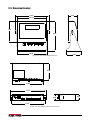
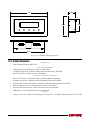
11.13 Dimension Drawings . . . . . . . . . . . . . . . . . . . . . . . . . . . . . . . . . . . . . . . . . . . . . . . . . . . . . . . . . 111
11.14 Printed Information. . . . . . . . . . . . . . . . . . . . . . . . . . . . . . . . . . . . . . . . . . . . . . . . . . . . . . . . . . . 112
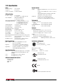
11.15 Specifications. . . . . . . . . . . . . . . . . . . . . . . . . . . . . . . . . . . . . . . . . . . . . . . . . . . . . . . . . . . . . . . 113
iii
About This Manual
This manual is intended for use by service technicians responsible for installing and servicing 720i™ digital weight
indicators. This manual applies to Version 2.00 of the 720i indicator software and Version 1.01 of the 720i Batching
indicator software.
Configuration and calibration of the indicator can be accomplished using the Revolution III® configuration utility,
serial commands, or the indicator front panel keys. See Section 3.1 on page 18 for information about configuration
methods.
Authorized distributors and their employees can view or download this manual from the Rice Lake
Weighing Systems distributor site at www.ricelake.com.
The Operator Card included with this manual provides basic operating instructions for users of the 720i. Please
leave the Operator Card with the indicator when installation and configuration are complete.
Safety
Safety Signals
Safety Symbol Definitions
Indicates a potentially hazardous situation that, if not avoided, could result in serious injury or death, and
WARNING includes hazards that are exposed when guards are removed.
CAUTION Indicates a potentially hazardous situation that, if not avoided may result in minor or moderate injury.
Indicates information about procedures that, if not observed, could result in damage to equipment or
Important corruption to and loss of data.
Safety Precautions
Do not operate or work on this equipment unless you have read and understand the instructions and
warnings in this Manual. Failure to follow the instructions or heed the warnings could result in injury or
death. Contact any Rice Lake Weighing Systems dealer for replacement manuals. Proper care is your
responsibility.
Some procedures described in this manual require work inside the indicator enclosure. These
WARNING procedures are to be performed by qualified service personnel only.
General Safety
WARNING
Failure to heed may result in serious injury or death.
DO NOT allow minors (children) or inexperienced persons to operate this unit.
DO NOT operate without all shields and guards in place.
DO NOT step on the unit.
DO NOT jump up and down on the scale.
DO NOT use for purposes other than weight taking.
DO NOT place fingers into slots or possible pinch points.
DO NOT use any load-bearing component that is worn beyond 5% of the original dimension.
DO NOT use this product if any of the components are cracked.
DO NOT exceed the rated load limit of the unit.
DO NOT make alterations or modifications to the unit.
DO NOT remove or obscure warning labels.
DO NOT use near water.
Before opening the unit, ensure the power cord is disconnected from the outlet.
Keep hands, feet and loose clothing away from moving parts.
Safety
1
1.0
Introduction
The 720i is a single-channel, programmable digital
weight indicator/controller. The configuration can be
performed using the front panel, with an attached
PS/2 ® 1 -type keyboard, or using the Revolution III
utility.
The 720i can be loaded with either PCE software or
720i batching software. Refer to Section 8.0 on page 65
or Section 9.0 on page 81 for further information on
each of these software choices.
Onboard Features
Features of the basic 720i include:
• Support for a single A/D or serial scale input.
• Eight digital I/O channels on main board, each
configurable as either input or output.
• Two serial ports on main board support duplex
RS-232 up to 115200 bps. Port 2 supports RS-232
with hardware handshaking; Port 4 supports
RS-232 and 20mA communications.
• Available in 115 VAC and 230 VAC North
American and European versions.
• Configurable print formats can be defined for up to
1000 characters each using serial commands or
Revolution III . These formats are used to print
gross or net weights, truck in/out weights,
accumulator weights, alert messages, and header
information. Additional print formats can be
created using twenty auxiliary print formats.
• Seven truck modes to store and recall weights for
gross, tare, and net printing. The truck register
contains fields for ID number, weight, and the
transaction time and date. Weights can be stored
permanently or erased at the end of the transaction.
The 720i is NTEP-certified for Classes III and III L at
10,000 divisions. See Section 11.15 on page 113 for
more information about additional certifications and
approvals.
Profibus® DP networks5 and ControlNet™6.
Part numbers of available option cards are listed in
Section 1.4 on page 5.
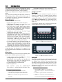
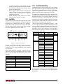
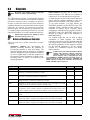
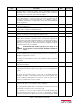
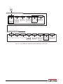
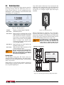
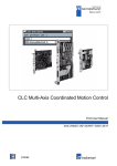
Front Panel
The 720i universal model front panel, shown in
Figure 1-1, consists of a 22-button keypad with an
L C D d i s p l a y. T h e k e y s a r e g r o u p e d a s f o u r
configurable softkeys, four scale function/navigation
keys, MENU and PRINT/Enter keys, and numeric entry
keys. The panel mount front panel is shown in
Figure 1-2.
LCD display contrast can be adjusted selecting the
Contrast Adj function from the system menu.
Figure 1-1. 720i Universal Front Panel
Option Cards
The CPU board provides one slot for installing other
option cards. Available option cards include:
• Analog output card for 0–10 VDC or 0–20 mA
tracking of gross or net weight values.
• Dual-channel serial expansion card provides one
RS-485 port or two ports for either RS-232 or
20mA communications at up to 19200 bps.
• 24-channel digital I/O expansion card.
• Ethernet option card
• Bus
interface
cards
for
EtherNet/IP™2,
DeviceNet ™ 3 , Allen-Bradley Remote I/O 4 ,
®
1. PS/2 is a registered trademark of IBM Corporation.
2. EtherNet/IP™ is a trademark of ControlNet International,
Ltd., under license by the Open DeviceNet Vendor Association.
3. DeviceNet™ is a trademark of the Open DeviceNet Vendor
Association.
2
720i Installation Manual
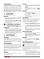
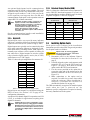
Figure 1-2. 720i Panel Mount Front Panel
Enclosures
The 720i is available in universal (tilt-stand) and panel
mount enclosures. Stainless steel enclosures are rated
for NEMA Type 4X/IP66. This manual provides
assembly drawings and replacement parts lists for the
universal model; supplemental documentation provides
information specific to the panel mount model (See
Section 1.4 on page 5).
®
®
™
4. Allen-Bradley , PLC , and SLC are trademarks of
Allen-Bradley Company, Inc., a Rockwell International company.
®
5. Profibus is a registered trademark of Profibus International.
6. ControlNet is a trademark of ControlNet International, Ltd.,
under license by the Open DeviceNet Vendor Association.
Support Applications
In addition to Revolution III, the 720i is supported by
two Windows-based applications that extend its
capabilities for batch control and database
management. ProAction PCEE , or Process Control
Engine Editor, provides functions similar to setpoint
configuration for 720i-based batch control. ProAction
DBE, the database editor, is a tool for creating, editing,
and managing databases in the 720i. Both applications
are included on the 720i Toolkit CD.
1.1
Operating Modes
The 720i has two modes of operation:
Setup mode
Most of the procedures described in this manual
require the indicator to be in setup mode, including
configuration and calibration.
To enter setup mode, press the MENU key on the
front panel, select Configuration, then press Enter.
The indicator display changes to show scale
configuration menus.
Jumper J9 (see Figure 2-3 on page 9) must be
Note installed to enable access to setup mode.
When configuration is complete, remove the
jumper (place the jumper on a single pin of J9)
to disable access to the configuration menus.
Normal mode
Normal mode is the weighing mode of the
indicator. The indicator displays gross, net, or tare
weights as required, using the secondary display to
indicate scale status and the type of weight value
displayed. Once configuration is complete, remove
jumper J9 and affix a legal seal to the fillister-head
screws on the indicator enclosure.
1.2
Indicator Operations
Basic 720i operations are summarized below:
Display Menu
Press the MENU key to show the system menu, then use
the Up or Down navigation keys to select an item from
the list. The menu provides access to audit trail
information, configuration, test operations, and display
contrast adjustment.
Toggle Gross/Net Mode
Press the GROSS/NET key to switch the display mode
from gross to net, or from net to gross. If a tare value
has been entered or acquired, the net value is the gross
weight minus the tare. If no tare has been entered or
acquired, the display remains in gross mode.
Gross mode is indicated by the letter G (gross) or, in
OIML mode, B (brutto); net mode is indicated by the
letter N.
Toggle Units
Press the UNITS key to switch between primary,
secondary, and tertiary units.
Zero Scale
1. In gross mode, remove all weight from the
scale and wait for the standstill annunciator
).
(
2. Press the ZERO key. The center of zero ( 0 )
annunciator lights to indicate the scale is
zeroed.
Acquire Tare
1. Place container on scale and wait for the
).
standstill annunciator (
2. Press the TARE key to acquire the tare weight
of the container.
3. Display shifts to net weight and shows the
letter N on the display.
Enter Tare Value
For the universal model, use the numeric keypad to key
in the tare value, then press the Tare softkey or press
and hold the front panel TARE key to enter the tare.
For the panel mount model, do the following:
1. Press and hold the GROSS/NET key for about
three seconds. When released, a zero appears.
2. Use the Up and Down navigation keys to adjust
the value (0-9 and a decimal point) and the
Right and Left navigation keys to select the
digit.
3. Press the Tare softkey or press and hold the
front panel TARE key for about three seconds,
then release to enter the tare.
Remove Stored Tare Value
1. Remove all weight from the scale and wait for
).
the standstill annunciator (
2. Press the TARE key (or, in OIML mode, the
ZERO key). Display shifts to gross weight and
shows the word Gross.
Print Ticket
1. Wait for the standstill annunciator (
).
2. Press the PRINT key to send data to the serial
port.
Select Auxiliary Print Format
Any of the auxiliary print formats (1–20) can be
selected for printed output while in weighing mode.
Note Not available in Advance Truck Mode.
For the universal model, use the numeric keypad to key
in the print format value, then press the Print softkey or
the front panel PRINT key to print using the selected
auxiliary format.
For the panel mount model, do the following:
1. Press and hold the GROSS/NET key for about
three seconds. When released, a zero appears.
2. Use the Up and Down navigation keys to adjust
the value (0-9 and a decimal point) and the
Introduction
3
and Left navigation keys to select the
digit.
3. Press the Print softkey or the front panel PRINT
key to print using the selected auxiliary format.
Right
Accumulator Functions
The accumulator must be enabled before use. Once
enabled, weight (net weight if a tare is in the system) is
accumulated whenever a print operation is performed
using the PRINT key, digital input, or serial command.
The scale must return to zero (net zero if a tare is in the
system) before the next accumulation.
The Display Accum softkey can be configured to display
the current accumulator value. Printing while the
accumulator is displayed uses the ACCFMT print
format (see Section 6.0 on page 52).
Press the CLEAR key twice to clear the accumulator.
With the panel mount version of the 720i, you
Note need to use CLR Accumulator DigIn Function
to clear the indicator.
1.3
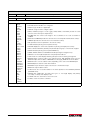
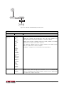
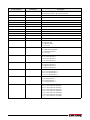
Softkey Operations
Softkeys provide additional operator functions for
specific applications. Softkey assignments are listed on
the tabs shown at the bottom of the LCD display;
softkey functions are activated by pressing the arrow
keys below the softkey tabs (see Figures 1-1 and 1-2 on
page 2).
For example, to set up a TimeDate softkey using serial
commands, do the following:
1. Place indicator in setup mode.
2. Send the following serial command:
SK#s=TimeDate
where s is the softkey position.
3. Press SaveExit (or send the KSAVEEXIT serial
command). The new softkey will appear in the
position specified by s.
4. Press the TimeDate softkey. Use the Up/Down
navigation keys to adjust the time and date
value; use the Left/Right keys to move between
fields. Time and date fields are presented in the
following order:
HOUR>MIN>[AM/PM]>MONTH>DAY>YEAR
When done, press Enter to return to weighing
mode.
The particular set of softkeys shown on the display can
be set using serial commands or Revolution III.
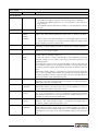
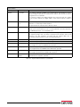
Softkey
Description
None
Not Configured, no softkeys will appear
after a none key.
<blank>
Empty Key, allows for a space/blank
between other softkeys.
Time/Date
Displays current time and date; allows
time and date change.
Display Tare
Displays tare value for the current scale
Display Accum Displays accumulator value, if enabled, for
the current scale.
Display ROC
Displays rate-of-change value, if enabled,
for the current scale.
***Weigh In
Allows truck ID entry; generates weigh-in
ticket for truck weighing applications.
***Weigh Out
Allows truck ID entry; generates weigh-out
ticket for truck weighing applications.
***Truck Regs
Displays truck register; allows deletion of
individual or all entries. Truck register can
be printed by pressing the PRINT key
while the truck register is displayed.
Alibi
Allows previous print transactions to be
recalled and reprinted.
SKUD 1-10
User-programmable keys; defined by
PCEE.
**Setpoint
Displays a menu of configured setpoints;
allows display and change of some
setpoint parameters.
**Batch Start
Starts a configured batch.
**Batch Stop
Stops a running batch and turns off all
associated digital outputs. Requires a
batch start to resume processing.
**Batch Pause Pauses a running batch. (Same as stop,
but digital outputs, if on, are not turned
off.)
**Batch Reset Stops a batch and resets it to the first
batch step.
*Weigh
Start the Weigh-In and Weigh-Out
Procedure.
*Reports
Select which report to print. There are four
sub menus under the Reports softkey:
Summary, Daily, Detail, and Code List.
*Management Add and remove materials, customers,
and source IDs and names.
More…
For applications with more than three
defined softkeys, the More… key is
automatically assigned to the fourth
softkey position. Press More… to toggle
between groups of softkeys.
* Advance Truck Mode only
** 720i Batching Version software only
*** Truck Modes 1-6 only
Table 1-1. Configurable Softkeys
4
720i Installation Manual
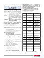
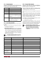
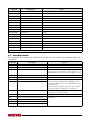
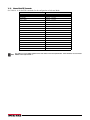
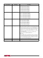
1.4
System Configurations and Options
Table 1-2 lists the 720i system models and part
numbers. All models include CPU board with one
option card slot. The 720i is a single scale unit and
cannot be upgraded to a multi-channel A/D.
System Model
Model PNs
Universal (tilt stand) model, 115/230 VAC
with PCE software
101230
Universal (tilt stand) model, 115/230 VAC,
European, CEE 7/7 power cord with PCE
software
103459
Panel mount model, 115/230 VAC (power
cord sold separately), with PCE software
101229
Universal (tilt stand) model, 115/230 VAC
with 720i Batch software
115447
Universal (tilt stand) model, 115/230 VAC,
European, CEE 7/7 power cord with 720i
Batch software
115448
Panel mount model, 115/230 VAC (power
cord sold separately), with 720i Batch
software
115449
Relay racks are available for all 720i systems. Relays
require an external enclosure for the relays. Consult
factory for details.
DC Power Supplies
Two DC power supplies are available for mobile 720i
applications:
PN 97474, 9–36 VDC supply
PN 99480, 10–60 VDC supply
Consult factory for more information.
1.5
Summary of Changes
Updates to this manual include the following:
Version 1.03
•
•
•
Table 1-2. Part Numbers for 720i Models
MINNEG and MAXNEG parameters have
been added to the ALGOUT menu (see
Section 3.2.6 on page 45) to support tracking
of negative weight values.
Added Section 9.0 on page 81 on ProAction
PCEE information.
Added print token for Alibi Numbering <AN>.
Version 1.04
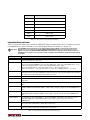
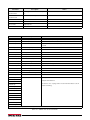
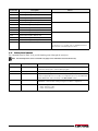
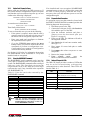
Option Cards
Table 1-3 lists the available 720i option cards. Most of
the listed option cards are installed in the expansion
card slot, J12. USB, Ethernet, and fiber-optic interface
cards are installed in connector J11.
Option Card
Relay Options
•
•
•
•
PN
Single-channel analog output card
67602
Dual serial port expansion card
67604
24-channel digital I/O expansion card
67601
Ethernet communications card
71986
EtherNet/IP communications card
87803
DeviceNet interface card
68541
Allen-Bradley Remote I/O interface card
68539
Profibus DP interface card
68540
USB interface card
93245
Fiber-optic interface card
96736
Updated the analog menu.
Added Section 8.0 on page 65 on Setpoints
(Version 2.00)
Batching (720i batching Version 1.00).
Updated Alibi Tracking Section 11.12 on
page 110.
Version 2.00
•
•
•
Added Advance Mode Section 7.6 on page 59.
Updated FEATURE menu Figure 3-13 on
page 37 to include Advance Mode.
Batching (720i batching Version 1.01).
Table 1-3. Part Numbers for 720i Option Cards
Introduction
5
2.0
Installation
This section describes procedures for connecting load
cell, digital I/O, and serial communications cables to
the 720i indicator. Assembly drawings and replacement
parts lists for the universal model are included for the
service technician. See Section 11.13 on page 111 for
dimension drawings.
CAUTION
•
•
•
2.1
Use a wrist strap to ground yourself and
protect components from electrostatic
discharge (ESD) when working inside the
indicator enclosure.
This unit uses double pole/neutral fusing
which could create an electric shock hazard.
Procedures requiring work inside the indicator
must be performed by qualified service
personnel only.
The supply cord serves as the power
disconnect for the 720i . The power outlet
supplying the indicator must be installed near
the unit and be easily accessible.
Unpacking and Assembly
Immediately after unpacking, visually inspect the 720i
to ensure all components are included and undamaged.
The shipping carton should contain the indicator, this
manual, and a parts kit. If any parts were damaged in
shipment, notify Rice Lake Weighing Systems and the
shipper immediately.
See Section 2.9 on page 11 for parts kit contents.
2.2
The 720i has no on/off switch. Before
WARNING opening the unit, ensure the power cord is
disconnected from the power outlet.
Ensure power to the indicator is disconnected, then
place the indicator face-down on an antistatic work
mat. Remove the screws that hold the backplate to the
enclosure body, then lift the backplate away from the
enclosure and set it aside.
Cable Connections
The universal model of the 720i provides six cord grips
for cabling into the indicator: one for the power cord,
five to accommodate other cabling. Install plugs in all
unused cord grips to prevent moisture from entering
the enclosure.
6
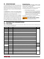
Cable Grounding
Except for the power cord, all cables routed through the
cord grips should be grounded against the indicator
enclosure. Do the following to ground shielded cables:
• Use the lock washers, clamps, and kep nuts
provided in the parts kit to install grounding
clamps on the enclosure studs adjacent to cord
grips. Install grounding clamps only for cord
grips that will be used; do not tighten nuts.
• Route cables through cord grips and grounding
clamps to determine cable lengths required to
reach cable connectors. Mark cables to remove
insulation and shield as described below:
• For cables with foil shielding, strip insulation
and foil from the cable half an inch (13 mm)
past the grounding clamp (see Figure 2-1).
Fold the foil shield back on the cable where the
cable passes through the clamp. Ensure silver
(conductive) side of foil is turned outward for
contact with the grounding clamp.
• For cables with braided shielding, strip cable
insulation and braided shield from a point just
past the grounding clamp. Strip another half
inch (13 mm) of insulation only to expose the
braid where the cable passes through the clamp
(see Figure 2-1).
NOTE: Install lockwashers
first, against backplate,
under grounding clamp
Braid
Cut insulation here
for braided cables
Enclosure Disassembly
The indicator enclosure must be opened to install
option cards and to connect cables for installed option
cards.
2.3
2.3.1
720i Installation Manual
Insulated cable
Foil (silver side out)
Grounding clamp
Cut insulation here
for foil-shielded cables
Shield wire (cut)
Length of foil before folding
back on cable insulation
Figure 2-1. Grounding Clamp Attachment for Foil-Shielded
and Braided Cabling
•
•
•
2.3.2
For load cell cables, cut the shield wire just
past the grounding clamp. Shield wire function
is provided by contact between the cable shield
and the grounding clamp.
Route stripped cables through cord grips and
clamps. Ensure shields contact grounding
clamps as shown in Figure 2-1. Tighten
grounding clamp nuts.
Finish installation using cable ties to secure
cables inside of indicator enclosure.
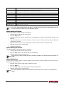
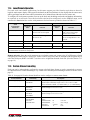
Load Cells
To attach cable from a load cell or junction box to the
720i, route the cable through the cord grip and ground
the shield wire as described in Section 2.3.1 on page 6.
Next, remove load cell connector J1 from CPU board.
Wire the load cell cable from the load cell or junction
box to the connector as shown in Table 2-1.
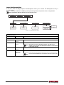
Serial Communications
Communications ports on the 720i CPU board support
PS/2-type remote keyboard, full duplex RS-232, and
20 mA output communications at up to 115200 bps.
Optional communications cards support USB,
Ethernet, and fiber-optic connections to the 720i.
To attach serial communications cables, route the cable
through the cord grip and ground the shield wire as
described in Section 2.3.1 on page 6. Remove the serial
connector from the CPU board and wire to the
connector. Once cables are attached, plug the connector
into the header on the board. Use cable ties to secure
serial cables to the inside of the enclosure.
Table 2-2 shows the pin assignments for Ports 1, 2, and
4. Port 1 supports remote keyboard attachment of PS/
2-type personal computer keyboards (see Section 11.9
on page 109 for information about the PS/2 keyboard
interface.) Port 3 uses connector J4 to provide a
dedicated display port for both universal and panel
mount versions of the 720i.
Connector
Pin
Signal
Port
J3
1
CLK
1
2
+5V
3
GND
4
DATA
–EXC
+EXC
–SENS
+SENS
–SIG
+SIG
J1 LOAD CELL CONNECTOR
2.3.3
1
GND
Figure 2-2. Load Cell Connector
J2
2
RS-232 RxD
If using 6-wire load cell cable (with sense wires),
remove jumpers JP1 and JP2 before reinstalling
connector J1. For 4-wire installation, leave jumpers
JP1 and JP2 on.
When connections are complete, reinstall load cell
connector on the CPU board header and use two cable
ties to secure the load cell cable to the inside of the
enclosure.
3
RS-232 TxD
4
RS-232 RTS
5
RS-232 CTS
6
GND
1
RS-422/485 Y
2
RS-422/485 Z
3
RS-422/485 B
4
RS-422/485 A
5
+6V
6
GND
J1 Connector Pin
Function
1
+SIG
2
–SIG
3
+SENSE
4
–SENSE
5
+EXC
6
–EXC
• For 6-wire load cell connections, remove jumpers JP1
and JP2.
Table 2-1. Load Cell Connector Pin Assignments
J4
J5
1
GND
2
RS-232 RxD
3
RS-232 TxD
4
20mA OUT
2
3
4
Table 2-2. Serial Port Pin Assignments
Serial ports are configured using the SERIAL menu.
See Section 3.2.2 on page 33 for configuration
information.
Installation
7
An optional dual-channel serial communications
expansion card, PN 67604, is also available. The serial
expansion card provides two additional serial ports,
assigned as port numbers 7 and 8. One port on the
serial expansion card supports four-wire RS-485
communications. Both ports on the expansion card can
support RS-232 or 20mA connections.
2.3.5
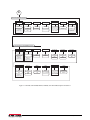
Detached Display Module (DDM)
Table 2-4 shows the connections between connector J4
on the 720i CPU board and connector J3 (Com 1) on
the detached display module (DDM) board. See board
diagrams in Figures 2-3 and 2-4, on page 9.
DDM Com 1
J3 Connector
Installation of option cards in connector J11
Note requires removal of the PORT2/OPTI port
CPU Board
J4 Connector
Pin
Signal
Pin
Signal
1
A
1
Y
2
B
2
Z
3
Z
3
B
See the communications interface card installation
instructions for more information.
4
Y
4
A
5
+6V
5
+6V
2.3.4
6
GND
6
GND
selection jumper (see Figure 2-3 on page 9).
Install the jumper to enable RS-232
communications through connector J2;
remove the jumper to enable an USB,
fiber-optic, or Ethernet option card installed in
connector J11.
Digital I/O
Digital inputs can be set to provide many indicator
functions, including all keypad functions. Digital
inputs are active low (0 VDC), inactive high (5 VDC).
Digital outputs are typically used to control relays that
drive other equipment. Outputs are designed to sink,
rather than source, switching current. Each output is a
normally open collector circuit, capable of sinking 24
mA when active. Digital outputs are wired to switch
relays when the digital output is active (low, 0 VDC)
with reference to a 5 VDC supply.
Table 2-3 shows the pin assignments for connector J6.
J6 Pin
J6 Signal
1
+5 VDC
2
GND
3
DIO 1
4
DIO 2
5
DIO 3
6
DIO 4
7
DIO 5
8
DIO 6
9
DIO 7
10
DIO 8
Table 2-3. J6 Pin Assignments (Digital I/O)
Digital inputs and outputs are configured using the
DIG I/O menu. See Section 3.2.5 on page 43 for
configuration information.
An optional 24-channel digital I/O expansion card, PN
67601, is available for applications requiring more
digital I/O channels.
A digital I/O point can be configured to count
Note active pulse inputs by setting the bit to INPUT
(DIG I/O menu) and using PCEE to monitor the
bit. However, the fastest pulse rate that can be
counted using a digital input is 10Hz (10 pulses
per second).
8
720i Installation Manual
Table 2-4. CPU Board—DDM Connections
2.4
Installing Option Cards
Each option card is shipped with installation
instructions specific to that card. The general procedure
for all option cards is as follows:
Option cards are not hot-pluggable.
CAUTION Disconnect power to the 720i before
installing option cards.
1. Disconnect power to the indicator. Remove
backplate as described in Section 2.2 on
page 6.
2. Carefully align the option card connector with
connector J12 or J11 on the CPU board (see
Figure 2-3 on page 9). Press down to seat the
option card in the CPU board connector.
3. Use the screws provided in the option kit to
secure the other end of the option card to the
threaded standoffs on the CPU board (see
Figure 2-3).
4. Make connections to the option card as
required. Use cable ties to secure loose cables
inside the enclosure. When installation is
complete , reassemble the enclos ure as
described in Section 2.6 on page 10.
The 720i automatically recognizes all installed option
cards when the unit is powered on. No
hardware-specific configuration is required to identify
the newly installed card to the system.
J9
J10
SW1
J12
BATTERY
POWER SUPPLY
CONNECTOR
EXPANSION CARD SLOT
J8
J11
COMMUNICATIONS
OPTION CARD SLOT
J7
JUMPER ON TO ENABLE J2,
OFF TO ENABLE J11
HEARTBEAT
LED
LOAD CELL SENSE
JUMPERS
J1
J3
J2
LOAD CELL CONNECTOR
J4
SERIAL PORT 2 SERIAL PORT 1 SERIAL PORT 3
PS/2
DISPLAY
J5
J6
SERIAL PORT 4
DIGITAL I/O
Figure 2-3. 720i CPU Board
COM 1
COM 0
CPU Interface Port
Programming Port
Figure 2-4. 720i Display Board
Installation
9
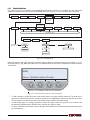
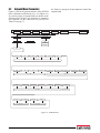
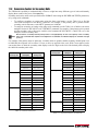
2.5
Slot Assignments
Table 2-5 lists the slot numbers, CPU board connectors, and configuration assignments made for both onboard and
expansion card functions in the 720i. See Figure 2-3 for connector locations.
Slot Number
0
Connector
Function
Configured As
Connector J6
Onboard digital I/O
Slot 0, bits 1–8
Connectors J3, J2, J5
Onboard serial communications
Ports 1, 2, 4
1
Connector J1
Onboard single-channel A/D
Channel 1
2
Connectors J12 (expansion card
slot) and J11(communications
option card slot)
Dual-channel serial expansion card
Ports 7–8
Digital I/O expansion card
Slot 2, bits 1–24
Analog output card
Analog 2
Bus communications cards
Bus Option 2
Table 2-5. 720i Slot Assignments
2.6
Enclosure Reassembly
2.7
Once cabling is complete, position the backplate over
the enclosure and reinstall the backplate screws. Use
the torque pattern shown in Figure 2-5 to prevent
distorting the backplate gasket. Torque screws to 15
in-lb (1.7 N-m).
9
7
5
2
4
11
12
3
Torque backplate screws
to 15 in-lb (1.7 N-m)
6
8
1
10
Figure 2-5. 720i Enclosure Backplate
Torqued screws may become less tight as
Important the gasket is compressed during torque
pattern, therefore a second torque is
required using the same pattern and
torque value.
10
720i Installation Manual
CPU Board Removal
If you must remove the 720i CPU board, use the
following procedure:
1. Disconnect power to the indicator. Remove
backplate as described in Section 2.2 on
page 6.
2. Unplug connectors for power to the board,
serial communications, digital I/O, and any
installed option cards.
3. Remove any installed option cards.
4. Remove the five phillips head screws and the
kep nut from the CPU board.
5. Remove CPU board from the enclosure. If
necessary, cut cable ties to shift cables out of
the way.
To replace the CPU board, reverse the above
procedure. Be sure to reinstall cable ties to secure all
cables inside the indicator enclosure.
2.8
Battery Replacement
Replacement Procedure
The lithium battery on the CPU board maintains the
real-time clock and protects data stored in the system
RAM when the indicator is not connected to AC power.
Data protected by the CPU board battery includes time
and date, truck and tare memory, and onboard database
information.
Use Revolution III™ to store a copy of the indicator
configuration on a PC before attempting battery
replacement. If any data is lost, the indicator
configuration can be restored from the PC.
Watch for the low battery warning on the LCD display
and periodically check the battery voltage on both the
CPU board and on any installed memory option cards.
Batteries should be replaced when the indicator low
battery warning comes on, or when battery voltage falls
to 2.2 VDC. Life expectancy of the battery is ten years.
For best results, replace the battery while in weigh
mode and with AC power applied. Use care not to
bend the battery retaining spring.
If the battery must be replaced with power removed, do
the following immediately after restoring power:
1. Place indicator in setup mode.
2. Go to the Version menu and press the RSConfig
softkey. If connected using Revolution III ,
configuration can be reset by using monitor
mode to enter the RESETCONFIGURATION
command followed by the RS command.
See Figure 2-3 on page 9 for CPU board battery
location and orientation (positive side up).
Risk of explosion if battery is replaced
WARNING with incorrect type. Dispose of batteries
per manufacturer instruction.
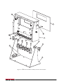
2.9
Replacement Parts and Assembly Drawings
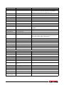
2.9.1
Universal Model
Table 2-6 lists replacement parts and parts kit contents for the 720i universal enclosure model, including all parts
referenced in Figures 2-6 through 2-8.
Ref Number
PN
1
101257
Switch panel membrane, universal (1)
2
53308
Model/serial number label (1)
3
101263
Enclosure, universal (1)
4
103988
Tilt stand washers (2), in parts kit
5
103610
Tilt stand knobs (2), in parts kit
6
67531
Tilt stand (1)
7
15628
Cord grip, 1/2 NPT (1)
8
15626
Cord grips, PG9 (3)
9
15630
Lock nut for 1/2 NPT cord grip (1)
10
68600
Cord grip, PG11 (1)
11
15627
Lock nuts, PCN9 (3)
12
68601
Lock nut, PG11 (1)
13
45043
Ground wire, 4 in w/ No. 8 eye connector (1)
14
102887
Display board assembly, universal (1)
2-7
15
85202
Power cord assembly, 115 VAC and 230 VAC North American units (1)
2-6
85203
Power cord assembly, 230 VAC European units (1)
—
67885
Standoffs, M-F, 4-40NC x 3/4 (2)
2-7
17
14618
Kep nuts, 4-40NC hex (3)
18
103443
CPU board mounting strip (1)
19
106788
720i CPU board (PCE Version) (1)
20
102376
Backplate gasket, universal (1)
21
75062
Sealing washers (4)*
22
14862
Machine screws, 8-32NC x 3/8 (4)*
16
Description (Quantity)
See Figure
2-6
2-7
Table 2-6. Universal Model Replacement Parts
Installation
11
Ref Number
PN
Description (Quantity)
23
14626
Kep nuts, 8-32NC (7)*
2-8
24
53307
Label (1)
2-7
25
69291
3V Lithium coin battery
26
103989
Standoffs, F-F, 4-40 x 1.06 (3)
27
14825
Machine screws, 4-40NC x 1/4 (18)
28
102888
LCD display module, 240x64, universal (1)
29
16861
High voltage warning label (1)
30
67796
Power supply cable assembly, to CPU board (1)
31
67613
Power supply, ±6VDC, 25W (1)
32
103442
Power supply bracket (1)
33
103936
Component plate (1)
2-6
35
16892
Ground/Earth label (1)
2-8
36
15134
Lock washers, No. 8, Type A (3)
37
30376
Nylon seal ring for 1/2 NPT cord grip (1)
38
30375
Nylon seal rings for PG9 cord grips (3)
39
68599
Nylon seal ring for PG11 cord grip (1)
40
102377
Enclosure backplate, universal (1)
2-7
—
103458
Ribbon cable assembly, 7 in, 20-pin female, universal (1)
—
—
103609
Cable assembly, CPU-to-display, universal (1)
—
* Additional parts included in parts kit.
Universal Model Parts Kit Contents
104033
720i Software Tool Kit CD (1)
103988
Tilt stand washers (2)
103610
Tilt stand knobs (2)
42149
Rubber feet for tilt stand (4)
30623
Machine screws, 8-32NC x 7/16 (3)
14626
Kep nuts, 8-32NC (4)
14862
Machine screws, 8-32NC x 3/8 (5)
15134
Lock washers, No. 8, Type A (4)
15631
Cable ties (5)
15665
Reducing gland for 1/2 NPT cord grip (1)
19538
Cord grip plugs (4)
53075
Cable shield ground clamps (4)
75062
Sealing washers (8)
71344
10-position screw terminal for J6 (1)
76513
4-position screw terminals for J3 and J5 (2)
76514
6-position screw terminals for J1, J2 and J4 (3)
94422
Capacity label (1)
Table 2-6. Universal Model Replacement Parts (Continued)
12
720i Installation Manual
See Figure
2-6
33
1
2
12
13
3
11
39
10
9
4
38
8
37
7
5
15
6
Figure 2-6. 720i Universal Model Assembly, Enclosure and Tilt Stand
Installation
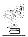
13
30
27
28
31
32
29
26
25
From Power Supply
40
14
24
16
19
20
21
22
Figure 2-7. 720i Universal Model, CPU Board and Backplate
Ground wire (13)
to backplate (22)
23
35
36
Grounding Stack
Ground wire from
power cord (15)
Figure 2-8. 720i Universal Model, Grounding Detail
14
720i Installation Manual
17
18
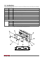
2.9.2
Panel Mount Controller
Table 2-7 lists replacement parts and parts kit contents for the 720i panel mount controller, including all parts
referenced in Figure 2-9 on page 16.
Ref Number
PN
Description (Quantity)
1
103314
Panel mount controller cover (1)
2
103677
Panel mount controller connector label (1)
3
101263
Enclosure, universal (1)
3
67796
Power supply cable assembly, to CPU board (1)
4
69291
3V Lithium coin battery
5
106788
720i CPU board assembly (PCE Version) (1)
6
14822
Machine screws, 4-40NC x 1/4 (10)
7
101264
Panel mount controller enclosure (1)
8
53308
Labels (2)
9
14825
Machine screws, 4-40NC x 1/4 (2)
10
103681
AC feed-through header (1)
11
16892
Ground/Earth label (1)
12
15601
Ground wire, 6 in w/ No. 8 eye connector (1)
13
67885
Standoffs, M-F 4-40NC x 1.25 (2)
14
67613
Power supply, ±6VDC, 25W (1)
15
85494
Power supply cover (1)
16
16861
High voltage warning label (1)
17
54206
Machine screw, fillister head, 6-32NC x 3/8 (1)
18
14626
Kep nuts, 8-32NC hex (2)
19
14839
Machine screws, 6-32NC x 1/4 (2)
20
53307
Label (1)
21
15134
Lock washers, No. 8, Type A (2)
22
71698
Polyurethane foam strip (1)
Panel Mount Controller Parts Kit Contents
104033
720i Software Toolkit CD (1)
15888
3-position terminal block (1)
71344
10-position screw terminal for J6 (1)
76513
4-position screw terminals for J3 and J5 (2)
76514
6-position screw terminals for J1, J2 and J4 (3)
14626
Kep nut, 8-32NC hex (1)
14862
Machine screws, 8-32NC x 3/8 (2)
15134
Lock washers, No. 8 Type A (7)
15694
No. 8 crimp connector (1)
53075
Cable shield ground clamps (4)
30623
Machine screws, fillister head, 8-32NC x 7/16 (2)
94422
Capacity label (1)
Table 2-7. Panel Mount Controller Replacement Parts
Installation
15
20
19
1
18
17
22
2
16
3
15
14
13
4
12
5
6
21
11
10
9
7
8
Figure 2-9. Panel Mount Controller Assembly
16
720i Installation Manual
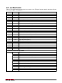
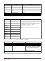
2.9.3
Panel Mount Display
Table 2-8 lists replacement parts and parts kit contents for the 720i panel mount remote display unit, including all
parts referenced in Figure 2-10.
Ref Number
PN
Description (Quantity)
1
101256
Switch panel membrane, panel mount display (1)
2
101265
Faceplate, panel mount display (1)
3
68719
Faceplate gasket, panel mount display (1)
4
102605
Backplate, panel mount display (1)
5
14822
Machine screws, 4-40NC x 1/4 (6)
6
101239
Remote display board assembly (1)
7
53308
Label (1)
8
69787
Clinching bracket (1)
9
82426
Backing plate, panel mount display (1)
Panel Mount Remote Display Parts Kit Contents
76514
6-position screw terminal (1)
94422
Capacity label (1)
53075
Cable shield ground clamp (1)
71522
Machine screws, 8-32NC x 1/4 (4)
82425
Machine screws, 10-32NF x 1.50 (7)
Table 2-8. Panel Mount Display Unit Replacement Parts
6
5
1
2
4
3
7
8
9
Figure 2-10. 720i Panel Mount Display Assembly
Installation
17
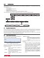
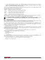
3.0
Configuration
To configure the 720i indicator, press the MENU key on
the front panel (only if jumper J9 is installed), press the
Down key to select Configuration , then press Enter .
Detailed descriptions of the configuration menus are
provided in Section 3.2 on page 20.
When configuration is complete, press the Save & Exit
softkey to exit setup mode. Save & Exit writes all
parameter changes to NV RAM before returning to
normal mode.
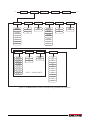
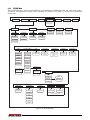
3.1
Menu:
Audit Trail
Configuration
Test Operations
Contrast Adj.
Save & Exit
Exit
Figure 3-1. 720i Menu Display
Configuration Methods
The 720i indicator can be configured by using the front
panel keys to navigate through a series of configuration
menus or by sending commands or configuration data
to an indicator serial port. Configuration using the
menus is described in Section 3.1.3 on page 19.
Configuration using the serial port can be
accomplished using either the serial command set
described in Section 10.1 on page 86 or the Revolution
III® configuration utility and there are two software
modules available:
• 720i PCE
• 720i Batching
2. With both indicator and PC powered off,
connect the PC serial port to the RS-232 pins
on the indicator serial port or to the optional
USB communications card.
3. Power up the PC and the indicator. To enter
setup mode, see “Configuration” above.
4. Start the Revolution III program.
Some configuration parameters cannot be
Note accessed through the configuration menus.
Revolution III provides the most complete
and efficient configuration interface for the
720i.
3.1.1
Revolution Configuration
The Revolution III configuration utility provides the
preferred method for configuring the 720i indicator.
Revolution III runs on a personal computer to set
configuration parameters for the indicator. When
Revolution III configuration is complete, configuration
data is downloaded to the indicator.
Revolution III supports both uploading and
downloading of indicator configuration data. This
capability allows configuration data to be retrieved
from one indicator, edited, then downloaded to another
indicator with an identical hardware configuration.
To use Revolution III, do the following:
1. Install Revolution III on an IBM-compatible
personal computer. See Section 5.0 on page 50
for detailed hardware and software
requirements.
18
720i Installation Manual
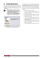
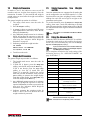
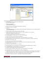
Figure 3-2. Revolution III Display for 720i PCE Version
Revolution III provides online help for each of its
configuration displays. Parameter descriptions
provided in this manual for front panel configuration
can also be used when configuring the indicator using
Revolution III : The interface is different, but the
parameters set are the same.
See Section 5.0 on page 50 for more information about
using Revolution III to configure the 720i.
3.1.2
Serial Command Configuration
The serial command set can be used to configure the
720i indicator using either a personal computer,
terminal, or remote keyboard. Like Revolution III ,
serial command configuration sends commands to the
indicator serial port; unlike Revolution III , serial
commands can be sent using any external device
capable of sending ASCII characters over a serial
connection.
Serial commands duplicate the functions available
using the indicator front panel and provide some
functions not otherwise available. Serial commands
can be used to simulate pressing front panel keys, to
configure the indicator, or to dump lists of parameter
settings. See Section 10.1 on page 86 for more
information about using the serial command set.
3.1.3
Front Panel Configuration
By default, the 720i is configured to use the installed
single-channel A/D as the source for Scale 1. To
configure the 720i for serial scale support, use the
CONFIG submenu under the SCALES menu.
For example: to configure a serial scale, set the serial
input function (SERIAL menu) for Port 4 (or Port 7, if
using a serial expansion card) to SCALE or INDUST
(see Section 3.2.2 on page 33). Return to the top-level
SCALES menu, then go Down to Scale 1
Configuration, Right to CONFIG (Scale Hardware
Configuration), then Down once more to show the scale
source options. Use the Right or Left navigation key to
change the default A/D value to PORT 4 (or PORT 7) as
shown in Figure 3-3.
CONFIG
PORT 4
Figure 3-3. Scale Hardware Configuration Display
See Section 11.3 on page 102 for more information
about configuring serial scales.
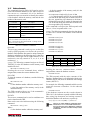
3.1.4
Multi-Range and Multi-Interval Scales
The 720i supports multi-range and multi-interval scales
of either two or three ranges or intervals.
Multi-range scales provide two or three ranges, each
extending from zero to the maximum capacity
specified for the range, that can specify different scale
display divisions. The scale interval range changes as
the applied weight increases but does not reset to lower
range until the scale returns to zero.
Multi-interval scales divide the scale into two or three
partial weighing ranges, each with different scale
display divisions. The scale interval changes with both
increasing and decreasing loads applied.
To configure a multi-range or multi-interval scale, use
the SPLIT parameter to select 2RNG or 3RNG (for
multi-range scales), or 2INTVL or 3INTVL (for
multi-interval scales). Selecting a SPLIT value other
than OFF allows specification of decimal point, display
divisions, and maximum capacity for each range or
interval.
The SPLIT parameter is used to enable multi-range or
multi-interval. The SPLIT parameter is in the SCALES
menu, see Figure 3-7, and Table 3-2. After setting the
SPLIT parameter, the Format menu selection will
change as shown in Figure 3-9, and Table 3-4.
If using streaming with multi-range or multi-interval,
the stream must be set to Custom in Revolution III. The
Tokens for Secondary and Tertiary Units must be set to
L or K to match the Primary, refer to the Serial Menu,
Tokens Parameter, in Section 3.2.2 on page 33. They
can be set using Revolution III or through the front
panel.
In multi-range, each range has its own capacity and
display division, extending from zero. The scale
display division will increase at the entered range
capacities, either two or three ranges. Once the range
has increased to the next level, the display division will
remain in new range until the scale returns to zero. The
tare value can be taken in any range.
For example,
Range 1 is 0 - 3000 x 1 lb.
Range 2 is 0 - 10,000 x 5 lb.
In multi-interval, the scale has one capacity, which is
segmented into weighing intervals, either two or three
intervals, each with different display division sizes. As
the weight value exceeds an interval or set interval, the
display division will increase, as the weight falls below
an interval or set interval, the display division will
decrease. The tare can only be taken in the first
interval.
For example,
Range 1 is 0-30 x 0.01 lb.
Range 2 is 30 - 60 x 0.02 lbs.
Configuration
19
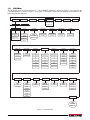
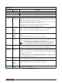
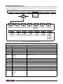
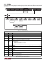
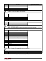
3.2
Menu Structures and Parameter Descriptions
The 720i indicator can be configured using a series of menus accessed through the indicator front panel when the
indicator is in setup mode. Table 3-1 summarizes the functions of each of the main menus.
Menu
Menu Function
SCALES
Configuration
Configure and calibrate scale
SERIAL
Serial
Configure communications ports
FEATURE
Feature
Set date and time formats, truck mode, passwords, keyboard locks, regulatory mode, and
initial consecutive number value, and define softkeys.
PFORMT
Print Format
Set port used for header, gross, net, truck in/out, and auxiliary print ticket formats. See
Section 6.0 on page 52 for more information.
SETPTS
Setpoints
Configure setpoints and batching mode. Only available in the 720i Batching version.
DIG I/O
Digital I/O
Assign digital input/output functions
ALGOUT
Analog Output
Configure analog output module. Used only if analog output option is installed.
VERSION
Version
Display installed software version number. The RSConfig softkey on the Version menu can
be used to restore all configuration parameters to their default values.
Table 3-1. 720i Menu Summary
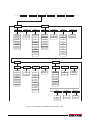
The following sections provide graphic representations of the 720i menu structures and tables describing the menu
parameters. Default values are shown in bold type; numeric ranges and string values are shown in italic type.
Parameters shown surrounded by a dotted-line box only appear under the special circumstances explained under
each box.
SCALES
SERIAL
FEATURE
PFORMT
SETPTS
DIG I/O
ALGOUT
VERS
720i Batching
Version only
see page 57
Figure 3-4. Configuration Menu Flow
Move UP
Move LEFT / Previous
Move DOWN
Move RIGHT / Next
Access MENU
ENTER value
Figure 3-5. Front Panel Key Functions in Setup Mode
Four front panel keys are used as directional keys to navigate through the menus in setup mode (see Figure 3-5).
The UNITS and TARE keys scroll left and right (horizontally) on the same menu level; ZERO and GROSS/NET move
up and down (vertically) to different menu levels. The PRINT key serves as an Enter key for selecting parameter
values within the menus. Press the MENU key to show the system menu. A label on each of these keys identifies the
direction provided by the key when navigating through the setup menus.
20
720i Installation Manual
1st Level
Parameter
1st Level
Parameter
2nd Level
Parameter
2nd Level
Parameter
Default value
Value
Value
Value
When moving through values below the first menu level, press
to return to the
level above. Press
or
to move to the next parameter on the level above.
Figure 3-6. Setup Mode Menu Navigation
To select a parameter, press or to scroll left or right until the desired menu group appears on the display, then
press to move down to the submenu or parameter you want. When moving through the menu parameters, the
default or previously selected value appears first on the display.
Configuration
21
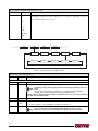
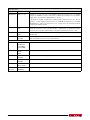
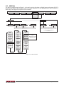
3.2.1
SCALES Menu
The SCALES menu is shown in Figure 3-7. The FORMAT submenu is shown in Figure 3-8 on page 26; the
CALIBR submenu is shown in Figure 3-10 on page 32. Parameters shown in each diagram are described in the
table following that diagram.
SCALES
SCALE 1
SERIAL
FEATURE
PFORMT
CONFIG
GRADS
SPLIT
10000
number
OFF
2RNG
Specify for
SPLIT = OFF
3RNG
2INTVL
3INTVL
DIG I/O
SETPTS
ALGOUT
VERS
720i Batching
Version only
see page 57
FORMAT
See
FORMAT
Submenu
ZTRKBND
ZRANGE
MOTBAND
SSTIME
0
number
1.900000
number
1
number
10
number
OVRLOAD
WMTTHRH
DIGFLT1
DIGFLT2
DIGFLT3
DFSENS
DFTHRH
FS+2%
FS+1D
1000
number
4
8
4
8
4
8
2OUT
4OUT
NONE
2D
16
32
64
128
256
1
2
16
32
64
128
256
1
2
16
32
64
128
256
1
2
8OUT
16OUT
32OUT
64OUT
128OUT
5D
10D
20D
50D
100D
200D
250D
FS+9D
FS
RATTRAP
SMPRAT
PWRUPMD
TAREFN
ACCUM
VISIBL
PEAK HOLD
OFF
ON
30HZ
120HZ
GO
DELAY
BOTH
NOTARE
OFF
ON
ON
OFF
OFF
NORMAL
240HZ
480HZ
960HZ
7.5HZ
15HZ
60HZ
PBTARE
KEYED
BI-DIR
AUTO
CALIBR
See
CALIBR
Submenu
Figure 3-7. SCALES Menu
22
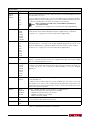
720i Installation Manual
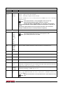
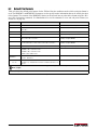
SCALES Menu
Parameter
Choices
Description
Level 2 submenus
SCALE 1
Allows configuration and calibration of each scale
CONFIG
Scale hardware configuration (A/D or serial scale)
Level 3 submenus
GRADS
10000
1–9999999
Specifies the number of full scale graduations if SPLIT=OFF. (For multi-range and
multi-interval scales (SPLIT OFF), the GRADS value is derived from the capacity and
display divisions specified for the range or interval.)
The value entered must be in the range 1–9999999 and should be consistent with legal
requirements and environmental limits on system resolution.
To calculate GRADS, use the formula: GRADS = Capacity / Display Divisions.
Display divisions are specified under the FORMAT submenu.
SPLIT
OFF
2RNG
3RNG
2INTVL
3INTVL
Specifies whether the scale is full-range (OFF), multi-range (2RNG, 3RNG), or multi-interval
(2INTVL, 3INTVL). For multi-range and multi-interval scales, see the submenu shown in
Figure 3-9 on page 30 and parameter descriptions in Table 3-4 on page 31.
FORMAT
PRIMAR
SECNDR
TERTIA
ROC
For standard scales (SPLIT=OFF), see Level 4 submenu descriptions in Table 3-3 on
page 27.
ZTRKBND
0
number
Automatically zeroes the scale when within the range specified, as long as the input is
within the ZRANGE and scale is at standstill. Specify the zero tracking band in ± display
divisions. Maximum legal value varies depending on local regulations.
For scales using linear calibration, do not set the zero tracking band
Note to a value greater than that specified for the first linearization point.
ZRANGE
1.900000
number
Selects the range within which the scale can be zeroed. The 1.900000 default value is ±
1.9% around the calibrated zero point, for a total range of 3.8%. Indicator must be at
standstill to zero the scale. Use the default value for legal-for-trade applications.
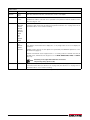
MOTBAND
1
number
Sets the level, in display divisions, at which scale motion is detected. If motion is not
detected for 1 second or more, the standstill symbol lights. Some operations, including
print, tare, and zero, require the scale to be at standstill. Maximum legal value varies
depending on local regulations.
For multi-range and multi-interval scales, see Table 3-4 on page 31.
If this parameter is set to 0, the standstill annunciator will be set continuously on, and
operations including zero, print, and tare will be performed regardless of scale motion. If 0 is
selected, ZTRKBND must also be set to 0.
SSTIME
10
number
Specifies the length of time the scale must be out of motion, in 0.1-second intervals, before
the scale is considered to be at standstill. Values greater than 10 are not recommended.
OVRLOAD
FS+2%
FS+1D
FS+9D
FS
Determines the point at which the display blanks and an out-of-range error message is
displayed. Maximum legal value varies depending on local regulations.
WMTTHRH
1000
number
Specifies the minimum number of grads required for a weighment to be added to the
recorded number of weighments.
Table 3-2. SCALES Menu Parameters
Configuration
23
SCALES Menu
Parameter
DIGFLT1
DIGFLT2
DIGFLT3
Choices
Description
4
8
16
32
64
128
256
1
2
Selects the digital filtering rate used to reduce the effects of mechanical vibration from the
immediate area of the scale.
2OUT
4OUT
8OUT
16OUT
32OUT
64OUT
128OUT
Digital filter cutout sensitivity. Specifies the number of consecutive readings that must fall
outside the filter threshold (DFTHRH parameter) before digital filtering is suspended.
NONE
2D
5D
10D
20D
50D
100D
200D
250D
Digital filter cutout threshold. Specifies the filter threshold, in display divisions. When a
specified number of consecutive scale readings (DFSENS parameter) fall outside of this
threshold, digital filtering is suspended. If NONE is selected, the filter is always enabled.
RATTRAP
OFF
ON
Enables RATTLETRAP® digital filtering. RATTLETRAP is most effective at filtering repeating
vibrations caused by mechanical noise from nearby machines but may increase settling
times over standard digital filter selections.
SMPRAT
30HZ
120HZ
240HZ
480HZ
960HZ
7.5HZ
15HZ
60HZ
Sample rate. Selects measurement rate, in samples per second, of the analog-to-digital
converter. Lower sample rate values provide greater signal noise immunity: the default 120
Hz value may be too fast to provide the desired stability in some static weighing
applications.
PWRUPMD
GO
DELAY
Power up mode. In GO mode, the indicator goes into operation immediately after a brief
power up display test.
DFSENS
DFTHRH
Choices indicate the number of A/D conversions per update that are averaged to obtain the
displayed reading. A higher number gives a more accurate display by minimizing the effect
of a few noisy readings, but slows down the settling rate of the indicator.
When configuring non-A/D scales, set the DIGFLTx parameters to
Note 1 to disable filtering.
See Section 11.7 on page 107 for more information about digital filtering.
See Section 11.7 on page 107 for more information about digital filtering.
See Section 11.7 on page 107 for more information about digital filtering.
In DELAY mode, the indicator performs a power up display test, then enters a 30-second
warm up period. If no motion is detected during the warm up period, the indicator becomes
operational when the warm up period ends; if motion is detected, the delay timer is reset
and the warm up period repeated.
TAREFN
BOTH
NOTARE
PBTARE
KEYED
Enables or disables push-button and keyed tares. Possible values are:
BOTH: Both push-button and keyed tares are enabled
NOTARE: No tare allowed (gross mode only)
PBTARE: Push-button tares enabled
KEYED: Keyed tare enabled
ACCUM
OFF
ON
Accumulator. Specifies whether the scale accumulator is enabled. If enabled, accumulation
occurs whenever a print operation is performed.
VISIBL
ON
OFF
Scale visibility. Specifies whether scale data is displayed.
Table 3-2. SCALES Menu Parameters (Continued)
24
720i Installation Manual
SCALES Menu
Parameter
PEAK HOLD
Choices
OFF
NORMAL
BI-DIR
AUTO
Description
Peak hold. Used to determine, display, and print the greatest net weight read during a
weighing cycle. The weighing cycle ends when a print command is executed (AUTO setting)
or when the peak weight is cleared by pressing ZERO or PRINT. Press GROSS/NET to
display gross weight data when using the peak hold function.
OFF
Peak hold function is off.
NORMAL Positive peak, manual reset. Greatest net weight is held in memory until the
weight is removed from the scale and either the ZERO or PRINT key is pressed.
BI-DIR
Bi-directional peak, manual reset. Same as NORMAL, but peak value can be
either positive or negative, determined by absolute value.
AUTO
Positive peak, auto print, auto reset. Automatic print occurs when scale load is 0
± 10 display divisions and at standstill. Following the print command, the peak
value is cleared and reset automatically.
CALIBR
WZERO
WVAL
WSPAN
WLIN
REZERO
See Level 4 submenu descriptions in Table 3-5 on page 32 and Section 4.2 on page 47.
Table 3-2. SCALES Menu Parameters (Continued)
Configuration
25
…
GRADS
SPLIT
PRIMAR
FORMAT
ZTRKBND
ZRANGE
SECNDR
DECPNT
DSPDIV
UNITS
DECPNT
DSPDIV
UNITS
MULT
8888888
8888880
1D
2D
5D
888888.8
8888888
8888880
2D
5D
1D
KG
G
OZ
TN
T
GR
troyoz
troylb
LT
CUSTOM
OFF
NONE
lb
0.453592
number
8888800
8.888888
88.88888
888.8888
8888.888
88888.88
888888.8
LB
KG
G
OZ
TN
T
GR
troyoz
troylb
LT
CUSTOM
OFF
NONE
8888800
8.888888
88.88888
888.8888
8888.888
88888.88
TERTIA
ROC
DECPNT
DSPDIV
UNITS
MULT
DECPNT
DSPDIV
MULT
888888.8
8888888
8888880
2D
5D
1D
KG
G
OZ
TN
T
GR
troyoz
troylb
LT
CUSTOM
OFF
NONE
lb
0.453592
number
8888888
8888880
1D
2D
5D
1.000000
number
8888800
8.888888
88.88888
888.8888
8888.888
88888.88
8888800
8.888888
88.88888
888.8888
8888.888
88888.88
888888.8
UNITS
INTERVL
REFRESH
SEC
10
0.100000
MIN
HOUR
number
number
Figure 3-8. SCALES Menu, FORMAT Submenu, SPLIT = OFF
26
…
MOTBAND
720i Installation Manual
SCALES Menu, FORMAT Submenu, SPLIT = OFF
Parameter
Choices
Description
Level 4, FORMAT submenu
PRIMAR
DECPNT
DSPDIV
UNITS
Specifies the decimal position, display divisions, and units used for the primary units. See
Level 5 submenu parameter descriptions.
SECNDR
DECPNT
DSPDIV
UNITS
MULT
Specifies the decimal position, display divisions, units, and conversion multiplier used for the
secondary units. See Level 5 submenu parameter descriptions.
TERTIA
DECPNT
DSPDIV
UNITS
MULT
Specifies the decimal position, display divisions, units, and conversion multiplier used for the
tertiary units. See Level 5 submenu parameter descriptions.
ROC
DECPNT
DSPDIV
MULT
TIME
INTERVL
REFRESH
Specifies the decimal position, display divisions, conversion multiplier, time units, update
interval, and refresh interval used for the rate of change units. See Level 5 submenu
parameter descriptions.
Level 5 submenus
Primary Units (PRIMAR) Parameters
DECPNT
8888888
8888880
8888800
8.888888
88.88888
888.8888
8888.888
88888.88
888888.8
Decimal point location. Specifies the location of the decimal point or dummy zeroes in the
primary unit display. Value should be consistent with local legal requirements.
DSPDIV
1D
2D
5D
Display divisions. Selects the minimum division size for the primary units displayed weight.
UNITS
LB
KG
G
OZ
TN
T
GR
troyoz
troylb
LT
CUSTOM
NONE
OFF
Specifies primary units for displayed and printed weight. Values are: LB=pound;
KG=kilogram; G=gram; OZ=ounce; TN=short ton; T=metric ton; GR=grain; troyoz=troy
ounce; troylb=troy pound; LT=long ton.
Table 3-3. SCALES Menu, FORMAT Submenu Parameters, SPLIT = OFF
Configuration
27
SCALES Menu, FORMAT Submenu, SPLIT = OFF
Parameter
Choices
Description
Secondary Units (SECNDR) and Tertiary Units (TERTIA) Parameters
DECPNT
888888.8
8888888
8888880
8888800
8.888888
88.88888
888.8888
8888.888
88888.88
Decimal point location. Determines the location of the decimal point or dummy zeros in the
secondary or tertiary units display.
DSPDIV
2D
5D
1D
Display divisions. Selects the value of minimum division size of the displayed weight for
secondary or tertiary units display.
UNITS
LB
KG
G
OZ
TN
T
GR
troyoz
troylb
LT
CUSTOM
NONE
OFF
Specifies secondary or tertiary units for displayed and printed weight. Values are:
LB=pound; KG=kilogram; G=gram; OZ=ounce; TN=short ton; T=metric ton; GR=grain;
troyoz=troy ounce; troylb=troy pound; LT=long ton.
MULT
0.453592
0.000001–
9999999
Multiplier. Specifies the conversion factor by which the primary units are multiplied by to
obtain the secondary or tertiary units. The default is 0.453592, which is the conversion
factor for changing pounds to kilograms. See Section 11.8 on page 108 for a list of
multipliers.
To shift between primary, secondary, and tertiary units, press the UNITS key.
Rate of Change (ROC) Units Parameters
For applications using the ROC function, the primary scale should be configured with a finer resolution than the rate of change
(ROC) units to prevent a stepwise appearance in the ROC display. The ROC display step size (weight increment between
displayed values) can be roughly calculated as follows:
(updates_per_ROC_UNIT) * (PRIMARY_resolution / ROC_resolution)
For example, with INTERVL=30; REFRESH =0.1; UNITS=MIN; PRIMARY resolution at 0.1 LB and ROC resolution at 1.0 (LB/
MIN):
-
INTERVL * REFRESH = 30 * 0.1 = 3.0 seconds per update (ROC data is flushed every 3.0 seconds)
-
With UNITS = MIN, there are 20 ROC data updates per ROC time unit: 60 seconds / 3.0 seconds per update
-
The resolution ratio of PRIMARY to ROC units is 0.1 (0.1 / 1.0)
-
This configuration provides a step size in the ROC display of 2 LB (2 LB increments between displayed values):
20 * 0.1 = 2
Note that setting both PRIMARY and ROC display resolutions to 1 LB would have resulted in a step size of 20 LB.
Table 3-3. SCALES Menu, FORMAT Submenu Parameters, SPLIT = OFF (Continued)
28
720i Installation Manual
SCALES Menu, FORMAT Submenu, SPLIT = OFF
Parameter
Choices
Description
DECPNT
8888888
8888880
8888800
8.888888
88.88888
888.8888
8888.888
88888.88
888888.8
Decimal point location. Determines the location of the decimal point or dummy zeros in the
display.
DSPDIV
1D
2D
5D
Display divisions. Selects the minimum division size for the ROC units displayed weight.
MULT
1.0
0.000001–
9999999
Multiplier. Specifies the conversion factor by which the primary units are multiplied by to
obtain the displayed rate of change units.
UNITS
SEC
MIN
HOUR
Rate-of-change units.
INTERVL
10
1–100
Update interval. Specifies the number of refreshes over which the rate-of-change is
calculated.
See Section 11.8 on page 108 for information about conversion factors.
For example, with REFRESH set to 0.1 second and INTERVL at 60, each weight value takes
6 seconds (0.1 * 60) to be flushed from the ROC data.
REFRESH
0.1
0.1–60
Refresh interval. Specifies the number of seconds between rate-of-change samples.
Table 3-3. SCALES Menu, FORMAT Submenu Parameters, SPLIT = OFF (Continued)
Configuration
29
…
SPLIT
FORMAT
ZTRKBND
ZRANGE
…
MOTBAND
MAX1
DECPT2
DDIV2
1D
2000
888888.8
2D
5000
8888880
2D
weight
8888888
5D
weight
8888800
5D
8888880
1D
DECPT1
DDIV1
8888888
8.888888
8888800
88.88888
8.888888
888.8888
88.88888
8888.888
888.8888
88888.88
8888.888
888888.8
88888.88
UNITS
DECPT3
DDIV3
MAX3
888888.8
2D
10000
LB
8888888
5D
weight
KG
8888880
1D
G
8888800
OZ
8.888888
TN
88.88888
T
GR
888.8888
troyoz
8888.888
88888.88
MAX2
If SPLIT = 3RNG or 3INTVL
troylb
LT
CUSTOM
OFF
NONE
Figure 3-9. FORMAT Submenu, SPLIT OFF (Multi-range and Multi-interval Scales)
30
720i Installation Manual
SCALES Menu, FORMAT Submenu, SPLIT OFF
Parameter
Choices
Description
Level 4, FORMAT submenu
DECPT1
8888888
8888880
8888800
8.888888
88.88888
888.8888
8888.888
88888.88
888888.8
Decimal point location for first range or interval. Specifies the location of the decimal point or
dummy zeroes in the primary unit display. Value should be consistent with local legal
requirements.
DDIV1
1D
2D
5D
Display divisions for first range or interval. Selects the minimum division size for the primary
units displayed weight.
MAX1
2000
weight
Maximum weight for first range or interval.
DECPT2
888888.8
8888888
8888880
8888800
8.888888
88.88888
888.8888
8888.888
88888.88
Decimal point location for second range or interval. Specifies the location of the decimal
point or dummy zeroes in the primary unit display. Value should be consistent with local legal
requirements.
DDIV2
2D
5D
1D
Display divisions for second range or interval. Selects the minimum division size for the
primary units displayed weight.
MAX2
5000
weight
Maximum weight for second range or interval.
DECPT3
888888.8
8888888
8888880
8888800
8.888888
88.88888
888.8888
8888.888
88888.88
Decimal point location for third range or interval (SPLIT = 3RNG or 3INTVL only). Specifies
the location of the decimal point or dummy zeroes in the primary unit display. Value should
be consistent with local legal requirements.
DDIV3
2D
5D
1D
Display divisions for third range or interval (SPLIT = 3RNG or 3INTVL only). Selects the
minimum division size for the primary units displayed weight.
MAX3
10000
weight
Maximum weight for third range or interval (SPLIT = 3RNG or 3INTVL only).
Table 3-4. SCALES Menu, FORMAT Submenu Parameters, SPLIT OFF
Configuration
31
SCALES Menu, FORMAT Submenu, SPLIT OFF
Parameter
Choices
UNITS
LB
KG
G
OZ
TN
T
GR
troyoz
troylb
LT
CUSTOM
NONE
OFF
Description
Specifies primary units for displayed and printed weight. Values are: LB=pound;
KG=kilogram; G=gram; OZ=ounce; TN=short ton; T=metric ton; GR=grain; troyoz=troy
ounce; troylb=troy pound; LT=long ton.
Table 3-4. SCALES Menu, FORMAT Submenu Parameters, SPLIT OFF (Continued)
…
VISIBLE
…
CALIBR
GRADS
FORMAT
WZERO
WVAL
WSPAN
WLIN
REZERO
POINT 3
POINT 4
POINT 5
POINT 1
POINT 2
Figure 3-10. SCALES Menu, CALIBR Submenu
SCALES Menu, CALIBR Submenu
Parameter
Choices
Description
Level 4, CALIBR submenu
WZERO
—
Press ENTER to display and edit the zero calibration A/D count or millivolts value.
WVAL
—
Press ENTER to display and edit the test weight value.
If unable to change value using keypad, use the following method to enter new
Note value:
To enter new value use the up/down keys to change the first digit to desired
number. Then use the key pad to enter the rest of the numbers.
Example: To enter 25000 change the first number using up/down arrows to 2. Then use the keypad and
enter 5000. The result will be 25000.
WSPAN
—
Press ENTER to display and edit the span calibration A/D count or millivolts value.
WLIN
POINT 1 —
POINT 5
Press ENTER to display and edit test weight and calibration values for up to five linearization points.
—
Press ENTER to remove an offset value from the zero and span calibrations.
Use this parameter only after WZERO and WSPAN have been set. See
Note Section 4.2 on page 47 for more information about using this parameter.
REZERO
Perform linear calibration only after WZERO and WSPAN have been set.
Table 3-5. SCALES Menu, CALIBR Submenu Parameters
32
720i Installation Manual
3.2.2
SERIAL Menu
See Section 11.6 on page 106 for information about 720i serial data formats.
SCALES
SERIAL
FEATURE
PFORMT
…
PORT 2
DIG I/O
SETPTS
ALGOUT
VERS
720i Batching
Version only
see page 57
CMD
BAUD
BITS
TERMIN
STOP BITS
ECHO
RESPONSE
EOLDLY
9600
19200
8NONE
7EVEN
CR/LF
CR
2
1
ON
OFF
ON
OFF
0
number
28800
38400
57600
7ODD
8ODD
8EVEN
115200
300
600
1200
2400
4800
HANDSHK
STREAM
SOURCE
SFMT
OFF
XONXOFF
HRDWAR
OFF
LFT
List of
configured
scales
720i Batching Version only
INDUST
4KEYS
KEYPAD
format
If STREAM ≠ OFF
DISPLAY
Figure 3-11. SERIAL Menu, Port 2
Configuration
33
SCALES
SERIAL
FEATURE
PFORMT
DIG I/O
SETPTS
ALGOUT
VERS
720i Batching
Version only
see page 57
Optional Ports 7 or 8
PORT 4
CMD
SCALE
…
IND SC
See CMD Selections
BAUD
BITS
TERMIN
STOP BITS
ECHO
RESPONSE
EOLDLY
HANDSHK
9600
19200
28800
38400
57600
115200
300
600
1200
2400
4800
8NONE
7EVEN
7ODD
8ODD
8EVEN
CR/LF
CR
2
1
ON
OFF
ON
OFF
0
number
OFF
XONXOFF
Only when in Command Mode
RS-485 can be specified
for PORT 7
(serial expansion card) only
PORTTYPE
DUPLEX
ADDRESS
232
485
HALF
FULL
0
number
If PORTTYPE = 485
TOKENS
STREAM
SFMT
OFF
LFT
INDUST
4KEYS
KEYPAD
DISPLAY
format
720i Batching Version only
PRIMAR
TARE
Selectable token characters
If STREAM = LFT or INDUST
If PORT = CMD
Figure 3-12. SERIAL Menu, Port 4 and Expansion Ports
34
720i Installation Manual
If PORT = CMD
720i Batching Version only
SERIAL Menu
Parameter
Choices
Description
Level 2 submenus
PORT 2
PORT 4
CMD
SCALE
IND SC
Specifies the type of data received by the port:
SCALE: Legal-for-trade serial scale input
IND SC: Industrial (non-legal-for-trade) scale input
KEYBD is available only on Port 1; SCALE, IND SC are available only on Port 4 and higher
(expansion ports).
The keyboard interface is not hot-pluggable. Power-off the 720i
Note before attaching keyboard cable to the Port 1 connector.
DO NOT EDIT PORT 3 PARAMETERS. Port 3 provides communications
with the detached display module (DDM); changing these parameters will disable the
display.
Print format outputs default to Port 4; if using Port 4 for other scale connections,
reassign needed print formats to another port before configuring.
Level 3 Submenus
Ports 2 and 4
BAUD
9600
19200
28800
38400
57600
115200
300
600
1200
2400
4800
Baud rate. Selects the transmission speed for the port.
BITS
8NONE
7EVEN
7ODD
8ODD
8EVEN
Selects number of data bits and parity of data transmitted or received by the port.
STOP BITS
2
1
Selects number of stop bits transmitted or received by the port.
ECHO
ON
OFF
Specifies whether characters received by the port are echoed back to the sending unit.
RESPONSE
ON
OFF
Specifies whether the port transmits replies to serial commands.
TERMIN
CR/LF
CR
Termination character. Selects termination character for data sent from the port.
EOLDLY
0
0–255
End-of-line delay. Sets the delay period, in 0.1-second intervals, from when a formatted line is
terminated to the beginning of the next formatted serial output. Value specified must be in the
range 0-255, in tenths of a second (10 = .1 second).
HANDSHK
OFF
XONOFF
HRDWAR
Specifies whether XON/XOFF flow control characters or hardware handshaking is used.
232
485
Specifies whether the port is used for RS-232 or RS-485 communications. If 485 is selected
(Port 7 only), additional prompts are shown to specify half- or full-duplex operation and
RS-485 address.
RS-485 communications can be specified for Port 7 (serial expansion card)
Note only.
PORTTYPE
The maximum baud rate for ports on serial expansion cards
Note (port number greater than 4) is 19200.
Hardware handshaking is available only on Port 2.
Table 3-6. Serial Menu Parameters
Configuration
35
SERIAL Menu
Parameter
Choices
Description
DUPLEX
HALF
FULL
Specifies whether the RS-485 communications is half- or full-duplex.
ADDRESS
0
0–255
Specifies the decimal indicator address for RS-485 connections. RS-232 communications is
disabled if an address other than zero is specified for this parameter. RS-485 addresses must
be in the range 01–255.
TOKENS
PRIMAR
SECNDR
TERTIA
GROSS
INVALID
MOTION
ZERO
NET
OK
RANGE
TARE
If STREAM is set to LFT or INDUST, the TOKENS parameter can be used to replace tokens
used in the data stream from the indicator front panel. See Section 11.5 on page 103 for more
information about custom stream formatting.
STREAM
OFF
LFT
INDUST
4KEYS
KEYPAD
Specifies what data, if any, is streamed from the port.
LFT updates streamed data at the display rate, so only weight values shown on the display are
streamed.
INDUST streams data at the A/D update rate specified by the SMPRATE parameter on the
SCALES menu (page 22).
4KEYS and KEYPAD stream keypad events to a receiving indicator. KEYPAD transmits all
keypad events; 4KEYS transmits key presses of the ZERO, GROSS/NET, TARE, and UNITS
keys only.
Streaming is not supported for RS-485 connections.
Note The print key always prints locally.
SFMT
format
Specifies the stream format used for the streamed data (CMD scale type). The default format
is the Rice Lake format (see Section 11.6 on page 106). See Section 11.5 on page 103 for
information about custom stream formatting.
Table 3-6. Serial Menu Parameters (Continued)
36
720i Installation Manual
3.2.3
FEATURE Menu
The FEATURE menu is used to set miscellaneous system attributes, including time and date, truck mode, softkey
definitions, and parameters relating to the regulatory environment. See Table 3-7 on page 38 for parameter
descriptions.
SCALES
SERIAL
FEATURE
PFORMT
DIG I/O
SETPTS
ALGOUT
VERS
720i Batching
Version only
see page 57
DATE
TIME
DATEFMT
DATESEP
TIMEFMT
TIMESEP
MMDDYYYY
DDMMYYYY
YYYYMMDD
YYYYDDMM
SLASH
DASH
SEMI
12HOUR
24HOUR
COLON
COMMA
TRUCK
OFF
MODE1
MODE2
MODE3
MODE4
MODE5
MODE6
ADVANCE
DAY START
DAY END
HHMMSS
ADVANCE MODE
ALIBI
CFGPWD
VEHICLE
OFF
ON
0
number
MATERIAL
CUSTOMER
SOURCE
DELIVERY
DELIVERY WGT
REMARKS
PRINT
REPRINT
SHIFTS
DAY
SERIAL
NUMBER
DECFMT
CONSNUM
CONSTUP
DOT
COMMA
0
number
0
number
SOFTKEYS
KYBDLK
ZERONLY
OFF
ON
OFF
ON
List of
available and
configured
softkeys
SHIFT 1 - 3
SHIFT # START
SHIFT # END
HHMMSS
REGULAT
NTEP
CANADA
INDUST
NONE
OIML
See
INDUST
Submenu
REGWORD
HEARTBEAT
LOCALE
LATUDE
ELEVAT
GROSS
BRUTTO
OFF
0.5
1.0
1.5
2.0
2.5
3.0
3.5
4.0
OFF
ON
45
number
345
number
If LOCALE = ON
Figure 3-13. FEATURE Menu
Configuration
37
FEATURE Menu
Parameter
Choices
Description
Level 2 submenus
DATE
DATEFMT
DATESEP
Allows selection of date format and date separator character. See Level 3 submenu
parameter descriptions.
Use the TIME/DATE softkey or the SD serial command to set the date. See Section 10.0
on page 86 for information about using the serial commands.
TIME
TIMEFMT
TIMESEP
Allows selection of time format and separator character. See Level 3 submenu parameter
descriptions.
Use the TIME/DATE softkey or the ST serial command to set the time. See Section 10.1
on page 86 for information about using the serial commands.
DECFMT
DOT
COMMA
Specifies whether decimal numbers are displayed using a period (DOT) or comma as the
decimal symbol.
CONSNUM
0
0–9999999
Consecutive numbering. Allows sequential numbering for print operations. The
consecutive number value is incremented following each print operation that includes
<CN> in the ticket format. When the consecutive number is reset, it is reset to the value
specified on the CONSTUP parameter.
CONSTUP
0
0–9999999
Specifies the consecutive number start-up value used when the consecutive number is
reset by sending the KCLRCN serial command or a CLRCN digital input. Value specified
must be in the range 0–9 999 999.
TRUCK
OFF
MODE1
MODE2
MODE3
MODE4
MODE5
MODE6
ADVANCE
Specifies the truck mode used. If selected, the indicator switches from normal mode to
the selected truck mode. See Section 7.0 on page 58 for more information about using
the truck modes.
MODE1: Auto clear ID, keyed tares, value swapping
MODE2: Auto clear ID, no keyed tares, value swapping
MODE3: Stored ID, keyed tares, value swapping
MODE4: Stored ID, no keyed tares, value swapping
MODE5: Stored ID, keyed tares, no value swapping
MODE6: Stored ID, no keyed tares, no value swapping
ADVANCE: Enables the advance mode.
Modes 1 - 6 have stored tare weight by Truck ID, Advance mode does
Note not have stored tare weight, only stored transactions.
ADVANCE
MODE
VEHICLE
MATERIAL
CUSTOMER
SOURCE
DELIVERY
DELIVERY WGT
REMARKS
PRINT
REPRINT
SHIFTS
DAY
SERIAL NUMBER
ON or OFF, default is ON
ON or OFF, default is ON
ON or OFF, default is ON
ON or OFF, default is ON
ON or OFF, default is ON
ON or OFF, default is ON
ON or OFF, default is ON
ON, OFF or PROMPT, default is ON
ON or OFF
SHIFT 1, SHIFT 2, SHIFT 3
DAY START, DAY END
Enter Serial Number (Ticket Serial Number) 0-99999999 (Default is 0)
See Table 7-2 on page 59 for more information on each prompt.
ALIBI
OFF
ON
Specifies whether data storage is used by the alibi feature to allow reprinting any
transaction.
Use the SOFTKEYS parameter to enable a softkey for recalling alibi print transactions.
See Section 11.12 on page 110 for more information about using the alibi feature.
Table 3-7. FEATURE Menu Parameters
38
720i Installation Manual
FEATURE Menu
Parameter
CFGPWD
Choices
0
0–9999999
reset=999999
Description
Configuration password. Specify a non-zero value to restrict access to all configuration
menus and PCE.
If a configuration password is specified, be sure to record the password
Note and keep it in a safe place. If the configuration password is lost or
unavailable, the indicator must be cleared (reset configuration and
calibration parameters) to continue use.
To clear the indicator, press the setup switch, then enter 999999 (six nines) at the
configuration password prompt. The unit performs a RESETCONFIGURATION then
returns to the setup mode configuration display.
KYBDLK
OFF
ON
Keyboard lock. Specify ON to disable the keypad in normal mode.
ZERONLY
OFF
ON
Zero key only. Specify ON to disable all front panel keys except ZERO in normal mode.
SOFTKEYS
None
<blank>
Time/Date
Display Tare
Display Accum
Display ROC
Alibi
Softkeys provide additional operator functions for specific applications. Assignments are
listed on the tabs shown at the bottom of the LCD display; functions are activated by
pressing the arrow keys below the softkey tabs.
Setpoint
Batch Start
Batch Stop
Batch Pause
Batch Reset
These features are only available with the 720i Batching version software.
Weigh
Reports
Management
These features are available with the Advanced Truck Mode Only.
Weigh In
Weigh Out
Truck Regs
These features are available with the Truck Modes 1-6 Only.
SKUD
1-10
User-programmable softkeys; defined by PCEE.
REGULAT
NTEP
CANADA
INDUST
NONE
OIML
Regulatory mode. Specifies the regulatory agency having jurisdiction over the scale site.
REGWORD
GROSS
BRUTTO
• OIML, NTEP, and CANADA modes allow a tare to be acquired at any weight greater
than zero. NONE allows tares to be acquired at any weight value.
• OIML, NTEP, and CANADA modes allow a tare to be cleared only if the gross weight
is at no load. NONE allows tares to be cleared at any weight value.
• NTEP and OIML modes allow a new tare to be acquired even if a tare is already
present. In CANADA mode, the previous tare must be cleared before a new tare can
be acquired.
• NONE, NTEP and CANADA modes allow the scale to be zeroed in either gross or net
mode as long as the current weight is within the specified ZRANGE. In OIML mode,
the scale must be in gross mode before it can be zeroed; pressing the ZERO key in
net mode clears the tare.
• INDUST provides a set of subparameters to allow customization of tare, clear, and
print functions in non-legal-for-trade scale installations. See Level 4 parameter
descriptions in Table 3-8 on page 41.
The value specified for this parameter affects the function of the front panel TARE and
ZERO keys. See Section 11.2 on page 101 for a complete description of TARE and ZERO
key functions for each of the regulatory modes.
Sets the term displayed when weighing in gross mode. Selecting BRUTTO replaces the
Gross annunciator with Brutto.
Table 3-7. FEATURE Menu Parameters (Continued)
Configuration
39
FEATURE Menu
Parameter
Choices
HEARTBEAT
OFF, 0.5—4.0
Description
Specifies, in seconds, the rate of the heartbeat signal sent from the host to the display
module. The heartbeat is used to verify active communications between the host and the
display and to ensure that the displayed data is current.
If specified, the display module input heartbeat (HB1:I parameter) must also be set,
typically to a value slightly longer than the host HEARTBEAT parameter. (For example,
HEARTBEAT=1.5, HB1:I=2.0.) See Section 11.11 on page 110 for more information about
configuring the display module.
LOCALE
OFF
ON
Locale. Set this parameter ON to enable the LATUDE and ELEVAT parameters. Specifying
latitude and elevation of the scale site provides compensation for gravitational effects.
Attached scales must be recalibrated after changing this parameter from OFF to ON.
LATUDE
45
0–90
Latitude. Specify the latitude of the scale site in degrees. This parameter is shown only if
LOCALE=ON.
ELEVAT
345
±0–9999
Elevation. Specify the elevation of the scale site in meters. Valid values are –9999 through
9999. This parameter is shown only if LOCALE=ON.
Level 3 submenus
DATEFMT
MMDDYYYY
DDMMYYYY
YYYYMMDD
YYYYDDMM
Specifies the format used to display or print the date.
DATESEP
SLASH
DASH
SEMI
Specifies the date separator character.
TIMEFMT
12HOUR
24HOUR
Specifies the format used to display or print the time.
TIMESEP
COLON
COMMA
Specifies the time separator character.
SHIFT 1 - 3
SHIFT # START
SHIFT # END
Specifies the shift start and end time in 24 hour format (HHMMSS)
DAY START
DAY END
HHMMSS
HHMMSS
Specifies the day start and end time in 24 hour format (HHMMSS)
Table 3-7. FEATURE Menu Parameters (Continued)
40
720i Installation Manual
FEATURE Menu, REGULAT/INDUST Submenu
The INDUST setting of the REGULAT parameter allows customization of several tare, clear, and print functions
for use in non-legal-for-trade scale installations. See Section 11.2 on page 101 for more information about
regulatory mode functions.
SCALES
SERIAL
FEATURE
PFORMT
DIG I/O
SETPTS
ALGOUT
VERS
720i Batching
Version only
see page 57
REGULAT
INDUST
SNPSHOT
HTARE
ZTARE
KTARE
MTARE
NTARE
CTARE
DISPLAY
SCALE
NO
YES
NO
YES
YES
NO
REPLACE
REMOVE
NOTHING
NO
YES
YES
NO
PRTMOT
PRTPT
PRTHLD
HLDWGH
MOTWGH
OVRBASE
AUDAGNCY
NO
YES
NO
YES
NO
YES
NO
YES
NO
YES
CALIB
SCALE
NTEP
CANADA
INDUST
NONE
OIML
Figure 3-14. REGULAT / INDUST Submenu
FEATURE Menu, REGULAT / INDUST Submenu
Parameter
Choices
Description
Level 4, REGULAT / INDUST submenu
SNPSHOT
DISPLAY, SCALE
Display or Scale weight source.
HTARE
NO, YES
Allow tare in display hold
ZTARE
NO, YES
Remove tare on ZERO
KTARE
YES, NO
Always allow keyed tare
MTARE
REPLACE
REMOVE
NOTHING
Multiple tare action
NTARE
NO, YES
Allow negative or zero tare
CTARE
YES, NO
Allow CLEAR key to clear tare/accumulator
PRTMOT
NO, YES
Allow print while in motion
PRTPT
NO, YES
Add PT to keyed tare print
PRTHLD
NO, YES
Print during display hold
HLDWGH
NO, YES
Allow truck weighment during display hold
MOTWGH
NO, YES
Allow truck weighment in motion
OVRBASE
CALIB, SCALE
Zero base for overload calculation
AUDAGNCY
NTEP
CANADA
INDUST
NONE
OIML
Audit trail display agency format.
Table 3-8. REGULAT / INDUST Submenu Parameters
Configuration
41
3.2.4
PFORMT Menu
The PFORMT menu can be used to set the port used by each print format. Print formats can be viewed or edited
using Revolution III, serial commands or the front panel. See Section 6.0 on page 52 for detailed information about
print formatting.
SCALES
SERIAL
FEATURE
PFORMT
SETPTS
DIG I/O
ALGOUT
VERS
720i Batching
Version only
see page 57
720i
Batching Version
Software Only
GFMT
NFMT
ACCFMT
TRWIN
SPFMT
TRWOUT
TRFMT
See GFMT Menu
HDRFMT1
FMT
HDRFMT2
AUXFMT
PORT
AUX1FMT
PORT 4
PORT
PORT 2
PORT 4
PORT 2
Figure 3-15. PFORMT Menu
42
720i Installation Manual
...
AUX20FMT
Same as AUXFMT1
ALERT
3.2.5
DIG I/O Menu
The DIG I/O menu shown in Figure 3-16 is used to assign functions to digital inputs and outputs. SLOT 0
represents the eight I/O bits available on the CPU board (connector J6). The additional slot, with 24 I/O bits, is
shown only if the digital I/O expansion card is installed.
SCALES
SERIAL
FEATURE
PFORMT
SETPTS
DIG I/O
ALGOUT
VERS
720i Batching
Version only
see page 57
…
SLOT 0
BIT 1
BIT 2
SLOT 2
…
BIT 3
BIT 8
Same as BIT 1
BIT 1
…
BIT 24
Same as SLOT 0, BIT 1
If DIG I/O Expansion Board
Is Installed
OFF
INPUT
OUTPUT
ZERO
NT/GRS
TARE
UNITS
PRINT
ACCUM
SETPT*
TIMDATE
ESC
CLEAR
DSPTAR
KEY1
KEY2
KEY3
KEY4
KEY5
KEY6
KEY7
KEY8
KEY9
KEYDP
KEY0
ENTER
NAVUP
NAVDN
NAVLFT
NAVRGT
KBDLOC
HOLD
BATRUN
BATSTRT
BATPAUS
BATRESET
BATSTOP
CLRCN
GROSS
NET
PRIM
SEC
TER
CLRTAR
CLRACC
*720i
Batching Version
Software Only
Figure 3-16. DIG I/O Menu
Configuration
43
DIG I/O Menu
Parameter
Choices
Description
Level 2 submenus
SLOTx
BIT y
Lists available digital I/O slots.
Level 3 submenus
BIT y
OFF
INPUT
OUTPUT
ZERO
NT/GRS
TARE
UNITS
PRINT
ACCUM
SETPTS
TIMDATE
ESC
CLEAR
DSPTAR
KEY0—KEY9
KEYDP
ENTER
NAVUP
NAVDN
NAVLFT
NAVRGT
KBDLOC
HOLD
*BATRUN
*BATSTRT
*BATPAUS
*BATRESET
*BATSTOP
CLRCN
GROSS
NET
PRIM
SEC
TER
CLRTAR
CLRACC
Specifies the function of the digital I/O bit.
•
•
•
•
•
•
•
•
•
•
•
•
•
•
•
•
•
•
•
•
•
•
•
•
OFF indicates that the bit is not configured.
INPUT assigns the bit as a digital input.
OUTPUT assigns the bit as a digital output.
ZERO, NT/GRS (net/gross mode toggle), TARE, UNITS, and PRINT provide the same
functions as the five major front panel keys.
ACCUM adds the current scale weight to the accumulator, if the scale accumulator is
enabled.
SETPTS and TIMDATE provide the same function as the Setpoint and Time/Date softkeys.
TIMDATE provides the same function as the Time/Date softkey.
ESC provides a function equivalent to the Cancel softkey.
CLEAR simulates pressing the front panel CLR key.
DSPTAR displays the current tare; equivalent to pressing the Display Tare softkey.
KEY0—KEY9 and KEYDP (decimal point) simulate pressing keys on the numeric keypad.
ENTER simulates pressing the front panel ENTER key.
NAVUP, NAVDN, NAVLFT, and NAVRGT simulate pressing the navigation keys.
KBDLOC locks the keyboard (indicator front panel) when held low.
HOLD holds the current display. Releasing this input clears the running average filter.
BATRUN allows a batch routine to be started and run. With BATRUN active (low), the
BATSTRT input starts the batch; if BATRUN is inactive (high), BATSTRT resets the batch.
BATSTRT starts or resets a batch routine, depending on the state of the BATRUN input.
BATPAUS pauses a batch routine when held low.
BATRESET stops the batch sequence and resets to the first batch step.
BATSTOP stops the batch routine.
CLRCN resets the consecutive number to the value specified on the CONSTUP parameter
(FEATURE menu).
GROSS, NET, PRIM, SEC, and TER select gross or net weight display, and primary,
secondary, or tertiary units display modes.
CLRTAR clears the current tare for the active scale.
CLRACC clears the active accumulator.
* 720i Batching Software Version Only
Table 3-9. DIG I/O Menu Parameters
44
720i Installation Manual
3.2.6
ALGOUT Menu
If the analog output option is installed, configure all other indicator functions and calibrate the indicator itself
before configuring the analog output. See the Analog Output Card Installation Instructions, PN 69089, for more
information.
SCALES
SERIAL
FEATURE
PFORMT
SETPTS
DIG I/O
ALGOUT
VERS
720i Batching
Version only
see page 57
ALGOUT2
SOURCE1
MODE
OFFSET
ERRACT
MIN
MINNEG
MAX
MAXNEG
SCALE 1
GROSS
NET
0%
20%
FULLSC
HOLD
000000
number
OFF
number
10000
number
OFF
number
ZEROSC
If SOURCE1≠ PROG
TWZERO
TWSPAN
40
number
59650
number
Figure 3-17. Analog Output Menu
ALGOUT Menu
Parameter
Choices
Description
Level 2 submenus
SOURCE1
SCALE
Specifies the scale tracked by the analog output.
MODE
GROSS
NET
Specifies the weight data, gross or net, tracked by the analog output.
OFFSET
0%
20%
Zero offset. Select 0% for 0–10 V or 0–20 mA output; select 20% for 4–20 mA output. This
parameter must be set before calibrating the analog output.
ERRACT
FULLSC
HOLD
ZEROSC
Error action. Specifies how the analog output responds to system error conditions.
Possible values are:
FULLSC: Set to full value (10 V or 20 mA)
HOLD: Hold current value
ZEROSC: Set to zero value (0 V or 4 mA)
MIN
000000
0–9999999
Specifies the minimum weight value tracked by the analog output. Specify a value in the range 0–
9999999.
MINNEG
OFF
ON
Specifies the minimum negative weight value tracked by the analog output.
MAX
10000
0–9999999
Specifies the maximum weight value tracked by the analog output. Specify a value in the range 0–
9999999
MAXNEG
OFF
ON
Specifies the maximum negative weight value tracked by the analog output.
TWZERO
40
0–65535
Tweak zero. Enter tweak value to adjust the analog output zero calibration. Use a multimeter to
monitor the analog output value.
TWSPAN
59650
0-65535
Tweak span. Enter tweak value to adjust the analog output span calibration. Use a multimeter to
monitor the analog output value.
Table 3-10. Analog Output Menu Parameters
Configuration
45
3.2.7
FLDBUS Menu
The FLDBUS menu is shown only if a DeviceNet, Profibus, EtherNet/IP, or ControlNet option card is installed.
The SWAP parameter on the FLDBUS menu enables byte swapping by the PCEE BusCommand handler rather
than requiring a SWP (SWAPBYTE) instruction in the PLC.
• YES swaps bytes within the word before transmission to the scanner
• NO disables swapping
The DATASIZE parameter sets the size of the BusCommand handler data transfers. The default value (8 bytes)
matches the default data size specified in the EDS and GSD files, and used by the standard discrete transfer
commands. DATASIZE can be set to any value from 2–128 bytes (1–64 words), but the value specified must match
the data size set for the PLC Scanner I/O data size.
SCALES
SERIAL
FEATURE
PFORMT
SETPTS
DIG I/O
FLDBUS
VERS
720i Batching
Version only
see page 57
SWAP
DATASIZE
NO
YES
8
data_size
Figure 3-18. FLDBUS Menu
FLDBUS Menu
Parameter
Choices
Description
Level 2 submenus
SWAP
NO
YES
Specifies byte-swapping used for the fieldbus card.
DATASIZE
8
2-128
Specifies the data size, in bytes, that the BusCommand handler transfers. If this parameter is set to
a value other than the default (8 bytes), ensure that it matches the Scanner I/O data size specified
for the PLC.
Table 3-11. Fieldbus Menu Parameters
3.2.8
VERS Menu
The VERS menu can be used to check the installed software version or, by using the RSConfig (reset configuration)
softkey, to restore all configuration parameters to their factory default values. There are no parameters associated
with the Version menu: when selected, the indicator displays the installed software version number.
SCALES
SERIAL
FEATURE
PFORMT
SETPTS
720i Batching
Version only
see page 57
Figure 3-19. Version Menu
46
720i Installation Manual
DIG I/O
ALGOUT
VERS
Software
version
4.0
Calibration
The 720i can be calibrated using the front panel, serial commands, or Revolution III®. Each method consists of the
following steps:
• Zero calibration
• Entering the test weight value
• Span calibration
• Optional five-point linearization
• Optional rezero calibration for test weights using hooks or chains
The following sections describe the calibration procedure for each of the calibration methods.
SCALES
SERIAL
FEATURE
PFORMT
DIG I/O
ALGOUT
VERS
SCALE 1
CALIBR
GRADS
WZERO
WVAL
WSPAN
WLIN
REZERO
POINT 3
POINT 4
POINT 5
POINT 1
POINT 2
Figure 4-1. Calibration (CALIBR) Submenu
4.1
Gravity Compensation
Gravity compensation for latitude and elevation is available for the 720i. To calibrate with gravity compensation,
the LOCALE parameter under the FEATURE menu must be set ON, and the LATUDE (latitude) and ELEVAT
(elevation, in meters) parameters set before calibrating the indicator (see Figure 3-10 on page 32).
If the indicator is later installed at a different location, gravity compensation can be applied to a pre-calibrated
indicator by adjusting the LATUDE and ELEVAT parameters.
4.2
Front Panel Calibration
The CALIBR submenu (under the SCALES menu, see
Figure 4-2) is used to calibrate the 720i.
WZERO
1440
+ / -
Calibrate
MV
Last Zero
Figure 4-2. WZERO Calibration Display
The zero, span, and linear calibration point displays
provide a set of softkeys used specifically for
calibration procedures:
+/–
Toggles to allow entry of negative or
positive values
Last Zero
Recalls the last established zero value to
allow calibration without removing tests
weights or product from scale.
Calibrate
Performs calibration for the selected
point
(or Counts)
Toggles between display of captured A/
D counts and captured millivolts values;
allows entry of calibration values in mV
or counts
To calibrate the indicator using the front panel, do the
following:
1. Place the indicator in setup mode (display
reads Scale Configuration) and remove all weight
from the scale platform. If your test weights
require hooks or chains, place the hooks or
chains on the scale for zero calibration.
2. With the SCALES menu highlighted, press the
Down key, then select the scale to be calibrated.
Press Down again (GRADS parameter
highlighted), then press Left to highlight the
Millivolts
CALIBR submenu (see Figure 4-1). Press Down to
go to zero calibration (WZERO). See Figure 4-2 on
page 47.
Calibration
47
3. Ensure scale is empty, then press Down again
to show the current WZERO value, then press
the Calibrate softkey to calibrate zero. When
complete, the new A/D count for the zero
calibration is displayed. Press Enter to save
the zero calibration value and go to the next
prompt (WVAL).
4. With WVAL displayed, press Down to show the
stored calibration weight value. Enter the
actual value of the calibration test weight
using the up/down arrows or keypad, then
press Enter to save the value and go to span
calibration (WSPAN).
7. The optional rezero function is used to
remove a calibration offset when hooks or
chains are used to hang the test weights.
The rezero function cannot be used
Note with five-point linear calibration.
•
If no other apparatus was used to hang the
test weights during calibration, remove
the test weights and press Up to return to
the CALIBR submenu.
• If hooks or chains were used during
calibration, remove these and the test
weights from the scale. With all weight
removed, go to the REZERO parameter,
then press Down to show the current zero
value. Press the Calibrate softkey to adjust
the zero and span calibration values. Press
Enter or Up to return to the CALIBR
submenu.
8. Press Up to return to the SCALES menu, or
press the Save and Exit softkey to exit setup
mode.
If unable to change value using
Note keypad, use the following method to
5.
enter new value:
Use the up/down keys to change
the first digit to desired number. Then use the
key pad to enter the rest of the numbers.
Example: To enter 25000 change the first
number using up/down arrows to 2. Then use
the keypad and enter 5000. The result will be
25000.
Place test weights on scale. Press Down again
to show the current WSPAN value, then press
the Calibrate softkey to calibrate span. When
complete, the new A/D count for the span
calibration is displayed. Press Enter again to
save the span calibration value and go to the
next prompt (WLIN).
6. Five-point linearization (using the WLIN
parameter) provides increased scale accuracy
by calibrating the indicator at up to five
additional points between the zero and span
calibrations.
Linearization is optional: if you choose not to
perform linearization, skip the WLIN
parameter; if linearization values have
previously been entered, these values are reset
to zero during calibration. To perform
linearization, follow the procedure below:
With WLIN displayed, Press Down to go to the
first linearization point (POINT 1). Press Down
again to show the weight value prompt (WGT
1), then Down once more to show the weight
value. Place test weights on the scale, then use
the numeric keypad to enter the actual test
weight value. Press Enter to save the value
and move to the calibration (CAL 1) prompt.
Press Down to show the current calibration
value, then press the Calibrate softkey to
calibrate the linearization point. When
complete, the A/D count for the linear
calibration is displayed. Press Enter again to
save the calibration value and go to the next
prompt (POINT 2).
Repeat for up to five linearization points. To
exit the linearization parameters, press the Up
key to return to WLIN.
48
720i Installation Manual
4.3
Serial Command Calibration
To calibrate the indicator using serial commands, the
indicator serial port must be connected to a terminal or
personal computer. See Section 2.3.3 on page 7 for
serial port pin assignments; see Section 10.0 on
page 86 for more information about using serial
commands.
Once the indicator is connected to the sending device,
do the following:
1. Place the indicator in setup mode (display
reads CONFIG) and remove all weight from the
scale platform. If your test weights require
hooks or chains, place the hooks or chains on
the scale for zero calibration.
2. Send the SC.WZERO#1 serial command to
calibrate zero.
3. Place test weights on the scale and use the
SC.WVAL command to enter the test weight
value in the following format:
SC.WVAL#1=vvvvv<CR>
4. Send the SC.WSPAN#1 serial command to
calibrate span.
5. Up to five linearization points can be calibrated
between the zero and span calibration values.
Use the following commands to set and
calibrate a single linearization point:
SC.WLIN#1.V1=vvvvv<CR>
SC.WLIN#1.C1<CR>
The SC.WLIN#1.V1 command sets the test
weight value (vvvvv) for linearization point 1.
The SC.WLIN#1.C1 command calibrates the
point. Repeat using the SC.WLIN#1.Vx and
SC.WLIN#1.Cx commands as required for
additional linearization points.
6. To remove an offset value, clear all weight
from the scale, including hooks or chains used
to hang test weights, then send the
SC.REZERO#1 serial command.
7. Send the KSAVE serial command to save the
calibration changes; send KEXIT to exit setup
mode.
4.4
Revolution Calibration
The Revolution III Calibration Wizard provides
step-by-step scale calibration. With the 720i connected
to the PC, select the scale and click on the scale icon in
the Calibration Wizard from the Tools menu on the
Revolution III Scales display, then follow the steps
listed below to calibrate the scale. See Section 5.0 on
page 50 for a general overview of the Revolution III
utility.
1. On the first Calibration Wizard display (see
Figure 4-3), select whether you are performing
a standard (zero and span) calibration or a
multi-point linear calibration. Click the Next
button to continue.
6. If performing a multi-point linear calibration,
up to five other calibration weight values can
be entered on the display. The weights must be
in ascending order and must not include zero
or the span weight. Enter the weight values and
click the Go button to calibrate each point.
7. Review the new calibration values then click
Finish to close the Calibration Wizard. To
restore the current calibration values, click
Cancel.
Figure 4-3. Revolution III Calibration Wizard Display
2. Enter the test weight used to calibrate the scale.
If chains or hooks are used to hold the weights,
check the box below the test weight value
entry. This adds a rezero step to the calibration
sequence.
3. Remove all weights from the scale. If chains or
hooks are used, place them on the scale. Press
the Calibrate Zero button to perform the zero
calibration. A message box appears when the
process is complete.
4. Apply the test weights to the scale. Press the
Calibrate Span button to perform the span
calibration. A message box appears when the
process is complete.
5. If the option for chains or hooks was selected
in step 2, the Rezero display is shown. Remove
all weights from the scale, including chains or
hooks. Press the Re-Zero button to calibrate the
zero offset.
Calibration
49
5.0
Using Revolution
The Revolution III® utility provides a suite of functions
used to support configuration, calibration,
customization, and backup of the 720i software.
Hardware and software configuration, stream and
ticket formatting, and database management are all
supported by Revolution III.
The 720i uses two different version software
Note depending upon the application. They are:
• 720i Batching version software
• PCE software
Calibration values, scale configuration, database tables,
and user programs, can be both saved and restored to
the 720i using Revolution III . (See Section 4.4 on
page 49 for Revolution III calibration procedures.)
O t h e r s u p p o r t i n g a p p l i c a t i o n s p ro v i d e d w i t h
Revolution III include:
• The Rice Lake Web Update utility uses your
internet connection to check for and download
updates to the Revolution III and 720i software.
Hardware and Software Requirements
Minimum system requirements: 166 MHz,
x86-compatible, with 32MB RAM (64MB for NT4/
2000/XP), 40MB disk space. Recommended system:
233 MHz, x86-compatible or greater, with 64MB
RAM, 40 MB disk space.
Revolution III runs on most Windows ® operating
systems, including Windows 98, Windows 98 SE,
Windows ME, Windows NT 4.0 (SP4 or greater),
Windows 2000, Windows XP (Home or Professional),
and Windows Vista™ and Windows 7.
Internet Explorer® (IE) 4.0 or greater is required to use
the Revolution III help system. Explorer is included on
the Revolution III installation CD or is available from
Microsoft Corporation.
50
720i Installation Manual
5.1
Connecting to the Indicator
Open the Revolution III program and select file/new the
select the 720i icon and press OK.
Connect the PC serial port to port 2 of the 720i, then
click on the Connect icon in the toolbar. Revolution III
attempts to establish communications to the indicator.
If communications settings need to be adjusted, select
Options… from the Tools menu.
Downloading to the Indicator
The Download Configuration function on the Revolution
III Communications menu allows a Revolution III
configuration file (with or without scale calibration
data) or ticket formats to be downloaded to a connected
indicator in setup mode.
The Download Section function on the Communications
menu allows you to download only the currently
displayed object, such as contact information for a
scale configuration.
Because less data is transferred using Download Current
Display , it is typically faster than a full configuration
download, but there is an increased possibility that the
download may fail due to dependencies on other
objects. If the download fails, try performing a
complete download using the Download Configuration
function.
Uploading Configuration to Revolution
The Upload Configuration function on the Revolution III
Communications menu allows the existing
configuration of a connected indicator to be saved to a
file on the PC. Once saved, the configuration file
provides a backup that can be quickly restored to the
indicator if needed. Or, the file can be edited within
Revolution III, then downloaded back to the indicator.
5.2
Installing Software Upgrades
New releases of the 720i system software can be
downloaded and installed using an internet connection
and the Rice Lake Web Update application. To use the
Web Update application, install the program from the
Tool Kit CD.
Before upgrading to a new version of 720i
Note system software, ensure that a copy of the
current indicator configuration has been saved
using Revolution III as these are not
interchangeable. Reloading the system
software requires a RESETCONFIGURATION
function and resets all configuration and
calibration values to their factory defaults.
Click on the Check for Updates button in the Rice Lake
Web Update application to check if a new version of
the 720i software (either 720i or 720i Batching) is
available. To download a new software version, select
the new software version and click on Get Selection.
Once the new software is downloaded to the PC, do the
following:
1. Disconnect power to the 720i.
2. Open the indicator enclosure and place a
jumper across the SW1 boot mode pins (see
Figure 2-3 on page 9).
3. Connect the PC serial port to port 2 of the 720i.
4. Power up the 720i. The indicator will stall at
the diagnostic monitor.
5. Click on the Update Indicator button to
download the new software . When the
download is complete, the indicator resets and
goes to weigh mode.
6. Disconnect power to the indicator. Remove the
jumper from the SW1 boot mode pins and
place it on a single pin.
7. Power up the indicator and reload as necessary.
Figure 5-1. Rice Lake Web Update Display
Using Revolution
51
6.0
Print Formatting
The 720i provides print formats that determine the format of the printed output when the PRINT key is pressed, a
KPRINT serial command is received, or when truck weigh-in or weigh-out operations are performed. Supported
print formats are: GFMT, NFMT, ACCFMT, SPFMT, SETPNT, TRWIN, TRWOUT, ALERT, and AUXFMT1—
AUXFMT20. Additionally, two header formats, HDRFMT1 and HDRFMT2, can be inserted into any of the other
ticket formats using the <H1> and <H2>formatting commands. The particular ticket format used for a given print
operation depends on the indicator configuration (see Table 6-2 on page 54) and the particular operation
performed.
Each print format can be customized to include up to 1000 characters of information, such as company name and
address, on printed tickets. You can customize the print formats using the Revolution III® configuration utility or
serial commands.
6.1
Print Formatting Commands
Table 6-1 lists commands you can use to format the 720i print formats. Commands included in the format strings
must be enclosed between < and > delimiters. Any characters outside of the delimiters are printed as text on the
ticket. Text characters can include any ASCII character that can be printed by the output device.
Command
Description
Supported Ticket Formats
General Weight Data Commands
<G>
Gross weight, current scale
<G#n>
Gross weight, scale n
<N>
Net weight, current scale
<N#n>
Net weight, scale n
<T>
Tare weight, current scale
<T#n>
Tare weight, scale n
<S>
Current scale number
GFMT, NFMT, TRWIN. TRWOUT, ACCFMT,
AUXFMTxx, ALERT
Gross, net, tare, accumulator, truck, and setpoint weights can be printed in any configured weight units by
Note adding the following modifiers to the gross, net, and tare weight commands: /P (primary units), /D (displayed
units), /S (secondary units), /T (tertiary units). If not specified, the current displayed units (/D) is assumed.
Example: To format a ticket to show net weight for Scale #1 in secondary units, use the following command: <N#3/S>
Formatted weight strings contain a 10-digit weight field (including sign and decimal point, with leading zeroes
suppressed), followed by a space and a two-digit units identifier. Total field length with units identifier is 12 (or 13)
characters.
Accumulator Commands
<A>
Accumulated weight, current scale
<A#n>
Accumulated weight, scale n
<AA>
Average accumulation, current scale
<AA#n>
Average accumulation, scale n
<AC>
Number of accumulations, current scale
<AC#n>
Number of accumulations, scale n
<AT>
Time of last accumulation, current scale
<AT#n>
Time of last accumulation, scale n
<AD>
Date of last accumulation, current scale
<AD#n>
Date of last accumulation, scale n
GFMT, NFMT, ACCFMT, AUXFMTxx
Truck Mode Commands
Table 6-1. Print Format Commands
52
720i Installation Manual
Command
Description
<TID>
Truck ID number
<TR1>
Gross weight for current ticket in displayed units
<TR2>
Tare weight for current ticket in displayed units
<TR3>
Net weight for current ticket in displayed units
Supported Ticket Formats
TRWIN, TRWOUT
TR1, TR2, and TR3 truck ticket weight data includes keywords INBOUND, KEYED, RECALLED, as necessary.
Note See Table 7-3 on page 60 for Advance Truck commands
Setpoint Commands
<SCV>
Setpoint captured value
SPFMT
<SN>
Setpoint number
<SNA>
Setpoint name
<SPM>
Setpoint mode (gross or net label)
<SPV>
Setpoint preact value
<STV>
Setpoint target value
Auditing Commands
<CD>
Last calibration date
<NOC>
Number of calibrations
All
<NOW>
Number of weighments since last calibration
Last calibration date (<CD>) and number of calibrations (<NOC>) are updated whenever WZERO, WVAL,
Note WSPAN, or REZERO are changed.
Number of weighments (<NOW> command) is incremented whenever the scale weight exceeds 10% of scale
capacity. Scale must return to gross or net zero before the value can be incremented again.
Formatting and General-Purpose Commands
<nnn>
ASCII character (nnn = decimal value of ASCII character). Used for All
inserting control characters (STX, for example) in the print stream.
<TI>
Time
<DA>
Date
<TD>
Time and date
<UID>
Unit ID number (up to 8 alphanumeric characters)
<CN>
Consecutive number (up to 7 digits)
<H1>
Insert header format 1 (HDRFMT1); see Table 6-2 on page 54
<H2>
Insert header format 2 (HDRFMT2); see Table 6-2 on page 54
<CR>
Carriage return character
<LF>
Line feed character
<NLnn>
New line (nn = number of termination (<CR/LF> or <CR>)
characters)*
<SPnn>
Space (nn = number of spaces)*
<SU>
Toggle weight data format (formatted/unformatted)
<USnn>
Insert user print text string (from user program, SetPrintText API)
Note * If nn is not specified, 1 is assumed. Value must be in the range 1–99.
User Program-dependent Commands
<USnn>
Insert user print text string (from user program, SetPrintText API)
All
<EV>
Invoke user program print handler x (PrintFmtx)
AUXFMTx
Table 6-1. Print Format Commands (Continued)
Print Formatting
53
6.2
Default Print Formats
Table 6-2 shows the default print formats for the 720i and lists the conditions under which each print format is
used. The HDRFMT1 and HDRFMT2 formats are used to specify header information that can be used by the other
ticket formats. The contents of the HDRFMTx format can be inserted into any other ticket format using the <H1>
and <H2> formatting commands. Use Revolution III or serial commands to view and edit print formats (see
Section 6.3 on page 55).
Format
Default Format String
Used When
GFMT
GROSS<G><NL2><TD><NL>
Normal mode, no tare in system
NFMT
GROSS<G><NL>TARE<SP><T><NL>NET<SP2><N><NL2>
<TD><NL>
Normal mode, tare in system
ACCFMT
ACCUM<A><NL><DA><TI><NL>
Accumulator enabled and displayed
*SPFMT
<SCV><SP><SPM><NL>
Setpoint print operation with PSHPRNT=ON
TRWIN
<NL>ID<SP><TID><NL2>GROSS<TR1>
<NL2><DA><SP><TI><NL>
Press the Weigh In softkey, enter truck ID
number, and press Enter.
TRWOUT
<NL6>ID<SP><TID><NL2>GROSS<TR1><NL>TARE<SP><T Press the Weigh Out softkey, enter truck ID
R2><NL>NET<SP2><TR3><NL2><DA><SP><TI><NL>
number, and press Enter.
TRFMT
REG ID: <TID>: <TR2> SCALE<S> <TD><NL>
Truck register currently displayed
ALERT
<COMP><NL><COAR1><NL><COAR2><NL>
<CONM1><NL><COPH1><NL>
<CONM2><NL><COPH2><NL>
<COML><NL><ERR><NL>
—
HDRFMT1
HDRFMT2
COMPANY NAME<NL>STREET ADDRESS<NL>
CITY, ST ZIP<NL2>
Must be inserted into other print format
AUXFMT.FMT#x GROSS<G><NL2><TD><NL>
x=1-20
See Table 7-5, “Default Print Formats for Advanced Truck,” on
page 61
Formats AUX1FMT—AUX20FMT
In OIML and CANADA modes, the letters PT (preset tare) are automatically inserted after the printed tare
Note weight.
* 720i Batching Version only
Table 6-2. Default Print Formats
54
720i Installation Manual
6.3
Customizing Print Formats
The following sections describe procedures for customizing print formats using the Revolution III configuration
utility or serial commands. See Section 11.5 on page 103 for information about custom stream formatting.
6.3.1
Using Revolution
The Revolution III configuration utility provides a ticket formatting grid with a tool bar. The grid allows you to
construct the ticket format without using the formatting commands (<NL> and <SP>) required by the front panel
or serial command methods. Using Revolution III, you can type text directly into the grid, then select weight value
fields from the tool bar and place them where you want them to appear on the printed ticket.
If you are using Advance Truck mode, expand all AUXFMT horizontal columns to a minimum of 80 columns
Note due to the size of the default formats.
Figure 6-1 shows an example of the Revolution III print formatting display.
Figure 6-1. Revolution III Print Formatting Display
Print Formatting
55
6.3.2
Using the Front Panel
If you have no access to equipment for communication through a serial port or are working at a site where such
equipment cannot be used, you can use the PFORMT menu (see Figure 6-2 56) to customize the print formats.
SCALES
SERIAL
FEATURE
PFORMT
SETPTS
DIG I/O
ALGOUT
VERS
720i Batching
Version only
see page 57
720i
Batching Version
Software Only
GFMT
NFMT
ACCFMT
TRWIN
SPFMT
TRWOUT
TRFMT
ALERT
See GFMT Menu
HDRFMT1
FMT
HDRFMT2
AUXFMT
PORT
AUX1FMT
PORT 4
PORT
...
AUX20FMT
Same as AUXFMT1
PORT 2
PORT 4
PORT 2
Figure 6-2. PFORMT Menu
Each print format can be edited from the front panel using a character selection like that shown in Figure 6-3. Use
the navigation keys (up, down, left, right) to move around and between the format command line and the character
selection list.
GFMT
*
GFmt=> _ROSS<G><NL2><TD><NL>
Default
Restore
F1
F2
Insert ^
F3
<=Backspace
F4
*GROSS - G is blinking to indicate active character.
Figure 6-3. Print Formatting Character Selection Display
• To add a character: position the cursor in the format where you want to add the character. Use the up key to
return to the character selection list, use the navigation keys to highlight the character to add, then press enter.
The new character is added to the left of the current cursor location in the format string.
• To add a blank space to a string, position the cursor to the right of where the space is to be inserted in the
format string, highlight the SP character in the selection list, and press enter.
• To delete a character, position the cursor to the right of the character to be deleted from the format string, then
press the CLR key.
56
720i Installation Manual
• To add a special character, insert the < and > delimiter characters from the selection list. Use the numeric
keypad to insert the decimal ASCII value (1–255) of the character between the delimiters. For example,
insert <2> to add the STX character to the print format.
To save the edited format string, position the cursor in the format string and press enter. Softkeys shown on the
character selection display provide additional functions:
Default
Restores the string to its default value.
Home
Positions cursor at the beginning of the format string.
Cancel
Exits without saving changes to the format string.
End
Positions cursor at the end of the format string.
Restore
Restores the string to its previously saved value.
A Print Test softkey is shown under the FMT parameter after exiting the character selection display. If a printer is
attached, this key can be used to verify the edited string format before exiting setup mode.
The Print Test softkey is not available for the HDRFMTx formats. These formats can be output only when
Note inserted into one of the printable ticket formats by using the <H1> or <H2> print format commands.
6.3.3
Using Serial Commands
With a personal computer, terminal, or remote keyboard attached to one of the 720i serial ports, you can use the
serial command set described in Table 6-1 on page 52 to customize the print format strings.
To view the current setting of a format string, type the name of the print format and press the Enter key. For
example, to check the current configuration of the GFMT format, type GFMT.FMT and press Enter. The indicator
responds by sending the current configuration for the gross format:
GFMT.FMT=GROSS<G><NL2><TD><NL>
To change the format, use the GFMT.FMT or NFMT.FMT serial command followed by an equals sign (=) and the
modified print format string. For example, to add the name and address of a company to the gross format, you
could send the following serial command:
GFMT.FMT=MOE'S DUMP<NL>2356 EAST HIGHWAY ROAD<NL>SMALLTOWN<NL2><G> GROSS<NL>
A ticket printed using this format might look like the following:
MOE'S DUMP
2356 EAST HIGHWAY ROAD
SMALLTOWN
1345 LB GROSS
The ticket above could also be formatted by specifying the company address information in the HDRFMT1 ticket
format, then substituting the <H1> command for the address in the GFMT ticket format:
HDRFMT1=MOE'S DUMP<NL>2356 EAST HIGHWAY ROAD<NL>SMALLTOWN<NL2>
GFMT.FMT=<H1><G> GROSS<NL>
Print Formatting
57
7.0
Truck Modes
In the OIML regulatory mode, modes 5 and 6
The truck in/out modes are used to handle multiple
truck ID numbers and weights. Truck IDs can be up to
16 alphanumeric characters in length.
Six truck modes combine stored ID, keyed tare, and
value swapping features in various ways:
Mode
Stored IDs
Keyed Tares
Value
Swapping
MODE1
NO
YES
YES
MODE2
NO
NO
YES
MODE3
YES
YES
YES
MODE4
YES
NO
YES
MODE5
YES
YES
NO
MODE6
YES
NO
NO
ADVANCE
Note are not allowed to complete a transaction if the
outbound weight is greater than the inbound
weight. In this case, the indicator will display
an error message "Illegal Weighment",
because a negative net weight cannot be
printed as a legal weight.
7.1
Using the Truck Modes
To select a truck in/out mode, enter setup mode, use the
navigation keys to go to the FEATURE menu, then to
the TRUCK submenu to select the mode.
When a mode is selected, softkeys are automatically
configured for truck mode operation (In PCEE version
software only).
OFF
Table 7-1. Truck Mode Features
Stored IDs let you keep a database of truck IDs and
weigh-in weights in the indicator’s memory. The
indicator can automatically store up to 1000 truck IDs
and tares; or it can clear the information after printing a
weigh-out ticket. For example, if the same truck
seldom crosses the scale, it may not be practical to save
its ID number and weigh-in weight. However, if that
same truck crosses the scale many times each day, it’s
more convenient to store the information in the
indicator memory and recall it when needed. Stored
IDs and weights are available in modes 3, 4, 5, and 6.
Keyed tares allow you to manually enter the tare weight
using the numeric keypad and the TARE key. Keyed
tares are available in modes 1, 3, and 5. To use keyed
tares, an incoming truck must be empty at weigh-in,
full at weigh-out.
Some local regulations require the tare weight
Note to be read from the scale. If so, don’t use the
keyed tares feature.
Value swapping ensures that the lower of two weight
values associated with a particular ID number is used
as the tare weight. For example, if a truck crosses the
scale fully loaded at weigh-in, then unloads and crosses
the scale empty at weigh-out, the indicator
automatically assigns the lesser (empty truck) weight
as the tare. Value swapping is available in modes 1, 2,
3, and 4.
58
720i Installation Manual
lb
G
12880
See Table 7-2
Weigh In
Weigh Out
Truck Regs
Figure 7-1. 720i Display, showing Truck Modes 1-6 Softkeys
7.2
Using the Truck Regs Display
The Truck Regs display is shown by pressing the Truck
Regs softkey in weighing mode. The display contains
an alphabetical list of stored truck IDs, weigh-in
weights (in primary units), and the time and date of the
weigh-in transaction (see Figure 7-2).
12345 25460lb
Page Up
1
Page Down
10:23AM
Cancel
02/01/2010
More
Figure 7-2. Truck Register Display Showing Modes 1-6
Use the up and down navigation keys to scroll through
the truck register. Softkeys shown at the bottom of the
Truck Regs display are described below.
Page Up
Move up ten entries in the truck register.
Page Down Move down ten entries in the truck
register.
Cancel
Exits to weighing mode.
More
Show the second (or first) page of truck
register softkeys.
Delete
Deletes the highlighted truck ID from the
truck register.
Delete All
Deletes all truck IDs from the truck
register.
The truck register can be printed to an attached printer
by pressing the PRINT key while the Truck Regs
display is shown. The printed register uses the TRFMT
print format (see Section 6.2 on page 54).
7.3
Weigh-In Procedure
In modes 1 and 2, the indicator erases truck ID
numbers and tare weights from memory after the
transaction. In modes 3–6, the truck ID and weigh-in
weight values are saved after the weigh-out ticket has
been processed.
The general weigh-in procedure is as follows:
1. The empty truck moves onto the scale for
weigh-in.
2. Press the Weigh In softkey.
3. A prompt is shown to enter the truck ID (up to
eight alphanumeric characters). Enter the ID,
then press the Enter key.
4. Any additional prompts turned on in Advance
Mode will prompt the operator to enter the
required information in order to proceed to the
next step. See “Advance Mode Weigh-In
Procedure” on page 62.
5. Indicator generates the weigh-in ticket:
ID 304812
GROSS 15000. LB INBOUND
01/14/2010 10:24 AM
6. Truck leaves the scale.
7.4
Weigh-Out Procedure
The general weigh-out procedure is as follows:
1. The loaded truck moves onto the scale for
weigh-out.
2. If truck ID is known, press the Weigh Out
softkey, enter the ID, and press the Enter key.
If ID is not known, press the Truck Regs
softkey to view list of stored IDs (see
Figure 7-2 on page 58). Scroll to the correct
truck ID, note the ID number, then press the
Cancel softkey to return to the weight display.
From the weight display, press Weigh Out, key
in the ID, then press the Enter key.
3. Any additional prompts turned on in Advance
Mode will prompt the operator to enter the
required information in order to proceed to the
next step. See “Advance Mode Weigh-In
Procedure” on page 62.
4. Indicator generates the weigh-out ticket. In
modes 1 and 2, the ID is deleted once the
weigh-out ticket is processed.
7.5
Single-Transaction
and IDs
Tare
Weights
One-time transactions are supported in all modes that
can be configured to use stored IDs (modes 3–6). This
function allows one-time weighing of trucks without
adding the truck ID and weigh-in weight to the
permanent truck register.
To use this function, press the Weigh In or Weigh Out
softkey, then enter a truck ID containing a decimal
point. IDs entered with a decimal point as part of the ID
are erased from the truck register when the transaction
is complete.
This option is not available with Advance Mode
Note enabled.
7.6
Using the Advance Mode
Under the TRUCK submenu ADVANCE is available.
Setting the truck mode to this enables the advance
mode. This will automatically turn on the Weigh ,
Reports and Management softkeys.
If you use Revolution III® to enable Advanced
Note Mode, you also need to set the Weigh, Reports
and Management softkeys.
For a complete description for each setting of the
following choices, see “ADVANCE MODE” on
page 38 in Table 3-7.
Mode
Description
VEHICLE
Vehicle ID and Description
MATERIAL
Material ID, Name and Description
CUSTOMER
Customer ID, Name and Description
SOURCE
Source ID, Name and Description
DELIVERY
Delivery Number
DELIVERY WGT
Weight of the material
REMARKS
Additional comments
PRINT
Configuration for the Weigh-In ticket.
REPRINT
Configuration for reprinting the Weigh-In
and Weigh-Out tickets.
SHIFTS
Configure the shift start and end times,
reports use these values.
DAY
Configure day start and end times,
reports use this value.
SERIAL NUMBER
(Ticket Serial #)
0-9999999
Default is 0
Table 7-2. Advance Mode Features
Advanced Truck Mode only stores
Note transactions in the primary units of measure.
Truck Modes
59
In Advance Mode the Weigh, Reports and Management
softkeys are enabled. Softkeys are described below.
12880
Weigh
Reports
lb
G
Management
Figure 7-3. 720i Display, showing Advance Mode Softkeys
Start the Weigh-In and Weigh-Out
Procedure. See “Advance Mode
Weigh-In Procedure” on page 62.
Reports
Select which report to print. There are
four sub menus under the Reports
softkey: Summary , Daily , Detail , and
Code List.
Management Add and remove materials, customers,
and source IDs and names.
While in a submenu the TARE key can be pressed to go
back to the previous menu. If using the PS2 keyboard,
the ESC key will take you to the previous menu.
On Weigh-In the AUX1FMT is printed.
On Weight-Out the AUX2FMT is printed.
When printing Shift/Day and Detail All/Pending
reports:
• AUX3FMT is the header
• AUX4FMT is each line for each transaction
• AUX5FMT is the footer/total lines
When printing Summary Reports:
• AUX6FMT is the header
• AUX7FMT is the header for Source Reports
• AUX8FMT is the header for Customer Reports
• AUX9FMT is the header for Material Reports
• AUX10FMT is each line for each transaction
for Source Reports
• AUX11FMT is each line for each transaction
for Customer Reports
• AUX12FMT is each line for each transaction
for Material Reports
• AUX13FMT is the sub total line
• AUX14FMT is the footer/total lines
When printing the Code list reports:
• AUX15FMT is the header
• AUX16FMT is printed for the Source
• AUX17FMT is printed for the Customers
• AUX18FMT is printed for the Materials
Print Format Commands
When the ADVANCE mode is selected the AUX
formats are changed to generic in/out formatting. This
can be changed using an EDP command. See “Advance
Mode EDP Commands” on page 97.
To see the configuration of the AUX format send:
AUXFMT.FMT#n (where n is the aux format number)
To change the format serially send:
AUXFMT.FMT#n=<><><><CR>
Weigh
Command
Description
Characters
<TID>
Truck ID
12
alpha numeric
<MID>
Material ID
10
numeric only, no
decimals
<MN>
Material Name /
Description
30
alpha numeric
<CID>
Customer ID
10
numeric only, no
decimals
<CSN>
Customer Name /
Description
30
alpha numeric
<SID>
Source ID
10
numeric only, no
decimals
<SD>
Source Name /
Description
30
alpha numeric
<DN>
Delivery / Challan
Number
15
alpha numeric
<DW>
Delivery / Challan
Weight
Floating Point 9
Characters
<TC>
Remarks /
Comments
30
alpha numeric
<VD>
Vehicle ID /
Description
10
alpha numeric
<TDO>
Time / Date Out
18
<TDI>
Time / Date in
18
<RT>
Report Type
24
<JN>
Julian Date Number
Floating Point with 5
Decimal Places
<TCN>
Ticket Consecutive
Number / Serial
Number
numeric
Table 7-3. Print Format Commands
60
720i Installation Manual
Command
Description
<RTT>
Report Total Tare
<RTN>
Report Total Net
<RSD>
Report Start Date (used for summary reports)
<RED>
Report End Date (used for summary reports)
<SBG>
Subtotal Gross
<SBN>
Subtotal Net
<SBT>
Subtotal Tare
Table 7-4. Print Format Commands Continued
Advance Mode Default Print Formats
Table 7-5 shows the default print formats for ADVANCE mode. All print formats are, by default, set to port 4.
Use Revolution III or serial commands to view and edit print formats (see Section 6.3 on page 55)
The AUXFMTs are automatically set up when Advanced Truck Mode is selected. To revert back to
Important default the unit must be reset using the RESETCONFIGURATION function. See Section 10.1.3 on
page 87 for help using RESETCONFIGURATION. If Revolution is used then the file will also have the
AUXFMTs set for Advance Truck formats so they should be reviewed before a download if they are not
as needed.
Format
Default Format String
AUXFMT.FMT#1
<NL><H1><NL>ID<SP14>: <TID><NL>SERIAL NUMBER: <TCN><NL>INBOUND WEIGHT:
<TR1><NL>IN<SP14>: <TDI><NL>
AUXFMT.FMT#2
<NL><H1><NL>ID<SP14>: <TID><NL>SERIAL NUMBER: <TCN><NL>TRUCK TYPE<SP6>:
<VD><NL>DELIVERY NUMBER: <DN><NL>DELIVERY WGT.: <DW><NL>CUSTOMER<SP8>: <CID>
<CSN><NL>SOURCE<SP10>: <SID> <SD><NL>MATERIAL<SP8>: <MID>
<MN><NL>GROSS<SP11>: <TR1><NL>TARE<SP12>: <TR2><NL>NET<SP13>:
<TR3><NL>IN<SP14>: <TDI><NL>OUT<SP13>: <TDO><NL>COMMENTS<SP8>: <TC><NL>
AUXFMT.FMT#3
<NL><H1><NL><RT> PRINTING TIME & DATE: <TD><NL> <NL>VEHICLE NO. VEHICLE TYPE
MATERIAL<SP9>PLACE<SP6>GROSS WT. TIME & DATE<NL> <SP7>IN<NL>SERIAL NO. DELIVERY
NO. PARTY<SP12>DELIVERY WGT<SP15>OUT<NL> <NL>
AUXFMT.FMT#4
<TID> <VD> <MID><MN><TR1> <TDI> <TR3> <NL><TCN><SP14><TR2> <TDO><NL>
AUXFMT.FMT#5
<NL> <NL><SP43><RTG><SP13><RTN><NL><SP43><RTT><NL> <NL>~ - GROSS WEIGHING
FIRST<NL>
AUXFMT.FMT#6
<H1><NL><RT> FOR THE PERIOD : <RSD> TO <RED><NL>PRINTING TIME & DATE : <TD><NL>
<NL>
AUXFMT.FMT#7
SL. SOURCE ID<SP9>MATERIAL ID VEHICLE NUMBER WEIGHING NET WEIGHT<NL>NO.
SOURCE NAME<SP7>MATERIAL NAME DATE & TIME (KG)<NL><SP40>CHALLAN NUMBER<NL>
<NL>
AUXFMT.FMT#8
SL. CUSTOMER ID<SP7>MATERIAL ID VEHICLE NUMBER WEIGHING NET WEIGHT<NL>NO.
CUSTOMER NAME MATERIAL NAME DATE & TIME (KG)<NL><SP40>CHALLAN NUMBER<NL>
<NL>
AUXFMT.FMT#9
SL. MATERIAL ID<SP8>CUSTOMER ID VEHICLE NUMBER WEIGHING NET WEIGHT<NL>NO.
MATERIAL NAME<SP6>CUSTOMER NAME DATE & TIME (KG)<NL><SP40>CHALLAN
NUMBER<NL>
AUXFMT.FMT#10
<TCN> <SID><SP10><MID><SP10><TID> <TD>
<TR3><NL><SP7><SD><SP11><MN><SP11><DN><NL>
AUXFMT.FMT#11
<TCN> <CID><SP10><MID><SP10><TID> <TD>
<TR3><NL><SP7><CSN><SP10><MN><SP11><DN><NL>
Table 7-5. Default Print Formats for Advanced Truck
Truck Modes
61
Format
Default Format String
AUXFMT.FMT#12
<TCN> <MID><SP10><CID><SP10><TID> <TD>
<TR3><NL><SP7><MN><SP11><CSN><SP10><DN><NL>
AUXFMT.FMT#13
<NL><SP58> <NL><SP60><SBN><NL>
AUXFMT.FMT#14
<NL> <NL><SP62><RTN><NL> <NL>~ - GROSS WEIGHING FIRST<NL>
AUXFMT.FMT#15
<TD><NL><RT><NL> <NL> ID NAME<NL>
AUXFMT.FMT#16
<SID><SP4><SD><NL>
AUXFMT.FMT#17
<CID><SP4><CSN><NL>
AUXFMT.FMT#18
<MID><SP4><MN><NL>
AUXFMT.FMT#19
GROSS<G><NL2><TD><NL>
AUXFMT.FMT#20
GROSS<G><NL2><TD><NL>
Table 7-5. Default Print Formats for Advanced Truck (Continued)
If any of the Advance Mode features (See Table 7-3 on page 60) are turned off, that field should be removed
Note from the Print Format, otherwise a blank field will be printed.
Advance Mode Weigh-In Procedure
The Advance Mode weigh-in procedure is as follows:
1. The truck moves onto the scale for weigh-in.
2. Press the Weigh softkey.
3. A prompt is shown to enter the truck ID (up to 12 alphanumeric characters). Enter the ID, then press the
Enter key.
4. A prompt is shown to enter Vehicle, Material, Customer, Source, Delivery, Delivery Wgt, and Remarks
(comments) if enabled.
Each one of these may be set to ON (prompt) or OFF in Advance Mode. The default is ON.
5. Indicator generates the weigh-in ticket.
6. Truck leaves the scale.
Advance Mode Weigh-Out Procedure
The Advance Mode weigh-out procedure is as follows:
1. The truck moves onto the scale for weigh-out.
2. Press the Weigh softkey, enter the ID, and press the Enter key.
3. Indicator generates the weigh-out ticket.
The truck may be empty or loaded for either of the above procedures. The 720i will calculate the proper net
Note weight.
Advance Mode Keyed Tare
If the truck tare weight is known, Advance Mode keyed tare allows for both weigh-in and weigh-out to be
performed in one transaction.
1. Manually enter the tare weight using the numeric keypad.
2. Press the TARE key.
3. Press the Weigh softkey, enter the truck ID, and press the Enter key.
4. Indicator generates the weigh-out ticket.
Some local regulations require the tare weight to be read from the scale. If so, don’t use the keyed tares
Note feature.
62
720i Installation Manual
7.6.1
Advance Mode Menus
Advance Mode Reports Menu
In Advance Mode the Weigh, Reports and Management softkeys are enabled. The Reports softkey is described
below.
While in a submenu the TARE key can be pressed to go back to the previous menu. If using the PS2
Note keyboard, the ESC key will take you to the previous menu.
WEIGH
REPORTS
MANAGEMENT
DAILY
SUMMARY
REPORT START
REPORT END DAY
DDMMYYYY
DETAIL
DDMMYYYY
CODE LIST
ALL
MATERIAL
PENDING
CUSTOMER
SOURCE
MATERIAL
ALL
ALL
CUSTOMER
SINGLE ID
SHIFT
SOURCE
SHIFT 1
SHIFT 2
SHIFT 3
Figure 7-4. Reports Menu
Print Menu
Parameter
Choices
Description
Level 2 submenus
SUMMARY
REPORT START
Report from beginning date to ending date specified by the operator. (DDMMYYY)
REPORT END DAY Report by material, customer or source
DAILY
REPORT DAY
Report of selected date entered by operator, can be all transactions or by a selected
shift (1, 2 or 3)
DETAIL
ALL
PENDING
All transations in the database or pending transactions only
CODE LIST
MATERIAL
CUSTOMER
SOURCE
List of stored items by material, customer or source
MATERIAL
ALL
SINGLE ID
Specifies the material for the Summary Report
CUSTOMER
ALL
SINGLE ID
Specifies the customer for the Summary Report
SOURCE
ALL
SINGLE ID
Specifies the source of the Summary Report
ALL
-
Prints all shifts for the Daily Report
SHIFT
SHIFT 1
SHIFT 2
SHIFT 3
Prints select shifts for the Daily Report
Level 3 submenus
Table 7-6. Reports Menu Parameters
Truck Modes
63
Advance Mode Management Menu
In Advance Mode the Weigh , Reports and Management softkeys are enabled. The Management softkey is
described below.
While in a submenu the TARE key can be pressed to go back to the previous menu. If using the PS2
Note keyboard, the ESC key will take you to the previous menu.
WEIGH
REPORTS
MANAGEMENT
EDIT MATERIAL
EDIT CUSTOMER
EDIT SOURCE
DELETE TRANS.
ADD
ADD
ADD
ALL
INCOMPLETE
DELETE
DELETE
DELETE
COMPLETE
YES
NO
Figure 7-5. Management Menu
Management Menu
Parameter
Choices
Description
Level 2 submenus
EDIT MATERIAL
ADD
DELETE
EDIT CUSTOMER ADD
DELETE
Add or delete material
Add or delete customers
The system can store a total 99 customers, files and source
Note numbers. These records must be keyed in as there is no file upload
or download available.
EDIT SOURCE
ADD
DELETE
Add or delete source
DELETE TRANS.
ALL
INCOMPLETE
COMPLETE
Specifies which transactions to delete. The system offers a Yes or No to confirm
prompt before the transactions are deleted. The system can store 1496 transactions.
Note You must manually delete the transactions when the system is full.
Table 7-7. Management Menu Parameters
64
720i Installation Manual
8.0
Setpoints
Directions in this chapter require the batching
Note version of software (720i batching).
The 720i indicator provides 32 configurable setpoints
for control of both indicator and external equipment
functions. Setpoints can be configured to perform
actions or functions based on specified parameter
conditions. Parameters associated with various setpoint
kinds can, for example, be configured to perform
functions (print, tare, accumulate), to change the state
of a digital output controlling indicator or external
equipment functions, or to make conditional decisions.
Weight-based setpoints are tripped by values
Note specified in primary units only.
8.1
Batch and Continuous Setpoints
720i setpoints can be either continuous or batch
setpoints.
setpoints are free-running: the
indicator constantly monitors the condition of
free-running setpoints at each A/D update. The
specified setpoint action or function is performed
when the designated setpoint parameter conditions
are met. A digital output or function assigned to a
free-running setpoint continuously changes state,
becoming active or inactive, as defined by the
setpoint parameters.
Continuous
Kind
Batch setpoints are active one at a time, in an
ordered sequence. The 720i can use setpoints to
control up to 32 separate batch processing steps.
A digital output associated with a batch setpoint is
active until the setpoint condition is met, then
latched for the remainder of the batch sequence.
To use batch setpoints, you must activate the
BATCHNG parameter on the SETPTS menu. This
parameter defines whether a batch sequence is
automatic or manual. AUTO sequences repeat
continuously, while MANUAL sequences require a
BATSTRT signal. The BATSTRT signal can be
initiated by a digital input, serial command, or
Batch Start softkey.
For setpoint kinds that can be used as either
continuous or batch setpoints, the BATCH
parameter must also be set ON. (Setpoint kinds that
can only be used as batch setpoints do not require
the BATCH parameter.) If the setpoint is defined
but the BATCH parameter is off, the setpoint
operates as a continuous setpoint, even during
batch sequences.
In applications that contain both batch setpoint
Note routines and continuous setpoints, continuous
setpoints should be kept separate from the
batch sequence. This is especially true when
using CONCUR or TIMER setpoints to perform actions or
functions based on the batch sequence. CONCUR and
TIMER setpoints should not be included in the referenced
START and END setpoint sequence.
Description
Batch
Continuous
OFF
Setpoint turned off/ignored.
GROSS
Gross setpoint. Performs functions based on the gross weight. The target weight
entered is considered a positive gross weight.
X
X
NET
Net setpoint. Performs functions based on the net weight. The target weight
entered is considered a positive net weight value.
X
X
–GROSS
Negative gross weight. Performs functions based on the gross weight. The target
weight entered is considered a negative gross weight.
X
X
–NET
Negative net weight. Performs functions based on the net weight. The target
weight entered is considered a negative net weight value.
X
X
ACCUM
Accumulate setpoint. Compares the value of the setpoint to the source scale
accumulator. The accumulator setpoint is satisfied when the value of the source
scale accumulator meets the value and conditions of the accumulator setpoint.
X
X
ROC
Rate-of-change setpoint. Performs functions based on the rate-of-change (ROC)
value.
X
X
+REL
Positive relative setpoint. Performs functions based on a specified value above a
referenced setpoint, using the same weight mode as the referenced setpoint.
X
X
–REL
Negative relative setpoint. Performs functions based on a specified value below a
referenced setpoint, using the same weight mode as the referenced setpoint.
X
X
Table 8-1. Setpoint Kinds
Setpoints
65
Kind
Description
Batch
Continuous
%REL
Percent relative setpoint. Performs functions based on a specified percentage of
the target value of a referenced setpoint, using the same weight mode as the
referenced setpoint. The actual target value of the %REL setpoint is calculated as
a percentage of the target value of the referenced setpoint.
X
X
RESREL
Relative to a result setpoint. Performs functions based on a specified percentage
of the captured value of a referenced setpoint, using the same weight mode as
the referenced setpoint. The actual target value of the RESREL setpoint is
calculated as a percentage of the captured value of the referenced setpoint, rather
than the target value.
X
X
PAUSE
Pauses the batch sequence indefinitely. A BATSTRT signal must be initiated to
continue the batch process.
X
DELAY
Delays the batch sequence for a specified time. The length of the delay (in tenths
of a second) is specified on the VALUE parameter.
X
WAITSS
Wait for standstill. Suspends the batch sequence until the scale is at standstill.
X
COUNTER
Specifies the number of consecutive batch sequences to perform. Counter
setpoints should be placed at the beginning of a batch routine.
X
AUTOJOG
Automatically checks the previous weight-based setpoint to verify the setpoint
weight value is satisfied in a standstill condition. If the previous setpoint is not
satisfied when at standstill, the AUTOJOG setpoint activates the digital output of
the previous weight-based setpoint for a period of time, specified on the VALUE
parameter. The autojog process repeats until the previous weight-based setpoint
is satisfied when the scale is at standstill.
X
The AUTOJOG digital output is typically used to signify that an
Note autojog operation is being performed. AUTOJOG should not be
assigned to the same digital output as the related weight-based
setpoint.
COZ
Center of zero. Monitors for a gross zero condition. The digital output associated
with this setpoint kind is activated when the referenced scale is a center of zero.
No value is required for this setpoint.
X
INMOTON
In motion. Monitors for an in-motion condition. The digital output associated with
this setpoint is activated when the scale is not at standstill. No value is required for
this setpoint.
X
INRANGE
In range. Monitors for an in-range condition. The digital output associated with
this setpoint is activated when the scale is within capacity range. No value is
required for this setpoint.
X
BATCHPR
Batch processing signal. The digital output associated with this setpoint is
activated whenever a batch sequence is in progress. No value is required for this
setpoint.
X
TIMER
Tracks the progress of a batch sequence based on a timer.
X
The timer value, specified in tenths of a second on the VALUE parameter,
determines the length of time allowed between start and end setpoints. The
indicator START and END parameters are used to specify the start and end
setpoints. If the END setpoint is not reached before the timer expires, the digital
output associated with this setpoint is activated.
CONCUR
Allows a digital output to remain active over a specified portion of the batch
sequence. Two types of concur setpoints can be configured:
Type 1 (VALUE=0): The digital output associated with this setpoint becomes active
when the START setpoint becomes the current batch step and remains active
until the END setpoint becomes the current batch step.
Type 2 (VALUE > 0): If a non-zero value is specified for the VALUE parameter, that
value represents the timer, in tenths of a second, for this setpoint. The digital
output associated with this setpoint becomes active when the START setpoint
becomes the current batch step and remains active until the timer expires.
Table 8-1. Setpoint Kinds (Continued)
66
720i Installation Manual
X
Kind
Description
Batch
Continuous
TOD
Time of day setpoint. Performs functions when the internal clock time of the
indicator matches the specified setpoint time.
X
X
DELTA
Delta weight setpoint. Satisfied when the change in weight on the scale is equal to
or exceeds the absolute value specified for the setpoint.
X
CHKWEI
Checkweigher setpoint. Allows specification of over- and under-weight values. Up
to three digital outputs can be configured to represent overweight, underweight,
and accept conditions.
ALWAYS
Always setpoint. This setpoint is always satisfied. It is typically used to provide an
endpoint for true/false branching batch routines.
X
NEVER
Never setpoint. This setpoint is never satisfied. It is used to branch to a
designated setpoint in true/false branching batch routines in which the batch will
not continue through the normal sequence of batch setpoints.
X
X
Table 8-1. Setpoint Kinds (Continued)
Setpoints
67
8.2
Setpoint Menu Parameters
Figure 8-1 shows the general structure of the SETPTS
menu. Submenus (indicated by Go to X in Figure 8-1)
for various groups of setpoint kinds are shown on the
following pages (Figures 8-3 through 8-9); parameter
descriptions for the submenus are provided in
Table 8-2 on page 75.
SCALES
SERIAL
FEATURE
See Table 8-1 on page 65 for descriptions of each of the
setpoint kinds.
PFORMT
SETPTS
DIG I/O
VERS
BATCHNG
SP CFG
…
SETPT 1
SETPT 32
OFF
AUTO
MANUAL
OFF
GROSS
NET
–GROSS
–NET
ACCUM
ROC
RESREL
PAUSE
DELAY
Go to A
+REL
–REL
%REL
Go to B
COZ
INMOTON
Go to C
INRANGE
BATCHPR
TIMER
CONCUR
CHKWEI
Go to F
ALWAYS
NEVER
Go to G
Figure 8-1. SETPTS Menu
68
720i Installation Manual
TOD
Go to E
Go to D
DELTA
WAITSS
COUNTER
AUTOJOG
A
GROSS
NET
–GROSS
ACCUM
–NET
ROC
Same as GROSS
VALUE
SOURCE
TRIP
BANDVAL
HYSTER
number
Scale 1
HIGHER
number
number
If TRIP=INBAND
or
TRIP=OUTBAND
If TRIP=HIGHER
or
TRIP=LOWER
LOWER
INBAND
OUTBAND
GROSS, NET, –GROSS, and
–NET setpoints only
PREACT
PREVAL
PREADJ
PRESTAB
PCOUNT
TOLBAND
TOLCNT
OFF
number
number
number
number
number
number
If PREACT≠OFF
If
PREACT=LEARN
or
PREACT=FLOW
If
PREACT=LEARN
or
PREACT=FLOW
If
PREACT=LEARN
or
PREACT=FLOW
ON
LEARN
FLOW
If TRIP=HIGHER
or
TRIP=LOWER
If TRIP=HIGHER or TRIP=LOWER
and BATCH=ON
GROSS, NET, –GROSS, –NET, and ACCUM
setpoints only
GROSS, NET, –GROSS, and –NET setpoints only
BATCH
CLRACCM
CLRTARE
PSHACCM
PSHPRNT
PSHTARE
OFF
OFF
OFF
OFF
OFF
OFF
ON
ON
ON
ON
ON
ON
ONQUIET
WAITSS
ALARM
ACCESS
NAME
OFF
ON
ON
HIDE
OFF
SLOT
DIGOUT
SENSE
NONE
NONE
0
List of available
digital I/O slots
List of available
output bits for
specified slot
NORMAL
1–30
INVERT
1–32
If SLOT≠NONE
BRANCH
If BATCH=ON
Figure 8-2. GROSS, NET, –GROSS, –NET, ACCUM, and ROC Setpoint Parameters
Setpoints
69
B
+REL
–REL
%REL
RESREL
Same as +REL
VALUE
TRIP
BANDVAL
HYSTER
PREACT
PREVAL
PREADJ
number
HIGHER
number
number
OFF
number
number
If PREACT≠OFF
If
PREACT=LEARN
or
PREACT=FLOW
LOWER
INBAND
OUTBAND
ON
If TRIP=INBAND
or
TRIP=OUTBAND
If TRIP=HIGHER
or
TRIP=LOWER
LEARN
FLOW
If TRIP=HIGHER
or
TRIP=LOWER
PRESTAB
PCOUNT
TOLBAND
TOLCNT
number
number
number
number
If
PREACT=LEARN
or
PREACT=FLOW
If
PREACT=LEARN
or
PREACT=FLOW
If TRIP=HIGHER or TRIP=LOWER
and BATCH=ON
RELNUM
BATCH
CLRACCM
0
OFF
OFF
1–32
ON
ON
CLRTARE
PSHACCM
PSHPRNT
PSHTARE
ALARM
OFF
OFF
OFF
OFF
ON
ON
ON
ON
ONQUIET
WAITSS
DIGOUT
SENSE
NONE
List of available
output bits for
specified slot
NORMAL
0
INVERT
1–32
If SLOT≠NONE
NAME
OFF
ON
NONE
ON
HIDE
1–30
OFF
SLOT
List of available
digital I/O slots
ACCESS
BRANCH
If BATCH=ON
Figure 8-3. +REL, –REL, %RELS and RESREL Setpoint Parameters
70
720i Installation Manual
C
PAUSE and COUNTER setpoints
VALUE
number
COUNTER
setpoints only
ACCESS
NAME
SLOT
DIGOUT
SENSE
ON
NONE
NONE
0
1–30
List of available
output bits for
specified slot
NORMAL
HIDE
INVERT
1–32
OFF
List of available
digital I/O slots
BRANCH
COUNTER
setpoints only
If SLOT≠ NONE
DELAY, WAITSS, and AUTOJOG setpoints
VALUE
SOURCE
number
Scale 1
DELAY and
AUTOJOG
setpoints only
CLRACCM
CLRTARE
PSHACCM
PSHPRNT
PSHTARE
OFF
OFF
OFF
OFF
OFF
ON
ON
ON
ON
ON
ONQUIET
WAITSS
DELAY and
WAITSS
setpoints only
ACCESS
NAME
SLOT
DIGOUT
SENSE
OFF
ON
NONE
NONE
HIDE
1–30
List of available
digital I/O slots
List of available
output bits for
specified slot
NORMAL
ON
ALARM
WAITSS
setpoints only
OFF
INVERT
If SLOT≠ NONE
Figure 8-4. PAUSE, COUNTER, DELAY, WAITSS, and AUTOJOG Setpoint Parameters
Setpoints
71
D
COZ, INMOTON, INRANGE, and BATCHPR setpoints
SOURCE
Scale 1
COZ, INMOTON,
and INRANGE
setpoints only
SLOT
DIGOUT
SENSE
NONE
NONE
List of available
digital I/O slots
List of available
output bits for
specified slot
NORMAL
1–30
ACCESS
NAME
ON
HIDE
OFF
INVERT
If SLOT≠ NONE
TIMER and CONCUR setpoints
VALUE
START
END
number
1–32
1–32
SLOT
DIGOUT
SENSE
NONE
NONE
List of available
digital I/O slots
List of available
output bits for
specified slot
NORMAL
1–30
ACCESS
NAME
ON
HIDE
OFF
If SLOT≠ NONE
Figure 8-5. COZ, INMOTON, INRANGE, and BATCHPR Setpoint Parameters
72
720i Installation Manual
INVERT
E
TOD setpoints
TIME
DURATION
SOURCE
time entry
time entry
Scale 1
TOD setpoints only
BATCH
CLRACCM
CLRTARE
PSHACCM
PSHPRNT
PSHTARE
OFF
OFF
OFF
OFF
OFF
OFF
ON
ON
ON
ON
ON
ON
ONQUIET
WAITSS
ACCESS
NAME
SLOT
DIGOUT
SENSE
ON
NONE
NONE
1–30
List of available
digital I/O slots
List of available
output bits for
specified slot
NORMAL
HIDE
OFF
INVERT
If SLOT≠ NONE
Figure 8-6. TOD Setpoint Parameters
Setpoints
73
F
DELTA
VALUE
SOURCE
CLRACCM
CLRTARE
PSHACCM
PSHPRNT
PSHTARE
number
Scale 1
OFF
OFF
OFF
OFF
OFF
ON
ON
ON
ON
ON
ONQUIET
WAITSS
ACCESS
NAME
ON
NONE
HIDE
1–30
OFF
BRANCH
SLOT
DIGOUT
SENSE
NONE
List of available
output bits for
specified slot
NORMAL
0
INVERT
1–32
List of available
digital I/O slots
If SLOT≠ NONE
CHKWEI
VUNDER
VOVER
SOURCE
number
number
Scale 1
ACCESS
NAME
ON
NONE
HIDE
1–30
OFF
SLOT
DUNDER
DACCEPT
DOVER
NONE
List of available
output bits for
specified slot
List of available
output bits for
specified slot
List of available
output bits for
specified slot
List of available
digital I/O slots
If SLOT≠ NONE
Figure 8-7. DELTA and CHKWEI Setpoint Parameters
74
720i Installation Manual
G
ALWAYS
NEVER
BRANCH
0
1–32
Figure 8-8. ALWAYS and NEVER Setpoint Parameters
SETPTS Menu
Parameter
Choices
Description
Level 2 submenus
SETPT 1–
SETPT 32
BATCHNG
OFF
GROSS
NET
–GROSS
–NET
ACCUM
ROC
+REL
–REL
%REL
RESREL
PAUSE
DELAY
WAITSS
COUNTER
AUTOJOG
COZ
INMOTON
INRANGE
BATCHPR
TIMER
CONCUR
TOD
DELTA
CHKWEI
ALWAYS
NEVER
OFF
AUTO
MANUAL
Specifies the setpoint kind.
GROSS, NET, –GROSS, –NET, ACCUM, ROC, +REL, –REL, %REL, RESREL. and
TOD setpoint kinds can be used as either batch or continuous setpoints.
PAUSE, DELAY, WAITSS, COUNTER, AUTOJOG, DELTA, ALWAYS, and NEVER
setpoint kinds can only be used in batch sequences.
COZ, INMOTON, INRANGE, BATCHPR, TIMER, CONCUR, and CHKWEI setpoint
kinds can only be used as continuous setpoints.
See Table 8-1 on page 65 for more information about setpoint kinds.
Batching enable. Set to AUTO or MANUAL to allow a batch sequence to run.
MANUAL requires a BATSTRT digital input, BATSTART serial command, Batch Start
softkey, or the StartBatch function before the batch sequence can run. AUTO allows
batch sequences to repeat continuously.
Table 8-2. Setpoint Menu Parameters
Setpoints
75
SETPTS Menu
Parameter
Choices
Description
Level 4 submenus
VALUE
number
Setpoint value.
• For weight-based setpoints: Specifies the target weight value, 0–9999999.
• For time-based setpoints: Specifies, in 0.1-second intervals, a time value in the
range 0–65535.
• For COUNTER setpoints: Specifies the number of consecutive batches to be run,
0–65535.
SOURCE
source_scale
Specify the scale number used as the source for the setpoint.
TRIP
HIGHER
LOWER
INBAND
OUTBAND
Specifies whether the setpoint is satisfied when the weight is higher or lower than the
setpoint value, within a band established around the value, or outside of that band.
BANDVAL
0–9999999
For setpoints with TRIP=INBAND or OUTBAND, specifies a weight equal to half the
band width. The band established around the setpoint value is VALUE ±BANDVAL.
HYSTER
0–9999999
Specifies a band around the setpoint value that must be exceeded before the
setpoint, once off, can trip on again.
PREACT
OFF
ON
LEARN
FLOW
Allows the digital output associated with a setpoint to shut off before the setpoint is
satisfied to allow for material in suspension.
The ON value adjusts the setpoint trip value up or down (depending on the TRIP
parameter setting) from the setpoint value using a fixed value specified on the
PREVAL parameter.
The LEARN value can be used to automatically adjust the preact value after each
batch. LEARN compares the actual weight at standstill to the target setpoint value,
then adjusts the preact PREVAL by the PREADJ value times the difference after each
batch.
FLOW preact provides dynamic compensation for material flow rate in determining
when to shut off the digital output. Rather than waiting for the specified weight to be
reached, FLOW preact uses the change in weight over time to anticipate when the
TRIP minus PREACT weight value will be reached.
PREVAL
0–9999999
Specifies the preact value for setpoints with PREACT set to ON, LEARN, or FLOW.
Depending on the TRIP setting specified for the setpoint, the setpoint trip value is
adjusted up or down by the PREVAL value.
PREADJ
0.500000
0–9999999
Preact adjustment factor. For setpoints with PREACT set to LEARN, specifies a
decimal representation of the percentage of error correction applied (0.5 = 50%, 1.0
= 100%) each time a PREACT adjustment is made.
PRESTAB
0
0–65535
Preact stabilization time-out. For setpoints with PREACT set to LEARN, specifies the
time, in 0.1-second intervals, to wait for standstill before adjusting the PREACT
value. Setting this parameter to a value greater than zero disables the learn process if
standstill is not achieved in the specified interval.
PCOUNT
1
0–65535
Preact learn interval. For setpoints with PREACT set to LEARN, specifies the number
of batches after which the preact value is recalculated. The default value, 1,
recalculates the preact value after every batch cycle.
TOLBAND
0
0–9999999
Tolerance band. For setpoints with TRIP set to HIGHER or LOWER, specifies a
tolerance band around the target weight. If the captured weight is not within the
specified tolerance band, the preact learn function is not applied and the batch is
paused (based on the value of the TOLCNT parameter, below) until restarted or
reset.
In a batch sequence with TRIP=HIGHER, the associated digital output is active until
the setpoint value is reached or exceeded; with TRIP=LOWER, the output is active
until the weight goes below the setpoint value.
Table 8-2. Setpoint Menu Parameters (Continued)
76
720i Installation Manual
SETPTS Menu
Parameter
Choices
Description
TOLCNT
1
0–65535
Tolerance count. For setpoints with TRIP set to HIGHER or LOWER, specifies the
number of consecutive batch cycles in which the tolerance band (TOLBAND
parameter) must be exceeded before the batch process is paused. When the
specified value is met, the batch is paused and an error message is displayed. The
batch must be restarted or reset to clear the error message. The special value of zero
means that the batch is never paused for an out-of-tolerance condition.
RELNUM
1–32
For relative setpoints, specifies the number of the relative setpoint. The target weight
for this setpoint is determined as follows:
• For +REL setpoints, the value of the relative setpoint plus the value (VALUE
parameter) of the +REL setpoint
• For –REL setpoints, the value of the relative setpoint minus the value of the –REL
setpoint
• For %REL setpoints, the percentage (specified on the VALUE parameter of the
%REL setpoint) of the target value of the relative setpoint
• For RESREL setpoints, the percentage (specified on the VALUE parameter of the
RESREL setpoint) of the captured value of the relative setpoint
BATCH
OFF
ON
Specifies whether the setpoint is used as a batch (ON) or continuous (OFF) setpoint.
CLRACCM
OFF
ON
Specify ON to clear the accumulator when the setpoint is satisfied
CLRTARE
OFF
ON
Specify ON to clear the tare when the setpoint is satisfied
PSHACCM
OFF
ON
ONQUIET
Specify ON to update the accumulator and perform a print operation when the
setpoint is satisfied. Specify ONQUIET to update the accumulator without printing.
PSHPRNT
OFF
ON
WAITSS
Specify ON to perform a print operation when the setpoint is satisfied; specify
WAITSS to wait for standstill after setpoint is satisfied before printing.
PSHTARE
OFF
ON
Specify ON to perform an acquire tare operation when the setpoint is satisfied.
PSHTARE acquires the tare regardless of the value specified for
Note the REGULAT parameter on the FEATURE menu.
If two or more of the CLRxxxx and PSHxxxx parameters are set on, the actions specified by those
Note parameters are performed in the following order when the setpoint is satisfied: 1) clear accumulator; 2)
clear tare; 3) accumulate; 4) print; 5) acquire tare.
ALARM
OFF
ON
Specify ON to display the word ALARM on the primary display while the setpoint is
active (batch setpoints) or while the setpoint is not tripped (continuous setpoints).
START
1–32
Specifies the starting setpoint number. Do not specify the number of the TIMER or
CONCUR setpoint itself. The TIMER or CONCUR setpoint begins when the starting
setpoint begins.
END
1–32
Specifies the ending setpoint number. Do not specify the number of the TIMER or
CONCUR setpoint itself. The TIMER or CONCUR setpoint stops when the ending
setpoint begins.
ACCESS
ON
HIDE
OFF
Specifies the access allowed to setpoint parameters shown by pressing the
Setpoint softkey in normal mode.
ON: Values can be displayed and changed
HIDE: Values cannot be displayed or changed
OFF: Values can be displayed but not changed
NAME
NONE, 1–30
Specify the number of an assigned prompt. Up to 60 prompt names can be specified
on the PROMPTS submenu of the FEATURE menu.
SLOT
slot_number
Lists all available digital I/O slots. This parameter specifies the slot number of the
digital I/O card referenced by the DIGOUT parameter.
Table 8-2. Setpoint Menu Parameters (Continued)
Setpoints
77
SETPTS Menu
Parameter
Choices
Description
DIGOUT
bit_number
Lists all digital output bits available for the specified SLOT. This parameter is used to
specify the digital output bit associated with this setpoint. Use the DIG I/O menu to
assign bit function to OUTPUT.
For continuous setpoints, the digital output becomes active (low) when the condition
is met; for batch setpoints, the digital output is active until the setpoint condition is
met.
BRANCH
0
1-32
Specifies the setpoint number to which the batch sequence is to branch if the current
setpoint is not satisfied upon initial evaluation.
The special value zero indicates that no branch is taken.
TIME
time
For TOD setpoints, specifies the time at which the setpoint becomes active. The
format used to enter the time (12-hour or 24-hour) is based on the value specified for
the TIMEFMT parameter on the FEATURE menu.
DURATION
hh:mm:ss
For TOD setpoints, specifies the length of time that the digital output associated with
this setpoint changes state. The value is entered in hours, minutes, and seconds
(hh:mm:ss). All other operations associated with this setpoint (print, tare, or
accumulate) are performed at the end of the specified duration.
VUNDER
0–9999999
For CHKWEI setpoints, specifies the lower weight limit.
VOVER
0–9999999
For CHKWEI setpoints, specifies the upper weight limit.
DUNDER
digital_output
For CHKWEI setpoints, specifies the bit number of digital output activated when the
scale weight is less than the VUNDER value specified.
DACCEPT
digital_output
For CHKWEI setpoints, specifies the bit number of digital output activated when the
scale weight between the VUNDER and VOVER values specified.
DOVER
digital_output
For CHKWEI setpoints, specifies the bit number of digital output activated when the
scale weight is greater than the VOVER value specified.
SENSE
NORMAL
INVERT
Specifies whether the value of the digital output associated with this setpoint is
inverted when the setpoint is satisfied.
Table 8-2. Setpoint Menu Parameters (Continued)
78
720i Installation Manual
8.3
Batch Operations
Softkeys can be configured to allow operator control of
batch operations from the 720i front panel (see
Figure 8-9), Softkeys can be configured using
Revolution®, serial commands, or the FEATURE menu
(see Section 3.2.3 on page 37).
Once cables and switches have been connected to the
indicator, use the setup switch to place the indicator in
setup mode. Use the DIG I/O menu (see Section 3.2.5
on page 43) to configure digital input and output
functions.
Figure 8-9. Batching Softkeys
Display or change assigned setpoints.
Batch Start
Starts batch process.
Batch Pause Pauses an active batch and turns off all
digital outputs except those associated
with concurrent and timer setpoints.
Processing is suspended until Batch
Start is pressed again. Pressing Batch
Start resumes the batch and
re-energizes all digital outputs turned
off by the Batch Pause.
Batch Reset Stops and resets an active batch to the
beginning of the process.
Batch Stop
Stops an active batch and turns off all
associated digital outputs.
Setpoint
To prevent personal injury and equipment
WARNING damage, software-based interrupts must
always be supplemented by emergency
stop switches and other safety devices
necessary for the application.
Figure 8-10. Batching Switch
When configuration is complete, exit setup mode.
Initialize the batch by turning the 3-way switch to
ABORT, then unlock the STOP button (the STOP button
must be in the OUT position to allow the batch process
to run). The batching switch is now ready to use.
If no digital input is assigned to BATRUN,
WARNING batching proceeds as if BATRUN were
always on: the batch will start when the
3-way switch is turned to RUN, but the
STOP mushroom button will not function.
ABORT/RUN/START SWITCH
BLACK
RED
A
B
O
R
T
3
3
NO
NO
4
4
S
T
A
R
T
CPU BOARD
+5VDC
GND
DIO1
DIO2
DIO3
DIO4
Batching Switch
The batching switch option, PN 19369, comes as a
complete unit in an FRP enclosure, with legend plate,
locking stop switch (mushroom button), and a run/start/
abort 3-way switch.
Both switches are wired into the indicator’s digital I/O
terminal strip as shown in Figure 8-11. Each switch
uses a separate digital input.
J6
DIGITAL I/O
1
2 3
4
5
6
. . . . . .10
BLACK
NO
NC
4
1
1
3
NC
2
2
WHITE
RED
STOP/START MUSHROOM SWITCH
Figure 8-11. Batching Switch Wiring Diagram Example
Setpoints
79
To begin a batch process, turn the 3-way switch to
START momentarily. If the STOP button is pushed
during the batch process, the process halts and the
button locks in the IN position.
The START switch is ignored while the STOP button is
locked in the IN position. The STOP button must be
turned counterclockwise to unlock it, then released into
the OUT position to enable the 3-way switch.
To restart an interrupted batch from the step where it
left off, do the following:
1. Unlock STOP button (OUT position)
2. Turn 3-way switch to START
To restart an interrupted batch from the first batch step,
do the following:
1. Turn 3-way switch to ABORT
2. Unlock STOP button (OUT position)
3. Turn 3-way switch to START
Use this procedure (or the BATRESET serial
Note command) to initialize the new batch routine
following any
configuration.
80
change
720i Installation Manual
to
the
setpoint
9.0
Using ProAction PCEE
Note When working with this chapter, the PCE Version software must be installed.
In addition to Revolution III®, the 720i is supported by two additional applications that extend its capabilities for
batch control and database management. ProAction PCEE, or Process Control Engine Editor, provides functions
similar to setpoint configuration for 720i-based batch control. ProAction DBE, the database editor, is a tool for
creating, editing, and managing databases in the 720i. Both applications are included on the 720i Toolkit CD.
PCEE is developed around a step, condition, and action philosophy.
A step contains conditions and actions (see example below). A condition is a situation that must be met to
accomplish the true actions. If the conditions are not met, the false actions are executed. When a transition happens
to the condition, the corresponding true or false actions will be executed. All actions will all be executed even after
a pause.
Example:
The condition could be a Weight Compare
(Gross is trip higher than 1000).
The false action could be to turn on a digital output
(Digital I/O 1 is On, since weight is below 1000).
The true action could be to turn off the digital output
(Digital I/O 1 is Off, since the weight is above 1000).
Steps are typically sequenced one after another. This is accomplished by actions that allow a step to deactivate
itself and to activate other steps. The true action list for the above example is:
• Digital I/O is Off
• Deactivate Step 1
• Activate Step 2
When a step is enabled, the actions will only be executed once until a condition transitions. This transition can be
from true to false, or from false to true. Deactivated steps are not evaluated until activated by another step. When a
step is activated (enabled), either the true or false actions will be executed.
Writing a PCE Process
The first step to writing a PCE Process is to decide what small routines are to be built into the total process. This
could include steps for:
• The batch process
• Entering a new target weight
• Printing the weight
• Other functions relating to the process
Before the steps are created, you should write out the sequence of the process/functions on a worksheet. Then,
consider the following in working through the details:
• The softkeys or inputs/outputs required
• The steps “enabled” at power-up (at least one is required to start the process)
• Determine the condition to evaluate for each step, and the actions
• What the print formats are going to be
• What database tables need to be created and the data stored in each field
As each step is built, keep in mind the True, False, and Pause lists execute the actions in the order they are listed,
meaning an action such as “print” should precede an action such as “tare.”
Steps for a particular routine can be built and tested using just that routine, and when all of the smaller routines are
complete, a final merge can be done to finalize the process.
Using ProAction PCEE
81
Within the PCE, there are four temporary variables called user data. They are used as an interface between:
• The steps and the database (such as reading or writing data)
• The user and the database (such as searching by an ID)
• The user and the step compares (such as setting a target value)
All data goes through these temporary variables as a “Get” or “Set.” A “Get” is used to get data from a user or from
a condition in a step. A “Set” is used to put data into a condition in a step.
Each variable supports a different type of data: integer (whole numbers without a decimal point); real (numbers
that can contain a decimal point); string (alphanumeric printable data); and datetime (preset format for the date and
time to be stored and printed). There is one location for each type of user data. The User Clear action will clear out
one of the four variables based on its type.
Performing a Merge
There are some checks to perform whenever merging is used because the editor assigns condition numbers to each
step:
1. Re-Check each step’s Activate and Deactivate to ensure they are still aimed at the correct step.
2. If any Set or Get Compare actions are used, verify the condition number, as the editor will change it as it
builds a merged process.
3. If a Step Compare is used, verify the correct step is being evaluated.
The above checks also apply if a step is moved up or down. If you move a step, ensure condition numbers are
Note updated accordingly.
Pause, Reset, and Restore Process
There are three unique actions that need a bit of clarification: the Pause Process, Reset Process, and Restore Process.
These actions are used to pause the process and then either restore (continue) or reset (abort) the process. These
actions are typically accomplished with a softkey or a digital input.
These actions will only affect the steps that have the Pausable flag set. Setting this flag in any of the actual process
steps means only those steps will be affected. When a Pause Process is initiated, only the pause actions for the
current step (or other enabled, pausable steps) are run. Those steps without the pausable flag set will still operate as
normal. For example, a free-running independent weight compare or any non-pausable, enabled step can continue
to activate/deactivate other non-pausable steps.
A Pause will stop the pausable steps. The state of each step is then saved. If a Restore is then executed, the steps’
states are restored and the process continues where it left off. If the Reset action is executed, all pausable steps go
back to the default state and the process will need to be manually restarted based on the setup of the process.
Along with the PCE Editor, there is also a Database Editor to build and download a database that can be used by
PCEE. First a Schema is built. This is the framework of the database. This will include the name, number of fields,
and the type of data each field will contain. This data can be used for displaying prompts, gathering data during a
batch process, and as a warehouse for any data that the PCE needs to use.
Use of the database is addressed using the database commands discussed later in this document.
Revolution
Whenever a PCE process is built, be sure to build a Revolution III hardware configuration file using the 720i
module so that all configuration parameters match the process. The Revolution III file will define any required
digital i/o, softkeys, and the print formats (AuxFmt) used.
In Revolution III, there is a Monitor Mode in the Tools tab of the editor, which can be used to set individual
parameters such as a DigOut to Output or Input.
Setting Up a Simple Three-Step Fill
The following example will set up three steps to start the process with DigIn 1, turn on DigOut 2 until the target is
reached (100 lbs), and wait for the scale to empty before allowing a restart.
82
720i Installation Manual
To create this process:
1. Install both the PCEE program and the DBE program.
2. Open the PCEE program.
3. Click New Step button.
The Step dialog box appears.
4. In the Step Name text box, type the desired name for this step.
5. Ensure Auto-Sequence is checked.
6. Click OK.
The step will appear in the left column and the Auto Sequence will add the Deactivate for this step and an
Activate for the next step.
7. Click on Enable to set the default to Enabled for this step.
8. Under Available Conditions, click on Digital Input Compare and click the Left Arrow button.
This will use a DigIn to start this process.
9. Select bit 1 in the parameter section and ON for Target State.
10. Using Revolution III, ensure that DIO bit 1 on Slot 0 is set to INPUT.
11. Click New Step to create the second step and name it.
12. Under Available Conditions, click on Weight Compare and click the Left Arrow button.
13. Set the parameters to Higher and a value of 100. We won’t use a Preact for now. This is our fill step.
14. Select the “True Actions” tab.
15. Click Digital Output and click the Left Arrow button.
16. In the parameters, set to bit 2 and OFF. This will turn our relay off when the target is reached.
17. Select the “False Actions” tab.
18. Click Digital Output and click the Left Arrow button.
19. Set the parameters to bit 2 and select ON. This will turn our relay on until the target is reached.
20. Using Revolution III, ensure that DIO bit 2 is set to OUTPUT.
21. Click the New Step button for the final step and name it.
22. Under Available Conditions, click on Weight Compare and click the Left Arrow button.
23. Set the parameters to Lower and a value of 5. This is our Dump step.
24. Under Step 3’s true actions, adjust the Activate to Step 1 instead of Step 4. Auto Sequence will continue to
enable a next step; however, if there is no next step, we need to change the activate back to our first step.
25. From the Tools menu, select Validate to check the process steps for any basic errors.
26. From the File menu, select Save As... and select a file name and save location.
Using ProAction PCEE
83
27. Open Revolution III and Connect to 720i.
28. Place 720i in configuration mode.
29. Download the matching Revolution III file.
30. Download the file you saved in Step 26.
31. Press SaveExit softkey on the 720i to open and execute these files.
32. Verify all operations of your files.
For ease in debugging your process, there is an EDP command that will dump the raw list of commands you have
sent to the 720i, "SPSUMP." The first half of the list is all the conditions and actions. The second half lists the steps
and associated conditions and actions by numeric reference.
The Enable flag will be True for the steps that are presently active. If they were set to ENABLED on download
Note and no other step ever turns it off, it should still be ENABLED. If it was off at download and is part of a process
sequence, then it may be on now to represent where the process is at this time. The EDP command can be
used every step of the process to watch the progress. It is very useful.
Helpful Hints
PCE has a special feature, called auto-sequence, that when enabled, will automatically add an Activate and Deactivate
action to the current step. This is used to consecutively enable and disable steps in a routine to form a process flow.
The Enable is a preset flag that you set to activate a step on a download or reset. That is its default state. A Restore
will always put this flag back to a default state when processed. It can also be turned ON or OFF from any other
step to form a sequence of steps. If it stays on and no other step turns it off, it can be considered free-running and is
always examined by the PCE.
The Pausable flag is used for any step to be included in a pause action. Any time the process needs to be paused, this
pause list in each pausable step will be executed. This flag also marks steps to be included in a Reset action to put
them back to its default state, particularly to put the enable flag back to its default state.
The Reset Process with reset all pausable steps back to the downloaded default settings. If a pause was not
performed prior to this action, it will be performed and then the reset will be done.
The Restore action sets all paused steps back to where they were when the pause was executed so the process can
continue where it left off.
There are 32 timers that are used as a “one-shot timer.” They can be started inside a step and then another step can
use a Timer Compare to check if the timer is still running or stopped, and perform the appropriate actions based on
the timer’s state.
A simple hint for naming the steps is to insert a character or number before the step name, i.e. “A. Start.” The next
step would then be “A. Setup,” for example. This routine is then saved as group of steps and the next routine can be
built with a prefix of “B.” When the merge is done, this simplified identifying which steps are grouped together in
the total process.
A simple Weight Compare step would have a Weight Compare condition of Higher than a Target with the false action
setting a digital output to ON, and the true action would turn the digital output OFF when the Compare is true.
Once a negative value is used for a Weight Compare, any new value set from a Set Compare will retain the
Note negative sign.
Within the Weight Compare steps we can add actions that are the same as
Clear Tare, Accumulate, Clear Accumulator, and Turn a Digital Output On or OFF.
the old setpoints used, such as Tare Scale,
Whenever a User Get action is used, it should be used with a User Entry condition as the next step. The User Get will
prompt the user for a new value. At this time, an Activate should start a new step with the User Entry condition that
will pause processing of this stream of steps until the operator presses either the Enter key or a Cancel key. This
ensures the process has the requested data before it continues.
Printing can be done by using a Print action and selecting one of 20 AuxFmts. These formats can be configured
using Rev III to print anything required. The <USx> strings can be added to any or all formats and there are 99 of
these to use. A Set User Print Text will fill these fields. They are strings but any type of data, (real, integer, string or
DT) can be inserted and the 720i will convert it to a printable string.
Registers are a group of 256 variable registers used to hold a number that can be incremented or decremented as a
counter. There is also a Clear Register (only 1) and a Clear Register All (all of them).
84
720i Installation Manual
Math functions of Add, Subtract, Multiply and Divide are supplied and used as follows:
• There are two sources for the data to be worked with. Immediate is the value within the step to be used.
Database is the field of the data to be used. This source is then added, subtracted, etc. from the user
variables. The result is then left in the user variable so it can be either printed or written to the database.
Also only Integers and Real variables can be used.
Database Information
A Database consists of a group of fields that comprise a record; Record 1 = F1, F2, F3, F4, F5 etc.
Record 2 = F1, F2, F3, F4, F5 etc.
To ensure a simple search, try to make Field 1 an integer to be used as an index number. This will allow you to
search for an index and then get the other fields as you need them, or insert data to them after a successful search.
A Sort of the database by index will sort all records by the index and place them in order. This is not mandatory, but
makes working with a database much easier.
The database index is the database number assigned from the Database Editor. DB 1 is always the embedded Truck
Database for Weigh In / Weigh out functions. The next is DB 2 which is the first PCE database that can be used.
Eight databases are allowed, but as the number increases the size of each is reduced. Slot is usually 0 as memory
card expansion options are not allowed in the 720i.
There are two actions that are similar but need further definition. They are the DB Write and DB Capture. The DB Write
will put a user variable into a field specified by the step. The DB Capture will put a captured value specified by the
step into a database field. Captured data can be trip weight from a Weight Compare condition, Weight Compare preact
value, motion status, timer state, DigIn or step state, current time and date, or a current register value.
Add Record, Delete Record, and Copy Record pertains to the complete record with all fields involved.
DB Write, DB Read, and DB Clear only affect the specified field of the current record.
A Set Compare or Get Compare is the method used to either retrieve the Compare value or set it to a new value. These
values would be such as a Weight Compare (Trip) value. This is assigned to a condition number, not a step number.
This is because a step could have multiple conditions of similar type so we need to aim at the exact condition.
From the Tools menu, there is a selection for Text View. There is also a keyboard shortcut of CTRL+T.
We can go look at the condition we want to Set or Get and then switch to Text View to see the exact condition
number to assign. If you hover your mouse over any condition, it will show an ID number which is also the
condition number.
An example of a Text View would be:
SP.CONDITION#5=WEIGHT,SCALE1,GROSS,0,HIGHER,OFF,0.
With this example, we would assign our Set Compare to condition 5. Also a Set or Get Compare can come from a user
variable after a User Get or from the Database from a specified field.
Using ProAction PCEE
85
10.0
Serial Commands
The 720i indicator can be controlled by a personal
computer or remote keyboard connected to an indicator
serial port. Control is provided by a set of serial
commands that can simulate front panel key press
functions, display and change setup parameters, and
perform reporting functions. The serial commands
provide the capability to print configuration data or to
save that data to an attached personal computer. This
section describes the serial command set and
procedures for saving and transferring data using the
serial ports.
10.1 The Serial Command Set
The serial command set can be divided into five
groups: key press commands, reporting commands, the
R E S E T C O N F I G U R AT I O N s p e c i a l f u n c t i o n
command, parameter setting commands, and transmit
weight data commands.
When the indicator processes a serial command, it
responds with the message OK . The OK response
verifies that the command was received and has been
executed. If the command is unrecognized or cannot be
executed, the indicator responds with ??.
The following sections list the commands and
command syntax used for each of these groups.
10.1.1
Key Press Commands
Key press serial commands (see Table 10-1) simulate
pressing the keys on the front panel of the indicator.
These commands can be used in both setup and normal
(weighing) mode. Several of the commands serve as
“pseudo” keys, providing functions that are not
represented by a key on the front panel.
For example, to enter a 15-pound tare weight using
serial commands:
1. Type K1 and press Enter (or RETURN).
2. Type K5 and press Enter.
3. Type KTARE and press Enter.
Command
Function
Command
Function
KPRINT
In normal mode, press the PRINT key
KDISPACCUM
Press the ACCUM key
KDISPTARE
Display tare (pseudo key)
KCLR
Press the CLEAR key
KCLRCN
Reset consecutive number (pseudo key)
KCLRTAR
Clear tare from system (pseudo key)
KLEFT
In setup mode, move left in the menu
KRIGHT
In setup mode, move right in the menu
KUP
In setup mode, move up in the menu; in
normal mode, scroll up to previous
configured scale.
KDOWN
In setup mode, move down in the menu; in
normal mode, scroll down to the next
configured scale.
KSAVE
In setup mode, saves the current
configuration
KSAVEEXIT
In setup mode, saves the current
configuration then exits to normal mode
KCLRNV
In setup mode, clears non-volatile RAM
K0–K9
Press number 0 (zero) through 9
KDOT
Press the decimal point (.)
KENTER
Press the Enter key
KSOFTx
Press softkey number x
KLOCK
Lock specified front panel key. For
example, to lock the ZERO key, enter
KLOCK=KZERO.
KUNLOCK
Unlock specified front panel key. For
example, to unlock the PRINT key, enter
KUNLOCK=KPRINT.
KTREG
Display truck register
*KWIN
Process truck weigh-in transaction
Example: KWIN, K2, K3, KENTER to
select ID #23)
*KWOUT
Process truck weigh-out transaction
KDEL
While truck register is displayed, delete
truck register
KZERO
In normal mode, press the ZERO key
KGROSSNET
In normal mode, press the GROSS/NET
key
KDATE
Display date (pseudo key)
KTIME
Display time (pseudo key)
KGROSS
Go to gross mode (pseudo key)
KTIMEDATE
Display time and date (pseudo key)
KNET
Go to net mode (pseudo key)
* Truck Modes 1-6 only
KTARE
Press the TARE key
KUNITS
In weighing mode, press the UNITS key
KPRIM
Go to primary units (pseudo key)
KSEC
Go to secondary units (pseudo key)
KTER
Go to tertiary units (pseudo key)
Table 10-1. Serial Key Press Commands
86
720i Installation Manual
Table 10-1. Serial Key Press Commands (Continued)
10.1.2
Reporting Commands
10.1.4
Reporting commands send specific information to the
serial port. The commands listed in Table 10-2 can be
used in both setup mode and normal mode.
Command
Function
DUMPALL
List all parameter values
DUMPAUDIT
List audit trail information
SPDUMP
Print PCEE configuration
VERSION
Write 720i software version
HARDWARE
Lists installed option cards. See
Section 11.1.2 on page 99 for more
information about using the HARDWARE
command.
XE
Returns a 10-digit code representing any
error conditions currently shown on the
front panel. See Section 11.1.5 on
page 100 for more information.
Table 10-2. Reporting Commands
10.1.3
Clear and Reset Commands
The following commands can be used to clear and reset
the 720i:
RS : Reset system. Resets the indicator without
resetting the configuration.
RESETCONFIGURATION: Restores all configuration
parameters to their default values (setup mode
only). The RESETCONFIGURATION function can
also be initiated by pressing the Reset Config
softkey under the VERSION menu. Use the up key
to select Clear entire indicator configuration, then press
Enter to reset the indicator.
Parameter Setting Commands
Parameter setting commands allow you to display or
change the current value for a particular configuration
parameter (Tables 10-3 through 10-10).
Current configuration parameter settings can be
displayed in either setup mode or normal mode using
the following syntax: command<ENTER>
Most parameter values can be changed in setup mode
only.
Use the following command syntax when changing
parameter values: command=value<ENTER>, where value
is either a number or a parameter value. Use no spaces
before or after the equal (=) sign. If you type an
incorrect command, the display reads ??.
For example, to set the motion band parameter on Scale
#1 to 5 divisions, type the following:
SC.MOTBAND#1=5<ENTER>
For parameters with selectable values, enter the
command and equal sign followed by a question mark:
command=?<ENTER> to see a list of those values. The
indicator must be in setup mode to use this function.
Some parameters are valid only if other
Note parameters or parameter values are specified.
See the configuration menus in Section 3.2 on
page 20 for information about parameter
dependencies. Restrictions for front-panel
configuration also apply to serial command
configuration.
All load cell calibration settings are lost when
Note the RESETCONFIGURATION command is run.
Command
Description
Values
SC.GRADS#1
Graduations
1–9999999
SC.SPLIT#1
Multi-range or multi-interval scale type
OFF, 2RNG, 3RNG, 2INTVL, 3INTVL
SC.ZTRKBND#1
Zero track band
0, 0–100
SC.ZRANGE#1
Zero range
1.900000, 0–100
SC.MOTBAND#1
Motion band
1, 0–100
SC.SSTIME#1
Standstill time
1–65535
SC.OVRLOAD#1
Overload
FS+2%, FS+1D, FS+9D, FS
SC.WMTTHRH#1
Weighment threshold
grads
SC.NUMWEIGH#1
Number of weighments
—
SC.MAX_WEIGHT#1
Maximum weight
—
SC.DIGFLTR1#1
SC.DIGFLTR2#1
SC.DIGFLTR3#1
Digital filtering
1, 2, 4, 8, 16, 32, 64, 128, 256
SC.DFSENS#1
Digital filter cutout sensitivity
2OUT, 4OUT, 8OUT, 16OUT, 32OUT, 64OUT, 128OUT
Table 10-3. SCALES Serial Commands
Serial Commands
87
Command
Description
Values
SC.DFTHRH#1
Digital filter cutout threshold
NONE, 2D, 5D, 10D, 20D, 50D, 100D, 200D, 250D
SC.RATLTRAP#1
Rattletrap filtering
OFF, ON
SC.SMPRAT#1
Sample rate
7.5HZ, 15HZ, 30HZ, 60HZ, 120HZ, 240HZ, 480HZ, 960HZ
SC.PWRUPMD#1
Power up mode
GO, DELAY
SC.TAREFN#1
Tare function
BOTH, NOTARE, PBTARE, KEYED
SC.PRI.DECPNT#1
Primary units decimal position
8.888888, 88.88888, 888.8888, 8888.888, 88888.88,
888888.8, 8888888, 8888880, 8888800
SC.PRI.DSPDIV#1
Primary units display divisions
1D, 2D, 5D
SC.PRI.UNITS#1
Primary units
LB, KG, G, OZ, TN, T, GR, troyoz, troylb, LT, CUSTOM, NONE,
OFF
SC.PRI.CUNITS#1
Primary custom units
Specify units if SC.PRI.UNITS=CUSTOM
SC.SEC.DECPNT#1
Secondary units decimal position
8.888888, 88.88888, 888.8888, 8888.888, 88888.88,
888888.8, 8888888, 8888880, 8888800
SC.SEC.DSPDIV#1
Secondary units display divisions
1D, 2D, 5D
SC.SEC.UNITS#1
Secondary units
LB, KG, G, OZ, TN, T, GR, troyoz, troylb, LT, CUSTOM, NONE,
OFF
SC.SEC.CUNITS#1
Secondary custom units
Specify units if SC.SEC.UNITS=CUSTOM
SC.SEC.MULT#1
Secondary units multiplier
0.00000–9999999
SC.TER.UNITS#1
Tertiary units
LB, KG, G, OZ, TN, T, GR, troyoz, troylb, LT, CUSTOM, NONE,
OFF
SC.TER.CUNITS#1
Tertiary custom units
Specify units if SC.TER.UNITS=CUSTOM
SC.TER.DECPNT#1
Tertiary units decimal position
8.888888, 88.88888, 888.8888, 8888.888, 88888.88,
888888.8, 8888888, 8888880, 8888800
SC.TER.DSPDIV#1
Tertiary units display divisions
1D, 2D, 5D
SC.TER.MULT#1
Tertiary units multiplier
0.000001–9999999
SC.ROC.DECPNT#1
Tertiary units decimal position
8.888888, 88.88888, 888.8888, 8888.888, 88888.88,
888888.8, 8888888, 8888880, 8888800
SC.ROC.DSPDIV#1
Rate-of-change units display divisions
1D, 2D, 5D
SC.ROC.MULT#1
Rate-of-change units multiplier
0.000001–9999999
SC.ROC.UNITS#1
Rate-of-change units
SEC, MIN, HOUR
SC.ROC.INTERVL#1
Rate-of-change interval
1–100
SC.ROC.REFRESH#1
Rate-of-change refresh interval
0.1–60
SC.RANGE1.MAX#1
Weight maximum for first range or
interval
weight
SC.RANGE2.MAX#1
Weight maximum for second range or
interval
weight
SC.RANGE3.MAX#1#1
Weight maximum for third range or
interval
weight
SC.ACCUM#1
Accumulator enable
ON, OFF
SC.VISIBLE#1
Scale visibility
ON, OFF
SC.PEAKHOLD#1
Peak hold
OFF, NORMAL, BI-DIR, AUTO
SC.WZERO#1
Zero calibration
—
SC.WVAL#1
Test weight value
test_weight_value
SC.WSPAN#1
Span calibration
—
SC.WLIN.F1#1–
SC.WLIN.F5#1
Actual raw count value for linearization
points 1–5
0–16777215
Table 10-3. SCALES Serial Commands (Continued)
88
720i Installation Manual
Command
Description
Values
SC.WLIN.V1#1–
SC.WLIN.V5#1
Test weight value for linearization points
1–5
0.000001–9999999
SC.WLIN.C1#1–
SC.WLIN.C5#1
Calibrate linearization points 1–5
—
SC.LC.CD#1
Deadload coefficient
—
SC.LC.CW#1
Span coefficient
—
SC.LC.CZ#1
Temporary zero
—
SC.REZERO#1
Rezero
—
Table 10-3. SCALES Serial Commands (Continued)
Command
Description
Values
EDP.PORT
Active serial port
Returns number of port being used for serial command input
EDP.INPUT#p
Port serial input function
CMD, KEYBD, SCALE, IND SC
EDP.BAUD#p
Port baud rate
300, 600, 1200, 2400, 4800, 9600, 19200, 28800, 38400, 57600,
115200
EDP.BITS#p
Port data bits/parity
8NONE, 7EVEN, 7ODD, 8ODD, 8EVEN
EDP.TERMIN#p
Port termination character
CR/LF, CR
EDP.STOPBITS#p
Port stop bits
2, 1
EDP.ECHO#p
Port echo
ON, OFF
EDP.RESPONSE#p
Port response
ON, OFF
EDP.EOLDLY#p
Port end-of-line delay
0–255 (.01-second intervals)
EDP.HANDSHK#p
Port handshaking
OFF, XONXOFF, HRDWAR
EDP.PORTTYPE#p
Port type
232, 485 (Port 7 only)
EDP.DUPLEX#p
Port RS-485 duplex
HALF, FULL
EDP.ADDRESS#p
Port RS-485 address
0, 1–255
EDP.STREAM#p
Port streaming
OFF, LFT, INDUST, 4KEYS, KEYPAD
EDP.SOURCE#p
Port source scale for output
scale_number
EDP.SFMT#p
Port custom stream format
0-50 characters
STR.POS#p
Custom stream identifiers
Specify replacement text for token
STR.NEG#p
Example: STR.PRI#1=L
STR.PRI#p
See Section 11.6 on page 106 for more information about custom
stream formatting.
STR.SEC#p
STR.TER#p
STR.GROSS#p
STR.NET#p
STR.TARE#p
STR.MOTION#p
STR.RANGE#p
STR.OK#p
STR.INVALID#p
STR.ZERO#p
For commands including “#p”, p is the serial port number.
Table 10-4. SERIAL Port Serial Commands
Serial Commands
89
Command
Description
Values
SD
Set date
MMDDYY, DDMMYY, YYMMDD, or YYDDMM. Enter six-digit date
using the year-month-day order specified for the DATEFMT
parameter, using only the last two digits of the year.
ST
Set time
hhmm (enter using 24-hour format)
DATEFMT
Date format
MMDDYYYY, DDMMYYYY, YYYYMMDD, YYYYDDMM
DATESEP
Date separator
SLASH, DASH, SEMI
TIMEFMT
Time format
12HOUR, 24HOUR
TIMESEP
Time separator
COLON, COMMA
DECFMT
Decimal format
DOT, COMMA
CONSNUM
Consecutive numbering
0–9999999
CONSTUP
Consecutive number start-up value 0–9999999
TRUCK
Truck in/out mode
OFF, MODE1, MODE2, MODE3, MODE4, MODE5, MODE6,
ADVANCE
ALIBI
Alibi data storage enable
OFF, ON
ALIBI.ERASE.ALL
To clear all entries
CFGPWD
Configuration password
0, 1–9999999
SK#1–SK#10
Softkey assignment
Blank, TimeDate, DspTar, DspAcc, DspROC, WeighIn, WeighOut,
TrkReg, Alibi, Setpoint*, Batch Start*, Batch Stop* Batch Pause*,
Batch Reset*, Weigh, Reports, Management
SKT#1–SKT#10
User-defined softkey text
—
KYBDLK
Keyboard lock (disable keypad)
OFF, ON
ZERONLY
Disable all keys except ZERO
OFF, ON
REGULAT
Regulatory compliance
NONE, OIML, NTEP, CANADA, INDUST
REG.SNPSHOT
Display or Scale weight source
DISPLAY, SCALE
REG.HTARE
Allow tare in display hold
NO, YES
REG.ZTARE
Remove tare on ZERO
NO, YES
* 720i Batch Version Software only
REG.KTARE
Always allow keyed tare
NO, YES
REG.MTARE
Multiple tare action
REPLACE, REMOVE, NOTHING
REG.NTARE
Allow negative tare
NO, YES
REG.CTARE
Allow clear keyed tare
NO, YES
REG.PRTMOT
Allow print while in motion
NO, YES
REG.PRINTPT
Add PT to keyed tare print
NO, YES
REG.PRTHLD
Print during display hold
NO, YES
REG.HLDWGH
Allow weighment during display
hold
NO, YES
REG.MOTWGH
Allow weighment in motion
NO, YES
REG.BASE
Zero base for overload calculation
CALIB, SCALE
REGWORD
Regulatory word
GROSS, BRUTTO
HEARTBEAT
Display module heartbeat
0, 1—8 (0.5-second intervals; 4 = 2.0 seconds)
CONTACT.COMPANY
Contact company name
company_name (up to 30 characters)
CONTACT.ADDR1
CONTACT.ADDR2
Contact company address
company_address (up to 30 characters for each line)
Table 10-5. FEATURE Serial Commands
90
720i Installation Manual
Command
Description
Values
CONTACT.NAME1
CONTACT.NAME2
Contact names
contact_names (up to 20 characters each)
CONTACT.PHONE1
CONTACT.PHONE2
Contact phone numbers
contact_phone_numbers (up to 20 characters each)
CONTACT.EMAIL
Contact e-mail address
contact_e-mail_address (up to 30 characters)
CONTACT.NEXTCAL
Next calibration date
calibration_date
GRAVADJ
Gravitational adjustment
OFF, ON
LAT.LOC
Latitude
0–90 (to nearest degree of latitude)
ELEV.LOC
Elevation
±0–9999 (in meters)
Table 10-5. FEATURE Serial Commands (Continued)
Command
Description
Values
GFMT.FMT
GFMT.PORT
Gross demand print format string
For .PORT commands, specify the port number as PORTxx (no leading
zero). For example: GFMT.PORT=PORT2.
NFMT.FMT
NFMT.PORT
Net demand print format string
ACC.FMT
ACC.PORT
Accumulator print format string
TRWIN.FMT
TRWIN.PORT
Truck weigh-in print format string
TRWOUT.FMT
TRWOUT.PORT
Truck weigh-out print format string
TR.FMT
TR.PORT
Truck register print format string
ALERT.FMT
ALERT.PORT
Alert format string
HDRFMT1
HDRFMT2
Ticket header format strings
AUXFMT.FMT#x
AUXFMT.PORT#x
Auxiliary ticket format
For AUXFMT.FMT commands, specify the auxiliary format number (1—
20) as AUXFMTxx (no leading zero). For example:
AUXFMT.FMT#8=GROSS<G><NL>…
See Section 6.0 on page 52 for information about demand print format
strings.
Table 10-6. PFORMT Serial Commands
Command
Description
Values
DON.b#s
Set digital output on (active) at bit b, slot s.
—
DOFF.b#s
Set digital output off (inactive) at bit b, slot s.
—
DIO.b#s
Digital input function
OFF, INPUT, OUTPUT, PROGIN, ZERO, NT/GRS,
TARE, UNITS, PRINT, ACCUM, SETPNT, TIMDATE,
ESC, CLEAR, DSPTAR, KEY0–KEY9, KEYDP,
ENTER, NAVUP, NAVDN, NAVLFT, NAVRGT,
KBDLOC, HOLD, BATRUN*, BATSTRT*, BATPAUS*,
BATRESET*, BATSTOP*, CLRCN, GROSS, NET,
PRIM, SEC, CLRTAR, CLRACC,
* 720i Batch Version Software only
Table 10-7. DIG I/O Serial Commands
Serial Commands
91
Command
Description
Values
ALG.ALIAS#n
Analog output alias
name
ALG.SOURCE#n
Analog output source
SCALEn
ALG.MODE#n
Mode
GROSS, NET
ALG.OFFSET#n
Zero offset
0%, 20%
ALG.ERRACT#n
Error action
FULLSC, HOLD, ZEROSC
ALG.MIN#n
Minimum value tracked
0–9999999
ALG.MINNEG#n
Minimum negative value tracked
OFF, 0–9999999
ALG.MAX#n
Maximum value tracked
0–9999999
ALG.MAXNEG#n
Maximum negative value tracked
OFF, 0–9999999
ALG.ZERO#n
Zero calibration
0–65535
ALG.SPAN#n
Span calibration
0–65535
#n indicates the slot number assigned to the analog output. Single-channel cards are assigned ALGOUT2.
Table 10-8. ALGOUT Serial Commands (Valid Only If Analog Output Card Is Installed)
Command
Description
Values
SP.KIND#n
Setpoint kind
OFF, GROSS, NET, –GROSS, –NET, ACCUM, ROC, +REL, –REL,
%REL, RESREL, PAUSE, DELAY, WAITSS, COUNTER, AUTOJOG,
COZ, INMOTON, INRANGE, BATCHPR, TIMER, CONCUR, DIGIN,
AVG, TOD, DELTA, CHWEI, PLSCNT, PLSRAT, ALWAYS, NEVER,
DINCNT
SP.VALUE#n
Setpoint value
number
SP.SOURCE#n
Source scale
SCALE1
SP.COAST#n
Pulse counter coast
number
SP.TRIP#n
Trip
HIGHER, LOWER, INBAND, OUTBAND
SP.BANDVAL#n
Band value
number
SP.HYSTER#n
Hysteresis
number
SP.PREACT#n
Preact type
OFF, ON, LEARN, FLOW
SP.PREVAL#n
Preact value
number
SP.PREADJ#n
Preact adjustment percentage
number
SP.PRESTAB#n
Preact learn stability
number
SP.PCOUNT#n
Preact learn interval
number
SP.TOLBAND#n
Target tolerance
number
SP.TOLCNT#n
Tolerance count
number
SP.BATCH#n
Batch step enable
OFF, ON
SP.CLRACCM#n
Clear accumulator enable
OFF, ON
SP.CLRTARE#n
Clear tare enable
OFF, ON
SP.PSHACCM#n
Push accumulate
OFF, ON, ONQUIET
SP.PSHPRINT#n
Push print
OFF, ON, WAITSS
SP.PSHTARE#n
Push tare
OFF, ON
SP.ALARM#n
Alarm enable
OFF, ON
SP.NAME#n
Setpoint name number
NONE, 1–30
SP.ACCESS#n
Setpoint access
OFF, ON, HIDE
SP.DSLOT#n
Digital output slot
NONE, SLOTx
SP.DIGOUT#n
Digital output
BITx
92
720i Installation Manual
Command
Description
Values
SP.SENSE#n
Digital output sense
NORMAL, INVERT
SP.BRANCH#n
Branch destination
0, 1-32
SP.RELNUM#n
Relative setpoint number
1–32
SP.START#n
Starting setpoint
1–32
SP.END#n
Ending setpoint
1–32
SP.DISLOT#n
Digital input slot
NONE, SLOTx
SP.MASK#n
Digital input mask
number
SP.NSAMPLE#n
Number of samples
number
SP.TIME#n
Trip time
hhmm
SP.DURATION#n
Trip duration
hhmmss
SP.VUNDER#n
Underrange value
number
SP.VOVER#n
Overrange value
number
SP.DUNDER#n
Underrange digital output
BITx
SP.DACCEPT#n
Accept digital output
BITx
SP.DOVER#n
Overrange digital output
BITx
BATCHNG
Batching mode
OFF, AUTO, MANUAL
SP.ENABLE#n
Setpoint enable
ON, OFF
For setpoint commands ending with “#n”, n is the setpoint number.
Table 10-9. Setpoint Serial Commands
10.1.5
Normal Mode Commands
The normal mode print commands (see Table 10-10) transmit data to the serial port on demand in either setup or
normal mode.
Command
Description
Values
CONSNUM
Set consecutive number
0–9 999 999
UID
Set unit ID
nnnnnnn
SD
Set date
MMDDYY, DDMMYY, YYMMDD, or YYDDMM. Enter six-digit
date using the year-month-day order specified for the
DATEFMT parameter, using only the last two digits of the year.
ST
Set time
hhmm (enter using 24-hour format)
CONTRAST
Set display contrast
0–127
SX#p
Start serial port streaming
EX#p
Stop serial port streaming
OK or ??
The port streaming parameter (EDP.STREAM#p) for the
streaming port must be set to LFT or INDUST before using
these commands.
An EX command sent while in setup mode does not take
effect until the indicator is returned to normal mode.
RS
Reset system
Soft reset. Used to reset the indicator without resetting the
configuration to the factory defaults.
SF#n
Transmit single frame of stream
Sends a single frame from scale n to the streaming port.
XA#1
Transmit accumulator value in displayed units
nnnnnn UU
XAP#1
Transmit accumulator value in primary units
XAS#1
Transmit accumulator value in secondary units
XAT#1
Transmit accumulator value in tertiary units
Table 10-10. Normal Mode Serial Commands
Serial Commands
93
Command
Description
Values
XG#1
Transmit gross weight in displayed units
XGP#1
Transmit gross weight in primary units
XGS#1
Transmit gross weight in secondary units
XGT#1
Transmit gross weight in tertiary units
XN#1
Transmit net weight in displayed units
XNP#1
Transmit net weight in primary units
XNS#1
Transmit net weight in secondary units
XNT#1
Transmit net weight in tertiary units
XT#1
Transmit tare weight in displayed units
XTP#1
Transmit tare weight in primary units
XTS#1
Transmit tare weight in secondary units
XTT#1
Transmit tare weight in tertiary units
XE
Query system error conditions
nnnnnn UU
nnnnnn UU
nnnnnn UU
nnnnn
See Section 11.1.5 on page 100 for detailed information
about the XE command response format.
Table 10-10. Normal Mode Serial Commands
10.1.6
Batching Control Commands
The commands listed in Table 10-11 provide batching control through the serial port
Note The following batch control commands only apply to the 720i Batch Version Software only.
Command
Description
Values
BATSTART
Batch start
If the BATRUN digital input is active (low) or not assigned, the BATSTART
command can be used to start the batch program.
BATSTOP
Batch stop
Stops the batch program and turns off all associated digital outputs.
BATPAUSE
Batch pause
Stops the batch program at the current step. All digital outputs set on by the
current step (except for those set by concur setpoints) are set off. The BATSTRT
DIGIN, BATSTART serial command, or the Batch Start softkey.
BATRESET
Batch reset
Stops the program and resets the batch program to the first batch step. Run the
BATRESET command after making changes to the batch configuration.
BATSTATUS
Batch status
• S000 Stopped at SP0
• R003 Running at SP3
• P004 Paused at SP4
Table 10-11. Batching Control Commands
94
720i Installation Manual
10.1.7
Database Commands
The commands listed in Table 10-12 can be used to
create and maintain databases in the 720i. Except for
the D B . D E L A L L command, all of the database
commands require an extension to identify the number
of the database within the memory card and the slot
number of the memory card.
Command
Description
DB.ALIAS.n#x
Get or set database name
DB.CLEAR.n#x
Clear database contents
DB.DATA.n#x
Get or set database contents
DB.SCHEMA.n#x
Get or set database structure
DB.DELALL
Delete all databases and database
contents
n represents the database number within the memory card; x
is the slot number of the memory card.
Each command must be terminated with a carriage return
character (<CR>, ASCII 13).
Table 10-12. Database Commands
DB.ALIAS
The DB.ALIAS command is used to get or set the alias
used by PCEE programs to reference the specified
database. Each database alias must be unique among all
databases and adhere to the following rules: 8 character
maximum; must begin with an alpha character or an
underscore; can only contain A–Z, a–z, 0–9, or an
underscore (_).
Example. The following command assigns an alias of
TRUCKS_2 to the first database on the memory card
installed in slot 2:
DB.ALIAS.1#2=TRUCKS_2<CR>
Sending the DB.ALIAS command alone, without
assigned data, returns the current database alias.
DB.CLEAR
To clear the contents of a database, send the following
command:
DB.CLEAR.n#x<CR>
Where:
n is the database number within the memory card
x is the slot number of the memory card (0 is the
onboard memory)
The 720i responds with OK<CR> if the command is
successful, ??<CR> if unsuccessful.
DB.DATA
The DB.DATA command can be used to send data to or
retrieve data from the 720i.
Data can be sent to the indicator using the following
command:
DB.DATA.n#x = data{ | }<CR>
Where:
n is the database number within the memory card
x is the slot number of the memory card (0 is the
onboard memory)
data represents a single cell of a row of data
{ | } is a pipe character (ASCII 124), used to delimit
cell data. If the data being sent is not the last cell of
the row, append the pipe character to the data to
indicate that more data is coming for that particular
row. If the data being sent is the last cell of the row,
do not append the pipe character.
If the command is accepted, the 720i responds with
OK<CR>; if not, it responds with ??<CR>.
Example. The following commands place the data shown
in Table 10-13 into the first database in the onboard
memory:
DB.DATA.1#0=this|<CR>
DB.DATA.1#0=is|<CR>
DB.DATA.1#0=a|<CR>
DB.DATA.1#0=test<CR>
DB.DATA.1#0=aaa|<CR>
DB.DATA.1#0=bbb|<CR>
DB.DATA.1#0=ccc|<CR>
DB.DATA.1#0=ddd<CR>
Cell
Record
1
2
3
4
first
this
is
a
test
second
aaa
bbb
ccc
ddd
Table 10-13. Sample Database Contents
Sending the D B .DATA command alone, without
assigned data, returns the database contents:
DB.DATA.n#x<CR>
The 720i responds with the entire contents of the
database. Returned data is cell-delimited with the pipe
character (ASCII 124) and row-delimited with carriage
returns (ASCII 13).
For example, the following command could be used to
return the contents of database 1 in the onboard
memory:
DB.DATA.1#0<CR>
If the database contents are the records shown in
Table 10-13, the indicator responds with the following
data, using pipe characters and carriage returns to
delimit the database cells and rows, respectively:
this |is |a|test<CR>aaa|bbb|ccc|ddd<CR>
There is no end of database notification at the
Note end of the DB.DATA command transmission.
Use a receive time-out to determine command
completion. The time-out value will vary based
on baud rate.
Serial Commands
95
You should determine the number of records currently
in the database both prior to and after sending the
DB.DATA command to verify that the correct number of
records are received. The number of records can be
determined with the DB.SCHEMA command.
The <Data Size> value must match the data type. A
range of data size values is allowed only for the
string data types:
Size
Value
Byte
1
Short
2
Long
4
DB.SCHEMA
Single
4
The DB.SCHEMA command is used to get or set the
structure of a database.
Double
The 62K of onboard (slot 0) memory can be
Note allocated to up to eight auxiliary databases.
However, the size of any one database may
limit the size and number of other databases.
DB.SCHEMA.n#x<CR>
The 720i responds to the command above by returning
the following:
<Max Records>,<Current Record Count>,
<Column Name>,<Data Type>,<Data Size>,...<CR>
The <Column Name>, <Data Type>, and <Data Size>
elements repeat for each column in the database.
The <Column Name> follows the rules for alias
names: 8 character maximum; must begin with an
alpha character or an underscore; can only contain
A–Z, a–z, 0–9, or an underscore (_).
The <Data Type> is represented by a numeric field:
Value
Type
1
Byte
2
Short (16-bit integer)
3
Long (32-bit integer)
4
Single (32-bit floating point)
5
Double (64-bit floating point)
6
Fixed string
7
Variable string
8
Date and time
Table 10-14. Data Type Field Codes
96
720i Installation Manual
8
Fixed string
1–255
Variable string
1–255
Date and time
8
Table 10-15. Data Size Field Codes
The DB.SCHEMA command can also be used to modify
the schema, but only when the indicator is in setup
mode and only if the database does not contain any
data.
10.1.8
Advance Mode EDP Commands
See Table 10-16 for the EDP commands for the configuration of Advance Mode.
Command
DAY.END
DAY.START
SHIFT.1.END
SHIFT.1.START
SHIFT.2.END
SHIFT.2.START
SHIFT.3.END
SHIFT.3.START
PROMPT.COMMENTS
PROMPT.DELIVERY.NUM
PROMPT.DELIVERY.WGT
PROMPT.CUSTOMER
PROMPT.MATERIAL
PROMPT.REPRINT
PROMPT.SOURCE
PROMPT.VEHICLE
PROMPT.PRINT
SERIAL.NUMBER
Value
000000 - 235959
000000 - 235959
000000 - 235959
000000 - 235959
000000 - 235959
000000 - 235959
000000 - 235959
000000 - 235959
ON/OFF
ON/OFF
ON/OFF
ON/OFF
ON/OFF
ON/OFF
ON/OFF
ON/OFF
ON/PROMPT/OFF
0 - 9999999
Table 10-16. Advance Mode EDP Commands
The 720i must see six digits of data for the time values in the first 8 parameters. If the 720i does not see at least
Note 000000 it will respond with ??.
Serial Commands
97
11.0
Appendix
11.1 Troubleshooting
Table 11-1 lists general troubleshooting tips for various hardware and software error conditions. See the following
pages for additional information about specific diagnostic tools.
Symptom
Cause/Remedy
Indicator does not power up
Possible blown fuse or bad power supply.
Check all voltages on CPU board. Power supply should output both +6V and –6V
levels to the CPU board (see Figure 2-3 on page 9). If power supply appears bad,
check the small glass fuse (2.5A, 5x20mm) on the power supply board.
Front panel power indicator blinking (
)
Power supply overloaded. Check for shorts in A/D card regulators or in the
DC-to-DC converter of any installed analog output or pulse input cards.
Tare and truck data pointers are corrupt,
Tare storage is corrupt error messages at
startup
Possible dead battery. Perform configuration reset then check for low battery
warning on display. If battery is low, replace battery, perform another configuration
reset, then reload files.
ERROR message in weight display
Excitation voltage too low or off.
Dashes in weight display
Overrange or underrange scale condition. Check scale. For out-of -range
conditions in total scale display, check all scale inputs for positive weight values.
Display reads 0.000000
Scale not updating. Check for bad option card hanging the bus.
Serial port not responding
Possible configuration error. For command input, ensure port INPUT parameter is
set to CMD.
A/D scale out of range
Check source scale for proper mechanical operation. Check load cell and cable
connection. Possible bad load cell: check indicator operation with load cell
simulator.
Serial scale out of range
Check source scale for proper mechanical operation. Check cable connection.
Possible format mismatch between serial scale and 720i: Check SFMT
specification under SERIAL menu.
Option x Error
Field bus card (Profibus, DeviceNet, or Remote I/O) in slot x failed to initialize.
Option card failure
Possible defective card or slot.
Option card hardware diagnostic error
Required option card not found. See Section 11.1.1 on page 99.
Table 11-1. Basic Troubleshooting
save copies of the indicator configuration, calibration, Revolution III® files on a local PC so that these
Note Always
are available when a software reload or upgrade is required.
98
720i Installation Manual
11.1.1
Option Card Diagnostic Errors
Option cards are detected by the 720i at power-up. If
the current indicator configuration requires an option
card but that card is not detected at power-up, an error
similar to the following is displayed:
HARDWARE CRITICAL TO PROPER OPERATION
WITH CURRENT CONFIGURATION
CANNOT BE FOUND
A second screen is then shown.
SERIAL PORT 7 SLOT 2 CHANNEL 2
Then finally a third screen:
INSTALL HARDWARE OR RECONFIGURE
To recover from this error you can do the following:
• If the option is required, ensure that the card is
properly seated in its slot and cycle the power. If
the card is still not recognized, replace the card.
• Enter setup mode and reconfigure to eliminate
the requirement for the option.
• Go to the VERSION menu and use the Reset
Config softkey (or RESETCONFIGURATION
command) to perform a configuration reset.
Configuration reset returns all configuration
values to their factory defaults.
See Section 11.1.2 below, for information about using
the HARDWARE serial command to verify that
installed cards are recognized.
11.1.2
Using the HARDWARE Command
The HARDWARE serial command can be issued to
verify that all installed cards are recognized by the
system. The HARDWARE command returns a string of
card type codes. The first digit represents the
single-channel A/D of the 720i ; the second digit
represents the card, if any, installed in the expansion
slot: HARDWARE=3,4
Table 11-2 lists the card codes returned by the
HARDWARE command.
Code
0
1
3
4
5
9
10
11
12
14
16
Card Type
No card installed
Dual-Channel Serial Expansion Card
Single-Channel A/D
Analog Output Card
24-Channel Digital I/O Expansion Card
DeviceNet Card
Profibus Card
EtherNet/IP Card
Remote I/O Card
Custom Card
ControlNet Card
Code 11 is returned only by the EtherNet/IP
Note card. The standard 10M/100Mbps Ethernet
card does not return a card type code. The
standard Ethernet card returns a value of 0
on the HARDWARE command.
If an installed card is not recognized (HARDWARE
command returns a code of 0 for that slot), ensure that
the card is seated properly. Reinstall the card, if
necessary, then cycle the indicator power to read the
configuration again.
11.1.3
Diagnostic Boot Procedure
If a persistent error occurs that cannot be cleared with
the RESETCONFIGURATION command, perform the
following diagnostic boot procedure.
1. Disconnect power to the 720i.
2. Connect the serial port of a PC with Revolution
III installed to port 2 of the 720i.
3. Open the indicator enclosure and place a
jumper across the boot mode pins (see
Figure 2-3 on page 9).
4. Power up the 720i. The indicator will stall at
the diagnostic monitor.
5. Start Revolution III and enter monitor mode,
then type BOOT.
6. Place jumper J9 across both pins to enable
setup mode.
7. Press MENU, then select Configuration to enter
setup mode.
8. Remove the jumper from SW1.
9. From
monitor
mode,
enter
the
RESETCONFIGURATION command.
11.1.4 Onboard Diagnostic LEDs
The 720i CPU board provides a number of LEDs that
may be useful for monitoring or diagnosing
communications or other functions. These LEDs are
listed in Table 11-3.
LED
Function
HB1
CPU hearbeat. Off in boot monitor mode;
blinks when processor is running
LED 1
Port 2 communications
LED 2
Port 3 (DDM)
LED 3
Port 1(PS/2 keyboard)
LED 4
Port 4 communications
IO1–IO8
Monitor active digital I/O
Table 11-3. CPU Board LEDs
Table 11-2. HARDWARE Command Option Card Codes
Appendix
99
11.1.5
Using the XE Serial Command
The XE serial command can be used to remotely query the 720i for the error conditions shown on the front panel.
The XE command returns a decimal number representing any existing error conditions. For multi-scale
applications, the value returned by the XE command represents all error conditions, if any, present on all
configured scales.
If more than one error condition exists, the number returned is the sum of the values representing the error
conditions (see Table 11-4 on page 100). For example, if both a tare error (TAREERR, 65536) and a truck database
checksum error (ETRUCKERR, 8192) have occurred, the XE command returns the value 73728, representing the
sum of those two error conditions.
Error Code
Value
Description
VIRGERR
1
Virgin error
PARMCHKERR
2
Configuration checksum error
LOADCHKERR
4
Calibration checksum error
PRINTCHKERR
8
Print format checksum error
ENVRAMERR
16
General NVRAM error
ENVCRC1ERR
32
Setpoint NVRAM data error
ENVCRC2ERR
64
ENVCRC3ERR
128
ENVCRC4ERR
256
ENVCRC5ERR
512
ENVCRC6ERR
1024
ENVCRC7ERR
2056
ENVCRC8ERR
4096
ETRUCKERR
8192
Truck database checksum error
GRAVERR
16384
Gravity calibration error
ADPHYSICALERR
32768
A/D physical error
TAREERR
65536
Tare checksum error
STRINGERR
262144
String program error
POWER_FAIL
524288
Power failure
RTCERR
1048576
Real time clock error
Table 11-4. Error Codes Returned on XE Command
100
720i Installation Manual
11.2 Regulatory Mode Functions
The function of the front panel TARE and ZERO keys depends on the value specified for the REGULAT parameter
on the FEATURE menu. Table 11-5 describes the function of these keys for the NTEP, CANADA, OIML, and
NONE regulatory modes. TARE and ZERO key functions are configurable when the REGULAT mode is set to
INDUST (see Table 11-6 on page 101).
Front Panel Key Function
REGULAT
Parameter Value
Weight on Scale
Tare in System
TARE
ZERO
NTEP
zero or negative
no
no action
ZERO
yes
CLEAR TARE
no
TARE
yes
TARE
no
no action
yes
CLEAR TARE
no
TARE
yes
no action
no
no action
ZERO
yes
CLEAR TARE
ZERO and CLEAR TARE
no
TARE
ZERO
yes
TARE
ZERO and CLEAR TARE if
weight is within ZRANGE.
No action if weight is outside of
ZRANGE
no
TARE
ZERO
yes
CLEAR TARE
positive
CANADA
zero or negative
positive
OIML
zero or negative
positive
NONE
zero or negative
positive
ZERO
no
TARE
yes
CLEAR TARE
Table 11-5. TARE and ZERO Key Functions for REGULAT Parameter Settings
Table 11-6 lists the subparameters available when configuring a scale using INDUST mode. The table includes the
default values of the INDUST subparameters and the effective (not configurable) values used by the NTEP,
CANADA, OIML, and NONE regulatory modes.
REGULAT / INDUST Parameter
Parameter Name
Text Prompt
REGULAT Mode
INDUST
NTEP
CANADA
OIML
NONE
SNPSHOT
Display or Scale weight source
DISPLAY
DISPLAY
DISPLAY
DISPLAY
SCALE
HTARE
Allow tare in display hold
NO
NO
NO
NO
YES
ZTARE
Remove tare on ZERO
NO
NO
NO
YES
NO
KTARE
Always allow keyed tare
YES
YES
NO
YES
YES
MTARE
Multiple tare action
REPLACE
REPLACE
NOTHING
REPLACE
REMOVE
NTARE
Allow negative tare
NO
NO
NO
NO
YES
CTARE
Allow CLEAR key to clear tare/
accumulator
YES
YES
NO
NO
YES
PRTMOT
Allow print while in motion
NO
NO
NO
NO
YES
PRTPT
Add PT to keyed tare print
NO
NO
YES
YES
NO
PRTHLD
Print during display hold
NO
NO
NO
NO
YES
HLDWGH
Allow weigh during display hold
NO
NO
NO
NO
YES
Table 11-6. REGULAT / INDUST Mode Parameters, Comparison with Effective Values of Other Modes
Appendix
101
REGULAT / INDUST Parameter
Parameter Name
Text Prompt
MOTWGH
Allow weighment in motion
OVRBASE
Zero base for overload calculation
REGULAT Mode
INDUST
NTEP
CANADA
OIML
NONE
NO
NO
NO
NO
NO
SCALE
ZERO
CALIB ZERO
CALIB ZERO CALIB ZERO CALIB ZERO
Table 11-6. REGULAT / INDUST Mode Parameters, Comparison with Effective Values of Other Modes (Continued)
11.3 Serial Scale Interface
Serial port 4 or the expansion port can be configured
for serial scale input. The serial scale function allows
other scale indicators to send gross, net, or tare weight
data to the 720i. Once a serial port has been configured
to accept scale data, the data format can be customized
to match the data stream sent by that indicator.
To configure a serial scale, do the following:
1. Under the SERIAL menu, set the INPUT
parameter for the selected port to SCALE
(legal-for-trade serial scale) or IND SC
(industrial serial scale).
2. Return to the SCALES menu. Under CONFIG,
drop down and use the right or left navigation
key to select the serial port (PORT 4 or PORT
7).
3. Use Revolution III to edit the SFMT parameter
to match the format sent by the serial scale.
102
720i Installation Manual
The default serial scale format is:
<2><P><W7.><U><M><S><CR><LF>
where:
<2>
<P>
<W7.>
<M>
<U>
<S>
<CR>
<LF>
STX character
Polarity
Seven characters of net data with decimal point
Mode
Units
Status
Carriage return
Line feed
Industrial serial scales (INDUST) do not require
Note the <M>, <U>, and <S> identifiers. However, the
units and number of decimal places must be
specified. Units can be selected from the
FORMAT menu; decimal places should be
indicated on the w-spec identifier. For
example, a seven-digit weight requiring two
decimal places should be specified as <W7.2>
rather than <W7.>.
See Section 11.5 for more information about stream
formatting and format identifiers.
11.4 Local/Remote Operation
For truck scale and similar applications, local/remote support provides function equivalent to that of a
legal-for-trade remote display with keypad. Scale data from the local indicator is also displayed at the remote unit,
and keypad input from the remote allows transactions to be initiated from either the local or remote unit.
To configure for local/remote operation, first set up the local unit (including truck mode and database information,
as required) as an A/D scale. Once the local unit scale has been configured, use the SERIAL menu, serial
commands or Revolution III to set the serial parameters for local/remote operation as shown in Table 11-7.
Local Unit
Serial
Configuration
Parameter
Parameter
Value
Remote Unit
Function
Parameter
Value
Function
EDP.INPUT#p
CMD
Enables receipt of commands
from the remote unit keypad
EDP.STREAM#p
LFT
Streams local unit weight data to
the remote unit
EDP.ECHO#p
OFF
—
OFF
—
EDP.RESPONSE#p
ON
—
ON
—
EDP.BAUD#p
SCALE
Configures the remote unit as a
serial scale receiving weight
data from the local unit
KEYPAD
Streams commands from the
remote unit keypad back to the
local unit
115200 preferred; local and remote values must match
In the listed serial commands, p represents the serial port number. For units without a serial expansion card, Port 4 is
recommended for local/remote configuration.
Table 11-7. Local/Remote Configuration Parameters
Remote unit only: Once the serial parameters are set for the remote unit, return to the SCALES menu to finish
configuring the remote unit as a serial scale. Under CONFIG, drop down and use the right or left navigation key to
select the serial port (PORT 4 or PORT 7) used to receive weight data from the local unit. (See also Section 3.1.3
on page 19.)
11.5 Custom Stream Formatting
Each port can be independently configured to stream a default frame format or can be customized to stream a
user-defined format. Custom formatting is very similar to the standard print formatting described in Section 6.0 on
page 52.
Table 11-8 on page 103 lists the format identifiers used to configure a custom stream format.
Format Identifier
Defined By
Description
<P[G | N | T]>
STR.POS#1
STR.NEG#1
Polarity. Specifies positive or negative polarity for the current or
specified (Gross/Net/Tare) weight on the source scale. Possible
values are SPACE, NONE, + (for STR.POS#1), or – (for STR.NEG#1)
<U[P | S | T]>
STR.PRI#1
STR.SEC#1
STR.TER#1
Units. Specifies primary, secondary, or tertiary units for the current or
specified weight on the source scale.
<M[G | N | T]>
STR.GROSS#1
STR.NET#1
STR.TARE#1
Mode. Specifies gross, net, or tare weight for the current or
specified weight on the source scale.
<S>
STR.MOTION#1
STR.RANGE#1
STR.OK#1
STR.INVALID#1
Status for the source scale. Default values and meanings for each
status:
STR.MOTION#1
M
In motion
STR.RANGE#1
O
Out of range
STR.OK#1
<space>
OK
STR.ZERO#1
Z
COZ
Table 11-8. Custom Stream Format Identifiers
Appendix
103
Format Identifier
<B [–]n,…>
Defined By
Description
See descriptions below
Bit fields. Comma-separated sequence of bit field specifiers. Must
be exactly 8 bits. Minus sign ([–]) inverts the bit.
B0
—
Always 0
B1
—
Always 1
B2
Configuration
=1 if even parity
B3
Dynamic
=1 if MODE=NET
B4
Dynamic
=1 if COZ
B5
Dynamic
=1 if standstill
B6
Dynamic
=1 if gross negative
B7
Dynamic
=1 if out of range
B8
Dynamic
=1 if secondary/tertiary
B9
Dynamic
=1 if tare in system
B10
Dynamic
=1 if tare is keyed
B11
Dynamic
=00 if MODE=GROSS
=01 if MODE=NET
=10 if MODE=TARE
=11 (not used)
B12
Dynamic
=00 if UNITS=PRIMARY
=01 if UNITS=SECONDARY
=10 if UNITS=TERTIARY
=11 (not used)
B13
Configuration
=00 (not used)
=01 if current DSPDIV=1
=10 if current DSPDIV=2
=11 if current DSPDIV=5
B14
Configuration
=00 (not used)
=01 if primary DSPDIV=1
=10 if primary DSPDIV=2
=11 if primary DSPDIV=5
B15
Configuration
=00 (not used)
=01 if secondary DSPDIV=1
=10 if secondary DSPDIV=2
=11 if secondary DSPDIV=5
B16
Configuration
=00 (not used)
=01 if tertiary DSPDIV=1
=10 if tertiary DSPDIV=2
=11 if tertiary DSPDIV=5
B17
Configuration
=000 if current DECPNT=8888800
=001 if current DECPNT=8888880
=010 if current DECPNT=8888888
=011 if current DECPNT=888888.8
=100 if current DECPNT=88888.88
=101 if current DECPNT=8888.888
=110 if current DECPNT=888.8888
=111 if current DECPNT=88.88888
Table 11-8. Custom Stream Format Identifiers
104
720i Installation Manual
Format Identifier
Defined By
Description
B18
Configuration
=000 if primary DECPNT=8888800
=001 if primary DECPNT=8888880
=010 if primary DECPNT=8888888
=011 if primary DECPNT=888888.8
=100 if primary DECPNT=88888.88
=101 if primary DECPNT=8888.888
=110 if primary DECPNT=888.8888
=111 if primary DECPNT=88.88888
B19
Configuration
=000 if secondary DECPNT=8888800
=001 if secondary DECPNT=8888880
=010 if secondary DECPNT=8888888
=011 if secondary DECPNT=888888.8
=100 if secondary DECPNT=88888.88
=101 if secondary DECPNT=8888.888
=110 if secondary DECPNT=888.8888
=111 if secondary DECPNT=88.88888
B20
Configuration
=000 if tertiary DECPNT=8888800
=001 if tertiary DECPNT=8888880
=010 if tertiary DECPNT=8888888
=011 if tertiary DECPNT=888888.8
=100 if tertiary DECPNT=88888.88
=101 if tertiary DECPNT=8888.888
=110 if tertiary DECPNT=888.8888
=111 if tertiary DECPNT=88.88888
<wspec [–] [0] digit[[.]digit]>
Scale weight
Weight for the source scale. wspec is defined as follows:
wspec Indicates whether the weight is the current displayed weight
(W, w), gross (G, g), net (N, n), or tare (T, t) weight. Upper-case
letters specify right-justified weights; lower-case are left-justified.
Optional /P, /S, or /T suffixes can be added before the ending
delimiter (>) to specify weight display in primary (/P), secondary (/
S), or tertiary (/T) units.
[–] Enter a minus sign (–) to include sign for negative values.
[0] Enter a zero (0) to display leading zeroes.
digit[[.][.]digit]
The first digit indicates the field width in characters. Decimal point
only indicates floating decimal; decimal point with following digit
indicates fixed decimal with n digits to the right of the decimal.
Two consecutive decimals send the decimal point even if it falls at
the end of the transmitted weight field.
<CR>
—
Carriage return
<LF>
—
Line feed
Table 11-8. Custom Stream Format Identifiers
Appendix
105
11.6 Data Formats
Continuous Output Serial Data Format
If continuous transmission is configured for a serial
port (STREAM parameter set to LFT or INDUST on
the SERIAL menu), the 720i sends data using the
Consolidated Controls serial data format shown in
Figure 11-1.
<STX> <POL> <wwwwwww> <UNIT> <G/N> <S> <TERM>
ASCII 02
decimal
G = Gross
N = Net
Polarity:
<space> = Positive
<–> = Negative
Weight: 7 digits, right-justified, dummy
zeroes, decimal point with no leading
zeroes except for leading zero immediately
preceding the decimal point. Leading
zeroes transmitted as spaces.
L = pounds
K = kilograms
T = tons
G = grains
<space> = grams
O = ounces
<CR> <LF>
or <CR>
Status:
<space> = valid
I = Invalid
M = Motion
O = Over/under range
Z = COZ
Figure 11-1. Continuous Output Serial Data Format
Demand Output Serial Data Format
When demand mode is configured for the serial port
(STREAM parameter set to OFF), the 720i uses a data
string formatted for a basic ticket printout. The
particular ticket format printed depends on the
indicator configuration.
You can customize the ticket to work with a wide
variety of printers, scoreboard displays, and other
remote equipment. See Section 6.0 on page 52 for
more information on custom print formats.
RS-485 Data Formats
Four-wire RS-485 communications is supported on the
“A” ports of any installed serial expansion card.
The RS-485 software protocol is enabled when you
assign a non-zero address to the indicator. Valid
RS-485 addresses must be in the range 1–255; the
address is specified on the ADDRESS parameter on the
SERIAL menu.
All remote commands are initiated using the data
format shown in Figure 11-2.
<STX> <ADDRESS> <COMMAND> <CR>
ASCII 02
decimal
Address of the
receiving indicator
EDP serial command
ASCII
13 decimal
NOTE: Host must send <CR>, not
<CR><LF>. Failure to use <CR>
renders all indicators unable to
respond to serial commands
Figure 11-2. RS-485 Send Data Format
106
720i Installation Manual
If the initiating device address matches the port address
of an 720i on the RS-485 network, that indicator
responds. For example, with demand outputs, or in
response to a KPRINT command, the responding
indicator uses the format shown in Figure 11-3.
<STX> <ADDRESS> <DEMAND DATA> <ETX> <CR>
ASCII 02
decimal
Address of the
transmitting indicator
Response commands from
indicator:
<first line > <EOL>
<additional lines > <EOL>
<last line> <EOL>
where EOL = <CR> or <CR> <LF>
(set by TERMIN parameter on the
SERIAL menu)
ASCII 13
decimal
ASCII 03
decimal
Figure 11-3. RS-485 Respond Data Format
Example: To send the KPRINT command from an
ASCII terminal to an indicator at address 65 (decimal)
on the RS-485 network, use the format shown in
Figure 11-2.
• The keyboard equivalent for the start-of-text
(STX) character is CONTROL-B.
• The indicator address (65) is represented by an
upper case “A”.
• The carriage return (CR) character is generated
by pressing the Enter key.
Therefore, to send the KPRINT command to the
indicator at address 65, enter the following at the
terminal: CONTROL-B, A, K, P, R, I, N, T, ENTER.
The indicator responds with the format shown in
Figure 11-3:
<STX> A
<ETX> <CR>
SCALE #1
<EOL>
GROSS 1699 LB<EOL>
01/14/2008 10:05 AM<EOL>
11.7 Digital Filtering
Standard digital filtering uses mathematical averaging
to eliminate the variant digital readings that the A/D
converter sends periodically because of external
vibration. Digital filtering does not affect the indicator
measurement rate, but does affect the settling time. The
selections from 1 to 256 reflect the number of readings
averaged per update period. When a reading is
encountered that is outside a predetermined band, the
averaging is overridden, and the display jumps directly
to the new value.
DIGFLTx Parameters
The first three digital filtering parameters, DIGFLT1,
DIGFLT2, and DIGFLT3, are configurable filter stages
that control the effect of a single A/D reading on the
displayed weight. The value assigned to each
parameter sets the number of readings received from
the preceding filter stage before averaging.
A rolling average is passed to successive filters for an
overall filtering effect that is effectively a weighted
average of the product of the values assigned to the
filter stages (DIGFLT1 x DIGFLT2 x DIGFLT3) within a time
frame corresponding to the sum of the values (DIGFLT1
+ DIGFLT2 + DIGFLT3).
Setting the filters to 1 effectively disables digital
filtering.
RATTLETRAP® Filtering
RATTLETRAP digital filtering (RATTRAP parameter
set ON) uses a vibration-dampening algorithm to
provide a combination of the best features of analog
and digital filtering. The RATTLETRAP algorithm
evaluates the frequency of a repeating vibration then
derives a composite displayed weight equal to the
actual weight on the scale less the vibration-induced
flaws. It is particularly effective for eliminating
vibration effects or mechanical interference from
nearby machinery. Using RATTLETRAP filtering can
eliminate much more mechanical vibration than
standard digital filtering, but will usually increase
settling time over standard digital filtering.
suspended. Set DFTHRH to NONE to turn off
the filter override.
Setting the Digital Filter Parameters
Fine-tuning the digital filter parameters greatly
improves indicator performance in heavy-vibration
environments. Use the following procedure to
determine vibration effects on the scale and optimize
the digital filtering configuration.
1. In setup mode, set the digital filter parameters
(DIGFLT1–DIGFLT3) to 1. Set DFTHRH to
NONE. Return indicator to normal mode.
2. Remove all weight from the scale, then watch
t h e i n d i c a to r d i s p l a y to d e t e r m i n e th e
magnitude of vibration effects on the scale.
Record the weight below which all but a few
readings fall. This value is used to calculate the
DFTHRH parameter value in Step 4.
For example, if a heavy-capacity scale (10000
x 5 lb) produces vibration-related readings of
up to 50 lb, with occasional spikes to 75 lb,
record 50 lb as the threshold weight value.
3. Place the indicator in setup mode and set the
DIGFLTx parameters to eliminate the vibration
effects on the scale. (Leave DFTHRH set to
NONE.) Find the lowest effective value for the
DIGFLTx parameters.
4. Calculate the DFTHRH parameter value by
converting the weight value recorded in Step 2
to display divisions:
threshold_weight_value / display_divisions
In the example in Step 2, with a threshold
weight value of 50 lb and a display divisions
value of 5 lb: 50 / 5 = 10. DFTHRH should be
set to 10D for this example.
5. Finally, set the DFSENS parameter high
enough to ignore transient peaks. Longer
transients (typically caused by lower vibration
frequencies) will cause more consecutive
out-of-band readings, so DFSENS should be
set higher to counter low frequency transients.
Reconfigure as necessary to find the lowest
effective value for the DFSENS parameter.
DFSENS and DFTHRH Parameters
The digital filter can be used by itself to eliminate
vibration effects, but heavy filtering also increases
settling time. The DFSENS (digital filter sensitivity)
and DFTHRH (digital filter threshold) parameters can
be used to temporarily override filter averaging and
improve settling time:
• DFSENS specifies the number of consecutive
scale readings that must fall outside the filter
threshold (DFTHRH) before digital filtering is
suspended.
• DFTHRH sets a threshold value, in display
divisions. When a specified number of
consecutive scale readings (DFSENS) fall
outside of this threshold, digital filtering is
Appendix
107
11.8 Conversion Factors for Secondary Units
The 720i has the capability to mathematically convert a weight into many different types of units and instantly
display those results with a press of the UNITS key.
Secondary and tertiary units can be specified on the FORMAT menu using the SECNDR and TERTIA parameters,
or by using serial commands.
• To configure secondary or tertiary units using the front panel menus, use the Table 11-9 to find the
conversion multiplier for the MULT parameter. For example, if the primary unit is pounds and the
secondary unit is short tons, set the MULT parameter to 0.000500.
• To configure secondary or tertiary units using serial commands, use the Table 11-9 to find the conversion
multiplier for the SC.SEC.MULT or SC.TER.MULT command. For example, if the primary unit is pounds
and the secondary unit is short tons, send the serial command SC.SEC.MULT= 0.0005<CR> to set the
multiplier for the secondary units.
Ensure that the secondary decimal point position is set appropriately for the scale capacity in the secondary
Note units. If the converted value requires more digits than are available, the indicator displays an overflow message
(OVERFL).
For example, if the primary units are short tons, secondary units are pounds, and the secondary decimal point is set
to 8888.888, the indicator will overflow if 5 tons or more are applied to the scale. With 5 tons applied, and a
conversion factor of 2000, the secondary units display needs five digits to the left of the decimal point to display
the 10000 lb secondary units value.
Primary Unit
x Multiplier
Secondary/
Tertiary Unit
Primary Unit
x Multiplier
Secondary/
Tertiary Unit
15.4324
grains
grains
0.064799
grams
0.035274
ounces
0.002286
ounces
0.002205
pounds
0.000143
pounds
0.001000
kilograms
0.000065
kilograms
0.032151
troy ounces
0.002083
troy ounces
0.002679
troy pounds
0.000174
troy pounds
15432.4
grains
437.500
grains
35.2740
ounces
28.3495
grams
1000.00
grams
0.06250
pounds
2.20462
pounds
0.02835
kilograms
32.15075
troy ounces
0.911458
troy ounces
2.679229
troy pounds
0.075955
troy pounds
0.001102
short tons
7000.00
grains
0.000984
long tons
453.592
grams
0.001000
metric tons
16.0000
ounces
2000.00
pounds
ounces
pounds
grams
kilograms
short tons
0.453592
kilograms
907.185
kilograms
14.58333
troy ounces
0.892857
long tons
1.215278
troy pounds
0.907185
metric tons
0.000500
short tons
2204.62
pounds
1000.00
kilograms
1.10231
short tons
0.984207
long tons
0.000446
long tons
0.000453
metric tons
Table 11-9. Conversion Factors
metric tons
Table 11-9. Conversion Factors (Continued)
108
720i Installation Manual
The keyboard interface is not hot-pluggable.
power to the 720i before
connecting the keyboard cable to the Port 1
connector.
Note Disconnect
Primary Unit
x Multiplier
Secondary/
Tertiary Unit
long tons
2240.00
pounds
1016.05
kilograms
Key
Function
1.12000
short tons
F1
Softkey 1
1.01605
metric tons
F2
Softkey 2
480
grains
F3
Softkey 3
31.10348
grams
F4
Softkey 4
0.031103
kilograms
F5
Softkey 5
1.09714
ounces
F6 (Alt+Z)
ZERO key
0.068571
pounds
F7 (Alt+G)
GROSS/NET key
0.083333
troy pounds
F8 (Alt+T)
TARE key
5760
grains
F9 (Alt+U)
UNITS key
373.2417
grams
F10 (Alt+P)
PRINT key
0.373242
kilograms
F11
Not used
13.16571
ounces
F12
0.822857
pounds
Print Screen
12
troy ounces
troy ounces
troy pounds
Table 11-9. Conversion Factors (Continued)
Same as PRINT key, in both
normal and setup modes
Table 11-11. PS/2 Keyboard Functions
11.9 PS/2 Keyboard Interface
11.10 Audit Trail Support
Serial port 1 (connector J3) on the 720i CPU board
provides a PS/2-type keyboard interface (Scan Code
Set 1 only) for use with a remote keyboard.
Table 11-10 shows the pin assignments for a PS/2
keyboard cable.
Audit trail support provides tracking information for
configuration and calibration events. To prevent
potential misuse, all configuration and calibration
changes are counted as change events.
Use Revolution III to display audit trail information.
The audit trail display includes the legally relevant
(LR) version number (software version for the code
that provides audit trail information), a calibration
count and, if REGULAT=NTEP, a configuration count.
The exact format of the information shown depends on
the regulatory agency specified for the REGULAT
(FEATURE menu) parameter.
Audit trail information can be printed from Revolution
III or by sending the DUMPAUDIT serial command.
By pressing the MENU key , the Audit Trail menu is
bold. Pressing the Enter key will display the LR
software number and the current audit trail counter.
When done, press Enter to return to weighing mode.
For NTEP and Measure Canada modes, there are two
numbers displayed; Configs and Calibs. The Configs
number tracks changes to the legally relevant
configuration parameter changes. The Calibs number
tracks changes to the scale calibration.
In OIML mode, there is only one number displayed;
Audit Trail. The Audit trail number is incremented for
any legally relevant configuration parameter changes
and all calibration changes. The last date the scale was
calibrated is also displayed.
Pin
Signal
1
DATA
2
(reserved)
3
GND
4
+5V
5
CLOCK
6
(reserved)
Male Connector
6
5
3
4
1
2
Table 11-10. PS/2 Keyboard Connector Pin Assignments
Table 11-11 summarizes the 720i-specific functions
provided by the keyboard interface; most other
alphanumeric and navigational keys provide functions
equivalent to those typical for PC operation. Menu
parameters and serial commands that affect indicator
keypad operation (including the KBDLCK,
ZERONLY, and KLOCK serial commands) also affect
the remote keyboard.
Appendix
109
11.11 Display Module Configuration
The detached display module (DDM) used by both the
universal and panel models of the 720i communicates
with the CPU board (host) using Port 3 (connector J4).
To verify active communications between the host and
the display, the 720i provides a HEARTBEAT
parameter (FEATURE menu). This parameter, when
used with the HB1:I parameter in the display module,
provides notification of any communications failure
between the host and the display module.
If HEARTBEAT is specified, the display module input
heartbeat (HB1:I parameter) must also be set, typically
to a value slightly longer than the host HEARTBEAT
parameter. For example, set HEARTBEAT to 1.5
seconds, and HB1:I=2.0. With these values set, the host
should send a heartbeat packet to the display module
every 1.5 seconds; if the display module does not
receive an incoming heartbeat with 2.0 seconds, an
error message (Host Communication Error) is shown.
To view the DDM configuration display, press the
MENU key to show the main 720i menu, then press and
hold the MENU key until the following display is
shown:
Com Baud Parity Bits Stop
0 115200
N
8
1
1 115200
N
8
1
Keydev Keymode DspKey
com1
RTL
off
Output Echo CkSum Mode
com0
com0 off shell
com1
off
crcA RTL
HB0:I / O HB1: I / O
0
0
2
0
RTL Defaults
Save & Exit
Exit
Figure 11-4. DDM Configuration Display
To change the heartbeat value for the display module,
use the right navigation key to highlight the input (I)
value for HB1, then use the up or down navigation key
to adjust the value.
DDM Communications Ports
Com1 is a RS-422 port that provides communications
with the 720i CPU board host. Com0 is a limited
function RS-232 port used to write the DDM firmware.
11.12 Alibi Tracking
Alibi tracking allows a previously printed weigh ticket
to be reprinted. When enabled, every transaction is
stored as long as memory is available. There is 256 KB
of memory reserved for storing transactions. When
memory is full, it will erase the first 25% of the stored
transactions. The entire transaction is stored as it was
sent to the printer.
The alibi function is turned on in the FEATURE menu.
See Figure 3-13 on page 37 for parameter location and
Table 3-7 on page 38 for description. An alibi softkey
also needs to be enabled to provide operator access to
the alibi records. This softkey is enabled in the
FEATURE menu or through Revolution III in the base
configuration menu, under the softkey tab.
110
720i Installation Manual
Alibi tracking must be turned on when In OIML
Note mode in order to meet the legal-for-trade
requirement.
There is a unique alibi tracking number assigned for
each printed transaction. This number <AN> can be
printed on the ticket by adding it to the print string
format, see Table 6-1 and Table 6-2 on page 54. When
the Alibi softkey is pressed, the stored transactions will
be displayed. The display shows the alibi ID number,
date, and time. By displaying the desired ID number
and pressing print, the transaction will be reprinted. It
will print to the same port it was originally printed.
To access and print stored printed transactions, do the
following:
1. Press the Alibi softkey.
The first stored transaction is displayed.
2. Use the Up/Down navigation keys to display
the next stored transaction. Pressing the Down
100 softkey will jump ahead in increments of
100.
3. When the desired transaction is displayed,
press the Print key to reprint this transaction.
4. When done, press Done to return to weighing
mode.
11.13 Dimension Drawings
12.24
10.50
3.52
7.25
10.38
10.80
5.25
Figure 11-5. Universal Model Dimensions
6.05
11.00
12.75
2.14
2.05
11.85
Figure 11-6. Panel Mount Controller Dimensions
Appendix
111
1.58
7.36
3.88
2.45
6.12
Figure 11-7. Panel Mount Display Dimensions
11.14 Printed Information
System Manuals
•
720i Installation Manual, PN 103121
•
•
•
Analog Output Card Installation Instructions, PN 69089
24-Channel Digital I/O Expansion Card Installation Instructions, PN 69087
Dual Channel Serial Card Instructions, PN 69090
Option Cards (720i/820i/920i)
Communications Options (520/720i/820i/920i)
™
•
DeviceNet Interface Installation and Programming Manual, PN 69949
•
Profibus® DP Interface Installation and Programming Manual, PN 69948
•
•
•
•
Allen-Bradley® Remote I/O Interface Installation and Programming Manual, PN 69950
Ethernet Communications Card Installation Instructions, PN 72117
EtherNet/IP Communications Card Installation Instructions, PN 88537
USB Interface Card Installation Instructions, PN 95490
•
Using Ferrite Cores to Suppress Electromagnetic Interference - For Digital Weight Indicators, PN 117085
White Papers
112
720i Installation Manual
11.15 Specifications
Power
Operator Interface
AC Power Range
Frequency
Power Consumption
100–240 VAC
50 or 60 Hz
25 watts maximum
Display
A/D Specifications
NA
L CO N F E
R
•
Port 2
Port 4
Ports on CPU board support up to 115200 bps;
optional dual-channel serial expansion card
available
Full duplex RS-232 with CTS/RTS
Full duplex RS-232; 20mA
O
CE
Serial Ports
Certifications and Approvals
EN
Serial Communications
Enclosure Dimensions
Universal enclosure 10.5 in x 7.25 in x 3.52 in
Panel mount controller11.0 in x 2.14 in x 6.05 in
Panel mount display7.36 in x 3.86 in x 1.58 in
Weight
Universal enclosure 8 lb (3.6 Kg)
Panel mount controller and display6 lb (2.7 Kg)
Rating/Material
NEMA Type 4X/IP66, stainless steel
EI
Digital Filter
Enclosure
ON W
Digital I/O
Motorola ColdFire® MCF5307 main
processor @ 90 MHz
8 I/O channels on CPU board; optional
24-channel I/O expansion card available
Software selectable: 1–256, enhanced
Rattletrap® hybrid digital filtering
Operating Temperature
Legal
–10 to +40°C (14 to 104°F)
Industrial
–10 to +50°C (14 to 122°F)
Storage Temperature –10 to +70°C (14 to 158°F)
Humidity
0–95% relative humidity
ES
Microcomputer
Environmental
UR
Digital Specifications
Keyboard
G
S
10 ± 0.5 VDC,
16 x 350 or 32 x 700 load cells
Sense Amplifier
Differential amplifier with
4- and 6-wire sensing
Analog Signal Input Range –10 mV to +45 mV
Analog Signal Sensitivity
0.3 V/grad minimum @ 7.5 Hz
1.0 V/grad typical @ 120 Hz
4.0 V/grad typical @ 960 Hz
A/D Sample Rate
7.5–960 Hz, software selectable
Input Impedance
>35 M typical
Internal Resolution
8 000 000 counts
Wt Display Resolution 9,999,999
Input Sensitivity
10 nV per internal count
System Linearity
±0.01% of full scale
Zero Stability
±150 nV/°C, maximum
Span Stability
± 3.5 ppm/°C, maximum
Input Voltage Differential ±800 mV referenced to earth ground
Input Overload
Load cell signal lines ±10 V continuous,
ESD protected
RFI/EMI Protection
Communications, signal, excitation,
and sense lines protected
• NA
TI
Excitation Voltage
Universal viewable area: 5.3 in x 1.5 in (133 x 39
mm)
Panel mount viewable area: 3.8 in x 1.2 in (96 x
30 mm)
240 x 64 pixel VGA LCD display module with
adjustable contrast, 75Hz scan rate
Universal: 22-key membrane panel
Panel mount: 10-key membrane panel
PS/2 port for external keyboard connection
HT
S AND ME
A
NTEP
CoC Number08-022
Accuracy ClassIII/IIILnmax : 10 000
Measurement Canada
Approval
AM-5677
Accuracy Class
III/IIIHD nmax : 10 000
Universal model
File Number:E151461
Additional Communications Options
Ethernet TCP/IP
4-wire RS-485
Fiber-optic
USB
Panel mount model
File Number:E151461, Vol 2
Marked
6000/10,000 divisions UK 2893
Appendix
113
114
720i Installation Manual
© Rice Lake Weighing Systems
Specifications subject to change without notice.
Rice Lake Weighing Systems is an ISO 9001 registered company.
230 W. Coleman St. • Rice Lake, WI 54868 • USA
U.S. 800-472-6703 • Canada/Mexico 800-321-6703 • International 715-234-9171 • Europe +31 (0)26 472 1319
www.ricelake.com www.ricelake.mx www.ricelake.eu www.ricelake.co.in m.ricelake.com
© Rice Lake Weighing Systems
2015
PN 103121 Rev C