1
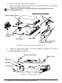
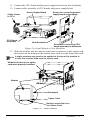
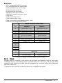
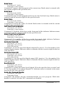
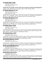
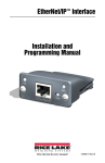
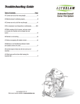
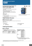
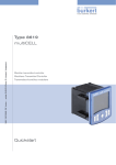
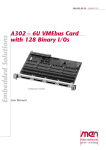
Profibus DP Interface
Interface for 880 Indicator
Installation and
Programming Manual
156784
Contents
About This Manual ................................................................................ 1
1.0
Introduction............................................................................... 1
2.0
Installation ................................................................................ 2
2.1 Installing the Profibus Interface . . . . . . . . . . . . . . . . . . . . . . . . 2
2.2 Profibus LED Status Indicators and Connector. . . . . . . . . . . . 7
3.0
Commands ................................................................................ 9
3.1 Output Data Format . . . . . . . . . . . . . . . . . . . . . . . . . . . . . . . . . 9
3.1.1
BYTE Swapping . . . . . . . . . . . . . . . . . . . . . . . . . . . . . . . . . . 11
3.2 Input Data Format . . . . . . . . . . . . . . . . . . . . . . . . . . . . . . . . . . 11
3.2.1
3.2.2
3.2.3
3.2.4
3.2.5
Command number . . . . . . . . . . . . . . . . . . . . . . . . . . . . . . . .
Status Data . . . . . . . . . . . . . . . . . . . . . . . . . . . . . . . . . . . . . .
Value . . . . . . . . . . . . . . . . . . . . . . . . . . . . . . . . . . . . . . . . . . .
Setting a Float Value: . . . . . . . . . . . . . . . . . . . . . . . . . . . . . . .
Reading a Float Value: . . . . . . . . . . . . . . . . . . . . . . . . . . . . . .
12
12
13
14
14
3.3 Command Descriptions . . . . . . . . . . . . . . . . . . . . . . . . . . . . . 14
4.0
Profibus Interface Specifications........................................... 20
Profibus Interface Limited Warranty .................................................. 21
Technical training seminars are available through Rice Lake Weighing Systems.
Course descriptions and dates can be viewed at www.ricelake.com/training
or obtained by calling 715-234-9171 and asking for the training department.
© Rice Lake Weighing Systems. All rights reserved. Printed in the United States of America.
Specifications subject to change without notice.
Rice Lake Weighing Systems is an ISO 9001 registered company.
Version 1.0
November 12, 2013
Contents
i
Rice Lake continually offers web-based video training on a growing selection
of product-related topics at no cost. Visit www.ricelake.com/webinars.
ii
Profibus Installation and Programming Manual
About This Manual
This manual provides information needed to install and use the Rice Lake Weighing
Systems Profibus®-DP Interface. The Profibus-DP Interface allows indicator to
communicate with a Profibus master device using the Profibus-DP communications
standard.1 See the indicator installation manual for additional installation information
and detailed descriptions of indicator functions.
The Profibus-DP Interface is installed inside the indicator enclosure. Installation in
NEMA 4X stainless steel enclosures permits use in washdown environments.
Some procedures described in this manual require work inside the
WARNING indicator enclosure. These procedures are to be performed by
qualified service personnel only.
Authorized distributors and their employees can view or download this
manual from the Rice Lake Weighing Systems distributor site at
www.rlws.com.
1.0
Introduction
The Profibus-DP Interface functions as a slave node to a Profibus-DP master.
The Interface returns weight and status information from an indicator to a
master device and provides limited control of indicator functions to the
programmer. Indicator configuration and calibration cannot be performed
through the Profibus-DP Interface.
The Profibus-DP master sends commands to the indicator through the
Profibus-DP Interface by writing the commands in the output format. The
Profibus-DP Interface returns the weight and status data in the input format.
These actions are referred to as cyclic I/O. See Section 3.0 for descriptions of
the cyclic I/O commands.
A CD-ROM containing the GSD file used to configure the master device is
supplied with the Profibus-DP Interface.
1.
Profibus® is a registered trademark of Profibus International.
Introduction
1
2.0
Installation
This section describes the procedures used to install the Profibus-DP Interface into
the an indicator.
2.1
Installing the Profibus Interface
J4
J2
J1
PN 156669 Backplate, Controller
PN 153093 Option Card
Also included in kit:
PN 14825 Screw, Mach 4-40NC x 1/4" Qty 4
PN 152358 Module, Profibus
Figure 2-1. Profibus Kit
WARNING Disconnect power before removing indicator backplate.
Use a wrist strap to ground yourself and protect components
CAUTION from electrostatic discharge (ESD) when working inside the
indicator enclosure.
1.
2.
2
Disconnect indicator from power source.
Unplug all connectors from the back of the controller assembly.
Profibus DP Installation and Programming Manual
DIN Rail Clip Bracket
Controller
Assembly
Rotate left and right
clip down away from
the DIN rail.
DIN Hook
Screwdriver Slot
Cable Assembly
Figure 2-2. Remove Controller Assembly
3.
4.
5.
6.
Rotate left and right hooks away from the DIN rail clip.
Carefully remove the controller box from the DIN rail.
Disconnect the display cable harness.
Loosen the four corner screws and carefully pull the backplate straight out
from the enclosure. The boards are still connected to the backplate and will
slide out of the enclosure.
All boards will slide out together, the power supply board and the CPU
Note board are connected by a cable.
Figure 2-3. Remove Backplate With Boards
Installation
3
7.
8.
Remove the cable connecting the boards.
Remove the power board and CPU board from the back plate by loosening
the screws holding them in place.
Retain the screws for installing boards to new backplate. Discard
Note existing backplate.
.
Screws connecting power
supply board to backplate
Power Supply Board
Cable, Power
to CPU
CPU Board
Backplate
Screws connecting CPU
board to backplate
Figure 2-4. Boards Removed from Enclosure
9.
Install the option card on the CPU board standoffs, plugging it into the J8
connector on the CPU board.
10. Secure with option card screws.
Option Card Screw
J8
Connector
Standoff
CPU Board
Figure 2-5. Install Option Card
4
Profibus DP Installation and Programming Manual
Option Card
11. Connect the CPU board and the power supply board to the new backplate.
12. Connect cable assembly to CPU boards and power supply board.
Power Supply Board
Cable, Power
to CPU
CPU Board
Assembly
Screws for connecting power
supply board to backplate
New Backplate
Screws for connecting CPU
board assembly to backplate
Figure 2-6. Install Boards to New Backplate
13. Slide the module into the slot provided until it connects to the option card,
the notches on the bottom of the module must slide over the front of the card.
A slight pressure may need to be applied to the top of the module to
Note ensure the notches slide onto the option card.
Module will connect to option
card when properly installed.
Module
Backplate
Option Card
Notches must slide over
the Option Card.
Figure 2-7. Install Module
Installation
5
14. Once the module is properly seated, tighten the screws on the front to
0.25Nm using a T8 Torx bit (PN 158153, not included), to secure the module
to the option card.
Tighten Screws
Figure 2-8. Secure Module to Option Card
15. Slide backplate with boards into enclosure, ensure that each board is seated
correctly in the grooves of the enclosure.
Ensure the enclosure is in the upright position, otherwise the connector
Note for the display will not align with the front cutcut. The DIN Rail clips will
be at the bottom.
Corner screws
Din Rail Clip
Ensure boards are
seated properly in
the grooves of the
enclosure.
Figure 2-9. Boards Installed in Controller Assembly Enclosure
16. Reassembly control box to the DIN rail.
17. Reconnect all connectors to the back of the controller assembly.
18. Reconnect power to the indicator.
The indicator automatically recognizes all installed option cards when the unit is
powered on. No hardware-specific configuration is required to identify the newlyinstalled card to the system.
6
Profibus DP Installation and Programming Manual
2.2
Profibus LED Status Indicators and Connector
An LED array on the Profibus module provides status information for
troubleshooting.
• LED 1 provides network status;
• LED 2 provides status indication for the Profibus module.
1
2
3
Figure 2-10. Profibus Status LED Module
Operation Mode LED (Item 1)
Status
Off
Steady Green
Flashing Green
Flashing Red (1-flash)
Flashing Red (2-flash)
Description
No powered or not online
Data exchange
Clear
Parametrization error
Profibus configuration error
Module Status LED (Item 2)
Status
Off
Steady Green
Flashing Green
Steady Red
Description
Not initialized
Initialized
Initialized, diagnostic
event(s) present
Exception error
Comments
Anybus state = ‘SETUP¨’ or ‘NW_INIT’
Anybus module has left the ‘NW_INIT’ state
Extended diagnostic bit is set
Anybus state = ‘EXCEPTION’
Installation
7
Connector DB9F (Item 3)
Pin
Signal
1
2
3
4
5
6
7
8
9
Housing
B Line
RTS
GND Bus
+5 V Bus Output
A Line
Cable Shield
8
Description
Positive RxD/TxD, RS485 level
Request to send
ground (isolated)
+5 V termination power (isolated, short-circuit protected)
Negative RxD/TxD, RS485 level
Internally connected to the Anybus protective earth via
cable shield filters according to the PROFIBUS standard.
Profibus DP Installation and Programming Manual
3.0
Commands
Commands are used by the master device to send and receive data from the interface
as integer or floating-point data. The master sends eight bytes in the output format
(used to write commands to the indicator) and reads eight bytes in the input format
(used to read data from the indicator).
Decimal Point Handling
Integer commands return no decimal point information to the master. For example, a
value of 750.1 displayed on the indicator is returned to the master as 7501. Floating
point commands support decimal point information with no special handling.
3.1 Output Data Format
To perform a command, the master uses the output command format to send four 16bit words to the interface. These four words contain the command and any parameters
necessary to execute it. The output command format is shown in Table 3-1.
Word
Description
Word 1
Command number
Word 2
Parameter
Word 3
Value (MSW)
Word 4
Value (LSW)
Table 3-1. Output Data Format
Note See Section 3.1.1 for BYTE swapping parameters.
The contents of each output command format word are described in Table 3-2.
Command number
The number representing the indicator command is sent in the first word. Table 3-2
lists the commands that can be specified for indicators. Some commands may not be
available on all indicators.
A lockout feature that looks for any change in the output format data is
Note incorporated into the indicator receive mechanism to prevent inundation
by the same command (affected commands noted in Table 3-1).
Repeated commands must be separated by any other valid command/
parameter/value combination.
Commands
9
Decimal
Hex
Command
0
1
2
3
9
10
11
12
13
14
16
17
18
19
20
21
22
23
32
33
34
37
38
95
96
97
98
99
112
113
114
115
116
128
253
254
256
268
288
289
290
293
294
0x000
0x001
0x002
0x003
0x009
0x00A
0x00B
0x00C
0x00D
0x00E
0x010
0x011
0x012
0x013
0x014
0x015
0x016
0x017
0x020
0x021
0x022
0x025
0x026
0x05F
0x060
0x061
0x062
0x063
0x070
0x071
0x072
0x073
0x074
0x80
0x0FD
0x0FE
0x100
0x10C
0x120
0x121
0x122
0x125
0x126
Return Status and Weight (integer)
Display Channel
Display Gross Weight
Display Net Weight
Gross/Net key press (toggle)
Zero (see note)
Display Tare (see note)
Enter Tare (see note)
Acquire Tare (see note)
Clear Tare (see note)
Primary Units
Secondary Units
Tertiary Units
Units key press (toggle units)
Print Request
Display Accumulator
Clear Accumulator
Push Weight to Accumulator
Return Gross (integer)
Return Net (integer)
Return Tare (integer)
Return Current Display (integer)
Return Accumulator (integer)
Set Batching State
Batch Start
Batch Pause
Batch Reset
Batch Status
Lock Indicator Front Panel
Unlock Indicator Front Panel
Set Digital Output ON
Set Digital Output OFF
Read Digital I/O Status
Enable Bus Command Handler
No operation
Reset Indicator
Return Status and Weight (float)
Enter Tare (float)
Read Gross (float)
Read Net (float)
Read Tare (float)
Read Current Display (float)
Read Accumulator (float)
Table 3-2. Remote Commands
10 Profibus DP Installation and Programming Manual
Decimal
Hex
304
305
306
307
320
321
322
323
0x130
0x131
0x132
0x133
0x140
0x141
0x142
0x143
Command
Set Setpoint Value (float)
Set Setpoint Hysteresis (float)
Set Setpoint Bandwidth (float)
Set Setpoint Preact (float)
Read Setpoint Value (float)
Read Setpoint Hysteresis (float)
Read Setpoint Bandwidth (float)
Read Setpoint Preact (float)
Table 3-2. Remote Commands (Continued)
Parameter value
To allow communication with a multi-scale indicator, the scale number is sent in the
second word of the output command format. Zero (0) represents the current scale.
Certain commands require a parameter other than a scale number, such as a slot
number, setpoint number, or other selection parameter. See the command descriptions
in Section 3.3 on page 14 for specific command requirements.
Value
The third and fourth words of the output format are used to pass value data on certain
commands. Values entered in these words are treated as unsigned long integers or
floating-point values, depending on the command.
3.1.1
BYTE Swapping
Note See the Ports Menu in the 880 Technical/Service manual (PN 158387)
The 880 indicator sends out and receives data in integer format.
The standard format would be as follows for all input and output values:
High BYTE – Low BYTE
If the Parameter in the 880 FLDBUS/SWAP parameter is set to YES then the BYTE
order changes to:
Low BYTE – High BYTE
Example:
If the weight on the scale reads 10 lbs and a value of 2560 is displayed in your PLC,
either swap the BYTES in your PLC or change the SWAP parameter to YES.
3.2 Input Data Format
In response to a command, the interface returns data and status information to the
master as four 16-bit words. This information is returned in the input command
format shown in Table 3-3.
The value type can be set for those commands that do not specify integer or floating
point data by sending a command 0x000 to specify integer data or command 0x100
for floating-point data. The value type is returned in the status word (bit 14) of the
input format.
Commands 11
Word
Description
Word 1
Word 2
Word 3
Word 4
Command number
Status
Value (MSW)
Value (LSW)
Table 3-3. Input Data Format
Note See Section 3.1.1 for BYTE swapping parameters.
3.2.1
Command number
The first word echoes the command number. If the command fails or is not
recognized, the negative of the command number is returned to signal the error.
3.2.2
Status Data
Indicator status data is returned in the second word (see Table 3-4). Batch commands
return batch status in place of the low byte (see Table 3-5). Setpoint commands return
batch status in the low byte of the status word and the setpoint number in the high
byte.
Word 2
Bit
00
Indicator Status Data
Value=0
Value=1
Error **
No error
(see See “Bit-0 Errors” on
page 13.)
Tare not entered
Tare entered
Not center of zero
Center of zero
Weight invalid
Weight OK
Standstill
In motion
Primary units
Other units
Tare not acquired
Tare acquired
Gross weight
Net weight
Channel number
01
02
03
04
05
06
07
08
09
Note Least significant bit first.
10
11
12
13
Not used
14
Integer data
Floating point data
15
Positive weight
Negative weight
** This error condition does not necessarily mean the weight
being reported is invalid. Refer to the “Weight invalid” bit.
Table 3-4. Indicator Status Data Format
12 Profibus DP Installation and Programming Manual
Bit-0 Errors
• PLC command failed to execute.
• No configuration has taken place.
• Scale parameter is out of range.
• Print error has occurred.
• Load error has occurred.
• Memory error has occurred.
• Analog to digital converter error.
• Tare error.
• Scale over range error.
• Scale under range error.
• Non-recoverable configuration store error.
• Indicator in configuration mode.
Word 2
Bit
00
01
02
03
04
05
06
07
08
09
10
11
12
13
14
15
Batch Function Status Data
Value=0
Value=1
Digital input 4 OFF
Digital input 4 ON
Digital input 3 OFF
Digital input 3 ON
Digital input 2 OFF
Digital input 2 ON
Digital input 1 OFF
Digital input 1 ON
Batch not paused
Batch paused
Batch not running
Batch running
Batch not stopped
Batch stopped
Alarm OFF
Alarm ON
Setpoint number
Integer data
Positive weight
Not used
Floating point data
Negative weight
Table 3-5. Batch Function Status Data Format
3.2.3
Value
Weight data is returned to the master in the third and fourth words of the input
command format, depending on the command and the value type. The weight data
returned is the displayed weight after the command is executed, unless the command
specifies otherwise.
A negative value will be returned in the two’s compliment format.
Commands 13
3.2.4
Setting a Float Value:
Setting a float value in a setpoint requires the value to be sent in two separate integer
values. Most PLCs have a mechanism to take a float value and separate it into to
integer values.
The following is what is needed in the output words to set the value of Setpoint #1 to
10000.
Command word = 304
Parameter word = 1
MSW = 17948
LSW = 16384
3.2.5
Reading a Float Value:
When a float value is read it will be retuned in two integers that will represent the
float value.
The PLC will need to combine MSW and LSW integer values back into a float value.
The following is what is will be returned in the input words if the weight on the scale
is 800.5.
Command Word = 288
Status word = Scale status
MSW= 17480
LSW = 8192
3.3 Command Descriptions
Return Status and Current Weight as Integer
Command: 0, 0x000
Parameter: Scale number
Command 0 returns the status and gross or net scale weight (per scale configuration)
of the specified scale in integer format, without changing the display. This command
also causes the format-independent commands to return a value in the integer format.
Display Channel
Command: 1, 0x001
Parameter: Scale number
Command 1 causes the weight of the specified scale to be displayed and returned in
its current mode and format.
Display Gross Weight
Command: 2, 0x002
Parameter: Scale number
Command 2 causes the gross weight of the specified scale to be displayed and
returned.
Display Net Weight
Command: 3, 0x003
Parameter: Scale number
Command 3 causes the net weight of the specified scale to be displayed and returned.
Gross/Net Key Press (toggle mode)
Command: 9, 0x009
Parameter: Scale number
Command 9 toggles between gross and net mode (and count mode, if enabled). If a
scale number other than 0 is specified, the action will not be seen until the specified
scale is displayed.
Zero
Command: 10, 0x00A
Command 10 performs a ZERO operation on the current scale.
14 Profibus DP Installation and Programming Manual
Display Tare
Command: 11, 0x00B
Parameter: Scale number
Command 11 causes the tare weight on the specified scale to be displayed. If a scale
number other than 0 is specified, the indicator first causes the specified scale to be
displayed. Display returns to the prior mode after checking the indicator.
Enter Tare (integer)
Command: 12, 0x00C
Parameter: Scale number
Value: Tare weight
Command 12 enters a tare for the scale selected. Tare data must be in integer format.
The indicator continues to return weight data in the current mode for the specified
scale.
Acquire Tare (simulate TARE key press)
Command: 13, 0x00D
Parameter: Scale number
Command 13 acquires a tare based on the weight currently on the specified scale. The
indicator continues to return weight data in the current mode for the specified scale.
Clear Tare
Command: 14, 0x00E
Parameter: Scale number
Command 14 clears the tare for the specified scale. The indicator continues to return
weight data in the current mode for the specified scale.
Primary Units
Command: 16, 0x010
Parameter: Scale number
Command 16 switches the current format of the specified scale to the primary units
configured for that scale.
Secondary Units
Command: 17, 0x011
Parameter: Scale number
Command 17 switches the current format of the specified scale to the secondary units
configured for that scale.
Tertiary Units
Command: 18, 0x012
Parameter: Scale number
Command 18 switches the current format of the specified scale to the tertiary units
configured for that scale, if available.
Units Key Press (toggle units)
Command: 19, 0x013
Parameter: Scale number
Command 19 toggles between primary and secondary units of the specified scale.
Print Request
Command: 20, 0x014
Parameter: Scale number
Command 20 causes the indicator to execute a print command for the current scale.
Commands 15
Display Accumulator
Command: 21, 0x015
Parameter: Scale number
Command 21 causes the value of the accumulator for the specified scale to be
displayed and returned. This command is only valid if the accumulator for the
specified scale is enabled.
Clear Accumulator
Command: 22, 0x016
Parameter: Scale number
Command 22 clears the value of the accumulator for the specified scale. This
command is only valid if the accumulator for the specified scale is enabled.
Push Weight to Accumulator
Command: 23, 0x017
Parameter: Scale number
Command 23 adds the net weight on the specified scale to the value of the
accumulator for the specified scale. The scale must return to net zero between
accumulations. The indicator returns the accumulated weight data for the specified
scale. This command is only valid if the accumulator for the specified scale is
enabled.
Return Gross as Integer
Command: 32, 0x020
Parameter: Scale number
Command 32 returns the gross weight value for the specified scale as an integer.
Return Net as Integer
Command: 33, 0x021
Parameter: Scale number
Command 33 returns the net weight value for the specified scale as an integer.
Return Tare as Integer
Command: 34, 0x022
Parameter: Scale number
Command 34 returns the tare weight value for the specified scale as an integer.
Return Current Display as Integer
Command: 37, 0x025
Parameter: Scale number
Command 37 returns the weight value for the specified scale as currently displayed.
This may include gross, net, tare, or accumulator values, as enabled.
Return Accumulator as Integer
Command: 38, 0x026
Parameter: Scale number
Command 38 returns the accumulator value for the specified scale. This command is
only valid if the accumulator for the specified scale is enabled.
Set Batching State
Command: 95, 0x05F
Parameter: State (0 = off; 1 = auto; 2 = manual)
Command 95 sets the batching (BATCHNG) parameter. Indicator status is returned
with the current weight for the last scale specified.
Batch Start
Command: 96, 0x060
Parameter: Scale number
Command 96 starts a batch program from the current step after a stop, pause, or reset.
Batch status is returned with the current weight for the specified scale.
16 Profibus DP Installation and Programming Manual
Batch Pause
Command: 97, 0x061
Parameter: Scale number
Command 97 pauses a batch program at the current step. Batch status is returned with
the current weight for the specified scale.
Batch Reset
Command: 98, 0x062
Parameter: Scale number
Command 98 stops a batch program and resets it to the first batch step. Batch status is
returned with the current weight for the specified scale.
Batch Status
Command: 99, 0x063
Parameter: Scale number
Command 99 returns the status of a batch. Batch status is returned with the current
weight for the specified scale.
Lock Front Panel of Indicator
Command: 112, 0x070
Parameter: Scale number
Command 112 disables all the keys on the front panel of the indicator. Indicator status
is returned with the current weight for the specified scale.
Unlock Front Panel of Indicator
Command: 113, 0x071
Parameter: Scale number
Command 113 re-enables all the keys on the front panel of the indicator. Indicator
status is returned with the current weight for the specified scale.
Set Digital Output ON
Command: 114, 0x072
Parameter: Slot number
Value: Bit number
Command 114 sets the specified digital output ON (active). Use slot number 0 for
onboard digital outputs. Indicator status is returned with the current weight for the last
scale specified.
Set Digital Output OFF
Command: 115, 0x073
Parameter: Slot number
Value: Bit number
Command 115 sets the specified digital output OFF (inactive). Use slot number 0 for
onboard digital outputs. Indicator status is returned with the current weight for the last
scale specified.
Read Digital I/O
Command: 116, 0x074
Parameter: Slot number
Command 116 returns the status for all digital I/O in the specified slot in words 3and
4. Use slot number 0 for onboard digital I/O. Indicator status is returned in the status
area for the last scale specified.
Enable Bus Command Handler
Command: 128, 0x80
Parameter: None
Command 128 enables the bus command handler in a user program. While this
handler is enabled, all other PLC commands are disabled.
Commands 17
No Operation
Command: 253, 0x0FD
Parameter: Scale number
Command 253 provides a command to use between operations, as necessary, without
causing the indicator to perform any action. Indicator status and weight for the
specified scale is returned.
Reset Indicator
Command: 254, 0x0FE
Parameter: None
Command 254 provides a command to remotely reset the indicator. No data is
returned.
Return Status and Current Weight as Float
Command: 256, 0x100
Parameter: Scale number
Command 256 returns the status and weight of the specified scale in floating-point
format, without changing the display. This command also causes the formatindependent commands to return a value in the floating-point format. Returns current
weight at a floating-point format.
Enter Tare as Float
Command: 268, 0x10C
Parameter: Scale number
Value: Tare weight
Command 268 enters a tare for the scale selected in floating-point format. The
indicator returns the tare weight as taken, or 0 for no tare.
Read Gross Weight as Float
Command: 288, 0x120
Parameter: Scale number
Command 288 returns the gross weight value for the specified scale in floating-point
format.
Read Net Weight as Float
Command: 289, 0x121
Parameter: Scale number
Command 289 returns the net weight value for the specified scale in floating-point
format.
Read Tare as Float
Command: 290, 0x122
Parameter: Scale number
Command 290 returns the tare weight value for the specified scale in floating-point
format.
Read Current Display as Float
Command: 293, 0x125
Parameter: Scale number
Command 293 returns the weight value for the specified scale as currently displayed
in floating-point format. This may include gross, net, tare, or accumulator values, as
enabled. The weight value is returned in the mode used to display a scale widget.
Read Accumulator as Float
Command: 294, 0x126
Parameter: Scale number
Command 294 returns the accumulator value for the specified scale in floating-point
format. Batch status is returned in place of the indicator status.
18 Profibus DP Installation and Programming Manual
Set Setpoint Value as Float
Command: 304, 0x130
Parameter: Setpoint number
Value: Setpoint value
Command 320 sets the setpoint value for the specified setpoint in floating-point
format. This command is only valid if the setpoint is configured and requires a
setpoint value. Batch status is returned in place of the indicator status.
Set Setpoint Hysteresis as Float
Command: 305, 0x131
Parameter: Setpoint number
Value: Hysteresis value
Command 305 sets the hysteresis value for the specified setpoint in floating-point
format. This command is only valid if the setpoint is configured and requires a
hysteresis value. Batch status is returned in place of the indicator status.
Set Setpoint Bandwidth as Float
Command: 306, 0x132
Parameter: Setpoint number
Value: Bandwidth value
Command 306 sets the bandwidth value for the specified setpoint in floating-point
format. This command is only valid if the setpoint is configured and requires a
bandwidth value. Batch status is returned in place of the indicator status.
Set Setpoint Preact as Float
Command: 307, 0x133
Parameter: Setpoint number
Value: Preact value
Command 307 sets the preact value for the specified setpoint in floating-point format.
This command is only valid if the setpoint is configured and requires a preact value.
Batch status is returned in place of the indicator status.
Read Setpoint Value as Float
Command: 320, 0x140
Parameter: Setpoint number
Command 320 returns the target value for the specified setpoint in floating-point
format. This command is only valid if the setpoint is configured and requires a target
value. Batch status is returned in place of the indicator status.
Read Setpoint Hysteresis as Float
Command: 321, 0x141
Parameter: Setpoint number
Command 321 returns the hysteresis value for the specified setpoint in floating-point
format. This command is only valid if the setpoint is configured and requires a
hysteresis value. Batch status is returned in place of the indicator status.
Read Setpoint Bandwidth as Float
Command: 322, 0x142
Parameter: Setpoint number
Command 322 returns the bandwidth value for the specified setpoint in floating-point
format. This command is only valid if the setpoint is configured and requires a
bandwidth value. Batch status is returned in place of the indicator status.
Read Setpoint Preact as Float
Command: 323, 0x143
Parameter: Setpoint number
Command 323 returns the preact value for the specified setpoint in floating-point
format. This command is only valid if the setpoint is configured and requires a preact
value. Batch status is returned in place of the indicator status.
Commands 19
4.0
Profibus Interface Specifications
Power Requirements
Bus Adapter Card with Profibus Module, DC Power:
Supply voltage: 6 VDC
Typical current draw: 100 mA
Maximum current draw: 300 mA
Typical power consumption: 0.6 W
Maximum power consumption: 1.8 W
Communications Specifications
Up to 12 Mbit/s
Environmental Specifications
Temperature:
–10° to +40° C (14° to 104° F)
20 Profibus Installation and Programming Manual
Profibus Interface Limited Warranty
Rice Lake Weighing Systems (RLWS) warrants that all RLWS equipment and
systems properly installed by a Distributor or Original Equipment Manufacturer
(OEM) will operate per written specifications as confirmed by the Distributor/OEM
and accepted by RLWS. All systems and components are warranted against defects in
materials and workmanship for one year.
RLWS warrants that the equipment sold hereunder will conform to the current written
specifications authorized by RLWS. RLWS warrants the equipment against faulty
workmanship and defective materials. If any equipment fails to conform to these
warranties, RLWS will, at its option, repair or replace such goods returned within the
warranty period subject to the following conditions:
• Upon discovery by Buyer of such nonconformity, RLWS will be given prompt
written notice with a detailed explanation of the alleged deficiencies.
• Individual electronic components returned to RLWS for warranty purposes must
be packaged to prevent electrostatic discharge (ESD) damage in shipment.
Packaging requirements are listed in a publication, “Protecting Your Components
From Static Damage in Shipment,” available from RLWS Equipment Return
Department.
• Examination of such equipment by RLWS confirms that the nonconformity
actually exists, and was not caused by accident, misuse, neglect, alteration,
improper installation, improper repair or improper testing; RLWS shall be the sole
judge of all alleged non-conformities.
• Such equipment has not been modified, altered, or changed by any person other
than RLWS or its duly authorized repair agents.
• RLWS will have a reasonable time to repair or replace the defective equipment.
Buyer is responsible for shipping charges both ways.
• In no event will RLWS be responsible for travel time or on-location repairs,
including assembly or disassembly of equipment, nor will RLWS be liable for the
cost of any repairs made by others.
THESE WARRANTIES EXCLUDE ALL OTHER WARRANTIES, EXPRESSED OR IMPLIED,
INCLUDING WITHOUT LIMITATION WARRANTIES OF MERCHANTABILITY OR
FITNESS FOR A PARTICULAR PURPOSE. NEITHER RLWS NOR DISTRIBUTOR WILL,
IN ANY EVENT, BE LIABLE FOR INCIDENTAL OR CONSEQUENTIAL DAMAGES.
RLWS AND BUYER AGREE THAT RLWS’ SOLE AND EXCLUSIVE LIABILITY
HEREUNDER IS LIMITED TO REPAIR OR REPLACEMENT OF SUCH GOODS . I N
ACCEPTING THIS WARRANTY, THE BUYER WAIVES ANY AND ALL OTHER CLAIMS
TO WARRANTY.
SHOULD THE SELLER BE OTHER THAN RLWS, THE BUYER AGREES TO LOOK ONLY
TO THE SELLER FOR WARRANTY CLAIMS.
N O TERMS , CONDITIONS, UNDERSTANDING, OR AGREEMENTS PURPORTING TO
MODIFY THE TERMS OF THIS WARRANTY SHALL HAVE ANY LEGAL EFFECT UNLESS
MADE IN WRITING AND SIGNED BY A CORPORATE OFFICER OF RLWS AND THE
BUYER.
© Rice Lake Weighing Systems, Inc. Rice Lake, WI USA. All Rights Reserved.
RICE LAKE WEIGHING SYSTEMS • 230 WEST COLEMAN STREET • RICE LAKE, WISCONSIN
54868 • USA
Profibus Interface Specifications 21
Notes
22 Profibus Installation and Programming Manual
230 W. Coleman St. t Rice Lake, WI 54868 t USA
U.S. 800-472-6703 t Canada/Mexico 800-321-6703 t International 715-234-9171 t Europe +31 (0) 88 2349171
www.ricelake.com www.ricelake.mx www.ricelake.eu www.ricelake.co.in m.ricelake.com
© Rice Lake Weighing Systems
PN 156784
11/2013