1
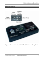
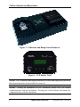
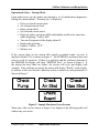
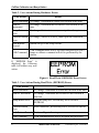
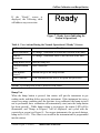
CALPLUS
™
CALIBRATION AND BUMP STATION
for the GasBadge® Product Line of
Hand-held Single-gas Monitoring Systems
Operation • Troubleshooting
Part Number:
17122565
Version Number: 1.0
Release Date:
August 23, 2005
For foreign language versions of
this manual, go to www.indsci.com.
CalPlus Calibration and Bump Station
Table of Contents
Hardware Overview ...................................................................................................3
Warnings and Cautionary Statements........................................................................4
Unpacking the Instrument..........................................................................................4
General Operation ......................................................................................................5
Introduction ........................................................................................................5
Calibration and Bump Station Hardware ...........................................................5
Operational States – Startup Mode ....................................................................7
Bump Test ..........................................................................................................9
Calibration ........................................................................................................12
Operational States – USB Connection .............................................................15
Printer Interface................................................................................................16
USB Communications Interface ......................................................................18
Electric Eye Operation .....................................................................................18
Manual Setup of the Station .............................................................................20
Print Events ......................................................................................................22
Print Buffer.......................................................................................................24
Clear Buffer......................................................................................................26
Setting Next Cal Day (Cal Days 30) ................................................................27
Set Date ............................................................................................................28
Select Language ...............................................................................................30
System Check ...................................................................................................31
Exit ...................................................................................................................32
Install the DataLink Admin Console (DAC) on the PC ..........................................33
Using the PC Software.............................................................................................34
Trouble Shooting......................................................................................................42
Performance Specifications .....................................................................................43
2
INDUSTRIAL SCIENTIFIC
Version 0.8 (p/n: 17122565)
CalPlus Calibration and Bump Station
Hardware Overview
Figure 1. Hardware Overview of the CalPlus Calibration and Bump Station
Version 0.8 (p/n: 17122565)
INDUSTRIAL SCIENTIFIC
3
CalPlus Calibration and Bump Station
Warnings and Cautionary Statements
WARNING: Read and understand this manual before operating.
CAUTION: For safety reasons, this equipment must be operated and
serviced by qualified personnel only.
WARNING: Failure to perform certain procedures or note certain
conditions may impair the performance of this product. For maximum
safety and optimal performance, please read and follow the procedures and
conditions listed below.
• Never cover or insert foreign objects into the alarm signal opening. The
opening must remain clear and free of foreign objects, otherwise any
alerts made during an alarm state may not be heard or identified.
• Contact your service representative immediately if you suspect that the
GasBadge Plus is working abnormally.
Unpacking the Instrument
The table below lists components and part numbers of accessories and peripheral
equipment used with the CalPlus Calibration and Bump Station.
Table 1. CalPlus Components
4
Quantity
Part Number
Description
1
1816344-xx
1
17122565
User Manual
1
17093659
Urethane tubing (4 feet)
1
17121310
USB cable
1
17118027
Fitting (for gas inlet)
1
17124074
Fitting (for fresh air cylinder)
1
17121070
DataLink Accessory Software CD
1
17051710
Power Cord (North America)
1
17118118
Power Supply
CalPlus Calibration Station
INDUSTRIAL SCIENTIFIC
Version 0.8 (p/n: 17122565)
CalPlus Calibration and Bump Station
General Operation
Introduction
The CalPlus is a stand-alone calibration station designed to work in conjunction
with the GasBadge Plus Personal Single Gas Monitor. The calibration station
performs bump test and calibrations of the instrument. The station saves the test
results and can send them to an external serial printer (via RS-232 connection), an
internal printer (optional), or to a PC via a USB interface.
Calibration and Bump Station Hardware
The calibration station’s interface with the user is comprised of:
•
•
•
•
character LCD display
two pushbuttons
three LEDs
physical connection point for the instrument.
The eight-character by two-line LCD
display shows the status of the calibration
station. The LCD display has a softwarecontrolled backlight that is enabled when
the station is performing a task.
The two calibration station pushbuttons:
• Bump button
• Calibrate button.
Figure 2. Sample LCD Display
These buttons are used to initiate a bump test or a calibration on the installed
instrument. In addition, they can be used to navigate through the setup screens for
the calibration station. Most of the navigation is controlled by “simple” button
pushes.
NOTE: Setup mode is only accessible by holding both of the buttons for an
extended period of time.
Three software-controller LEDs show the status of the installed instrument:
•
•
•
•
Green
Amber
Red
No LED
Calibration or bump test passed
Calibration or bump test in progress (or charging)
Calibration or bump test failed
Station “Ready” with no buttons pressed.
Version 0.8 (p/n: 17122565)
INDUSTRIAL SCIENTIFIC
5
CalPlus Calibration and Bump Station
Figure 3. Calibration and Bump Station Hardware
Figure 4. LCD Display Panel
NOTE: The Calibration and Bump Station has a switch that signals the processor
that an instrument has been installed or removed.
NOTE: Placing an instrument on the calibration station does not initiate
communications with the instrument. Pressing one of the buttons will initiate the
communications with the instrument.
6
INDUSTRIAL SCIENTIFIC
Version 0.8 (p/n: 17122565)
CalPlus Calibration and Bump Station
Operational States – Startup Mode
Upon initial power up, the station runs through a set of initialization diagnostics.
During the current checks, “Warming Up” is displayed.
•
•
•
•
•
•
•
•
•
Power on, board current check
Air solenoid current check
Pump current check
Gas solenoid current check
Flash red, amber, and green LEDs individually and all at the same time,
while displaying “Verify LEDs”
Turn on all segments of the display, then off.
Display date and time
Display “CalPlus vX.X”
Memory test.
If the current draw by the station falls outside acceptable limits, an error is
displayed on the LCD, as shown in Figure 5. The EEPROM is written to/then read
from to verify its operation. If there is a problem with the read/write function of
the EEPROM, the display will show “EEPROM Error”, as shown in Figure 6. If
the station has more than one failure, the screens will cycle and display each
anomaly. If no problems are noted, the station will display “Ready” on the display
to indicate to the user that the calibration station is turned on, and operational, as
shown in Figure 7.
Figure 5. Sample Hardware Error Screens
When any of the screens shown in Figure 5 are displayed, the following table will
address any user action.
Version 0.8 (p/n: 17122565)
INDUSTRIAL SCIENTIFIC
7
CalPlus Calibration and Bump Station
Table 2. User Actions During Hardware Errors
User Action
Result
Insert Instrument No change. Instrument in station not checked at this time.
Remove
Instrument
No change. Instrument not in station is not checked at this
time.
Bump Button
Press
No change. Station is in error, cannot perform bump test.
Calibrate Button
Press
No change. Station is in error, cannot perform calibration.
Both Buttons
Pressed
Station will go to the setup screens.
USB Command
USB communications will be accepted and processed, but a
bump or calibrate command will not be performed by the
station.
If “EEPROM Error” is
displayed, the following
table will address any user
action.
Figure 6. Read/Write (EEPROM) Error Screen
Table 3. User Actions During Read/Write (EEPROM) Errors
User Action
Result
Insert Instrument
No change. Instrument in station not checked at this time.
Remove Instrument
No change. Instrument not in station is not checked at
this time.
Bump Button Press
Start the bump test. Record may not be saved to
EEPROM.
Calibrate Button
Press
Start calibration. Record may not be saved to EEPROM.
Both Buttons Pressed
Station will go to the setup screens.
USB Command
USB communications will be accepted and processed.
8
INDUSTRIAL SCIENTIFIC
Version 0.8 (p/n: 17122565)
CalPlus Calibration and Bump Station
If the “Ready” screen is
displayed, the following table
will address any user action.
Figure 7. Ready Screen Indicating the
Station is Operational
Table 4. User Actions During the Normal Operational (“Ready”) Screen
User Action
Result
Insert Instrument
No change. Instrument in station not checked at this time.
Remove
Instrument
No change. Instrument status is not checked at this time.
Bump Button Press Start the bump test
Calibrate Button
Press
Start calibration.
Both Buttons
Pressed
Station will go to the setup screens.
USB Command
USB communications will be accepted and processed.
NOTE: Cycle the power of the CalPlus to clear errors.
Bump Test
When the bump button is pressed, that station will put the instrument in gas
reading mode, and then deliver gas to the instrument. If the instrument has seen a
sensor over-range condition since the last time it was calibrated, the bump test will
not be performed, but a calibration will automatically start (once the bump button
has been pressed). While bump testing is in progress, the amber LED will be
illuminated, and “Bump in Progress” will be displayed, and cycled with the
expected gas screen (see Figure 8). For oxygen instruments, the gas used during a
bump test is 19.0%. This value is not stored in the instrument and is programmed
into the station.
Version 0.8 (p/n: 17122565)
INDUSTRIAL SCIENTIFIC
9
CalPlus Calibration and Bump Station
Figure 8. Bump Test and Gas Type/Concentration Screens
When the bump test is complete, the station will send a bump test report to the
printer (via the RS232 port) and save a copy in memory. If an instrument fails
bump testing, the red LED will be illuminated, and the display will show “Bump
Fail” (Figure 9). The instrument will automatically be calibrated, if it fails the
bump test (10-second time-out that will display “Bump Fail”, and then a
calibration will be automatically started). The failed bump test report will still be
printed and saved. If the instrument passes the bump test, the green LED will be
illuminated and “Bump Pass” will be displayed (Figure 10). These screens will be
displayed until the user removes the instrument from the station.
If the “Bump in Progress” or the gas type and concentration screen is displayed,
the following table will address any user action.
Table 5.
User Actions During Bump Test and Gas Type/Concentration
Screens
User Action
Result
Insert Instrument
Not Available. Instrument must already be inserted to get to
this screen.
Remove
Instrument
Station will abort the bump test and turn off the gas, and
return to the “Ready” state (see Figure 7)
Bump Button
Press
Bump button press is ignored by station.
Calibrate Button
Press
Calibrate button press is ignored by the station.
Both Buttons
Pressed
Both buttons pressed is ignored by the station.
USB Command
USB commands are ignored by the station.
10
INDUSTRIAL SCIENTIFIC
Version 0.8 (p/n: 17122565)
CalPlus Calibration and Bump Station
Figure 9. Bump Test Failure Screen
Figure 10. Bump Test Passed Screen
If the “Bump Fail” screen is displayed, the following table will address any user
action.
Table 6. User Actions During Bump Test Failure Screen
User Action
Result
Insert
Instrument
Not available. Instrument must already be inserted to get to
this screen.
Remove
Instrument
Station will return to the “Ready” screen and state (Figure 7).
All LEDs will turn off.
Bump Button
Press
Bump test is started, if button press within 10 seconds of
“Bump Fail” displayed.
Calibrate
Button Press
Station will start the calibration.
Both Buttons
Pressed
Station will enter the setup mode.
USB Command
USB commands will be processed by the station.
Version 0.8 (p/n: 17122565)
INDUSTRIAL SCIENTIFIC
11
CalPlus Calibration and Bump Station
If the “Bump Pass” screen is displayed, the following table will address any user
action.
Table 7. User Actions During Bump Test Passed Screen
User Action
Result
Insert Instrument
Not available. Instrument must already be inserted to get to
this screen.
Remove
Instrument
Station will return to the “Ready” screen and state. All LEDs
will turn off.
Bump Button
Press
Bump test is started.
Calibrate Button
Press
If calibration has passed, station will go to the “Cal Again?”
screen in Figure 11. If calibration has failed, calibration will
start on the button press.
Both Buttons
Pressed
Station will enter the setup mode.
USB Command
USB commands will be processed by the station.
Calibration
When the calibration button is pressed, the station will perform an interrogation to
determine if the instrument has been calibrated previously. If the instrument has
NOT been calibrated previously, the station will first zero the instrument (if it has a
Toxic sensor) and then calibrate it. If the instrument is oxygen, the zeroing is not
done, and the station will initiate the calibration sequence.
If the instrument has been calibrated,
“Cal Again?” will be displayed, as
shown in Figure 11. If the user presses
the calibrate button again, the instrument
will be calibrated. If the instrument is
removed, or no calibrate button press is
noted within a short period of time
(seconds), the instrument is NOT
calibrated again.
Figure 11. Calibrate Again Screen
If the “Cal Again?” screen is displayed, the following table will address any user
action.
12
INDUSTRIAL SCIENTIFIC
Version 0.8 (p/n: 17122565)
CalPlus Calibration and Bump Station
Table 8. User Actions During the Cal Again Screen
User Action
Result
Insert Instrument
Not available. Instrument must already be inserted to get to
this screen.
Remove
Instrument
Station will go to “Ready.”
Bump Button Press Bump button press is ignored by station.
Calibrate Button
Press
Start calibration.
Both Buttons
Pressed
Both buttons pressed is ignored by the station.
USB Command
USB commands are ignored by the station.
While zeroing and calibrating, the amber
LED is illuminated. When zeroing, the
display shows “Zero in Progress”, as
shown in Figure 12. When the instrument
is calibrating, “Cal in Progress” will be
displayed as well as the gas concentration
expected. The two screens will be cycled,
as shown in Figure 13. Then, when the
calibration is complete, the calibration
report will be sent out the printer port, and
saved in memory.
Figure 12. Zeroing Screen
If an instrument fails either zero or calibration, the red LED will be illuminated,
and “Cal Fail” will be displayed (see Figure 14). If the instrument passes
calibration, the green LED will be illuminated, and “Cal Pass” will be displayed
(see Figure 14). These pass/fail screens will be displayed until the user removes
the instrument from the station. If the until fails a zero or a calibration, the
instrument will be unusable until a good zero and calibration are performed on the
instrument.
If the “Zero in Progress” screen is displayed, the following table will address any
user action.
Version 0.8 (p/n: 17122565)
INDUSTRIAL SCIENTIFIC
13
CalPlus Calibration and Bump Station
Table 9. User Actions During the Zero In Progress Screen
User Action
Result
Insert Instrument
Not available. Instrument must already be inserted to get
to this screen.
Remove Instrument
Station will abort the zeroing and calibration.
Bump Button Press
Bump button press is ignored by station.
Calibrate Button
Press
Calibrate button press is ignored by the station.
Both Buttons
Pressed
Both buttons pressed is ignored by the station.
USB Command
USB commands are ignored by the station.
Figure 13. Calibration Test and Gas Type/Concentration Screens
If the “Cal in Progress” or the gas type and concentration screen is displayed, the
following table will address any user action.
Table 10. User Actions During Cal In Progress or Gas Type/Concentration
Screens
User Action
Result
Insert Instrument
Not available. Instrument must already be inserted to
get to this screen.
Remove Instrument
Station will abort the calibration and turn off the gas.
Bump Button Press
Bump button press is ignored by station.
Calibrate Button Press
Calibrate button press is ignored by the station.
Both Buttons Pressed
Both buttons pressed is ignored by the station.
USB Command
USB commands are ignored by the station.
14
INDUSTRIAL SCIENTIFIC
Version 0.8 (p/n: 17122565)
CalPlus Calibration and Bump Station
Figure 14. Calibration Pass and Fail Screens
If the “Cal Pass” or “Cal Fail” screen is displayed, the following table will address
any user action.
Table 11. User Actions During Calibration Pass or Fail Screens
User Action
Result
Insert
Instrument
Not available. Instrument must already be inserted to get to
this screen.
Remove
Instrument
Station will return to the “Ready” screen and state (Figure 7).
All LEDs will turn off.
Bump Button
Press
If calibration has passed, bump test is started. If calibration
failed, calibration is started.
Calibrate
Button Press
If calibration has passed, station will go to the “Cal Again?”
screen in Figure 11. If calibration has failed, calibration will
start on the button press.
Both Buttons
Pressed
Station will enter the setup mode.
USB Command
USB commands will be processed by the station.
If the instrument has seen a sensor over-range condition since the last time it was
calibrated, the calibration is done as soon as the button is pressed.
Operational States – USB Connection
If the host PC is downloading calibration and bump test reports from the
instrument, or from the station, and a button is pressed during the USB process,
“Busy Wait” will be shown on the display (Figure 15) for a short period of time,
then go back to the screen that was displayed.
Version 0.8 (p/n: 17122565)
INDUSTRIAL SCIENTIFIC
15
CalPlus Calibration and Bump Station
When the download of information is
complete, the station will show the
“Ready” screen again and the buttons will
be available.
If the “Busy Wait” screen is displayed,
the following table will address any user
action.
Figure 15. Busy Wait Screen
Table 12. User Actions During the Busy Wait Screen
User Action
Result
Insert
Instrument
If downloading from instrument, instrument is already inserted.
If downloading from station, instrument not checked (not
available).
Remove
Instrument
If downloading from the instrument, download is aborted.
Station will return to the “Ready” screen and state. All LEDs
will turn off. If downloading from the station (not available).
Bump Button
Press
Bump button press is ignored by the station during the actual
communication, but will start a bump if between commands.
Download is aborted.
Calibrate
Button Press
Calibrate button press is ignored by the station during the
actual communication, but will start a calibration if between
commands. Download is aborted.
Both Buttons
Pressed
Both buttons pressed is ignored by the station during the actual
communication, but will enter Setup if between commands.
Download is aborted.
USB
Command
USB commands are being processed at this time.
Printer Interface
The Calibration and Bump Station interfaces to a printer through an RS232
connection. If the calibration station has an internal printer connected and an
RS232 printer connected, the external printer will have precedence, i.e., the records
will be printed to the external printer. If the temperature inside the CalPlus is less
than -10 °C, the internal printer will be shut off due to the excessive current draw.
“PRN OFF/LOW TEMP” will be displayed.
16
INDUSTRIAL SCIENTIFIC
Version 0.8 (p/n: 17122565)
CalPlus Calibration and Bump Station
If the station tries to print and the printer status
is fault (out of paper, paper jam, etc.), nothing
will be printed and the printer’s LEDs will
indicate the problem. Note that the internal
printer does not respond to inquiries.
Figure 16. No Comm Printer
Error Screen
After a calibration is completed, the station and printer will produce a process
record with the format shown in Figure 17.
Industrial Scientific Corp.
Cal Plus
v1.0.0
25 Dec 04
Time: 14:45
Gas Badge (or Gas Badge Pro)
Serial Number: 1234567890
Software v1.0
Hardware v2.0
Bay Number 1 (for multiple bay version)
Zero: PASS
Calibration: PASS
Sensor: CO
Span Reserve: 110 ppm
Cal Gas Conc.: 100 ppm
High Alarm: 70 ppm
Low Alarm: 35 ppm
Next Cal Due: 24 Jan 05
Cylinder Lot No.:
_____________________________
Technician Initials:
_____________________________
________________________________________
Figure 17. Sample Calibration Process Record
Version 0.8 (p/n: 17122565)
INDUSTRIAL SCIENTIFIC
17
CalPlus Calibration and Bump Station
After a bump process is completed, the station and printer will produce a process
record as shown in Figure 18.
Industrial Scientific Corp.
Cal Plus
v1.0.0
25 Dec 04
Time: 14:45
Gas Badge (or Gas Badge Pro)
Serial Number: 1234567890
Software v1.0
Hardware v2.0
Bay Number 1 (for multiple bay version)
Bump Test:
PASS
Sensor: CO
Gas Reading: 61 ppm
Cal Gas Conc.: 100 ppm
High Alarm: 70 ppm
Low Alarm: 35 ppm
Cylinder Lot No.:
_____________________________
Technician Initials:
_____________________________
________________________________________
Figure 18. Sample Bump Process Record
USB Communications Interface
The station can communicate with a host PC across a USB connection. The host
PC can be running the Data Link software. The following capabilities are included
in the calibration station, with respect to commands from either of the Host PC
software:
• download reports from the instrument
• download event log from the instrument.
Electric Eye Operation
The station will be able to detect if an instrument is installed by use of an
electronic eye. If the electronic eye indicates an instrument is present, and the user
presses a button to initiate a calibration or a bump, and the instrument does not
respond, “Inst Comm Err” will be displayed, as shown in Figure 19.
18
INDUSTRIAL SCIENTIFIC
Version 0.8 (p/n: 17122565)
CalPlus Calibration and Bump Station
If the user presses a button, and the electronic eye does not detect an instrument,
“No Inst Detected” will be displayed, as shown in Figure 20.
Figure 19. Instrument
Communications Error Screen
Figure 20. No Instrument Detected
Screen
If the “Inst Comm Err” screen is displayed, the following table will address any
user action.
Table 13. User Actions During Instrument Communications Error Screen
User Action
Result
Insert Instrument Instrument should be installed to get this screen.
Remove
Instrument
Station goes back to “Ready” state and screen (see Figure 7).
Bump Button
Press
Station will try to communicate with instrument, if not
possible, screen stays. If instrument does communicate, go to
bump test.
Calibrate Button
Press
Station will try to communicate with instrument, if not
possible, screen stays. If instrument does communicate, go to
calibration.
Both Buttons
Pressed
Station will go to the setup screens.
USB Command
USB communications will be accepted and processed.
Version 0.8 (p/n: 17122565)
INDUSTRIAL SCIENTIFIC
19
CalPlus Calibration and Bump Station
If the “No Inst Detected” screen is displayed, the following table will address any
user action.
Table 14. User Actions During No Instrument Detected Error Screen
User Action
Result
Insert Instrument Instrument should NOT be installed to get this screen.
Remove
Instrument
Station goes back to “Ready” state and screen (see Figure 7).
Bump Button
Press
Station will check for an instrument, if not there, screen stays.
If instrument is detected, go to bump test.
Calibrate Button
Press
Station will check for an instrument, if not there, screen stays.
If instrument is detected, go to calibration.
Both Buttons
Pressed
Station will go to the setup screens.
USB Command
USB communications will be accepted and processed.
Manual Setup of the Station
The station will be able to be setup using the LCD, the calibrate button, and the
bump button. Once the station is configured and running, pressing and holding
both the calibrate button and the bump button for 3-5 seconds will take the user to
the setup mode. Figure 21 shows the screens to be displayed, with “Print Events”
as the starting point. Pressing the bump button will scroll to the next screen. Each
screen is explained in the sections that follow.
20
INDUSTRIAL SCIENTIFIC
Version 0.8 (p/n: 17122565)
CalPlus Calibration and Bump Station
Figure 21. Setup Mode Flowchart
If any of the screens in Figure 21 are displayed, the following table will address
any user action.
Table 15. User Actions During Setup Mode Screens
User Action
Result
Insert Instrument
Not available. Does not matter if instrument inserted.
Remove Instrument
Not available. Does not matter if instrument not there.
Bump Button Press
Station goes to the next screen.
Calibrate Button
Press
Station goes to the displayed screen’s sub-screen (details
in sub-screen section).
Both Buttons
Pressed
Both buttons pressed is ignored by the station.
USB Command
USB communications will be ignored.
Pressing the calibrate button will select the feature shown on the display.
Version 0.8 (p/n: 17122565)
INDUSTRIAL SCIENTIFIC
21
CalPlus Calibration and Bump Station
Print Events
If the calibrate button is pressed while
the “Print Events” screen is displayed,
the “Print OK” screen is shown,
verifying the user’s selection to
download and print the saved data from
the instrument. Instrument must be
installed to print the events from it.
If the user presses the bump button, No
is selected, and the user is returned to
the “Print Events” screen.
If the user presses calibrate, Yes is
selected, the data is downloaded and
sent to the printer port, and “Printing
Events” is displayed. When the printing
is finished, the “Print Buffer” screen is
displayed.
If “Print Events”, “Print OK”, or
“Printing Events” is displayed, the
following table will address any user
actions.
Figure 22. Print Events Screens
22
INDUSTRIAL SCIENTIFIC
Version 0.8 (p/n: 17122565)
CalPlus Calibration and Bump Station
Table 16. User Actions During the Print Events, Print OK, and Printing
Events Screens
User Action
Print Events
Results
Print OK
Results
Printing Events
Results
Insert
Instrument
Not available.
Does not matter if
instrument
inserted.
Not available. Does
not matter if
instrument inserted.
Not available. Does
not matter if
instrument inserted.
Remove
Instrument
Not available.
Does not matter if
instrument not
there.
Not available. Does
not matter if
instrument not there.
Not available. Does
not matter if
instrument not
there.
Bump Button
Press
No is selected and
Station goes to the
station returns to
“Print OK” screen.
“Print Buffer”.
Button press is
ignored by the
station.
Calibrate
Button Press
Yes is selected and
Station goes to the station prints the
“Print Buffer”
events and goes to
screen.
“Printing Events”
screen.
Button press is
ignored by the
station.
Both Buttons
Pressed
Both buttons
pressed is ignored
by the station.
Both buttons pressed
is ignored by the
station.
Both buttons
pressed is ignored
by the station.
USB
Command
USB
communications
will be ignored.
USB
USB communications
communications
will be ignored.
will be ignored.
Version 0.8 (p/n: 17122565)
INDUSTRIAL SCIENTIFIC
23
CalPlus Calibration and Bump Station
Print Buffer
If the calibrate button is pressed while the
“Print Buffer” screen is displayed, the
“Print OK” screen is shown, verifying the
user’s selection to print every saved bump
and cal report.
If the user presses the bump button, No is
selected, and the user is returned to the
“Print Buffer” screen.
If the user presses calibrate, Yes is selected,
and every saved bump and cal report is sent
to the printer port, and “Printing” is
displayed. The buffer is NOT erased.
When the printing is finished, the “Clear
Buffer” screen is displayed.
The buffer can hold up to 200 records then
will over-write. If the buffer is full, it will
take up to an hour to print the entire
contents.
If “Print Buffer”, “Print OK”, or
“Printing…” is displayed, the following
table will address any user actions.
If “Print Buffer” is displayed, the following
table will address any user action.
24
Figure 23. Print Buffer Screens
INDUSTRIAL SCIENTIFIC
Version 0.8 (p/n: 17122565)
CalPlus Calibration and Bump Station
Table 17. User Actions During the Print Buffer, Print OK, and Printing…
Screens
User
Action
Print Buffer
Results
Print OK
Results
Printing…
Results
Insert
Instrument
Not available. Does Not available. Does
not matter if
not matter if
instrument inserted. instrument inserted.
Not available. Does
not matter if
instrument inserted.
Remove
Instrument
Not available. Does
Not available. Does
not matter if
not matter if
instrument not
instrument not there.
there.
Not available. Does
not matter if
instrument not
there.
Bump
Button
Press
Station goes to the
“Clear Buffer”
screen.
No is selected and
Button press is
station returns to
ignored by the
“Print Buffer” screen. station.
Calibrate
Button
Press
Station goes to the
“Print OK” screen.
Yes is selected and
station prints the
buffer and goes to
“Printing” screen.
Button press is
ignored by the
station.
Both
Buttons
Pressed
Both buttons
pressed is ignored
by the station.
Both buttons pressed
is ignored by the
station.
Both buttons
pressed is ignored
by the station.
USB
Command
USB
communications
will be ignored.
USB
USB communications
communications
will be ignored.
will be ignored.
Version 0.8 (p/n: 17122565)
INDUSTRIAL SCIENTIFIC
25
CalPlus Calibration and Bump Station
Clear Buffer
If the calibrate button is pressed while the
“Clear Buffer” screen is displayed, the
“Clear OK” screen is shown, verifying the
user’s selection to clear every saved bump
and cal report.
If the user presses the bump button, No is
selected, and the user is returned to the
“Clear Buffer” screen.
If the user presses calibrate, Yes is selected,
every saved bump and cal report is cleared,
and the “Cal Days” screen is displayed.
If “Clear Buffer” or “Clear OK” is
displayed, the following table will address
any user actions.
Figure 24. Clear Buffer Screens
Table 18. User Actions During the Clear Buffer and Clear OK Screens
User Action
Clear Buffer Results
Clear OK Results
Insert
Instrument
Not available. Does not
Not available. Does not matter if
matter if instrument inserted. instrument inserted.
Remove
Instrument
Not available. Does not
matter if instrument not
there.
Not available. Does not matter if
instrument not there.
Bump Button
Press
Station goes to the “Cal
Days” screen.
No is selected and station returns
to “Clear Buffer” screen.
Calibrate
Button Press
Station goes to the “Clear
OK” screen.
Yes is selected and station clears
the buffer and goes to “Cal Days”
screen.
Both Buttons
Pressed
Both buttons pressed is
ignored by the station
Both buttons pressed is ignored
by the station.
USB
Command
USB communications will
be ignored.
USB communications will be
ignored.
26
INDUSTRIAL SCIENTIFIC
Version 0.8 (p/n: 17122565)
CalPlus Calibration and Bump Station
Setting Next Cal Day (Cal Days 30)
If the calibrate button is pressed while the “Cal
Days” screen is displayed, the “30 Days” screen
is shown, allowing the user to increase the
number of days until the next calibration by
pressing the bump button. The number 30 will
increase slowly (in increments of 1), then faster
while the bump button is held. The rollover point
is set at 365 days, after which the counter restarts
at 1.
If the user presses calibrate, the new number of
days that is displayed will be saved into memory
and the “Set Date” screen is displayed.
If “Cal Days” or “30” is displayed, the following
table will address any user actions.
Figure 25. Cal Days Screens
Table 19. User Actions During Cal Days or 30 Screens
User Action
Cal Days Results
“30” Screen Results
Insert
Instrument
Not available. Does not
matter if instrument
inserted.
Not available. Does not matter if
instrument inserted.
Remove
Instrument
Not available. Does not
matter if instrument not
there.
Not available. Does not matter if
instrument not there.
Bump Button
Press
Station goes to the “Set
Date” screen.
Station will increment the days until
next cal by one for each press until
365 is reached, then the counter
starts back at 1.
Calibrate
Button Press
Station goes to the “30”
screen.
Station saves the number displayed
into memory.
Both Buttons
Pressed
Both buttons pressed is
ignored by the station.
Both buttons pressed is ignored by
the station.
USB
Command
USB communications will USB communications will be
be ignored.
ignored.
Version 0.8 (p/n: 17122565)
INDUSTRIAL SCIENTIFIC
27
CalPlus Calibration and Bump Station
Set Date
If the cal button is pressed while the “Set Date”
screen is displayed, the “01 Month” screen is
displayed, allowing the user to increase the
month to set the correct date. The month
number will increase slowly (in increments of
1). The rollover point is set at 12 months, after
which point the counter restarts at 1.
If the user presses calibrate, the new month
number is saved to the clock and the “01 Day”
screen is displayed. This screen cycles from 1
to 31, and then restarts at 1.
If the user presses calibrate, the new day number
is saved to the clock and the “05 Year” screen is
displayed. The year screen (which displays only
the last two digits of the year) cycles up to 99,
and then restarts at 00.
If the user presses calibrate, the new year
number is saved to the clock and the “12 Hour”
screen is displayed. The clock is set using a 24hour clock. The hours cycle up to 23, and then
restart at 00 by pressing the bump button.
If the user presses calibrate, the new hour
number is saved to the clock and the “00 Min”
screen is displayed. The Min screen cycles up
to 59, and then restarts at 00 by pressing the
bump button.
If the user presses calibrate, the new minutes
number is saved to the clock and the “Select
Language” screen is displayed.
If any of the “Set Date” screens are displayed,
the following table will address any user
actions.
Figure 26. Set Date Screens
28
INDUSTRIAL SCIENTIFIC
Version 0.8 (p/n: 17122565)
CalPlus Calibration and Bump Station
Table 20. User Actions During the Set Date Screens
User
Action
Set Date Results
Month, Day, Year, Hour, Minute
Results
Insert
Instrument
Not available. Does
not matter if
instrument inserted.
Not available. Does not matter if
instrument inserted.
Remove
Instrument
Not available. Does
not matter if
instrument not there.
Not available. Does not matter if
instrument not there.
Bump
Button
Press
Station goes to the
“Select Language”
screen.
Station increases the number shown by 1
for each bump press until the max value
for that date/time variable is reached, then
it starts over at the min value for the
particular date/time variable.
Calibrate
Button
Press
Station saves the value for the date/time
Station goes to the “01 variable and advances to the next
Month” screen.
date/time screen. If Minute” is displayed,
station goes to “Select Language” screen.
Both
Buttons
Pressed
Both buttons pressed
is ignored by the
station.
Both buttons pressed is ignored by the
station.
USB
Command
USB communications
will be ignored.
USB communications will be ignored.
Version 0.8 (p/n: 17122565)
INDUSTRIAL SCIENTIFIC
29
CalPlus Calibration and Bump Station
Select Language
If the calibrate button is pressed while the
“Select Language” screen is displayed, the
“English” screen is shown. This allows the
user to select English as the default language by
pressing the calibrate button, after which the
“Exit” screen is displayed.
Pressing the bump button will display the
“Espanol” selection.
While “Espanol” is
displayed, pressing calibrate will select Spanish
as the default language and display the “Exit”
screen.
Pressing the bump button will display the
“Francais” screen, which allows the user to
select French as the default language. By
pressing the calibrate button, French is selected
and the “Exit” screen is displayed.
Pressing the bump button will display the
“Deutsch” screen allowing German to be
selected as the default language.
Pressing the bump button will display the
“Select Language” screen.
Pressing the
calibrate button will select German as the
default language and display the “Exit” screen.
If any of the “Select Language” screens are
displayed, the following table will address any
user actions.
Figure 27. Select Language
Screens
30
INDUSTRIAL SCIENTIFIC
Version 0.8 (p/n: 17122565)
CalPlus Calibration and Bump Station
Table 21. User Actions During Select Language Screens
User Action
Select Language Results
English, Espanol, Francais, or
Deutsch Results
Insert
Instrument
Not available. Does not
matter if instrument inserted.
Not available. Does not matter
if instrument inserted.
Remove
Instrument
Not available. Does not
matter if instrument not there.
Not available. Does not matter
if instrument not there.
Bump Button
Press
Station goes to the “Exit”
screen.
Station advances to next
language screen. If on
“Deutsch” screen, station
returns to “Select Language”
screen.
Calibrate
Button Press
Station goes to the “English”
screen.
Station saves the language
shown as the default and takes
user to “Exit” screen.
Both Buttons
Pressed
Both buttons pressed is
ignored by the station.
Both buttons pressed is ignored
by the station.
USB
Command
USB communications will be
ignored.
USB communications will be
ignored.
System Check
If the bump button is pressed while the “System
Check” screen is displayed, the “Exit” screen is
displayed. If the calibrate button is pressed
while the “System Check” screen is displayed,
the calibrator starts a check of all the systems.
Any errors will be reported as shown in
Figure 5, when the check is finished. These
errors will be displayed for 15 seconds, and then
the calibrator will return to the “System Check”
screen. Once the user exits the setup mode, the
errors will be visible again on the display.
If either the “System Check” or “Running
Check” screen is displayed, the following table
will address any user actions.
Version 0.8 (p/n: 17122565)
INDUSTRIAL SCIENTIFIC
Figure 28. System Check
Screens
31
CalPlus Calibration and Bump Station
Table 22. User Actions During System Check Screens
User Action
System Check Result
Running Check… Result
Insert Instrument
Not available. Does not
Not available. Does not
matter if instrument inserted. matter if instrument inserted.
Remove
Instrument
Not available. Does not
matter if instrument not
there.
Not available. Does not
matter if instrument not there.
Bump Button
Press
Station goes to the “Exit”
screen.
Bump button press ignored
while performing check.
Calibrate Button
Press
Station initiates a system
check (as done in
initialization).
Calibrate button press ignored
while performing check.
Both Buttons
Pressed
Both buttons pressed is
ignored by the station.
Both buttons pressed is
ignored by the station.
USB Command
USB communications will
be ignored.
USB communications will be
ignored.
Exit
If the bump button is pressed while the “Exit”
screen is displayed, the “Print Events” screen is
displayed.
If the calibrate button is pressed while the
“Exit” screen is displayed, the setup mode is
exited and the calibration station is returned to
normal operation. If there is no instrument
installed, the station will display “Ready”. If
there is an instrument installed and it has been
through a calibration or bump test, the result
will be displayed, i.e., “Cal Pass.”
If “Exit” is displayed, the following table will
address any user action.
Figure 29. Exit Screens
32
INDUSTRIAL SCIENTIFIC
Version 0.8 (p/n: 17122565)
CalPlus Calibration and Bump Station
Table 23. User Actions During the Exit Screen
User Action
Result
Insert Instrument
Not available. Does not matter if instrument inserted.
Remove Instrument
Not available.
there.
Bump Button Press
Station returns to the “Print Events” screen.
Calibrate Button Press
Station exits setup mode and returns to “Ready” state.
Both Buttons Pressed
Both buttons pressed is ignored by the station.
USB Command
USB communications will be ignored.
Does not matter if instrument not
Industrial Scientific Accessory Software Suite installation on the PC
The Accessory Software Suite is provided on a CD that ships with the Calibration
and Bump Station. The CD contains the software program interface that allows
you to access and program the monitoring device from your PC. The program is
called the Industrial Scientific Accessory Software Suite.
The software must first be installed onto your PC before the monitoring device can
be commissioned from the PC. It is only necessary to perform this installation
process one time on the target PC.
To install the software, insert the software CD into the CD drive of the target PC.
The program should automatically start and begin the installation process. If not,
use the RUN… command from the start menu and select the INSTALL.EXE
program from the corresponding CD drive. Follow the on-screen instructions to
complete the installation of the DAC software.
The Accessory Software Suite provides a user-friendly interface for
communication with and setting the parameters of the monitoring device. Use the
on-line help feature to navigate the interface screens.
Version 0.8 (p/n: 17122565)
INDUSTRIAL SCIENTIFIC
33
CalPlus Calibration and Bump Station
Using the PC Software
The accessory software is a PC-based interface program that works hand in hand
with the GasBadge Plus DataLink and the CalPlus calibration and bump station.
The same software (which consists of USB drivers and the application component)
is used for both the DataLink and the CalPlus devices. After the application
software and USB drivers are installed and configured, the software interface
provides access to a variety of configuration, programming, and log information.
Currently, the following operating systems support the accessory software.
Additional operating systems (e.g., Windows 98 and Windows ME) are expected
in later releases.
• Windows 2000
• Windows XP
The application software must be installed prior to connecting the CalPlus device
to a PC using a USB cable. Once the application software is installed, the CalPlus
should be connected to the PC, and the USB drivers should will be installed
automatically (two USB drivers will need to be installed). After the USB drivers
are installed, the application software can be opened and run.
To begin using the software, choose the appropriate connection port, the
appropriate device (DataLink or CalPlus), and click the Connect button. As an
alternative, you may choose to work offline by clicking the Work Offline button.
WARNING: The application software must be installed from the CD prior to
connecting the CalPlus to the PC
NOTE: Two USB drivers will need to be installed for the CalPlus to
communicate to a PC.
NOTE: The GasBadge Plus instrument must be inserted into the CalPlus (or
Datalink), prior to pressing the “Connect” button.
34
INDUSTRIAL SCIENTIFIC
Version 0.8 (p/n: 17122565)
CalPlus Calibration and Bump Station
Working offline gives you the
following capabilities:
• View data with no device
connected to the PC
• Works for DataLink and CalPlus
• View all saved reports.
To Work Offline, select the serial
number of the target unit. The serial
numbers of available units are
displayed in the Open window.
After the device is chosen (either via
direct connection or through offline
serial number selection), the Main
Software screen is displayed.
Figure 30. Connection Dialog Box
Make sure the CalPlus button is selected when connected to the CalPlus.
Figure 31. Sample Open Window Showing Serial Numbers of Available
Instruments
Version 0.8 (p/n: 17122565)
INDUSTRIAL SCIENTIFIC
35
CalPlus Calibration and Bump Station
Figure 32. Main Software Screen – General Tab
The Main Software screen has several tabs used to organize the instrument’s
information into logical groups. These are shown in the table below.
Table 24. Tabs of the Main Software Screen
Tab
Function/Contents
General
Administration information of the device
Options
Configure instrument options
Components
Shows details of installed components
Event Log
Shows log files and associated data for each instrument
Calibrations
Shows calibration data associated with each instrument (can
view saved records or download the latest)
Bump Tests
Shows bump test data associated with each instrument (can
view saved records or download the latest)
Each of the tabs and a short description are shown on the following pages.
36
INDUSTRIAL SCIENTIFIC
Version 0.8 (p/n: 17122565)
CalPlus Calibration and Bump Station
Figure 33. Options Tab
The instrument configuration options can be set and changed from this screen. A
check mark indicates the option is enabled. For more information on the
functionality of these options, refer to the GasBadge Plus user manual.
Figure 34. Components Tab
Version 0.8 (p/n: 17122565)
INDUSTRIAL SCIENTIFIC
37
CalPlus Calibration and Bump Station
The components screen lists all components installed in the instrument.
Highlighting and clicking “Open” allows information about that component to be
viewed and modified (see Figure 35 for more details).
Figure 35. Sample Sensor Detail Screen
This screen allows the alarm set points as well as the calibration gas concentration
for the instrument to be changed.
Figure 36. Event Log Tab
38
INDUSTRIAL SCIENTIFIC
Version 0.8 (p/n: 17122565)
CalPlus Calibration and Bump Station
The Event Log Tab lists all downloaded event logs for the connected instrument.
This screen also allows event logs to be downloaded from the connected
instrument by simply clicking the “Download” button. To view an event log,
simply highlight the log file and click “Open”. Figure 37 shows an example of an
event log.
Figure 37. Sample Event Log Data
Version 0.8 (p/n: 17122565)
INDUSTRIAL SCIENTIFIC
39
CalPlus Calibration and Bump Station
Figure 38. Calibration Tab
The calibration tab lists all calibration certificates for the select (or connected
instrument) that have been downloaded from the calibration station. To retrieve
calibration reports from the CalPlus, click the “Download” button. To view
downloaded reports, highlight the desired report and click “Open”. Figure 39
shows a sample calibration report.
Figure 39. Sample Calibration Data
40
INDUSTRIAL SCIENTIFIC
Version 0.8 (p/n: 17122565)
CalPlus Calibration and Bump Station
Figure 40. Bump Tests Tab
The Bump Test tab lists all bump test certificates for the select (or connected
instrument) that have been downloaded from the calibration station. To retrieve
bump test reports from the CalPlus, click the “Download” button. To view
downloaded reports, highlight the desired report and click “Open”. Figure 40
shows a sample bump test report.
Figure 41. Sample Bump Tests Data
Version 0.8 (p/n: 17122565)
INDUSTRIAL SCIENTIFIC
41
CalPlus Calibration and Bump Station
Trouble Shooting
Diagnosing Common Problems
Problem
Likely Cause(s)
Display is blank…
• No power to the instrument
• Display is damaged
Unit resets…
• Internal error. Cycle the power. If problem persists,
contact factory.
Instrument
continually fails
bump test or
calibration…
• Ensure calibration gas is connected and the bottle is
full.
Internal Printer is
not working…
• Ensure paper is in printer and printer ribbon is in
place.
No communication
to PC…
• Ensure application software and both USB drivers are
installed on PC. Ensure USB cable is plugged in.
CalPlus does not
communicate with
instrument…
• Ensure IR ports on both CalPlus and instrument are
clean from dirt and debris.
CalPlus PC
software will not
connect to
instrument
• Ensure instrument is placed in instrument bay
• Ensure IR ports on both CalPlus and instrument are
clean from dirt and debris
42
INDUSTRIAL SCIENTIFIC
Version 0.8 (p/n: 17122565)
CalPlus Calibration and Bump Station
Performance Specifications
Table 25. Performance Specifications
Category
Specification
Operating Temperature Range
0ºC to +50ºC
Storage Temperature
-20ºC to +60ºC
Operating Humidity Range
0 – 80% RH up to 31ºC, decreasing
linearly to 50% RH at 40ºC
External
Power Supply
Ratings
Supply voltage
110-240 VAC
Frequency range
50/60 Hz
Current Rating
1.5A
Installation Category
2
Pollution Degree
2
CAUTION: Equipment is rated for indoor use only. Use only indoors at altitudes
below 2000 meters (6000 feet).
NOTE: The CalPlus is designed and intended for indoor use only. After
installation, the CalPlus should be cleaned only with a soft cloth. Do not use
solvents or other liquids to clean the CalPlus. Upon visual inspection if there is
any damage to the equipment please consult the factory for service and repair
information.
CAUTION: Compressed gas cylinders and their contents may present specific
hazards to the user. Use only in a well ventilated area. Use only in accordance
with the instructions and warnings as marked on the cylinder and the appropriate
Material Safety Data Sheets.
Version 0.8 (p/n: 17122565)
INDUSTRIAL SCIENTIFIC
43
CalPlus Calibration and Bump Station
NOTE: This equipment has been tested and found to comply with the limits for a
Class A digital device, pursuant to part 15 of the FCC Rules. These limits are
designed to provide reasonable protection against harmful interference when the
equipment is operated in a commercial environment. This equipment generates,
uses, and can radiate radio frequency energy and, if not installed and used in
accordance with the instruction manual, may cause harmful interference to radio
communications. Operation of this equipment in a residential area is likely to cause
harmful interference in which case the user will be required to correct the
interference at his own expense.
44
INDUSTRIAL SCIENTIFIC
Version 0.8 (p/n: 17122565)