1
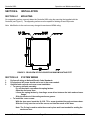
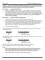
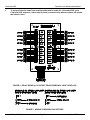
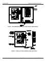
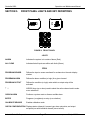
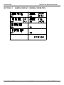
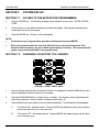
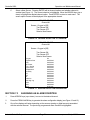
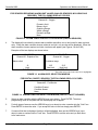
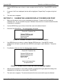
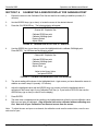
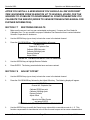
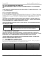
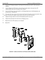
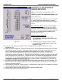
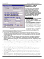
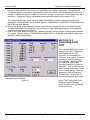
INDUSTRIAL SCIENTIFIC
CORPORATION
1001 Oakdale Road
Oakdale, PA 15071-1500
USA
Phone (412)788-4353
(800)DETECTS
Fax
(800)788-8383
e-mail: info@ indsci.com
CONTROLLER 8000
ENVIRONMENTAL
MONITORING AND
CONTROL SYSTEM
OPERATION AND MAINTENANCE MANUAL
O U R
M I S S I O N
Design - Manufacture - Sell: Highest quality products for the preservation of life and property
Provide: Best customer service available
Controller 8000
Operation and Maintenance Manual
THE CONTROLLER 8000
• POWERFUL INTELLIGENCE
• MAXIMUM FLEXIBILITY
• INCREDIBLE EASE OF USE
• MENU DRIVEN SOFTWARE
• USER-FRIENDLY PROGRAMABILITY
• THE CONTROLLER 8000 WALKS YOU THROUGH EACH STEP
• MAXIMUM VERSATILITY
• MONITORS AND CONTROLS MORE
• GASES, ENVIRONMENT, SECURITY
• DATALOGGING AND MODEM SOFTWARE OPTIONS
• MANY OPTIONS FOR NOW AND TOMORROW
Industrial Scientific Corporation
Page 1
8000_v1.DOC
24 April 2000
Controller 8000
Operation and Maintenance Manual
INDUSTRIAL SCIENTIFIC CORPORATION CONTROLLER 8000
Environmental, Security, & Safety Monitor/Controller
Engineered for areas such as:
•
Controlled Environmental Vaults
•
Battery Rooms
•
Cable Entrance Vaults
•
Plant Wide Monitoring
•
Mobile Radio Cell Sites
•
Safety Monitoring
•
Cable Huts
•
Indoor Parking Garages
•
Small CDOs
•
Process Control
•
Fence Line Monitoring
•
Waste Water Treatment
Industrial Scientific Corporation
Page 2
8000_v1.DOC
24 April 2000
Controller 8000
Operation and Maintenance Manual
BEFORE ATTEMPTING TO INSTALL OR OPERATE, PLEASE READ THE
MANUAL.
BEFORE ATTEMPTING TO PROGRAM THE INDUSTRIAL SCIENTIFIC
CONTROLLER 8000, YOU MUST ENTER THE
ACCESS CODE
The Access Code is provided to ensure tamper-proof security
for the Industrial Scientific Controller 8000.
Your access code has been assigned as:
1.
2.
3.
4.
5.
6.
Push ENTER
Push PRGM SENSOR
Push UP ARROW
Push DOWN ARROW
Push UP ARROW
Push ENTER
REFER TO SECTION 7.1 BEFORE ATTEMPTING TO PROGRAM THE CONTROLLER 8000.
Industrial Scientific Corporation
Page 3
8000_v1.DOC
24 April 2000
Controller 8000
Operation and Maintenance Manual
TABLE OF CONTENTS
Section 1.
Section 1.1
INTRODUCTION ........................................................................................................................................................................ 6
DESCRIPTION .......................................................................................................................................................................... 6
Section 1.2
MULTI-SENSOR CAPABILITY ...................................................................................................................................................... 6
Section 1.3
CONTROLLER 8000 FEATURES.................................................................................................................................................. 6
Section 1.4
RS-232 COMMUNICATIONS CAPABILITIES .................................................................................................................................. 7
Section 1.5
SENSOR/TRANSDUCERS ASSEMBLIES ...................................................................................................................................... 7
Section 2.
Section 3.
CONTROLLER 8000 SPECIFICATIONS........................................................................................................................................ 9
OPERATION PROTOCOL OVERVIEW ...................................................................................................................................... 10
Section 3.1
SYSTEM SET-UP ..................................................................................................................................................................... 10
Section 3.2
NORMAL OPERATION .............................................................................................................................................................. 10
Section 3.3
ALARM CONDITION ................................................................................................................................................................. 11
Section 3.4
PROGRAMMING OPTIONS ....................................................................................................................................................... 11
Section 4.
INSTALLATION ........................................................................................................................................................................ 13
Section 4.1
MOUNTING............................................................................................................................................................................. 13
Section 4.2
SYSTEM WIRING .................................................................................................................................................................... 13
Section 5.
Section 5.1
FRONT PANEL LIGHTS AND KEY DEFINITIONS ........................................................................................................................ 18
SAMPLE DISPLAY -NORMAL OPERATION .................................................................................................................................. 19
Section 6.
START-UP............................................................................................................................................................................... 20
Section 7.
SYSTEM SET-UP...................................................................................................................................................................... 21
Section 7.1
ACCESS TO THE KEYPAD FOR PROGRAMMING....................................................................................................................... 21
Section 7.2
ASSIGNING A FUNCTION TO A CHANNEL ................................................................................................................................ 21
Section 7.3
ASSIGNING AN ALARM CONDITION ......................................................................................................................................... 22
Section 7.4
DEFINING A CONTROL OUTPUT CONDITION ........................................................................................................................... 24
Section 7.5
CALIBRATING A SENSOR DISPLAY FOR ZERO/LOW POINT...................................................................................................... 25
Section 7.6
CALIBRATING A SENSOR FOR GAIN/HIGH POINT .................................................................................................................... 26
Section 7.7
RESTORING DEFAULTS .......................................................................................................................................................... 27
Section 7.8
ADJUST OFFSET..................................................................................................................................................................... 27
Section 7.9
CHECKING A CHANNEL’S CONFIGURATION AND PROGRAMMING SET-UP PARAMETERS.......................................................... 28
Section 7.10
MAIN MENU INFORMATION ..................................................................................................................................................... 30
Section 7.11
MAIN DISPLAY BACKLIGHT ..................................................................................................................................................... 30
Section 7.12
RECOMMENDED ALARM LEVELS ............................................................................................................................................. 30
Section 8.
THEORY OF OPERATION ......................................................................................................................................................... 31
Section 9.
MAINTENANCE........................................................................................................................................................................ 33
Section 9.1
SYSTEM FUNCTIONAL PERFORMANCE VERIFICATION ............................................................................................................ 33
Section 9.2
LCD REPLACEMENT............................................................................................................................................................... 33
Section 10.
TROUBLESHOOTING .............................................................................................................................................................. 35
Section 11.
REPLACEMENT PARTS ............................................................................................................................................................ 36
Section 12.
CHANNEL DEFINER ................................................................................................................................................................ 37
Section 12.1
HARDWARE SETUP ................................................................................................................................................................ 37
Section 12.2
PROGRAM INSTALLATION ....................................................................................................................................................... 37
Section 12.3
STANDARD GAS SENSOR DEFINITION .................................................................................................................................... 38
Section 12.4
CUSTOM CHANNEL DEFINITION .............................................................................................................................................. 39
Section 12.5
CONFIGURE RS232 PORT....................................................................................................................................................... 40
Section 13.
OPTIONAL DATALOGGING CAPABILITY..................................................................................................................................... 41
Section 14.
WARRANTY ............................................................................................................................................................................ 42
Industrial Scientific Corporation
Page 4
8000_v1.DOC
24 April 2000
Controller 8000
Operation and Maintenance Manual
Section 1. INTRODUCTION
The Industrial Scientific Corporation Controller 8000, Environmental Monitoring and Control System is
engineered to monitor and control environmental conditions in facilities and confined spaces for personnel and
site protection.
The Controller 8000 consists of a microprocessor-based Controller which processes signals from various
transmitters and sensing/detection devices.
The goal of this product is to eliminate the non-integrated components from many different vendors
requiring multiple systems and extensive wiring to maintain. The Controller 8000 does simplify,
modernize, and cut the total cost of the system, installation, and maintenance.
SECTION 1.1
DESCRIPTION
The Controller 8000 is engineered to monitor a variety of sensor/transducer functions that can detect any or all
of the following conditions: gas levels, security, environmental, and energy management.
The Controller 8000 is designed to monitor up to 8 or 16 different channels. The Controller 8000 is password
protected and programmable. It can accept either analog or digital input (4-20 mA or on/off signals), display
levels or conditions detected by the sensors, and provide control outputs.
SECTION 1.2
MULTI-SENSOR CAPABILITY
The following is a partial listing of available sensors/transducers (we can add others that you may require):
•
•
•
•
•
•
•
•
•
•
•
Ammonia (NH3) Gas
Carbon Monoxide (CO) Gas
Chlorine (Cl2) Gas
Combustible Gases
Ethylene Oxide Gas (ETO)
Fluorocarbons
Hydrogen (H2) Gas
Hydrogen Cyanide (HCN) Gas
Hydrogen Sulfide (H2S) Gas
Nitrogen Dioxide (NO 2) Gas
Oxygen (O2) Gas
SECTION 1.3
•
•
•
•
•
•
•
•
•
•
•
Ozone (03) Gas
Phosphine (PH3) Gas
Radon Gas
Sulfur Dioxide (SO2) Gas
Intrusion
AC Power Alarm
Air Flow Alarm
Liquid Level Alarm
Humidity
Temperature
Smoke/Fire Alarm
CONTROLLER 8000 FEATURES
The Controller 8000 provides power to, and receives signals from, transducers. The sensor/transducer signals
are processed by the Controller to provide outputs, alarms, and communication.
Programmable keys on the front panel of the Controller 8000 allow for field programmability if additional
sensor/transducers are added later, or if such needs as alarm levels or objects to be controlled need to be
changed. It is tamper-proof, requiring the user to enter a security code. The Controller has an external reset
button so that the alarms can be silenced without requiring access to the internal controls.
Sixteen 5 amp form C output relays are available in each system package. Each channel can control all
system relays to permit a sophisticated control logic protocol.
Industrial Scientific Corporation
Page 5
8000_v1.DOC
24 April 2000
Controller 8000
SECTION 1.4
Operation and Maintenance Manual
RS-232 COMMUNICATIONS CAPABILITIES
Standard in each system is a RS-232 serial port to allow for external communication to a computer or other
processing device. PC software is available for remote call out monitoring capabilities, as well as the ability to
call into the Controller via optional modem. Optional Windows 3.1 based software for datalogging is available.
Please contact a Industrial Scientific Sales Engineer for more information.
SECTION 1.5
SENSOR/TRANSDUCERS ASSEMBLIES
The overall system design offers both individual and multiple sensor/transducer assemblies. Individual sensor
assemblies are available in either NEMA 7 explosion and weather-proof enclosures for classified areas, or
NEMA 4X weather-proof enclosures.
Industrial Scientific Corporation offers an extensive range of gas detecting/sensing transmitters as well as other
environmental sensors. Contact a Industrial Scientific Sales Engineer for complete information on the
transmitter product line.
FIGURE 1. CONTROLLER 8000 - ENCLOSURE LAYOUT (EXTERIOR VIEW)
Industrial Scientific Corporation
Page 6
8000_v1.DOC
24 April 2000
Controller 8000
Operation and Maintenance Manual
FIGURE 2. ENCLOSURE LAYOUT (INTERNAL VIEW) - SWING-OUT PAN EL NOT SHOWN
Industrial Scientific Corporation
Page 7
8000_v1.DOC
24 April 2000
Controller 8000
Operation and Maintenance Manual
SECTION 2. CONTROLLER 8000 SPECIFICATIONS
Enclosure:
Fiberglass, Nema 4X, Weatherproof, Lockable
Dimensions:
14 in. x 12 in. x 8 in.
Power Consumption:
< 300 watts
Number of Inputs:
up to 4, 8 or 16
Input Range:
0 - 25 mA
Sensor Excitation Voltage:
24 VDC
Outputs:
16 relays, SPST, 1NO (1A) or 1NC (1B) contact
RS-232 Serial Port
Modem, 1200 baud (optional)
Relay Contact Capacity:
5 Amp @ 250 VAC or 5 Amp @ 30 VDC
Output Connectors:
RS-232 - 9 Pin D Subminiature, Male
Relay - Screw Terminal Strips
Modem - RJ-11 Connector
Power:
Universal; 85VAC to 264VAC, 47Hz to 63Hz, 65-Watt Continuous
Weight:
approx.20 lb.
Industrial Scientific Corporation
Page 8
8000_v1.DOC
24 April 2000
Controller 8000
Operation and Maintenance Manual
SECTION 3. OPERATION PROTOCOL OVERVIEW
SECTION 3.1 SYSTEM SET-UP
Actions required to program each block on the display (after access code has been entered!):
1.
The Amber POWER ON light means there is power to the Controller.
2.
Program each channel for the desired input sensor.
3.
Determine the required alarm logic for each sensor.
4.
Set a value (or values) for an alarm trip condition (if required by the alarm logic).
5.
If required, determine the control (relay) outputs to be activated for each sensor (if in alarm).
6.
Define the conditions for control (relay) activation for each control output.
7.
Define a level (or levels) for control activation for each control output.
Some programming actions apply to all blocks and to the display as a whole. Those include
programming the date, time, day of the week, whether outputs latch or don’t latch, and assigning a relay
to energize when the alarm activates.
8.
Document the set up procedure and instruct personnel as to what action needs to be taken (if any), if
your system goes into alarm.
SECTION 3.2 NORMAL OPERATION
1.
The Amber POWER ON light means there is power to the Controller.
2.
The Green ALL CLEAR light is on.
3.
The display updates measured values in the main menu which shows the status of all sensors and
other inputs.
4.
The Controller activates alarm and/or control (relay) outputs as defined during system set-up.
5.
No channels are highlighted.
6.
For units with the modem option, data is transferred out over the modem when polled by a central
station.
Industrial Scientific Corporation
Page 9
8000_v1.DOC
24 April 2000
Controller 8000
Operation and Maintenance Manual
SECTION 3.3 ALARM CONDITION
1.
The Amber POWER ON light means there is power to the Controller.
2.
The Red ALARM light illuminates. The Green ALL CLEAR light turns off.
3.
The channel of each sensor is highlighted when in the alarm condition.
4.
The audible alarm activates.
NOTE:
• The system will not reset until the alarm condition has been corrected and the CLEAR ALARM key
has been pressed.
•
During an alarm condition, pressing either the CLEAR ALARM key or the external RESET switch will
silence the audible alarm. The alarm condition will not be cleared unless the channel is out of the alarm
condition, and the CLEAR ALARM key has been pressed.
•
Each sensor can activate a number of output relays all under different control conditions
5.
Control outputs may be activated if they were programmed to activate on the condition which caused
the alarm.
6.
For units with the optional modem, the modem will call the control station and transfer data regarding
the nature of the alarm.
7.
To return to normal operation, the CLEAR ALARM key must be pressed and the alarm condition must
be clear.
SECTION 3.4
PROGRAMMING OPTIONS
SECTION 3.4.1
TYPES OF SENSORS- (MANY MORE TYPES AND RANGES ARE AVAILABLEPLEASE CONSULT INDUSTRIAL SCIENTIFIC CORPORATION AT 1-800-DETECTS TO SOLVE
YOUR DETECTION/ MONITORING NEEDS!)
•
•
•
•
•
•
•
•
•
•
•
•
•
•
•
Ammonia (NH3) Gas
Carbon Monoxide (CO) Gas
Chlorine (Cl2) Gas
Combustible Gases
Ethylene Oxide Gas (ETO)
Fluorocarbons
Hydrogen (H2) Gas
Hydrogen Cyanide (HCN) Gas
Hydrogen Sulfide (H2S) Gas
Nitrogen Dioxide (NO 2) Gas
Oxygen (O2) Gas
Ozone (03) Gas
Phosphine (PH3) Gas
Radon Gas
Sulfur Dioxide (SO2) Gas
Industrial Scientific Corporation
•
•
•
•
•
•
•
Page 10
Intrusion
AC Power Alarm
Air Flow Alarm
Liquid Level Alarm
Humidity
Temperature
Smoke/Fire Alarm
8000_v1.DOC
24 April 2000
Controller 8000
Operation and Maintenance Manual
SECTION 3.4.2 ALARM CONDITIONS
Alarm on the Controller when:
q
q
q
q
q
q
q
Exceed a Limit
Below a Limit
Outside a Range
Within a Range
Condition Present
Condition Absent
None
SECTION 3.4.3 CONTROL (RELAY) CONDITIONS
Energize relay (activate, close contact) when:
q
q
q
q
q
q
q
Exceed a Limit
Below a Limit
Outside a Range
Within a Range
Condition Present
Condition Absent
None
SECTION 3.4.4 CONTROL RELAY OUTPUTS
Output (Relay) Number
1
2
3
4
5
6
7
8
Industrial Scientific Corporation
Possible External Device Configuration
Exhaust fan
External warning light
Air conditioning unit
Emergency light
Heater
Sump pump
Generator
Battery power
Page 11
8000_v1.DOC
24 April 2000
Controller 8000
Operation and Maintenance Manual
SECTION 4.
INSTALLATION
SECTION 4.1
MOUNTING
On a supporting surface, securely fasten the Controller 8000 using the mounting feet supplied with the
Controller (see Figure 3). The supporting surface must be capable of holding at least 50 pounds.
Note: Modification to the enclosure may change the enclosures NEMA rating.
FIGURE 3. REAR VIEW OF ENCLOSURE SHOWING MOUNTING FEET
SECTION 4.2
1.
2.
3.
SYSTEM WIRING
Perform all wiring to National Electric Code Standards.
DC signal and AC power should not be run in the same conduit.
Optional latch removal and cover screw installation
• To remove old latch assembly:
Pry off the plastic caps above the spring latches.
Open the enclosure door.
Loosen the spring latches by inserting a screw driver between the latch and enclosure
flange.
Slide the latch out of the mating enclosure groove.
• To install the cover screws:
With the door open, insert the 10-32 X .75 in. screw (provided) through enclosure door.
Slide the O-ring over the end of the screw, and into the recess of the door.
Note: The O-ring is used to retain the screw in place and is not needed for sealing the
enclosure door.
Industrial Scientific Corporation
Page 12
8000_v1.DOC
24 April 2000
Controller 8000
Operation and Maintenance Manual
CAUTION:
Access to live AC electrical components located on the inside of this Controller should
be limited to qualified personnel. Use of a padlock on the supplied quick release latches or use of the
supplied screws in place of the latch comply with CSA certification requirements
SECTION 4.2.1
1.
POWER CONNECTIONS
Connect the incoming power wires to the hot (+), neutral (-) and ground connections on POWER IN
cable gland on the bottom of the enclosure. Use #14-#18 gauge wire. Insert the power wires into the
HOT, NEUTRAL, and GROUND terminal block TB3 (see Figure 4). Secure the wires by turning each
screw snug into the connector. Tighten the cable gland cap onto its body. The incoming power wires
should come from an approved, properly fused, dedicated 15 A., 110 VAC circuit breaker or
UPS (Universal Power Supply).
SECTION 4.2.2
CONTROL OUTPUT CONNECTIONS
1.
Use #14-#18 AWG control wire with THWN, TMWN, MTW or equal insulation.
2.
Connect external control wires to the control/output relays through terminal blocks TB1, TB2, TB4, and
TB5. Thread the wires through the ALARM/CONTROL OUT cable gland. Add holes and cable glands
as needed to provide enough openings for all required wiring (use caution when drilling or pounding
holes). Be careful to not drill into electronics. Remove fiberglass dust from the enclosure using a
compressed air source. Tighten the cable gland caps onto the cable gland bodies.
3.
Wire the individual relays as follows:
To supply power or to close a contact upon relay activation (Normally Open, NO), wire to the contacts of an
output relay as follows
Relay Terminal
COM
NO
External Wire Identification
Control Power
Device-to-be-energized
To remove power or to open a contact upon relay activation (Normally Closed, NC), wire to the contacts of an
output relay as follows:
Relay Terminal
COM
NC
External Wire Identification
Control Power
Device-to-be-de-energized
Refer to Figures 4 and 5 for the location of the terminal blocks and for wiring examples.
Power for energizing external devices should be supplied from external sources.
NOTE:
•
It is recommended that external devices which will be controlled should be powered from a
different circuit breaker than the circuit breaker that is powering the Controller 8000. This
wiring configuration will make maintenance and calibration work more conveniently.
•
Relay contact capacity is 5 Amps at 250 VAC or 5 Amps at 30 VDC.
Industrial Scientific Corporation
Page 13
8000_v1.DOC
24 April 2000
Controller 8000
•
Operation and Maintenance Manual
To prevent inductive loads from coupling spikes and to isolate the Controller 8000, use a
Controller 8000 output as a slave relay to power an external relay whose contacts will operate
the inductive load.
FIGURE 4. RELAY BOARD (A 16 OUTPUT RELAY BOARD WILL HAVE 16 RELAYS)
FIGURE 5. WIRING CONFIGURATION OPTIONS
Industrial Scientific Corporation
Page 14
8000_v1.DOC
24 April 2000
Controller 8000
Operation and Maintenance Manual
SECTION 4.2.3
1.
SENSOR CONNECTIONS
All sensor signal connections are made to the Sensor Terminal Strip on the rear side of the Swing-out
Panel (see Figures 6 and 7).
NOTE:
• The Controller 8000 has been fitted with a shield that goes over the sensor terminal strip. This cover helps
keep RF signals from interfering with the Controller electronics. To access the terminal strip, remove the
two #6 self-tapping screws from the far right of the shield on the back of the swing-out panel. Replace the
cover when all sensor inputs have been connected to the terminal block.
•
Sensor wires should be separated from 110 VAC power and control wires. If conduit is used,
sensor wires and control wires should not be together.
•
Sensors cables should be twisted, insulated, and shielded control and instrumentation wire. The
wire size should be #18-#22 gauge. Use Carol Cable Co., Model C2535 or equal. Use 2 conductor
cable for 2-wire transmitters and 3 conductor cable for 3-wire transmitters.
2.
Cut a hole(s) in the fiberglass enclosure for the sensor wires. Refer to Figure 6 for a recommended
location for the hole(s). Cover the inside of the hole to prevent fiberglass dust from coating the inside of
the enclosure. Be careful to not drill into electronics.
3.
Remove fiberglass dust from the enclosure using a compressed air source.
4.
Insert either conduit to the hole(s) using conduit access fittings or install cable gland(s) into the hole(s).
5.
Thread the sensor wires into the enclosure and route the wires to the terminal strip on the rear of the
Swing-out Panel. Allow enough wire length to enable the Swing-out Panel to open and close without
putting tension on the sensor wires.
6.
Make connections as follows (see Figure 7):
TERMINAL STRIP
DESIGNATION
+ (24 VDC)
1 - 16
G (Sensor Ground)
SENSOR WIRING
2-WIRE SENSOR
3-WIRE SENSOR
+ Terminal of Sensor
- Terminal of Sensor
+ Terminal of Sensor
mA Terminal of Sensor
- Terminal of Sensor
NOTE: The sensor wire shield (foil) should be connected to earth ground on one end. Connect sensor wire
shields only to the 2 x 8 connector terminal block located on the Swing Out Panel labeled Shield Ground.
7.
Ensure all wiring is neatly routed and secure. Use cable ties and cable tie mounts to secure the wires
to the enclosure walls and the Swing-out Panel.
8.
Wiring of the sensors to the Controller 8000 is complete. Close the Swing-out Panel and secure it to
the enclosure with the panel latch.
9.
Turn on Power.
Industrial Scientific Corporation
Page 15
8000_v1.DOC
24 April 2000
Controller 8000
Operation and Maintenance Manual
FIGURE 6. RECOMMENDED ROUTING OF SENSOR INPUT WIRE EXAMPLE
FIGURE 7. SWING-OUT PANEL (INTERNAL VIEW, DOOR OPEN)
Industrial Scientific Corporation
Page 16
8000_v1.DOC
24 April 2000
Controller 8000
SECTION 5.
Operation and Maintenance Manual
FRONT PANEL LIGHTS AND KEY DEFINITIONS
FIGURE 8. FRONT PAN EL
LIGHTS
ALARM
Indicates the system is in a state of alarm (Red).
ALL CLEAR
Indicates that all inputs are within safe limits (Green).
KEYS
PROGRAM SENSOR
Defines the input or sensor monitored for a channel on the main display
window.
PROGRAM ALARM
Defines the alarm condition (or logic) for a given channel.
PROGRAM OUTPUT
Defines the condition (or logic) under which an output relay will be
activated.
↑ ↓
ARROW keys (up or down) used to select the active channel and to make
menu selections.
CLEAR ALARM
Performs a system reset or silences audible alarm.
ENTER
Programs (or registers) an entry (or a selection).
CALIBRATE SENSOR
Enables calibration mode.
CHECK CONFIGURATION Displays status (channel #, sensor type, alarm set points, and output
set points) on each individual channel (one at a time).
Industrial Scientific Corporation
Page 17
8000_v1.DOC
24 April 2000
Controller 8000
SECTION 5.1
Operation and Maintenance Manual
SAMPLE DISPLAY - NORMAL OPERATION
Industrial Scientific Corporation
Page 18
8000_v1.DOC
24 April 2000
Controller 8000
SECTION 6.
Operation and Maintenance Manual
START UP
1.
Close the circuit breaker to power the Controller 8000.
2.
If the Controller 8000 has not been programmed, or if sensors are operating correctly, then the Green
ALL CLEAR light will be on and no alarms will be indicated.
3.
Press the RESET button or the CLEAR ALARM key to silence the audio alarm.
4.
If display contrast needs to be adjusted do the following:
a.
Turn the black knob on the Swing Out Panel and unlatch the panel. Swing open the panel to
obtain access to the internal enclosure.
b.
Locate the opening on the left (from the rear) of the electronics enclosure labeled CONTRAST
ADJUST (see Figure 7).
c.
Insert an instrument screwdriver into the CONTRAST ADJUST potentiometer and turn the
screwdriver to obtain the desired contrast.
5.
Even if the Controller is pre-programmed, verify the programming or perform all programming as
defined in Section 7.
6.
The backlight of the display will time out in approximately 5 minutes. To backlight the display press any
key, or press the Red RESET button on the left side of the Controller 8000.
Industrial Scientific Corporation
Page 19
8000_v1.DOC
24 April 2000
Controller 8000
Operation and Maintenance Manual
SECTION 7.
SYSTEM SET-UP
SECTION 7.1
ACCESS TO THE KEYPAD FOR PROGRAMMING
1.
Press the ENTER key. The following message will be displayed on the screen: ENTER ACCESS
CODE.
2.
Press four keys in a pre-defined sequence to activate the keypad. This sequence represents the
combination to a lock on the keypad.
3.
Press the ENTER key. Channel 1 will be highlighted.
NOTE:
•
To exit the set-up or program mode and return to the main menu press ENTER.
•
Once in the program mode, the Controller 8000 will return to the monitoring mode if the
Controller does not detect a key-press within approximately 15 minutes. This ensures that the
system cannot be left indefinitely in the program mode.
SECTION 7.2
ASSIGNING A FUNCTION TO A CHANNEL
FIGURE 9. FRONT PAN EL KEYS
1.
After the access code has been entered and Channel 1 is highlighted, Press the ARROW key (up or
down) to highlight the desired channel to be changed.
2.
Press the PRGM SENSOR key to obtain Figure 10 display. The channel number representing that
block will be displayed. Sensor condition is displayed (see Figure 10).
3.
Press ARROW keys (up or down) to move to desired selections. The selection will be highlighted.
A.
Turn Sensor ON - activates sensor. Pressing ENTER will enable this sensor for the desired
channel and will return you to the main menu.
B.
Turn Sensor OFF - de-activates sensor. Pressing ENTER will disable sensor and will return
you to the main menu.
Industrial Scientific Corporation
Page 20
8000_v1.DOC
24 April 2000
Controller 8000
C.
Operation and Maintenance Manual
Select a New Sensor. Pressing ENTER will list channel options and whether channel is
enabled (see Figure 11). The current selection is highlighted. Move the ARROW keys (up or
down) to highlight the desired channel option. Press ENTER to return to main menu. The
sensor option chosen will be displayed in the appropriate channel.
SENSOR SELECT
Channel #1
Sensor: Oxygen is [Off]
Turn Sensor ON
Turn Sensor OFF
Select a New Sensor
FIGURE 10. SENSOR SELECTION 1ST WINDOW
SENSOR SELECT
Channel #1
Sensor: Oxygen is [Off]
Turn Sensor ON
Turn Sensor OFF
Select a New Sensor
Oxygen
Explosive Gas
H2S
AC Power
Fire / Smoke
Liquid Level
Temperature
Humidity
H2
CO
CL
Intrusion
H2S high rng
HCN
SO2
NO2
O3
UnDefined
UnDefined
UnDefined
UnDefined
UnDefined
UnDefined
UnDefined
UnDefined
UnDefined
UnDefined
UnDefined
UnDefined
UnDefined
UnDefined
20.00 mA
FIGURE 11. SENSOR SELECTION 2ND WINDOW
SECTION 7.3
ASSIGNING AN ALARM CONDITION
1.
Press ARROW keys (up or down) to move to the desired channel.
2.
Press the PRGM ALARM key to generate the alarm configuration display (see Figure 12 and 13).
3.
One of two displays will arise depending on the sensors (analog or digital sensors) associated
with the selected channel. The previously programmed alarm condition is highlighted.
Industrial Scientific Corporation
Page 21
8000_v1.DOC
24 April 2000
Controller 8000
Operation and Maintenance Manual
FOR SENSORS REQUIRING ALARM LIMIT VALUES (ANALOG SENSORS, INCLUDING GAS
SENSORS), THE FOLLOWING DISPLAY OCCURS:
ALARM STATE
Channel #1 - Oxygen
Exceed a Limit
Below a Limit
Outside a Range
Within a Range
Exceed Low/High
None
FIGURE 12. ALARM CONDITION SELECTION WINDOW (ANALOG SENSORS)
4.
The display will now show the chosen alarm condition and either one or two boxes for alarm trip level
entry. When the alarm condition chosen relates to one limit, only one box will be displayed. When the
alarm condition chosen requires two limits, two boxes will appear (see Figures 13A and 13B)
Examples of the two displays are shown below:
ALARM STATE
Channel #2 - Explosive Gas
Above a limit
ALARM STATE
Channel #1 - Oxygen
Outside a range
10
Limit
FIGURE 13A
19.5
Low Limit
23.5
High Limit
FIGURE 13B
The "Limit" box or the "Low Limit" box is highlighted.
FIGURE 13. ALARM LEVEL SELECTION WINDOW
FOR DIGITAL (ON/OFF) SENSORS, THE FOLLOWING DISPLAY OCCURS:
ALARM STATE
Channel #5 - Fire/Smoke
Condition Present
Condition Absent
None
FIGURE 14. ALARM CONDITION SELECTION WINDOW (DIGITAL, ON/OFF SENSORS)
5.
Select an alarm condition with the ARROW keys (up or down). Press ENTER. The alarm
programming mode is complete and the main display will re-appear.
6.
For both types of sensors use the ARROW keys (up or down) to enter a number into the "Limit" box.
Press ENTER to store the value. If you accept the value in the box simply press ENTER.
7.
If a second limit box is displayed, that box will be highlighted, then use the ARROW keys (up or
down) to enter a number into the "Limit" box. Press ENTER to set the value and you then return
to the main menu.
Industrial Scientific Corporation
Page 22
8000_v1.DOC
24 April 2000
Controller 8000
SECTION 7.4
Operation and Maintenance Manual
DEFINING A CONTROL OUTPUT CONDITION
1.
Highlight the desired channel with the ARROW keys (up or down).
2.
Press the PRGM OUTPUT key.
3.
Use ARROW keys (up or down) to select output number. The highlighted number will change. Press
ENTER when the proper output number is selected.
OUTPUT CONTROL
Channel #1 - Oxygen
Select output #1
FIGURE 15. OUTPUT CONTROL SELECTION 1ST WINDOW
4.
One of two displays will arise depending on the sensor associated with the selected channel.
For sensors requiring actions at specific
analog levels, the following display occurs:
OUTPUT CONTROL
Channel #1 - Oxygen
For sensors requiring actions based on on/off
conditions, the following display occurs:
OUTPUT CONTROL
Channel #5 - Fire/Smoke
Select Output #1
Exceed a Limit
Below a Limit
Outside a Range
Within a Range
Exceed Low/High
None
Select Output #1
Condition Present
Condition Absent
None
FIGURE 16. OUTPUT CONTROL SELECTION 2ND WINDOWS
5.
Select a control condition with the ARROW key (up or down). Press ENTER. For the digital (on/off)
control conditions, the control output programming mode is complete, and the main menu will reappear.
6.
For the analog sensors, the display will now show the chosen alarm condition and either one or two
boxes for control activation limit entry. When the control condition chosen relates to one limit, only one
box will be displayed. When the control condition chosen requires two limits, two boxes will appear.
Examples of the two displays are shown below:
OUTPUT CONTROL
Channel #2 - Explosive Gas
Select Output #2
Exceed a Limit
OUTPUT CONTROL
Channel #1 - Oxygen
Select Output #2
Outside a range
10
10
20
Limit
Low Limit
High Limit
The "Limit" box or the "Low Limit" box is highlighted.
FIGURE 17. OUTPUT CONTROL LEVEL SELECTION 3RD WINDOW
Industrial Scientific Corporation
Page 23
8000_v1.DOC
24 April 2000
Controller 8000
Operation and Maintenance Manual
7.
Use the ARROW keys (up or down) to enter a number into the "Limit" box. Press ENTER to set the
value.
8.
If a second “Limit” box is displayed, that box will be highlighted. Repeat Step 7 to register a high limit
value.
9.
The main menu re-appears.
SECTION 7.5
CALIBRATING A SENSOR DISPLAY FOR ZERO/LOW POINT
1.
Make sure the sensor is not in a gas contaminated environment. If unsure use Zero Grade Air
Calibration Gas. For any questions on proper Calibration Gases feel free to contact Industrial Scientific
Corporation for assistance.
2.
Use the ARROW keys (up or down) to locate the cursor in the desired channel.
3.
Press the CAL SENSOR key. The following display will appear:
CALIBRATION
Channel #2 - Explosive Gas
Calibrate ZERO/low point
Calibrate GAIN/high point
Restore Defaults
Adjust Offset
FIGURE 18. CALIBRAT ION SELECTION 1ST WINDOW EXAMPLE
4.
Use ARROW keys (up or down) to select Calibrate ZERO/low point. Press ENTER to select
calibration for zero input; or press the down ARROW to select gain or span calibration. Then press
ENTER.
5.
For calibration of the zero level, the following display appears:
CALIBRATION
Channel #2 - Explosive Gas
Calibrate ZERO/low point
Calibrate GAIN/high point
Restore Default
Adjust Offset
0
Adjust to the Known Value
and press ENTER.
FIGURE 19. CALIBRATION OF ZERO/LOW POINT 2ND WINDOW EXAMPLE
6.
With the sensor exposed to a zero reading condition (no background of gas) adjust the reading in the
highlighted box to read zero or the low point. Press ENTER.
7.
The main menu re-appears. The selected channel will not be zeroed until the span is calibrated.
Industrial Scientific Corporation
Page 24
8000_v1.DOC
24 April 2000
Controller 8000
SECTION 7.6
Operation and Maintenance Manual
CALIBRATING A SENSOR DISPLAY FOR GAIN/HIGH POINT
1.
Expose the sensor to the Calibration/Test Gas and wait for the reading to stabilize (normally 2-3
minutes).
2.
Use the ARROW keys (up or down) to locate the cursor in the desired channel.
3.
Press the CAL SENSOR key. The following display will appear:
CALIBRATION
Channel #2 - Explosive Gas
Calibrate ZERO/low point
Calibrate GAIN/high point
Restore Default
Adjust Offset
FIGURE 20. CALIBRATION SELECTION 1ST WINDOW
4.
Use the ARROW key (up or down) to move the highlighted block to calibrate GAIN/high point.
Press ENTER. You will then see the following screen:
CALIBRATION
Channel #2 - Explosive Gas
Calibrate ZERO/low point
Calibrate GAIN/high point
Restore Defaults
Adjust Offset
50
Adjust to the Known Value
and press ENTER.
FIGURE 21. CALIBRATION GAIN/HIGH POINT 2ND WINDOW
5.
The actual reading will be shown in the highlighted block. Again ensure you have allowed the sensor to
stabilize as noted in step #1 (normally 1-2 minutes).
6.
Adjust the highlighted value with the ARROW keys (up or down) so that the highlighted value is
equivalent to the known input of your Calibration/Test Gas (i.e. If your bottle is 50% LEL then use the
ARROW keys (up or down) to read 50 on the display).
7.
Press ENTER.
8.
The main menu re-appears and the reading in the highlighted block will be the correct calibration value.
Both zero and gain are calibrated. Gain calibration can not be calibrated without calibrating zero
first. Now turn off your Calibration/Test Gas and remove from the sensor.
Note: To adjust the zero and span on a channel, the calibration mode must be entered twice, once for zero
and once for span.
Industrial Scientific Corporation
Page 25
8000_v1.DOC
24 April 2000
Controller 8000
Operation and Maintenance Manual
AFTER YOU INSTALL A NEW SENSOR YOU SHOULD ALLOW SUFFICIENT
TIME (ANYWHERE FROM 30 MINUTES UP TO SEVERAL HOURS) FOR THE
SENSORS TO STABILIZE TO ENVIRONMENTAL CONDITIONS BEFORE YOU
CALIBRATE THE SENSOR (REFER TO SENSOR/TRANSDUCER M ANUAL FOR
FURTHER INFORMATION).
SECTION 7.7
RESTORING DEFAULTS
1.
Make sure the sensor is not in a gas contaminated environment. If unsure use Zero Grade Air
Calibration Gas. For any questions on proper Calibration/Test Gases feel free to contact Industrial
Scientific Corporation for assistance.
2.
Use the ARROW keys (up or down) to locate the cursor in the desired channel.
3.
Press the CAL SENSOR key. The following display will appear:
CALIBRATION
Channel #2 - Explosive Gas
Calibrate ZERO/low point
Calibrate GAIN/high point
Restore Defaults
Adjust Offset
FIGURE 22. CALIBRATION SELECTION 1ST WINDOW
3.
Use the ARROW keys to highlight Restore Defaults.
4.
Press ENTER. The factory preset defaults have now been restored.
SECTION 7.8
ADJUST OFFSET
1.
Use the ARROW keys (up or down) to locate the cursor in the desired channel.
2.
Press the CAL SENSOR key followed by the Adjust Offset key. The following display will appear.
CALIBRATION
Channel #2 - Explosive Gas
Calibrate ZERO/low point
Calibrate GAIN/high point
Restore Defaults
Adjust Offset
0
Adjust to the Offset Counts
and press ENTER.
FIGURE 23. CALIBRATION SELECTION 1ST WINDOW
3.
Use the ARROW keys to modify the Sensor’s zero value within a cumulative count of +/- 5. This
function compensates for inaccuracies in the 4-20mA current loop as well as sensor characteristics.
Industrial Scientific Corporation
Page 26
8000_v1.DOC
24 April 2000
Controller 8000
SECTION 7.8
Operation and Maintenance Manual
CHECKING A CHANNEL’S CONFIGURATION AND
PROGRAMMING ADDITIONAL SET UP PARAMETERS
1.
Use the ARROW keys (up or down) to locate the cursor in the desired channel.
2.
Press the CHECK CONFIG key. The following is an example of a display to show what has been
programmed for the channel.
CHANNEL CONFIGURATION
Channel #1 - Oxygen
Alarm:
High:
Low:
Within a range
23.5
19.5
Outputs:
1 Outside a range
2 None
3 None
4 None
5 None
6 None
7 None
8 None
9 None
10 None
11 None
12 None
13 None
14 None
15 None
16 None
23.5
19.5
FIGURE 24. CHANNEL CONFIGURATION WINDOW
3.
Either press ENTER to return to the main menu or press CHECK CONFIG again to program the relays
to be latching or non-latching, to assign a relay to energize when the alarm activates, and to set the
time-and-date.
NOTE: Corrections or changes to channel configurations cannot be made in the configuration window. The
changes must be made using the PRGM SENSOR, PRGM ALARM, and PRGM OUTPUT keys. If the
CHECK CONFIG key has been pressed, the display appears as shown in Figure 24.
SECTION 7.8.1
DEFINING RELAY OPERATION
The default setting for the relays is that they energize according to their output logic and automatically deenergize when the output logic is no longer satisfied. For example, a relay that is programmed to energize
when a CO concentration exceeds 200 PPM would de-energize when the CO concentration falls below 200
PPM. The latching relay condition can be used when the relays are programmed to the alarm levels; and it is
desired to maintain the devices on that the relays power until the alarm is cleared.
•
To leave the relays in the non-latching state, press ENTER.
•
To convert the relays to the latching state, press the up arrow.
•
To convert the relays to the non-latching state from the latching state, press the down arrow.
•
Press the ENTER key to store the desired state.
NOTE: All alarm conditions must be cleared to unlatch the relays.
Industrial Scientific Corporation
Page 27
8000_v1.DOC
24 April 2000
Controller 8000
Operation and Maintenance Manual
GLOBAL PARAMETERS
Outputs Latch until Reset?
No
Alarm Output Number:
00
Date:
3/14/96
Time: 08:30
Fri
FIGURE 25. GLOBAL PARAMETERS PROGRAMMING WINDOW
(2ND WINDOW OF THE CHECK CONFIGURATION WINDOW)
SECTION 7.8.2 DEFINING A RELAY TO ENERGIZE WHEN THE ALARM ACTIVATES
The default state is relay tied to the Controller 8000 alarm.
•
•
To program a relay to activate when an alarm occurs, press the ARROW key (up or down) until the
desired relay number appears.
To store the relay number as the alarm relay, press ENTER
SECTION 7.8.3 PROGRAMMING THE CURRENT DATE
•
•
•
Use the ARROW keys to enter the proper time, date, and day of the week.
Press ENTER to store a parameter and move to the next parameter.
Press ENTER after setting the day to return to the main menu.
Industrial Scientific Corporation
Page 28
8000_v1.DOC
24 April 2000
Controller 8000
Operation and Maintenance Manual
SECTION 7.9 MAIN MENU INFORMATION
Gas sensor channels display a reading in % by volume, PPM (parts per million), or % LEL (lower explosive
limit).
On the Controller 8000, below each reading is an alarm status indication. The status indicators are LO, HI, and
FL. Their interpretations are:
LO The sensor reading is below a low limit.
HI The sensor reading is above the high limit.
FL If the controller detects a transmitter reading substantially outside the normal 4-20 mA current input range,
it displays "FAULT" or "FL”. A fault display is an indication that there is an open or short in the transmitter loop
or that the sensor is at the end of its usual life. Transmitter connections, wiring, and the sensor must be
evaluated.
The controller is capable of displaying negative readings (readings resulting from transmitter current levels
below 4 mA). Below an input of 2 mA, any channel will display FAULT and FL. Similarly, above a transmitter
current of approximately 22 mA, the display will also show FAULT and FL.
Digital (on/off or good/bad) transmitters such as fire, smoke, liquid level, and intrusion detectors will indicate
one of the following readings:
SAFE
DANGER or FAIL
FAULT or FL
The proper condition or state is present.
The unsafe condition or state is present.
The transmitter reading is out of the expected measurement limits. The
transmitter loop may have an open circuit, a short circuit, or a defective
sensor.
7.10 MAIN DISPLAY BACKLIGHT
The main front panel display has a fluorescent backlight. To conserve the display and the backlight, the
backlight turns off 5 minutes after the last button is pushed (as well as any key or reset push-button). Touching
any key or button such as the large, Red RESET button on the left side will turn the backlight on.
The display can be read without the backlight under most moderate lighting conditions. Backlight contrast
adjustment is described under the Startup Section 6.0.
7.11 RECOMMENDED ALARM LEVELS
It is recommended that programmed alarm levels be appropriate for the application. OSHA (Occupational
Safety and Heath Act standards) limits are shown below for some gases.
Sensor
Oxygen
Explosive Gas
Hydrogen Sulfide
Carbon Monoxide
Chlorine
Low Alarm Level
19.5%
LEL = Lower Explosive Limit
Industrial Scientific Corporation
Page 29
High Alarm Level
23.5%
10% LEL
20 PPM
200 PPM
1 PPM
PPM = Parts Per Million
8000_v1.DOC
24 April 2000
Controller 8000
SECTION 8.
Operation and Maintenance Manual
THEORY OF OPERATION
The block diagram of the system is shown in Figure 26.
The 24 VDC Power Supply converts incoming 110 VAC power to 24 VDC. The 24 VDC output powers the
Printed Circuit Board (PCB), the Amber POWER ON light, and the sensor/transmitters.
The PCB processes the incoming analog sensor signals and transmits the processed signal. The PCB
drives the display, Red ALARM light, Green ALL CLEAR light, the modems, and the Relay/Output PCB.
The Printed Circuit Board executes the monitoring and control program. The PCB digitizes the processed
sensor signals and compares each signal level to a programmed alarm level and to programmed output
conditions. When required, the Controller transmits alarm and relay drive signals. The Controller sends
information for display to the LCD Display Assembly through the PCB. The Controller outputs serial data
directly to the serial port and to the modem (when purchased) through the Controller PCB. Changes to the
monitoring and control program are transmitted to the Controller through the keys. The keys provide access to
the set-up menus for sensor definition, alarm conditions, and output conditions.
The Relay/Output PCB receives drive signals from the PCB and energizes and de-energizes the output relays
on the PCB. The Alarm Horn drives signals and the RESET push-button sense lines are passed through the
Relay/Output to the PCB.
The Inverter PCB receives 5 VDC from the PCB and generates a signal to drive the cold cathode fluorescent
backlight.
All information is displayed on the high resolution (320 x 200 pixel), high contrast LCD Display Assembly. Both
text and graphics can be programmed onto the display.
Industrial Scientific Corporation
Page 30
8000_v1.DOC
24 April 2000
Controller 8000
Operation and Maintenance Manual
FIGURE 26. CONTROLLER 8000 BLOCK DIAGRAM
Industrial Scientific Corporation
Page 31
8000_v1.DOC
24 April 2000
Controller 8000
Operation and Maintenance Manual
SECTION 9. MAINTENANCE
SECTION 9.1 SYSTEM FUNCTIONAL PERFORMANCE VERIFICATION
For safety purposes, system alarms, control outputs, and sensors should be checked for proper
performance regularly.
1.
On each active channel, disconnect the sensor mA signal wire and verify that the display indicates a
FAULT condition. Re-connect the sensor mA signal wire and verify that the display reads a correct
value.
2.
Simulate alarm conditions on each active channel and verify that the Green ALL CLEAR light goes off
and the Red ALARM light and audio alarm turn on.
3.
Simulate conditions which turn outputs on and off to verify that the output relays function properly.
4.
Use the CHECK CONFIG key to verify that all channels are programmed correctly.
5.
De-energize the system and re-energize it. Make sure the system is still programmed correctly.
Ensure that the lights come on and the alarm sounds when the unit is powered.
6.
Check that each sensor is connected to the appropriate input location, and re-calibrate the
sensors at the regular intervals.
7.
If any step is not successfully completed then see Section 10, Troubleshooting. If the problem persists
contact Industrial Scientific Corporation or a qualified service person.
SECTION 9.2
LCD REPLACEMENT (FIGURE 27)
1.
Disconnect power, unlatch the hinged cover and open the enclosure.
2.
Open the Swing-Out Panel by turning the black plastic latch counter-clockwise.
3.
Remove the three #6-32 nuts and #6 lockwashers holding down the larger shield cover.
4.
Remove the shield cover to expose the printed circuit boards.
5.
Remove the three #6-32 x 1 standoffs , the six sets of #6-32 x 3/8 screws, and the #6
that are holding the PC board in place.
6.
Unplug the 5-pin connector on the Inverter circuit board to the left of the Controller PC Board. Unplug
the keypad connector and unplug the two LED connectors.
7.
Pull the PC Board carefully straight up and off the LCD display assembly. The PC Board is
connected to the LCD assembly through a 20-pin plug strip.
8.
Unscrew the four #6-32 x 3/8 screws and lockwashers from the LCD display assembly.
9.
Carefully remove the LCD display assembly from the Swing-Out Panel.
10.
Replace with new LCD display.
Industrial Scientific Corporation
Page 32
8000_v1.DOC
lockwashers
24 April 2000
Controller 8000
Operation and Maintenance Manual
11.
Secure the LCD display assembly to the Swing-Out Panel with the four #6-32 x 3/8 screws and
washers.
12.
Carefully Replace the PC Board by mating the 20-pin female socket on the back of the LCD
display assembly with 20-pin male plug on the PC Board.
13.
Screw the PC Board in place with the #6-32 x 3/8 Phillips head screws, the #6 lockwashers, and
the three #6-32 x 3/8 stand-offs..
14.
Re-connect the 5-pin connector on the Inverter circuit board to the mating connector on the left of the
PC board. Re-connect the keypad connector and re-connect the two LED connectors.
15.
Replace the larger shield cover with the #6 lockwashers and #6-32 hex nuts.
16.
Replace the small shield cover with the two self tapping screws.
17.
Replacement of the LCD assembly is now complete
18.
Apply power.
FIGURE 27. DISPLAY/CONTROL ELECTRONICS EXPLODED VIEW
Industrial Scientific Corporation
Page 33
8000_v1.DOC
24 April 2000
Controller 8000
Operation and Maintenance Manual
SECTION 10. TROUBLESHOOTING
In the event that the Controller 8000 is not performing properly, refer to the table below for problem identification
and remedies.
PROBLEM
POSSIBLE REMEDIES
No display,
No lights
•
•
A transmitter block in
the main display
shows "FAULT"
•
•
•
•
Display remains dim
after the RESET
push-button has
been pressed
Sensor reading is
incorrect
•
Keypad inoperative
•
Display blank, both
front panel lights
out, or display
reading corrupted
Cannot activate an
output
Alarm does not occur
when an alarm limit is
exceeded
•
•
•
•
•
•
•
•
•
•
•
Industrial Scientific Corporation
Check for open circuit breaker in branch circuit supply.
Check for blown fuse on relay output board on the instrument subpanel.
If the breaker and fuse are OK, contact a qualified service person.
Check for an open or short circuit in a transmitter’s wiring.
Replace an aged sensor.
If the transmitter and its wiring are satisfactory, then contact a qualified
service person.
Contact a qualified service person for replacement of the LCD
Recalibrate sensor.
Replace an aged sensor.
If the transmitter and its wiring are satisfactory, then contact a qualified
service person.
Verify access code and verify that the access code is being properly
entered.
If still inoperative contact a qualified service person.
Reset the system by hitting the RESET button.
De-energize the Controller and re-power it.
Contact a qualified service person.
Check output programming.
Wire to another output relay.
If the above two suggestions do not help, contact a qualified service
person.
Check for the proper alarm programming. If this does not help,
contact a qualified service person.
Page 34
8000_v1.DOC
24 April 2000
Controller 8000
Operation and Maintenance Manual
SECTION 11. REPLACEMENT PARTS
Industrial Scientific Corporation
Page 35
8000_v1.DOC
24 April 2000
Controller 8000
Operation and Maintenance Manual
SECTION 12. CHANNEL DEFINER
SECTION 12.1 HARDWARE SETUP
1) A PC with a math co-processor is required for program operation.
2) An RS232 cable with one DB-9 male end is required for connection to the 8000 Controller. The other end of
the RS232 cable is sized to your PC’s available COM port hardware requirements. This may be either a
DB-9 (male or female) or a DB-25 (male or female).
3) Attach the RS232 cable to the 8000 Controller serial port located on the swing-out panel and closest to the
latch. Verify that the shunt jumper, located directly above the serial (DB-9) connector, is placed for RS232
operation.
SECTION 12.2 PROGRAM INSTALLATION
Windows 3.1: Insert the Channel Definer diskette into drive A:. From the Windows 3.1 Program Manager, select
FILE > RUN, then type A:SETUP.EXE at the prompt. The set-up program will begin execution and several
pop-up screens will appear during installation; acknowledge the default values presented by clicking ‘OK’ to
proceed. A Channel Definer group is created during program set-up. Double click on that group. This will open
the Channel Definer program group window and will display the Channel definer icon. Double-click on the icon
to run the program. When the program executes, the Standard Channel Definition screen is displayed (Figure
28).
Windows ’95 & NT: Insert the Channel Definer diskette into drive A:. From the Windows ’95 Program Manager,
select START > RUN, then type A:SETUP.EXE at the prompt. The setup program will begin execution and
several pop-up screens will appear during installation; acknowledge the default values presented by clicking
‘OK’ to proceed. A Channel Definer group is created under main menu item ‘Programs’. Execute Channel
Definer by selecting START > PROGRAMS > CHANNEL DEFINER > CHANNEL DEFINER. When the
program executes, the Standard Channel Definition screen is displayed (Figure 28).
SLIDER CONTROLS:
A slider control is selected by positioning the mouse pointer over the slider control knob and grabbing the knob
by clicking and holding the left mouse button. Thereafter, move the mouse in a vertical fashion to slide up or
down the control. Release the left mouse button at the appropriate selection.
Industrial Scientific Corporation
Page 36
8000_v1.DOC
24 April 2000
Controller 8000
Operation and Maintenance Manual
SECTION 12.3 STANDARD GAS
SENSOR DEFINITION
Note: Prior to defining a sensor slot, the COM
(RS232) port parameters must be set. Click on
‘CONFIG’ and refer to the CONFIGURE RS232 PORT
section (Figure 30).
The Standard Channel Definition screen is comprised
of: sensor definition selection sliders, a numeric
sensor storage list box, and several action command
buttons.
Sensor Definition Sliders: There are three selection
sliders which define a transducer input to an 8000
Controller. The first is the type of gas denoted by the
title ‘Gas’. The second is the gas range denoted by the
title ‘Range’, and the third is the measuring units
denoted by the title ‘Units’.
Defining a Sensor Storage Slot:
1) Select the type of gas monitored. This is
accomplished by moving the slider control to the
appropriate gas.
Figure 28.
3)
4)
5)
6)
7)
8)
2) Select the range of the gas monitored. This is
accomplished by moving the slider control to the
appropriate range.
Select the units of the gas monitored. This is accomplished by moving the slider control to the
appropriate units.
Select the sensor storage slot. The 8000 Controller has 31 user-programmable sensor slots in its ‘Select
A New Sensor’ menu. The first 17, with oxygen defined as sensor slot #1 and ozone defined as sensor
slot #17, have been factory defined and should not be re-defined or over-written. This leaves 14
programmable ‘UnDefined’ slots for new gas sensors--beginning with sensor slot number 18 and
progressing to sensor slot number 31. Modify the ‘Sensor Storage Slot’ number by using the up and down
arrows located to the left of the list box. Change this value to correspond with the appropriate sensor slot
to modify (18-31). The ‘Select a New Sensor’ menu can be accessed via the 8000 Controller front panel
keypad and by pressing the ‘PRGM SENSOR’ key (or refer to Section 7.2 ASSIGNING A FUNCTION TO
A CHANNEL in the 8000 Controller User Manual).
Next, click on the ‘Send’ button to transmit the new sensor definition structure to the 8000 Controller. The
8000 Controller screen will flash (update) three times. After completion, repeat steps #1-5 for additional
sensors or proceed to step #6.
Sensor definition is complete. Refer to Section 7.2 ASSIGNING A FUNCTION TO A CHANNEL in the 8000
Controller User Manual for additional information.
Remove RS232 cable and return 8000 Controller to normal operating mode.
Click the ‘Quit’ button to exit ‘Channel Definer.’
Industrial Scientific Corporation
Page 37
8000_v1.DOC
24 April 2000
Controller 8000
Operation and Maintenance Manual
SECTION 12.4 CUSTOM
CHANNEL DEFINITION
The Custom Channel Definition window
(Figure 29) defines special and/or nontraditional sensors not available in the
Standard Gas Sensor Definition window.
Here, any 4-20mA transducer device can be
defined (eg. Temperature, Pressure, Moisture,
etc.) and its measurement displayed in
engineering units (eg. degC, psi, etc.).
Sensor Definition Fields:
1) ‘Sensor Type’—Currently the only available
sensor type selection is “Analog”;
therefore, by default all transducer inputs
are 4-20mA.
2) ‘Enter sensor description’—This text field
is written to the ‘Select a New Sensor’
table in the 8000 Controller. This field
generally describes a custom sensor (eg.
Temp -50~50 degC). A tilde (~) written in
this field will display an arrow pointing to
Figure 29.
the right and is defined or is equivalent to
the word “TO”. This field accepts a
maximum input of 16 characters. Refer to Section 7.2 ASSIGNING A FUNCTION TO A CHANNEL in the
8000 Controller User Manual for additional information.
3) ‘Enter low limit’—This field is the transducer’s 4mA (engineering units) output value. For example, a
temperature transducer’s range is -50 at 4mA and 50 at 20mA). Therefore in this example a value of -50
would be entered for the transducer’s 4mA output. Do not enter decimal points in this field; that selection
is made at line item #5.
4) ‘Enter high limit’—This field is the transducer’s 20mA native output value. Fore example a temperature
transducer’s range is -50 at 4mA and 50 at 20mA). Therefore in this example, a value of 50 would be
entered for the transducer’s 20mA output. Do not enter decimal points in this field; that selection is made at
line item #5.
5) ‘Select decimal position of limits’—This slider control selects the decimal point position (if any) of the limits
entered. The default value is 0—no decimal point. For example, a temperature transducer’s range is -5.0
at 4mA and 5.0 at 20mA. A value of -50 would be entered for the transducer’s 4mA output with 50 entered
for the transducer’s 20mA output, and, the ‘Select decimal position of limits’ control slider set to 1.
Note: A decimal point counts as one character when determining maximum allowable characters.
6) ‘Enter units’—Input the transducer’s native units (eg. ppm, %lel, psi, degC, etc.).
7) ‘Enter description #1’—This optional text field allows extended sensor descriptions to be entered up to a
maximum of 7 characters. The text is placed just to the right of the ‘Units’ field on the 8000 Controller
display (Eg. TEMPER-).
8) ‘Enter description #2’—This optional text field allows extended sensor descriptions to be entered up to a
maximum of 7 characters. This text is placed to the right of the ‘units’ field and below text description #1
(Eg. ATURE).
9) ‘Select sensor storage slot’—The 8000 Controller has 31 programmable sensor slots in its ‘Select A New
Sensor’ menu. The first 17, with oxygen defined as sensor slot #1 and ozone defined as sensor slot #17,
Industrial Scientific Corporation
Page 38
8000_v1.DOC
24 April 2000
Controller 8000
Operation and Maintenance Manual
have been factory defined and should not be re-defined or over-written. This leaves 14 programmable
‘UnDefined’ slots for new sensors--beginning with sensor slot number 18 and progressing to sensor slot
number 31. Modify the ‘Sensor storage slot’ numeric by using the up and down arrows located to the left of
the list box. Change this value to correspond with the appropriate sensor slot to modify (18-31).
The ‘Select a New Sensor’ menu can be accessed via the 8000 Controller front panel keypad and by
pressing the ‘PRGM SENSOR’ key (or refer to Section 7.2 ASSIGNING A FUNCTION TO A CHANNEL in the
8000 Controller User Manual).
10) Click on the ‘Send’ button to transmit the new custom sensor definition structure to the 8000 Controller.
The 8000 Controller screen will flash (update) three times. After which repeat steps #1-10 for additional
custom sensors or proceed to step #11.
11) Click on the ‘Close’ button to return to the ‘Standard Channel Definition’ screen. Custom sensor definition
is complete. Refer to Section 7.2 ASSIGNING A FUNCTION TO A CHANNEL in the 8000 Controller User
Manual for additional information.
SECTION 12.5
CONFIGURE RS232
PORT
The ‘Configure RS232 Port’ screen
configures your PC’s COM port to
communicate with the 8000
Controller. In some cases, the
‘COM Port’ slider control will require
a change to accommodate your
PC’s hardware. Select the COM
port setting the RS232 cable
connecting the 8000 Controller is
attached to. In most instances, the
default settings for all other controls
will not require change. When the
appropriate COM port has been
selected hit the ‘Close’ button to
lock in the values and return to the
‘Standard Channel Definition’
Figure 30.
Industrial Scientific Corporation
screen. The ‘Config’ button in the
‘Standard Channel Definition’
screen will ghost upon exit and will
not permit re-entry.
Page 39
8000_v1.DOC
24 April 2000
Controller 8000
Operation and Maintenance Manual
SECTION 13. OPTIONAL- DATALOGGING CAPABILITY
The Industrial Scientific MC8000 Datalogging software is a Windows 3.1 program. It will display data received
from the Controller 8000, via serial port in a graph and/or digital format. It will also update the display every 30
seconds.
The datalogging software stores data to the hard-drive from up to 16 sensors at a fixed rate of once every
reading (every 30 seconds). A trend plot of the current 24 hours data can be displayed at the user's discretion.
Once a day at approximately Midnight, the software generates a printed report which shows the maximum and
minimum readings recorded for each sensor. The user can optionally print any previous data in a tabular (nongraphics) format.
When a sensor exceeds its Controller 8000 preset alarm level an automatic report will be written to a file on
hard disk indicating so.
The datalogging software displays a condition of the sensor by changing color of the LED's (Green=OK,
Yellow=Low Alarm, Red=High Alarm, Gray=no Alarm state identified).
Note: Sensor/Channel definitions are preset at factory and modifiable at the factory.
REQUIREMENTS (MINIMUM)
It is recommended that the customer have the following: 486dx66 system including but not limited to: a color
monitor, 420 Meg hard-drive, keyboard, mouse, Windows 3.1, DOS 6.2, and printer (preferably a laser printer if
printing graphs).
It is also highly recommended that the MC8000 Datalogger software be the ONLY application active and running
in Windows 3.1.
Industrial Scientific Corporation
Page 40
8000_v1.DOC
24 April 2000
Controller 8000
Operation and Maintenance Manual
SECTION 14. WARRANTY
Industrial Scientific fixed system products are warranted to be free from defects in material and
workmanship for a period of eighteen (18) months from the date of shipment, or one (1) year from the date of
first use, whichever occurs first, except where otherwise stated in writing in Industrial Scientific literature
accompanying the product.
The above warranty does not include sensors, pumps, or filters, all of which are warranted to be free
from defects in material and workmanship for one year from the date of shipment, except where otherwise
stated in writing in Industrial Scientific literature accompanying the product.
Limitation of Liability
INDUSTRIAL SCIENTIFIC MAKES NO OTHER WARRANTIES, EITHER EXPRESSED OR
IMPLIED, INCLUDING BUT NOT LIMITED TO THE WARRANTIES OF MERCHANTABILITY OR
FITNESS FOR PARTICULAR PURPOSE.
SHOULD THE PRODUCT FAIL TO CONFORM TO THE ABOVE WARRANTY, BUYER'S ONLY
REMEDY AND INDUSTRIAL SCIENTIFIC'S ONLY OBLIGATION SHALL BE, AT INDUSTRIAL
SCIENTIFIC'S SOLE OPTION, REPLACEMENT OR REPAIR OF SUCH NON-CONFORMING
GOODS OR REFUND OF THE ORIGINAL PURCHASE PRICE OF THE NON-CONFORMING
GOODS. IN NO EVENT WILL INDUSTRIAL SCIENTIFIC BE LIABLE FOR ANY OTHER
SPECIAL, INCIDENTAL OR CONSEQUENTIAL DAMAGES, INCLUDING LOSS OF PROFIT OR
LOSS OF USE, ARISING OUT OF THE SALE, MANUFACTURE OR USE OF ANY PRODUCTS
SOLD HEREUNDER WHETHER SUCH CLAIM IS PLEADED IN CONTRACT OR IN TORT,
INCLUDING STRICT LIABILITY IN TORT.
It shall be an express condition to Industrial Scientific's warranty that all products be carefully inspected
for damage by Buyer upon receipt, be properly calibrated for Buyer's particular use, and be used, repaired, and
maintained in strict accordance with the instructions set forth in Industrial Scientific's product literature. Repair
or maintenance by non-qualified personnel will invalidate the warranty, as will the use of non-approved
consumables or spare parts. As with any other sophisticated product, it is essential and a condition of
Industrial Scientific's warranty that all personnel using the products be fully acquainted with their use,
capabilities and limitations as set forth in the applicable product literature.
Buyer acknowledges that it alone has determined the intended purpose and suitability of the goods
purchased. It is expressly agreed by the parties that any technical or other advice given by Industrial Scientific
with respect to the use of the goods or services is given without charge and at Buyer’s risk; therefore, Industrial
Scientific assumes no obligation or liability for the advice given or results obtained.
SPECIFICATIONS SUBJECT TO CHANGE
Industrial Scientific Corporation
Page 41
8000_v1.DOC
24 April 2000


![TSD Series -40C ULT User Manual [EN]](http://vs1.manualzilla.com/store/data/005634658_1-66c9db561a67486106446026c707a26c-150x150.png)