1
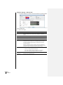
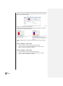
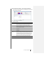
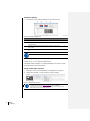
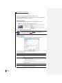
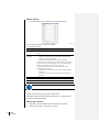
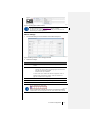
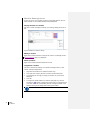
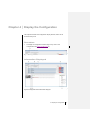
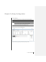
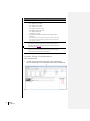
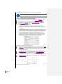
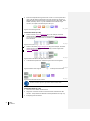
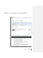
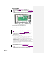
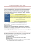
COM43
Configuration Software
for MX43 Controller
14 jun 2007
Control version No 2
User Manual
P/N: NPCOM43EN
Revision: A
Copyright © 2011 by OLDHAM
Edition: November 2011
All rights reserved. The reproduction of this document without the written
permission of OLDHAM is forbidden.
The information contained in this manual is accurate to the best of our knowledge.
As a result of continuous research and development, t he specifications of this
product may be modified at any time without prior notice.
OLDHAM
ZI Est – Rue Orfila
BP 20417
62027 ARRAS – France
Tel.: +33 (0)3 21 60 80 80 - Fax: +33 (0)3 21 60 80 00
Website: www.oldhamgas.com
Table of contents
ii
Table of contents
Chapter 1 │General Information ................................................... 1
User Manual .................................................. Erreur ! Signet non défini.1
Symbols Used .......................................................................................... 1
Important Information ..................................... Erreur ! Signet non défini.1
Liability Limits ................................................ Erreur ! Signet non défini.2
Chapter 2 │General Introduction ..................................................... 3
Purpose of the COM43 application ............................................................ 3
Install the COM43 application ................................................................... 3
Start the COM43 application ..................................................................... 3
Chapter 3 │Create a Configuration ................................................. 5
Object ...................................................................................................... 5
Procedure ................................................................................................ 5
Create/Select a Configuration ................................................................... 5
Configuration Window ............................................................................ 65
Create a New Configuration ...................................................................... 7
Add Modules ............................................................................................ 9
Add a Detector ......................................................................................... 9
Add a 4- or 8-Relay Module .................................................................... 14
Add a 4-Analog-Output Module ............................................................... 16
Add a 16-Logic-Input Module .................................................................. 17
Add an 8-Analog-Input Module ................................................................ 18
Module Management .............................................................................. 20
Chapter 4 │Display the Configuration ........................................... 21
Procedure .............................................................................................. 21
Information Displayed ............................................................................. 21
Chapter 5 │Relay Configuration ............. Erreur ! Signet non défini.23
Procedure .............................................................................................. 23
Overview of the Window ......................................................................... 23
Access Relay Configuration .................................................................... 24
Program without the Function Editor ....................................................... 26
Program with the Function Editor ............................................................ 27
Function Creation Example ..................................................................... 29
Table of contents
iii
Chapter 6 │Configure Analog Outputs.......................................... 33
Object .................................................................................................... 33
Overview of the Window ......................................................................... 33
Output Configuration .............................................................................. 34
Chapter 7 │Data Transfer .............................................................. 35
Object .................................................................................................... 35
PC to MX43 Data Transfer ...................................................................... 35
MX43 to PC Data Transfer ...................................................................... 36
Chapter 8 │Index ............................................................................ 37
iv
COM43
User Manual
Chapter 1 │ General Information
User Manual
These instructions must be read and understood to ensure correct use of the
application, otherwise the safety of the installation could be jeopardized.
Studying the User Manual for the MX43 Controller (P/N NPM43xx) is also
recommended. This can be downloaded from our website
www.oldhamgas.com.
The information and technical data contained in this manual are based on the
information that is available at a given time. In case of doubt, contact Industrial
Scientific Oldham (referred to subsequently as Oldham) for additional
information.
The aim of this manual is to supply simple and accurate information to the
user. Oldham cannot be held liable for any misinterpretations in the reading of
this manual. In spite of our efforts to produce an error-free manual, it may
nonetheless contain some unintentional technical inaccuracies.
In the client’s interest, Oldham reserves the right to modify the technical
characteristics of its equipment to increase their performance without prior
notice.
The present instructions and their content are the inalienable property of
Oldham.
Symbols Used
Icon
Significance
This symbol indicates useful additional information.
Important Information
The COM43 application covered by this manual gives the operator total
freedom in configuring the MX43 controller. Coherency checks of the input
values and/or related actions are not conducted by the application. It is the
operator's responsibility to check the configuration file’s coherency. The next
section Liability Limits defines this limitation.
1 - General Information
1
Liability Limits
Neither Oldham nor any other associated company may under any
circumstances be held liable for any damage, including, without limitation,
damage due to loss or interruption of manufacture, loss of information, defect
in the COM43 application and/or MX43 controller configured using this
application, injuries, loss of time, financial or material loss, or any direct or
indirect consequence of loss occurring in the context of the use or impossibility
of use of the product, even where Oldham has been informed of such damage.
2
COM43
User Manual
Chapter 2 │ General Introduction
Purpose of the COM43 application
The COM43 application must be installed on a PC running Windows XP,
Windows Vista or Windows 7 (32- or 64 bit).
COM43 is the programming interface for the MX43 controller. COM43 enables
the configuration file of an MX43 controller to be read or a configuration file to
be written to an MX43.
The configuration file is transferred via USB.
002
Figure 1: The COM43 application allows MX43 configuration on a PC as well as
bidirectional transfer of the configuration file via USB
Install the COM43 application
Follow the steps below:
■
Insert the CD-ROM in the drive of the PC on which the COM43
application is to be installed.
■
If installation does not start automatically, double-click the COM43.exe
icon.
■
Select the application language and click OK.
■
In the Welcome to the wizard window, click Next and follow the steps.
■
Once installation is complete, the COM43 Installation Complete window is
displayed.
■
Click Finish and the application will start automatically.
Start the COM43 application
By default, the COM43 application is started from the Start menu > COM43 or
by double-clicking the COM43 icon on the desktop, if that option was selected
during installation of the COM43 application.
2 - General Introduction
3
4
COM43
User Manual
Chapter 3 │Create a Configuration
Object
The purpose of this chapter is to describe the various modules (detectors,
relays, analog inputs, analog outputs, logic inputs) that are part of the
detection installation.
At this stage, USB connection between the PC on which the COM43 application is
installed and the MX43 is not necessary. The configuration file (xxx.cfg) will be saved
(PC hard disk, USB key or network drive) to be accessed at a later stage for
modification, duplication or transfer to the MX43 to be set up.
A configuration file can be created in several stages by reloading it (File > Open). A
configuration file can also be copied and modified so that it can be used with another
MX43 (File > Open and File > Save as).
Procedure
Program the MX43 by following the steps described below.
Step
1
2
3
Action to be performed
Page
Create a new configuration.
7
Or reload an existing configuration.
5
Add modules:
9
- Detector.
9
- 4- or 8-relay module.
14
- 4-analog-output module.
15
- 16–logic-input module.
17
- 8-analog-input module.
18
Display, modify, delete, copy/paste a module.
20
Create/Select a Configuration
■
To create a new configuration, go directly to the section Create a New
Configuration on page 7.
■
To reload a saved configuration, select the configuration file to be used
(cfg extension) from File > Open before moving on to the next paragraph.
3 - Create a Configuration
5
Configuration Window
The figure below shows an example of a configuration window.
CONF_00
Figure 2: COM43, screenshot of the General settings menu
Ref.
A
Information
Page
General settings (Controller name, Number of lines, etc.).
Erreu
r!
Signe
t non
défini.
7
B
Definition of the lines type (off, digital, 4-20 mA).
7
C
RS485 output settings.
8
D
Resources area showing free slots (modules, detectors, relays, inputs,
outputs).
8
E
Module icons:
Detector correctly configured.
9
Detector incorrectly configured, generally not assigned to an LED
bar (see page Erreur ! Signet non défini.10).
9
4- or 8-relay module.
14
4-analog-output module.
15
16-logic-input module.
17
8-analog-input module.
F
6
COM43
User Manual
Information on the module selected.
18
20
Create a New Configuration
When COM43 starts, the General settings tab is active (Figure 2Figure 2).
Controller settings
This information concerns the controller (Figure 2Figure 2, A):
Label
Information
Controller name
Defines the name (15 characters maximum) that will be displayed on the
MX43 start-up and sleep screens as well as in the System info submenu.
Language
Select the language to be used by the controller.
Password (level 1)
Enter the password for accessing the Calibration menu (1000 by
default).
Password (level 2)
Enter the password for accessing the Settings, Calibration and
Maintenance menus (1000 by default). This also protects against data
being deleted from the Information menu.
Enable on-board
buzzer
Check to enable on-board buzzer when a fault and/or alarm occurs.
Warming-up
Defines the delay (0 to 300 seconds) during which the alarm relays are
inhibited after powering up the MX43.
Number of lines
Select the controller version (4 or 8 lines option).
If the 8 lines option is selected, this cannot be changed to
the 4 lines option. If an error is made, create a new file (File
> New) without saving the current file.
Lines type settings
This information concerns the activation and definition of the lines type (Figure
3Figure 3, A).
Label
Information
Line 1
Select the line type.
Lines 2 to 4 (or 8)
-
OFF: line not in use.
-
Digital: all line modules will be digital.
-
4-20 mA: the line will be connected to a 4-20 mA analog transmitter.
Define the other lines in the same way as Line 1.
The Configuration map graphic area is updated as the line type is defined
(Figure 3, D).
Although 32 addresses are represented for each line, the MX43 supports up
to 16 modules in its 4-line version and 32 modules in its 8-line version.
3 - Create a Configuration
7
Commentaire [SC1]: The French
translates literally as "This information
concerns", which seems strange in view
of the phrasing used in subsequent
paragraphs. It has therefore been
assumed that the French should read
"Ces informations concernent la
centrale".
CONF_02
Figure 3: The Configuration map area (B) displays the choices made in the Lines type area
(A)
Ref.
Information
A
Line settings.
B
Graphic display of the current configuration. In this example, line 4 is not declared
(OFF).
C
Example of a 4-20 mA analog line. Only an analog transmitter can be assigned to this
line.
D
Example of a digital line. Up to 32 digital modules can be connected to this line.
RS485 digital output settings
This information concerns the MX43 RS485 output (Figure 2Figure 2, C).
Label
Information
Baud Rate
Select transfer rate. 9600 baud by default.
Even/Odd
Select parity. No parity by default.
Stop
Select number of Stop bits. 1 Stop bit by default.
Modbus slave
number
Assign slave number (between 1 and 255) of the MX43.
0 by default.
MX43 capacity
This area displays the number of registered modules and their representation
as a percentage of the maximum capacity. See page 21 for more details.
It is advisable to save the configuration via File > Save or File > Save as.
8
COM43
User Manual
Add Modules
Having configured the lines, modules can now be added to each one.
The MX43 capacity graphic area constantly shows how many modules are
available.
Refer to the pages indicated for the type of module to be added.
Type of module to be added
See page
Detector
9
4- or 8-relay module
14
4-analog-output module
15
16-logic-input module
17
8-analog-input module
18
Modify a module
20
Delete a module
20
Copy a module
20
Add a Detector
Detectors can be analog (4-20 mA) or digital. Follow the steps below for each
detector.
Type of detector selection
1.
Right-click the block where a detector is to be added (1 to 32 for a digital
line, 1 for an analog line).
2.
Select (Figure 4Figure 4) Add a module > Detector or Add a detector
depending on whether the line is digital or analog.
3.
Select the detector type.
4.
Select the gas to be detected.
CONF_50_01
Figure 4: Detector selection
If the COM43 application refuses to add a module, check the available capacity in
the MX43 capacity area (see Figure 2Figure 2, page 6 for details).
3 - Create a Configuration
9
Detector settings – Detector tab
1.
The window displays the Detector tab with the detector’s general settings.
CONF_50_02
Figure 5: Detector tab
2.
Define the settings.
Label
Information
Name
Enter the detector name (15 characters maximum): for example, the
detector’s location. This information will be displayed on the MX43
screen.
Type
Select the detector type from the drop-down list.
Gas
Select the gas to be detected from the drop-down list.
Range
Select the measurement scale and display unit.
Hysteresis
Define the alarm hysteresis. This value can be set from 0 to 3% of the
measurement range in steps of 1%. A hysteresis prevents the alarm
from being repeatedly triggered when the measurement fluctuates
around the set point.
Example: a hysteresis of 3% for a range of 100 ppm is equivalent to
3 ppm. If the alarm threshold is set at 50 ppm, acknowledgment will be
permitted at a gas concentration less than or equal to 47 ppm.
Average display
LED bar
assignment
10
COM43
User Manual
Option to display the average measurement value on the MX43 screen:
-
Inactive: no average calculation displayed.
-
Over 15 min.: displays average calculation over 15 minutes.
-
Over 8 hours: displays average calculation over 8 hours.
Click one of the buttons located under the LED bars to assign the
detector to the corresponding area.
Alarm 1 settings – Alarm 1 tab
1.
Click the Alarm 1 tab to set the first alarm threshold.
CONF_50_03
Figure 6: Alarm 1 tab
2.
Define the settings.
Label
Information
Acknowledgment
Alarm 1 acknowledgment mode.
-
Manual: the alarm is acknowledged manually by the operator; this
can only occur once the alarm event has disappeared.
-
Automatic: the alarm is acknowledged automatically as soon as the
alarm event disappears.
Trigger
Alarm trigger type:
-
Rising edge: the alarm is triggered as soon as the monitored value
rises above the Instantaneous or Averaged alarm threshold (see
following points).
-
Falling edge: the alarm is triggered as soon as the monitored value
falls below the Instantaneous or Averaged alarm threshold (see
following points). This option is used to measure oxygen, for
example.
Instantaneous
Management of the instantaneous alarm. This becomes active as soon
as the Enabled box is checked. Then set the alarm threshold using the
slider.
Averaged
Management of the averaged alarm. This becomes active as soon as the
Enabled box is checked. Set the averaged alarm threshold using the first
slider and the averaging time using the second slider (duration from 15
to 480 minutes). This value is used only to trigger the relay and has no
effect on the average values displayed.
The alarm event can follow either an Instantaneous alarm
or an Averaged alarm without distinction.
Other tabs
If necessary, refer to the Detector settings - Alarm 2 tab section before
closing this window by clicking OK.
Also refer to the Parameter display section on page 14 with regard to the
information displayed in the top part of the window.
OK
Close the window and save the changes.
Cancel
Close the window without saving the changes.
3 - Create a Configuration
11
At the same time, the barograph (A) displays the alarm threshold (red zone) in
relation to the scale range (blue zone) according to the position of the slider
(B) setting the alarm threshold.
CONF_50_04
Figure 7: Link between slider and barograph
Note that the red and blue zones are reversed when the alarm is said to be
increasing or decreasing (see Figure 8).
CONF_50_07
Increasing alarm set at 15% of the
measurement range.
CONF_50_08
Decreasing alarm set at 63% of the
measurement range (for an oxygen detector
with a range of 0-30% vol. and an alarm set at
19% vol.).
Figure 8: Barograph with an increasing alarm (left figure) and decreasing alarm (right
figure)
Alarm 2 settings – Alarm 2 tab
1.
Click the Alarm 2 tab to set the second alarm threshold.
2.
Enter or change the preset data as described for Alarm 1 (Alarm 1
settings – Alarm 1 tab section on page 11).
Alarm 3 settings – Alarm 3 tab
12
COM43
User Manual
1.
Click the Alarm 3 tab to set the third alarm threshold.
2.
Enter or change the preset data as described for Alarm 1 (Alarm 1
settings – Alarm 1 tab section on page 11).
Out of range alarm settings – Out of range and fault tab
1.
Click the Out of range and fault tab to set and display the overscale and
underscale alarm parameters.
CONF_50_05
Figure 9: Tab for setting out of range alarms
2.
Define the settings.
Label
Information
Overscale
Set the overscale alarm threshold (value can be set up to 110% of the
range). This function can also be regarded as a fourth alarm threshold.
Note that acknowledgment is manual and cannot be modified.
Underscale
Set the underscale alarm threshold (value can be set from 0 to -10% of
the range). This function is usually used for preventive maintenance to
report a negative shift in a detector.
Out of range
Non-configurable value of high fault (see MX43 manual for fault
management).
Fault
Non-configurable value of low fault (see MX43 manual for fault
management).
Non ambiguity
reading
Managing the Non ambiguity reading alarm applies only to explosive gas
OK
Close the window and save the changes made in all windows.
Cancel
Close the window without saving the changes.
detectors. On detecting a concentration of gas higher than 100% LEL,
the LCD display will indicate >100% LEL together with the message High
concentration. Reset by authorized person in maintenance menu . The
OVS and FAULT indicators are activated. The Non ambiguity reading
alarm can only be cleared by switching off the detector via the MX43
Maintenance menu once the gas level falls below this threshold.
3 - Create a Configuration
13
Parameter display
1.
This area (A to D) is visible regardless of which tab is active.
CONF_50_06
Figure 10: Parameters display area
Ref.
Information
See page
A
Type of detector and measurement range, defined in the Detector tab.
10
B
Barographs of the instantaneous alarms defined in the Alarm 1, Alarm 2
and Alarm 3 tabs.
11
C
Barographs of the averaged alarms defined in the Alarm 1, Alarm 2 and
Alarm 3 tabs.
12
D
Parameters of the various faults defined in the Out of range and fault
tab.
13
It is advisable to save the configuration via File > Save or File > Save as.
Add a 4- or 8-Relay Module
This digital module manages 4 or 8 relays depending on its version. Follow
the steps below for each relay module.
Relay module type selection
1.
Right-click on one of the dotted areas of the digital line in question.
2.
Select Add a module > 4-relay module (or 8-relay module).
CONF_60_01
Figure 11: Relay module selection
If the COM43 application refuses to add a module, check the available capacity in
the MX43 capacity area (see Figure 2Figure 2, page 6 for details).
The address of the module (see MX43 User Manual) must be identical to the
address defined using the COM43 application.
14
COM43
User Manual
Module settings
1.
The relay module settings can be entered in the window that opens.
CONF_60_02
Figure 12: Settings window for a 4-relay module
2.
Define the settings.
Label
Information
Module name
Enter the module name (15 characters maximum): for example, its
location.
Enabled relays
Select the relays (R1 to R4 or R1 to R8) that will be used in the
installation. By default, relay R1 is enabled.
-
Checked: the relay is enabled and can be programmed (see
page Erreur ! Signet non défini.23).
-
Unchecked: the relay is not in use.
In the area to the right, enter text (15 characters maximum) defining the
function of the relay, such as Rotating light.
Check all/uncheck all
Enable or disable all relays.
Enabled logic
inputs
Enable additional logic inputs (I1 and I2) of the relay module. These
inputs will be connected to dry contacts.
-
Checked: the input is enabled. The dry contact connected to this
input will be monitored by the MX43.
-
Unchecked: the input is disabled and will not be monitored.
In the area to the right, enter text (15 characters maximum) defining the
function of the input, such as Emergency stop. This information will be
displayed on the MX43 screen in the event of an alarm.
The Open option is used to define the input status under normal
operating conditions (no fault):
-
Checked: the dry contact connected to this input is closed during an
alarm (NO).
-
Unchecked: the dry contact connected to this input is open during an
alarm (NC).
OK
Close the window and save the changes.
Cancel
Close the window without saving the changes.
It is advisable to save the configuration via File > Save or File > Save as.
Relay settings
Configuring the relay modules is now complete, but the relay settings are not
yet defined. This step comes in the Relay Configuration chapter on page
3 - Create a Configuration
15
Erreur ! Signet non défini.23.
Add a 4-Analog-Output Module
This digital module provides 1 to 4 programmable 4-20 mA analog outputs.
Follow the steps below for each module.
Module selection
1.
Right-click one of the dotted areas of the digital line in question.
2.
Select Add a module > 4-analog-output module.
CONF_70_01
Figure 13: 4-analog-output module selection
If the COM43 application refuses to add a module, check the available capacity in
the MX43 capacity area (see Figure 2Figure 2, page 6 for details).
The address of the module (see MX43 User Manual) must be identical to the
address defined using the COM43 application.
Module settings
1.
The module settings can be entered in the window that opens.
CONF_70_02
Figure 14: Settings window for a 4-analog-output module
2.
Define the settings.
Label
Information
Module name
Enter the module name (15 characters maximum): for example, its
location.
Enabled outputs
Select the module outputs (O1 to O4) that will be used in the installation.
By default, output O1 is enabled.
-
Checked: the output is enabled and can be set (see page 41).
-
Unchecked: the output is not in use.
In the area to the right, enter text (15 characters maximum) defining the
function of the output.
16
COM43
User Manual
Check all/uncheck all
Enable or disable all outputs.
Enabled logic
inputs
Enable additional logic inputs (I1 and I2) of the relay module. These
inputs will be connected to dry contacts.
Label
Information
-
Checked: the input is enabled. The dry contact connected to this
input will be monitored by the MX43.
-
Unchecked: the input is disabled and will not be monitored.
In the area to the right, enter text (15 characters maximum) defining the
function of the input, such as Emergency stop. This information will be
displayed on the MX43 screen in the event of an alarm.
The Open option is used to define the input status under normal
operating conditions (no fault):
-
Checked: The dry contact connected to this input is closed during an
alarm (NO).
-
Unchecked: the dry contact connected to this input is open during an
alarm (NC).
OK
Close the window and save the changes.
Cancel
Close the window without saving the changes.
It is advisable to save the configuration via File > Save or File > Save as.
Output settings
Configuring the 4-analog-output modules is now complete, but the output
settings are not yet defined. This step comes in the Configure analog outputs
chapter on page 33.
Add a 16-Logic-Input Module
This digital module monitors 1 to 16 logic inputs.
Module type selection
1.
Right-click one of the dotted areas of the digital line in question.
2.
Select Add a module > 16-logic-input module.
CONF_80_01
Figure 15: 16-logic-input module selection
If the COM43 application refuses to add a module, check the available capacity in
the MX43 capacity area (see Figure 2Figure 2, page 6 for details).
The address of the module (see MX43 User Manual) must be identical to the
address defined using the COM43 application.
3 - Create a Configuration
17
Module settings
1.
The module settings can be entered in the window that opens.
CONF_80_02
Figure 16: Settings window for a 16-logic-input module
2.
Define the settings.
Label
Information
Module name
Enter the module name (15 characters maximum): for example, its
location.
Enabled inputs
(IL1 to IL16)
Enable module inputs (IL1 to IL16).
-
Checked: the input is enabled. The dry contact connected to this
input will be monitored by the MX43.
-
Unchecked: the input is disabled and will not be monitored.
In the area to the right, enter text (16 characters maximum) defining the
function of the input, such as Emergency stop. This information will be
displayed on the MX43 screen in the event of an alarm.
The Open option is used to define the input status under normal
operating conditions (no fault):
-
Checked: the dry contact connected to this input is closed during an
alarm (NO).
-
Unchecked: the dry contact connected to this input is open during an
alarm (NC).
Check all/uncheck all
Enable or disable all logic inputs.
OK
Close the window and save the changes.
Cancel
Close the window without saving the changes.
It is advisable to save the configuration via File > Save or File > Save as.
Add an 8-Analog-Input Module
This digital module retrieves the measurements from 1 to 8 analog inputs
(4-20 mA or Wheatstone bridge).
Module type selection
18
COM43
User Manual
1.
Right-click one of the dotted areas of the digital line in question.
2.
Select Add a module > 8-analog-input module.
CONF_90_01
Figure 17: 8-analog-input module selection
If the COM43 application refuses to add a module, check the available capacity in
the MX43 capacity area (see Figure 2Figure 2, page 6 for details).
The address of the module (see MX43 User Manual) must be identical to the
defined using the COM43 application.
Module settings
1.
The module settings can be entered in the window that opens.
CONF_90_02
Figure 18: Settings window for an 8 analog-input module
2.
Define the settings.
Label
Information
Module name
Enter the module name (15 characters maximum): for example, its
location.
Inputs 1 to 8
Enable the inputs that will be used in the installation.
-
Checked: the input is enabled. The analog signal connected to this
input will be monitored by the MX43.
-
Unchecked: the input is disabled.
As soon as the input is enabled, the detector configuration screen is
displayed. Refer to the Detector settings - Detector tab section on
page 10 for details of the configuration.
OK
Close the window and save the changes.
Cancel
Close the window without saving the changes.
Note that adding this module automatically reserves 8 slots in the measurement
line, as displayed in the figure below.
CONF_xxxxx
Figure 19: Automatic reservation of 8 slots for an 8-analog-input module
It is advisable to save the configuration via File > Save menu or File > Save as.
3 - Create a Configuration
19
Module Management
As soon as one or more modules of each type have been defined, each of
these modules can be modified, deleted and copied/pasted.
Display the data of a module
Left-click a module to display its settings. Any missing settings are shown in
red.
CONF_04
Figure 20: Example of a module’s settings
Modify a module
Right-click a module and select Configure the module. The settings window
(Figure 5Figure 5, page 10) is displayed.
Delete a module
Right-click a module and select Delete the module.
Copy/Paste a module
This action retrieves the settings of a module and assigns them to a new
module. Follow the steps below:
1.
Right-click the module to be copied and select Copy.
2.
Then right-click an empty block of an active line and select Paste.
3.
The message Do not forget to assign your detector to an LED bar is
displayed.
4.
Click OK.
5.
To assign the copied module to an LED bar (see page 10), click the
crossed icon ( ), select Configure the module and, in the Assignment of
a bar area, select the corresponding LED bar. Change the Name of the
detector and any other settings before closing the window.
It is advisable to save the configuration via File > Save or File > Save as.
20
COM43
User Manual
Chapter 4 │ Display the Configuration
This chapter describes the configuration display window, which can be
accessed at any time.
Procedure
1.
To display the configuration window (Figure 27), click on the
Configuration tab (Figure 21Figure 21, A).
ARC_00
Figure 21: Configuration tab
Information Displayed
ARC_01
Figure 22: Configuration tab and information displayed
4 - Display the Configuration
21
Ref.
A
Information
Drop-down list for selecting the lines to be displayed in (C).
- All lines: displays in area (C) all the lines and associated modules. Additional sorting
is possible using the button (B).
- Line xx: displays in area (C) line number xx and associated modules.
B
Additional buttons for the drop-down list (A).
- Display all addresses: displays in area (C) all the lines.
- Display configured lines only: displays in area (C) only the configured lines.
C
Details of the lines based on choices (A) and (B).
- Blue lines: digital modules.
- Gray lines: analog modules.
The information displayed is:
- Address: module address in the form Line-Module.
- Label: module name.
- Type: module type.
D
Barograph showing the free slots (modules, detectors, relays, inputs, outputs).
Number of registered modules: total number of digital modules connected (up to 16 in
the case of a 4-line version MX43 or up to 32 in the case of the 8-line version).
Number of registered detectors: total number of detectors (digital or analog) connected
(up to 16 in the case of a 4-line version MX43 or up to 32 in the case of the 8-line
version).
Number of registered relays: total number of registered relays: at least 8 internal
relays + relay module relays (up to 16 in the case of a 4-line version MX43 or up to 32
in the case of the 8-line version).
Number of registered analog outputs: total number of registered analog output (up to
16 in the case of a 4-line version MX43 or up to 32 in the case of the 8-line version).
Number of registered logic inputs: total number of registered input inputs for all the
modules (up to 16 in the case of a 4-line version MX43 or up to 32 in the case of the
8-line version).
E
Number of lines. The number of lines displayed depends on the controller version and
filter applied (see A).
F
Display of a 4-20 mA analog line with a single block. The dotted area represents the
position of an analog module to be defined.
G
Display of a digital line with or without configured modules.
Detector correctly configured.
Detector incorrectly configured, generally due to the module not
having been assigned to the LED bar (see page Erreur ! Signet
non défini.10).
4-or 8-relay module.
4-analog-output module.
16-logic-input module.
8-analog-input module.
H
22
COM43
User Manual
Display of a module’s data by left-clicking on this module. The missing parameters are
shown in red.
Chapter 5 | Relay Configuration
Procedure
1.
Program the MX43 relays in accordance with the following table.
Step
Action to be performed
Page
1
Open the relay configuration window.
24
2
Program a simple logic command. Use this method if the command logic
uses only a single logic function OR, AND, VOTING, NOR or NAND.
26
Program an advanced logic command using the function editor. Use this
method if the command logic requires multiple logic functions.
27
Overview of the Window
REL_00
Figure 23: Main relay programming window, Relay settings matrix tab
5 - Relay Configuration
23
Ref.
Information
Page
A
List of configured events
9
B
Selection of events to be displayed in (A).
-
- AL1: displays Level 1 alarms.
- AL2: displays Level 2 alarms.
- AL3: displays Level 3 alarms.
- OVS: displays Overscale events.
- UDS: displays Underscale events.
- FLT: displays fault events.
- LI: displays Logic Inputs.
- Drop-down list: programming shortcut (D) for the relay output in
question (C).
First, select an event (A) or several events (A) using the CTRL or Shift keys.
Then select the function from this drop-down list and drag everything to the
relay output (E) in question.
C
List of internal outputs (relays 1 to 5 + integrated siren + integrated flash
at the MX43) and external outputs (relays of relay modules) made
available. Double-click a relay output to open the Relay configuration
24
window (Figure 25Figure 25).
D
Logic function assigned to each relay (OR, NOR, AND, NAND, Voting or
24
Advanced Function (combination of logic functions that can only be
carried out with the function editor; see page 27)).
Access Relay Configuration
Follow the steps below:
1.
In the list of relays, double-click the relay to be programmed (A).
NB: The Default relay is non-configurable and cannot be programmed.
REL_SE_00
Figure 24: Information displayed in the Relay settings matrix tab
24
COM43
User Manual
2.
The Relay configuration window is displayed.
REL_SE_01
Figure 25: Relay configuration window
Ref.
Information
Pages
A
Selection of relay operation in Normal mode, as opposed to Buzzer
function mode (C).
26, 27
B
Relay name.
26, 27
C
Selection of relay operation in Buzzer function mode. To be used only if
26, 27
the selected relay controls an audible warning device.
D
Time lag definition.
26, 27
- Normal function: setting of the trigger delay.
26, 27
- Buzzer function: setting of the reset inhibit, automatic reset and
26, 27
reactivation time lags. See Figure 26Figure 26.
- De-energized: use of the positive safety function for internal relays
26, 27
only. For relay modules, programming is carried out manually using
the relay switch block.
E
Optional choice of the logic function to be applied between events (H) to
activate the selected relay (B).
26, 27
F
Access the function editor.
G
Selection criteria for events to be displayed in (H).
26, 27
27
H
List of usable events, possibly sorted by (G).
26, 27
J
Add the event selected in (H) to the command list (M) for the relay (B).
The drag and drop function also works here.
26, 27
K
Confirm the changes made in this window.
26, 27
L
Cancel the changes made in this window.
26, 27
M
Delete one or more events from the list (M) for the relay in question (B).
26, 27
5 - Relay Configuration
25
Program without the Function Editor
Use this method if the relay command logic needs only a single logic function OR,
AND, VOTING, NOR or NAND, for example (RL1+RL2+RL3).
Step 1: define the relay operating mode
1.
With the Relay configuration window open (Figure 25Figure 25), check
that the relay to be programmed is selected (Figure 25Figure 25, B).
2.
If necessary, sort the list of events (Figure 25Figure 25, H) using the
filters (Figure 25Figure 25, G).
3.
Select the relay operating mode:
-
Normal: a Normal relay can be reset only when the alarm event
disappears. A trigger delay of between 0 and 60 seconds (Figure 30, D)
can be set.
-
Buzzer function: a Buzzer relay can be reset even while the alarm event
is still in progress. This function allows the audible warning devices to be
switched off and must be used only for this purpose. Various time lag
options are possible after selecting this option (see figure below).
-
Positive safety: this option is available only after selecting an internal
relay (see MX43 manual). For those relays in relay modules, positive
safety is programmed manually using the relay switch block.
REL_SE_02
Figure 26: The Time lag in buzzer function area
-
Reset inhibit: minimum activation time between 0 and 15 minutes (Figure
27Figure 27, E). No manual reset (Figure 32, B) or automatic reset
(Figure 32, C) is authorized during this time. Reset is possible only when
the Reset inhibit ends.
-
Automatic reset: minimum relay activation time before automatic reset
(Figure 27Figure 27, C). The value of this time (Figure 27Figure 27, F)
must be greater than the Reset inhibit value (Figure 27Figure 27, E).
-
Reactivation time: time (Figure 32, G) after which the relay is reactivated
if the alarm event is still present. A new activation cycle is then launched
(Figure 27Figure 27, D).
REL_SE_03
Figure 27: Operation of the buzzer relay
26
COM43
User Manual
Ref.
Information
A
Start of the alarm activation cycle.
B
Manual reset, where applicable.
C
Automatic reset.
D
Start of a new alarm activation cycle triggered if the alarm event is still present.
E
Reset inhibit: minimum activation time between 0 and 15 minutes.
F
Minimum relay activation time before automatic reset must be greater than the Reset
inhibit value (E).
G
Time after which the relay is reactivated if the alarm event is still present.
Step 2: select the events and logic to be used
1.
For a single event acting on the relay: select the event (Figure 25Figure
25, H) and drag it to the Relay events list (Figure 25Figure 25, M) or click
the Add button (Figure 25Figure 25, J).
For several events acting on the relay: first select the logic function
(Figure 25Figure 25, E) and then the events (Figure 25Figure 25, H)
using the CTRL and/or Shift keys. Next drag them to the Relay events list
(M) or click the Add button (Figure 25Figure 25, J).
2.
To delete an event from the list (Figure 25Figure 25, M), select the event
and click Delete (Figure 25Figure 25, N).
3.
If necessary, view the function using the Function Editor (Figure 25Figure
25, F). Refer to the Program with the Function Editor section on page 27
for more details.
4.
Click Confirm (Figure 25Figure 25, K) to confirm the configuration or
Cancel (Figure 25Figure 25, L) to discard the changes made.
Step 3: confirm the settings
1.
The Relay output window in the Relay settings matrix tab shows any logic
function connected with the relay in question.
If necessary, double-click this line to open the Relay configuration window
again.
2.
If necessary, continue programming the other relays as described in the
Program without the Function Editor section on page 26.
Program with the Function Editor
Use this method if the relay command logic uses multiple logic functions, for
example [(RL1 OR RL2) AND (RL3 NOR RL4)].
Step 1: define the relay operating mode
1.
With the Relay configuration window open (Figure 25Figure 25), check
that the relay to be programmed is selected (Figure 25Figure 25, B).
2.
Select the relay operating mode (see Normal or Buzzer on page 26).
5 - Relay Configuration
27
Step 2: select the events and logic to be used
1.
Click the Function Editor button (Figure 25Figure 25, F).
2.
If necessary, sort the list of events displayed (Figure 28Figure 28, B)
using the filters (Figure 28Figure 28, A).
3.
Construct the logic function.
An example is given in the Function Creation Example section on page 29.
4.
Click OK to close the function editor and save the function created or
Cancel to discard the changes.
REL_AE_01
Figure 28: Function editor window
Ref.
A
Information
Checkboxes for sorting the events to be displayed in (B).
- AL1: displays Level 1 alarms.
- AL2: displays Level 2 alarms.
- AL3: displays Level 3 alarms.
- OVS: displays Overscale events.
- UDS: displays Underscale events.
- FLT: displays fault events.
- LI: displays Logic Inputs.
B
List of available events, possibly sorted by (A).
C
Level 1 logic function block.
NB: A logic function can be selected only if two events are assigned to the function
block. The Voting function requires at least three events.
REL_AE_02
Figure 29: The logic functions available in a block
28
COM43
User Manual
D
Button for adding a Level 1 logic block.
E
Level 2 logic function block usable only if a Level 1 block has been configured. Other
Ref.
Information
characteristics identical to block 1 (C).
F
Button for adding a Level 2 logic block.
G
Level 3 logic function block usable only if a Level 2 block has been configured. Other
characteristics identical to block 1 (C).
H
Button for adding a Level 3 logic block.
J
Level 4 logic function block usable only if a Level 3 block has been configured. Other
characteristics identical to block 1 (C).
K
Button for adding a Level 4 logic block.
L
Level 5 logic function block usable only if a Level 4 block has been configured. Other
characteristics identical to block 1 (C).
M
Name of relay receiving the logic of blocks 1 to 5.
N
Button for adding a Level 5 logic block.
O
List of available relays.
P
Confirms the configuration of the relay in question (M).
Q
Cancels any changes made and closes the window.
Comment on the limitations of the function editor
■
The function editor can manage 512 Level 1 logic blocks, 256 Level 2
logic blocks, 128 Level 3 logic blocks, 64 Level 4 logic blocks and 32
Level 5 logic blocks.
■
Each of the 6 alarms of each detector can intervene only 16 times in all
the Level 1 logic blocks.
■
Each of the 32 logic inputs can intervene only 16 times in all the Level 1
logic blocks.
■
Each Level 1, 2, 3 or 4 logic block can intervene only once in the higher
level logic blocks.
Function Creation Example
The example shows how the following logic function is created:
[(A OR B) AND (B OR C)] NAND [(E, F, G) (Voting 2/3)]
REL_AE_00A
Figure 30: The logic blocks after programming
Start the function editor
1.
Open the function editor by clicking the Function Editor button (Figure
25Figure 25, F).
5 - Relay Configuration
29
2.
Each block represents a logic level from Level 1 to Level 5 (from left to
right). The last block corresponds to the relay to which the function is
assigned. Each logic block carries out a logic function (OR, NOR, AND,
NAND, VOTING). As the = symbol indicates a level without a logic
function, the output is therefore equal to its input.
REL_AE_00B
Figure 31: The initial logic blocks
Create the block (A + B)
1.
Select an event (Figure 28Figure 28, B) (in the example, the event
referenced as A) and drag it to the first logic block (Figure 28Figure 28,
C). As soon as the mouse button is released, the event is displayed to the
left of the block.
REL_AE_04
Figure 32: The event is assigned to the first block
2.
Select a new event (Figure 28Figure 28, B) (in the example, the event
referenced as B) and drag it in the same way to the first logic block
(Figure 28Figure 28, C).
REL_AE_05
Figure 33: New event added to the input of the first block
3.
In the block drop-down list, select the logic function to be applied.
REL_AE_06
Figure 34: Selection of the logic function to be applied to the input of the first block
REL_AE_07
Figure 35: The first block has been created
To delete an event assigned to a block, right-click the event and select Delete.
Likewise, to delete a logic block, right-click the block and select Delete.
Create the block (C + D)
30
COM43
User Manual
1.
Click the Level 1 button to add a block.
2.
Drag each of the two events to this second block and select the OR
function. The procedure is identical to that explained for block (A + B).
3.
Everything looks as follows.
REL_AE_08
Figure 36: The two groups have been created
Create the AND function
1.
To create the AND function between (A + B) and (C + D), drag the Level
1 block (C + D) to the red Level 2 block.
2.
In the Level 2 block, select the AND function (see figure below).
REL_AE_09
Figure 37: The two groups are linked by the AND function
Create the Voting function
1.
To create the [(E, F, G) (Voting 2/3)] function, click the Level 1 button to
add a block.
2.
Drag at least three events to this block and select the Voting function and
the number of inputs that must be present (here 2 out of 3).
REL_AE_10
Figure 38: Selection of the Voting function and its levels
3.
Everything now looks as follows.
REL_AE_11
Figure 39: Creation of the Voting function (2 out of 3).
5 - Relay Configuration
31
Create the NAND function
The function editor only allows a block to be linked to a block of an
immediately higher level. This means that it is impossible to link the Level 1
Voting block to the Level 3 block (brown block). To overcome this restriction,
you can simply add a Level 2 block and use the logic function "=" (passing
block).
Follow the steps below.
1.
Click the Level 2 button to add a new block.
REL_AE_12
Figure 40: The Level 2 block attaches itself to the free Level 1 block.
2.
Drag the Level 1 block to the Level 2 block to create the link.
3.
Then drag the Level 2 block to the Level 3 block (brown block) to create
the link and then select the NAND function.
REL_AE_13
Figure 41: The two Level 2 blocks are linked to the Level 3 block by the NAND function
Completion
The required function [(A + B) x (B + C)] NAND [(E, F, G) (Voting 2/3)] has
been created. Click the OK button to confirm and close the window.
32
COM43
User Manual
Chapter 6 │Configure Analog Outputs
Object
Program the 4-20 mA outputs of the 4-20 mA output modules on the digital
lines.
Overview of the Window
The example below shows the configuration window for the analog outputs.
SA_01
Figure 42: The information displayed in the Analog output settings matrix tab
Ref.
A
Information
Page
Selection of function to be applied.
- Min: the value of the output current is equal to the lowest
measurement of a group of detectors (B).
- Max: the value of the output current is equal to the highest
measurement of a group of detectors (B).
- Average: the value of the output current is equal to the average
measurement of a group of detectors (B).
- Actual value: the value of the output current is identical to the signal
from a single detector (B).
NB: when using the Min, Max and Average functions, it is essential that
the detectors selected within a group are identical (same gas, same
measurement range, etc.).
6 - Configure Analog Outputs
33
Ref.
Information
B
List of available detectors.
C
Tab for configuring the 4-20 mA outputs covered by this chapter.
D
List of the 4-20 mA outputs and their associated function. If no function is
shown, this indicates that the output has not been configured.
Page
Double-click an output line to display the configuration details. See
Figure 43Figure 43.
E
Displays the characteristics of the 4-20 mA 4-analog-output module
selected by the user (E).
To delete a function, right-click the corresponding output and select Delete. To
modify a function, you must first delete it and then recreate it.
Output Configuration
Follow the steps below:
1.
Having selected the Analog output settings matrix tab (Figure 42Figure
42, C), choose from the drop-down list (Figure 42Figure 42, A) the
mathematical function to be used (Min, Max, Average or Actual value).
2.
Using the mouse, and the CTRL or Shift keys if required, select one or
more detectors (Figure 42Figure 42, B) and then drag them to the target
4-20 mA output (Figure 42Figure 42, D). The mathematical function used
is updated (Figure 42Figure 42, D, Function column).
3.
To access the configuration of an analog output, double-click the
corresponding output (Figure 42Figure 42, D).
The Add and Delete buttons allow you to add or delete detectors in the
list of Selected detectors (D). Note that it is not possible to modify the
function (C) from this screen.
SA_03
Figure 43: Detailed information on an output
4.
Click Confirm (F) to close the window and save any changes made.
5.
The outputs of the 4-20 mA output module(s) have been configured.
It is advisable to save the configuration via File > Save or File > Save as.
34
COM43
User Manual
Mis en forme : Vérifier l'orthographe
et la grammaire
Chapter 7 │Data Transfer
This chapter discusses the transfer of configuration data between the MX43
and the PC on which the COM43 application is installed.
Object
By the end of this chapter, the user will know how to transfer the configuration
file created in the previous chapters to an MX43 and also how to transfer the
configuration data from an MX43 to a PC so that it can be saved or modified.
PC to MX43 Data Transfer
Configuration check
1.
Start the COM43 application and display the corresponding configuration
file (.cfg extension) via File > Open.
2.
In the menu bar, select File > Configuration check.
3.
The message Configuration Check OK in the Configuration check window
indicates that the configuration is correct and that it can be transferred to
the MX43. If one or more notifications appear, correct the missing or
incomplete elements before continuing.
Connect the MX43
1.
Connect the PC to the programming port of the MX43 (Figure 44Figure
44, A) using a USB cable.
2.
Move the programming selector (Figure 44Figure 44, B) to position "1".
3.
Press the Reset button (Figure 44Figure 44, C) on the microcontroller.
The MX43 switches to standby. The configuration file can now be
transferred to the MX43.
During the transfer phases, the MX43 controller is not operational. Detection is no
longer assured.
Transfer the configuration file
1.
In the menu of the COM43 application, select Transfer > PC to MX43.
2.
In the window that opens, click Transfer.
3.
At the end of the transfer, the COM43 application displays Transfer
successful.
7 - Data Transfer
35
Disconnect the MX43
1.
Return the selector (Figure 44Figure 44, B) to position "0".
2.
Remove the USB cable between the PC and the MX43 (Figure 44Figure
44, A).
3.
The MX43 screen displays Configuration update accepted, and then the
MX43 restarts normally and launches an initialization cycle.
03
Figure 44: The elements used to connect an MX43 and a PC
MX43 to PC Data Transfer
Connect the MX43
1.
Connect the PC to the programming port of the MX43 (Figure 44Figure
44, A) using a USB cable.
2.
Move the MX43 selector to position "1" (Figure 44Figure 44, B).
3.
Press the Reset button (Figure 44Figure 44, C) on the microcontroller.
The MX43 switches to standby. The configuration file can now be
transferred to the PC.
Transfer the configuration file
1.
In the menu of the COM43 application, select Transfer > MX43 to PC.
2.
In the window that opens, select the destination folder for the
configuration file, and then click Transfer. By default, the filename is in
the following format: YYYYMMDDHHMMSS.cfg (year, month, day, hours,
minutes and seconds).
3.
At the end of the transfer, the COM43 application displays Transfer
successful. Click OK. The data from the configuration file transferred are
displayed on the PC screen.
Disconnect the MX43
36
COM43
User Manual
1.
Return the selector to position "0" (Figure 44Figure 44, B).
2.
Remove the USB cable between the PC and the MX43 (Figure 44Figure
44, A).
3.
The MX43 restarts normally and launches an initialization cycle.
Mis en forme : Français (France)
Chapter 8 │Index
4-20 mA outputs
Configuration, 33
A
Alarm
Event, 24
On-board buzzer, 7
Analog input
Settings, 18
Analog input module
Settings, 18
Analog output
Settings, 16
Analog output module
Configure, 33
Settings, 16
Assignment of a bar, 10
Average display, 10
Average (display), 10
Settings, 10
Digital output
Settings, 8
Display modules, 20
Display the configuration, 21
F
Fault alarm
Settings, 13
Function
Buzzer, 26
Buzzer lag, 26
Function editor
Limitations, 29
Program, 27
G
General introduction, 3
B
H
Bar (assignment), 10
Buzzer
Relay, 25
Buzzer function, 25
Buzzer lag, 26
Hysteresis, 10
C
Configuration
4-20 mA outputs, 33
Display, 21
Configuration check, 35
Configure
4-20 mA outputs, 33
Relays, 23
Copy modules, 20
D
Data
Transfer, 35
Delete modules, 20
Detector
Alarms, 11
L
Language, 7
Liability limits, 2
Line type
Settings, 7
Logic input
Event, 24
Settings, 17
Logic input module
Settings, 17
Logic inputs, 15
M
Message
Configuration check, 35
Modify modules, 20
Module
Copy, 20
Delete, 20
Display, 20
Modify, 20
8 - Index
37
Paste, 20
N
Non ambiguity reading, 13
O
Overscale, 13
P
Paste modules, 20
Positive safety, 26
Program with the function editor, 27
R
Relay module
Settings, 14
Relays
Buzzer, 25
Buzzer lag, 26
Buzzer operation, 26
Configure, 23
Normal operation, 26
RS485
Settings, 8
38
COM43
User Manual
S
Settings
Alarms, 11
Analog input module, 18
Analog input, 18
Analog output module, 16
Analog output, 16
Detector, 10
Fault alarm, 13
Line type, 7
Logic input module, 17
Logic input, 17
Relay module, 14
RS485, 8
RS485 digital output, 8
T
Transfer
MX43 to PC, 36
MX43-PC, 35
PC to MX43, 35
U
Underscale, 13
We guarantee:
1
Plus Points
Through our customer service department, to respond quickly and efficiently to your needs for advice or
order tracking anywhere in the world.
To respond as quickly as possible to all technical questions.
2 Quality
To ensure the highest quality products and services in accordance with the applicable international
standards and instructions.
3 Inspection and Reliability
To provide you with reliable equipment. The quality of our production is an essential condition for this
reliability. This is guaranteed by very stringent checks that are carried out from the arrival of raw
materials, all the way through manufacture and at the end of manufacture (all equipment dispatched is
configured to your individual requirements).
4 Commissioning
On request, to commission your equipment using our Ism-ATEX qualified engineers. An extra safety
guarantee.
5 Training
To provide targeted training.
6 Project department
Our team will study all your gas and flame detection projects through on-site inspections or based on
drawings. We can even offer preliminary design, design, installation and maintenance services for safety
systems in ATEX or non-ATEX areas in accordance with the applicable standards.
7 Maintenance contract
To offer rolling maintenance contracts that are tailored to your needs in order to guarantee perfect
safety:
• One or more inspections per year, including consumables.
• Renewable by tacit agreement.
• Including setting of fixed or portable gas detectors, and inspection of control systems.
8 On-site repair
To quickly send out our After Sales Service engineers. This is possible due to our local hubs in France
and abroad.
9 Factory repair
To deal with any problems that cannot be solved on site by returning the equipment to the factory.
Teams of specialist engineers will be sent out to repair your equipment as quickly as possible, thereby
minimizing the downtime.
For all After Sales Service in France, contact us by email at [email protected] or by telephone on
0800-OLDHAM (0800 653 426).
OUR MISSION
To protect people at work.
To provide the highest quality and best customer service
at every opportunity.
EUROPEAN PLANT AND OFFICES
Z.I. Est – rue Orfila B.P. 20417 – 62027 ARRAS Cedex FRANCE
Tel.: 33 3 21 60 80 80 – Fax: 33 3 21 60 80 00
Website: http://www.oldhamgas.com
AMERICAS
ASIA PACIFIC
EUROPE
Tel. : +1 412 788 4353
Fax : +1 412 788 8353
[email protected]
Tel. : +65-6561-7377
Fax : +65-6561-7787
[email protected]
Tel. : +33 3 21 60 80 80
Fax : +33 3 21 60 80 00
[email protected]