1
23A-1
GROUP 23A
CONTENTS
GENERAL DESCRIPTION. . . . . . . . .
23A-3
AUTOMATIC TRANSAXLE
DIAGNOSIS . . . . . . . . . . . . . . . . . . . . 23A-14
LINE PRESSURE ADJUSTMENT. . . . . . . .
23A-40
DIAGNOSTIC TROUBLE CODE CHART . .
23A-40
SYMPTOM CHART . . . . . . . . . . . . . . . . . . .
23A-41
DIAGNOSTIC TROUBLE CODE
PROCEDURES . . . . . . . . . . . . . . . . . . . . . .
23A-42
DIAGNOSTIC TROUBLESHOOTING
FLOW . . . . . . . . . . . . . . . . . . . . . . . . . . . . .
23A-14
SYMPTOM PROCEDURES . . . . . . . . . . . . 23A-249
INTRODUCTION TO A/T DIAGNOSIS . . . .
23A-14
DATA LIST REFERENCE TABLE . . . . . . . . 23A-323
A/T DIAGNOSTIC TROUBLESHOOTING
STRATEGY. . . . . . . . . . . . . . . . . . . . . . . . .
23A-15
INVECS-II CANCEL COMMAND. . . . . . . . . 23A-329
A/T DIAGNOSTIC TROUBLE CODE
DIAGNOSIS . . . . . . . . . . . . . . . . . . . . . . . .
23A-15
PCM TERMINAL VOLTAGE REFERENCE CHART
FOR TRANSAXLE OPERATION . . . . . . . . 23A-329
FAIL-SAFE/BACKUP FUNCTION. . . . . . . .
23A-18
ROAD TEST . . . . . . . . . . . . . . . . . . . . . . . .
23A-19
TORQUE CONVERTER STALL TEST . . . .
23A-25
HYDRAULIC PRESSURE TESTS . . . . . . .
23A-26
HYDRAULIC CIRCUIT . . . . . . . . . . . . . . . .
23A-32
ACTUATOR TEST REFERENCE TABLE . . 23A-328
PCM TERMINAL RESISTANCE AND CONTINUITY
INSPECTION CHART . . . . . . . . . . . . . . . . . 23A-332
INSPECTION PROCEDURE USING AN
OSCILLOSCOPE . . . . . . . . . . . . . . . . . . . . 23A-333
Continued on next page
WARNINGS REGARDING SERVICING OF SUPPLEMENTAL RESTRAINT SYSTEM (SRS) EQUIPPED VEHICLES
WARNING
•
Improper service or maintenance of any component of the SRS, or any SRS-related component, can lead to
personal injury or death to service personnel (from inadvertent firing of the air bag) or to the driver and
passenger (from rendering the SRS inoperative).
• Service or maintenance of any SRS component or SRS-related component must be performed only at an
authorized MITSUBISHI dealer.
• MITSUBISHI dealer personnel must thoroughly review this manual, and especially its GROUP 52B - Supplemental
Restraint System (SRS) before beginning any service or maintenance of any component of the SRS or any SRSrelated component.
NOTE
The SRS includes the following components: SRS air bag control unit, SRS warning light, front impact sensors, air bag module,
clock spring, and interconnecting wiring. Other SRS-related components (that may have to be removed/installed in connection
with SRS service or maintenance) are indicated in the table of contents by an asterisk (*).
23A-2
A/T FAULTY OPERATION PREVENTION
MECHANISM DIAGNOSIS . . . . . . . . 23A-334
STOPLIGHT SWITCH CHECK . . . . . . . . . . 23A-353
INTRODUCTION TO A/T KEY INTERLOCK AND
SHIFT LOCK MECHANISMS . . . . . . . . . . . 23A-334
SELECT SWITCH CHECK . . . . . . . . . . . . . 23A-354
A/T KEY INTERLOCK AND SHIFT LOCK
MECHANISMS DIAGNOSTIC TROUBLESHOOTING
STRATEGY. . . . . . . . . . . . . . . . . . . . . . . . . 23A-334
SHIFT SWITCH (DOWN) CHECK. . . . . . . . 23A-354
SYMPTOM CHART. . . . . . . . . . . . . . . . . . . 23A-334
PRESSURE SWITCH CHECK . . . . . . . . . . 23A-354
SHIFT SWITCH (UP) CHECK . . . . . . . . . . . 23A-354
A/T CONTROL RELAY CHECK . . . . . . . . . 23A-354
SOLENOID VALVE CHECK . . . . . . . . . . . . 23A-354
SYMPTOM PROCEDURES . . . . . . . . . . . . 23A-334
SELECTOR LEVER OPERATION
CHECK . . . . . . . . . . . . . . . . . . . . . . . . . . . . 23A-356
SPECIAL TOOLS. . . . . . . . . . . . . . . . 23A-342
KEY INTERLOCK MECHANISM
CHECK . . . . . . . . . . . . . . . . . . . . . . . . . . . . 23A-356
ON-VEHICLE SERVICE. . . . . . . . . . . 23A-343
SHIFT LOCK MECHANISM CHECK . . . . . . 23A-357
A/T CONTROL COMPONENT LAYOUT . . 23A-343
TRANSAXLE CONTROL* . . . . . . . . . 23A-358
ESSENTIAL SERVICE . . . . . . . . . . . . . . . . 23A-346
REMOVAL AND INSTALLATION . . . . . . . . 23A-358
A/T FLUID CHECK . . . . . . . . . . . . . . . . . . . 23A-346
INSPECTION. . . . . . . . . . . . . . . . . . . . . . . . 23A-360
A/T FLUID REPLACEMENT . . . . . . . . . . . . 23A-347
DISASSEMBLY AND ASSEMBLY . . . . . . . 23A-361
FLUSHING COOLERS AND TUBES . . . . . 23A-349
INSPECTION. . . . . . . . . . . . . . . . . . . . . . . . 23A-363
OIL COOLER FLOW CHECK . . . . . . . . . . . 23A-350
THROTTLE POSITION SENSOR
ADJUSTMENT . . . . . . . . . . . . . . . . . . . . . . 23A-351
A/T KEY INTERLOCK AND SHIFT LOCK
MECHANISMS*. . . . . . . . . . . . . . . . . . 23A-363
PARK/NEUTRAL POSITION SWITCH
CONTINUITY CHECK. . . . . . . . . . . . . . . . . 23A-351
REMOVAL AND INSTALLATION . . . . . . . . 23A-363
PARK/NEUTRAL POSITION SWITCH AND
CONTROL CABLE ADJUSTMENT. . . . . . . 23A-352
AUTOMATIC TRANSAXLE CONTROL
COMPONENT CHECK . . . . . . . . . . . . . . . . 23A-353
INSPECTION. . . . . . . . . . . . . . . . . . . . . . . . 23A-365
TRANSAXLE ASSEMBLY . . . . . . . . . 23A-366
REMOVAL AND INSTALLATION . . . . . . . . 23A-366
CRANKSHAFT POSITION SENSOR
CHECK . . . . . . . . . . . . . . . . . . . . . . . . . . . . 23A-353
SPECIFICATIONS . . . . . . . . . . . . . . . 23A-374
THROTTLE POSITION SENSOR
CHECK . . . . . . . . . . . . . . . . . . . . . . . . . . . . 23A-353
FASTENER TIGHTENING
SPECIFICATIONS. . . . . . . . . . . . . . . . . . . . 23A-374
A/T FLUID TEMPERATURE SENSOR
CONTINUITY CHECK. . . . . . . . . . . . . . . . . 23A-353
SERVICE SPECIFICATIONS . . . . . . . . . . . 23A-375
PARK/NEUTRAL POSITION SWITCH
CHECK . . . . . . . . . . . . . . . . . . . . . . . . . . . . 23A-353
LUBRICANTS . . . . . . . . . . . . . . . . . . . . . . . 23A-375
23A-3
AUTOMATIC TRANSAXLE
GENERAL DESCRIPTION
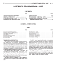
GENERAL DESCRIPTION
.
M1231000100173
The A/T come in two models, namely, F4A42 and F4A51.
ITEMS
SPECIFICATIONS
Transaxle model
F4A42-2-JZB7
F4A51-2-FZB2
F4A51-2-LZP
Engine model
4G64 (2.4L Engine)
6G72 (3.0L Engine)
<Vehicles without
variable induction
system>
6G72 (3.0L Engine)
<Vehicles with
variable induction
system>
Torque
converter
Type
3-element, 1-stage, 2-phase
Torque converter clutch
Provided (3rd to 4th)
Stall torque ratio
1.85
2.04
2.04
Transaxle type
4-speed forward, 1-speed reverse fully automatic
Gear ratio
1st
2.842
2.842
2.666
2nd
1.529
1.495
1.448
3rd
1.000
1.000
1.000
4th
0.712
0.731
0.731
Reverse
2.480
2.720
2.720
Final gear ratio (Differential gear ratio) 4.042
3.728
4.011
4
4
Number of underdrive clutch discs
4
Number of overdrive clutch discs
4
Number of reverse clutch discs
2
Number of low-reverse brake discs
6
Number of second brake discs
3
Manual control type
P-R-N-D-3-2-L (7
P-R-N-D (4 positions) + sport mode (up,
positions) or P-R-N-D down)
(4 positions) + sport
mode (up, down)
Shift pattern control
Electronic control (INVECS-II)
Oil pressure control during shifting
Electronic control (each oil pressure independently controlled)
Torque converter clutch control
Electronic control
TSB Revision
23A-4
AUTOMATIC TRANSAXLE
GENERAL DESCRIPTION
TRANSAXLE
The transaxle is made up of the torque converter and gear train. A 3-element, 1-step, 2-phase torque converter with built-in torque converter clutch is used. The gear train is made up of three sets of multi-plate
clutches, two sets of multi-plate brakes, one set of one-way clutches and two sets of planetary gears. The
planetary gears are made up of sun gears, carriers, pinion gears and annulus gears.
.
TRANSAXLE CONFIGURATION DRAWING
REV
2ND LR
OD
OWC
UD
AC001813 AB
.
COMPONENTS AND FUNCTIONS
COMPONENT
FUNCTION
Underdrive clutch
UD
connects the input shaft to the underdrive sun gear.
Reverse clutch
REV
connects the input shaft to the reverse sun gear.
Overdrive clutch
OD
connects the input shaft to the overdrive planetary carrier.
Low-reverse brake
LR
holds the low-reverse annulus gear and the overdrive planetary
carrier.
Second brake
2ND
holds the reverse sun gear.
One-way clutch
OWC
restricts the rotation direction of the low-reverse annulus gear.
FUNCTION ELEMENT TABLE
<Vehicles without sport mode>
OPERATING ELEMENT
SELECTOR LEVER
POSITION
ENGINE
START
PARKING
MECHANISM
UNDERDRIV
E CLUTCH
(UD)
REVERSE
CLUTCH
(REV)
OVER-DRIVE LOWCLUTCH (OD) REVERSE
BRAKE (LR)
SECOND
BRAKE (2ND)
P
Parking
OK
×
−
−
−
×
−
R
Reverse
−
−
−
×
−
×
−
N
Neutral
OK
−
−
−
−
×
−
D
1st
−
−
×
−
−
×*
−
D
2nd
−
−
×
−
−
−
×
D
3rd
−
−
×
−
×
−
−
D
4th
−
−
−
−
×
−
×
TSB Revision
23A-5
AUTOMATIC TRANSAXLE
GENERAL DESCRIPTION
OPERATING ELEMENT
SELECTOR LEVER
POSITION
ENGINE
START
PARKING
MECHANISM
UNDERDRIV
E CLUTCH
(UD)
REVERSE
CLUTCH
(REV)
OVER-DRIVE LOWCLUTCH (OD) REVERSE
BRAKE (LR)
SECOND
BRAKE (2ND)
3
1st
−
−
×
−
−
×*
−
3
2nd
−
−
×
−
−
−
×
3
3rd
−
−
×
−
×
−
−
2
1st
−
−
×
−
−
×*
−
2
2nd
−
−
×
−
−
−
×
L
1st
−
−
×
−
−
×
−
×: Function element
NOTE: * operates only when the vehicle is stationary [at approximately 10 km/h (6.2 mph) or less].
<Vehicles with sport mode>
OPERATING ELEMENT
SELECTOR LEVER
POSITION
ENGINE
START
PARKING
MECHANISM
UNDERDRIV
E CLUTCH
(UD)
REVERSE
CLUTCH
(REV)
OVER-DRIVE LOWCLUTCH (OD) REVERSE
BRAKE (LR)
SECOND
BRAKE (2ND)
P
Parking
OK
×
−
−
−
×
−
R
Reverse
−
−
−
×
−
×
−
N
Neutral
OK
−
−
−
−
×
−
D
1st
−
−
×
−
−
×*
−
D
2nd
−
−
×
−
−
−
×
D
3rd
−
−
×
−
×
−
−
D
4th
−
−
−
−
×
−
×
Sport
mode
1st
−
−
×
−
−
×
−
Sport
mode
2nd
−
−
×
−
−
−
×
Sport
mode
3rd
−
−
×
−
×
−
−
Sport
mode
4th
−
−
−
−
×
−
×
×: Function element
NOTE: *: operates only when the vehicle is stationary [at approximately 10 km/h (6.2 mph) or less].
TSB Revision
23A-6
AUTOMATIC TRANSAXLE
GENERAL DESCRIPTION
SECTIONAL VIEW <F4A42>
8
19
1
2
3
4
5
6
9
7
10
11
12
18
13
14
17
16
15
AC001814 AB
1.
2.
3.
4.
5.
6.
7.
8.
9.
10.
REVERSE CLUTCH
OVERDRIVE PLANETARY CARRIER
SECOND BRAKE
LOW-REVERSE BRAKE
OUTPUT PLANETARY CARRIER
ONE-WAY CLUTCH
TRANSFER DRIVE GEAR
TRANSAXLE CASE
UNDERDRIVE CLUTCH
TORQUE CONVERTER
TSB Revision
11.
12.
13.
14.
15.
16.
17.
18.
19.
TORQUE CONVERTER CLUTCH
INPUT SHAFT
OIL PUMP
TORQUE CONVERTER HOUSING
DIFFERENTIAL
TRANSFER DRIVEN GEAR
OUTPUT SHAFT
REAR COVER
OVERDRIVE CLUTCH
23A-7
AUTOMATIC TRANSAXLE
GENERAL DESCRIPTION
<F4A51>
1
2
3
4
5
6 7 8
10
9
11
19
12
18
13
14
17
16
15
AC004893AB
1.
2.
3.
4.
5.
6.
7.
8.
9.
10.
REVERSE CLUTCH
OVERDRIVE PLANETARY CARRIER
SECOND BRAKE
LOW-REVERSE BRAKE
OUTPUT PLANETARY CARRIER
ONE-WAY CLUTCH
TRANSFER DRIVE GEAR
TRANSAXLE CASE
UNDERDRIVE CLUTCH
TORQUE CONVERTER
TSB Revision
11.
12.
13.
14.
15.
16.
17.
18.
19.
TORQUE CONVERTER CLUTCH
INPUT SHAFT
OIL PUMP
TORQUE CONVERTER HOUSING
DIFFERENTIAL
TRANSFER DRIVEN GEAR
OUTPUT SHAFT
REAR COVER
OVERDRIVE CLUTCH
23A-8
AUTOMATIC TRANSAXLE
GENERAL DESCRIPTION
ELECTRONICALLY-CONTROLLED SYSTEM
.
OPTIMUM SELECTION OF GEARS
WITH INVECS-II
WITHOUT
INVECS-II
ALL DRIVING CONDITIONS
INVECS-II
• When in drive ("D" range), the new automatic transmission
employs an innovative shift schedule to provide a high level
of comfort and "easy driving style" that matches all driving
conditions as well as the driver's driving style.
• INVECS-II features "Optimum Shift Control", which provides
shift timing the average driver perceives to be the optimum
timing under any road conditions. "Adaptive Shift Control"
adjusts shift timing to match the driving habits and preferences of individual drivers.
LEVEL ROAD
.
DRIVER'S HABITS AND
PREFERENCE
FEATURES
OPTIMUM SHIFT CONTROL
AC000841AB
OPTIMUM CONTROL
ACCELERATOR
POSITION
MANUAL SHIFT
OPERATION
DATA OF A
NUMBER
DRIVER'S
DECISION
VEHICLE SPEED
FOOT BRAKE
ROAD
CONDITION
AND DRIVING
OPERATION
COMPUTER
OPTIMUM
GEAR
SELECTION
AC000842 AB
NEURAL NETWORK
ACCELERATOR
POSITION
DATA
PROCESSED
VEHICLE SPEED
INTERRELATED
FOOT BRAKE
DECISION
1. The shift patterns found satisfying by the typical driver for all
ranges of driving are stored in the computer's memory. The
computer uses this data to analyze road conditions and the
driver's style of operation, and then outputs the optimal shift
patterns stored in its memory to best match the conditions.
OPTIMUM
GEAR
SELECTION
2. We introduce the latest in control technologies with an innovative new algorithm called the "neutral network" that works
to imitate the decision-making processes of the human
brain. The neural network links a wide variety of input data
regarding road and operating conditions, and instantly
makes accurate shift control decisions.
COMPUTER
AC000843 AB
TSB Revision
23A-9
AUTOMATIC TRANSAXLE
GENERAL DESCRIPTION
.
ADAPTIVE SHIFT CONTROL
1. The computer learns the driving habits and preferences of each individual driver by processing
driving data on engine output, tire load, foot brake
operation, etc. It then uses this data to adjust shift
timing to best suit the driver's style.
2. If the computer determines from the driving patterns that the driver is one who enjoys a relaxed,
unhurried style, it adjusts timing to execute upshifts at a lower engine speed to provide a
smooth, quiet ride. On the other hand, if the computer determines the driver to prefer a sporty ride,
it adjusts timing to shift up at a higher engine
speed to provide more powerful response.
ADAPTIVE SHIFT CONTROL DURING ACCELERATION
DRIVER WHO PREFERS
RELAXING RIDE
3RD
4TH
DRIVER WHO PREFERS
SPORTIER RIDE
3RD
4TH
100 (62)
50 (31)
VEHICLE SPEED [km/h (mph)]
AC000844 AB
3. If the computer determines that the driver tends
to apply the brakes often on a descending roadway, it adjusts timing to down shift sooner so that
engine braking is more effectively applied. Conversely, if the computer determines that the driver
does not brake much while driving downhill, it
delays downshifting to minimize the effect of
engine braking.
ADAPTIVE SHIFT CONTROL ON DOWNGRADES
CONVENTIONAL A/T (NO DOWN SHIFT)
DRIVER WHO PRESSES
BRAKE PEDAL OFTEN
NEW A/T WITH
INVECS-II
4TH
2ND
3RD
4TH
3RD
4TH
AVERAGE DRIVER
DRIVER WHO RARELY
PRESSES THE BRAKE
3RD
4TH
4TH
4TH
AC000845 AB
.
TSB Revision
23A-10
AUTOMATIC TRANSAXLE
GENERAL DESCRIPTION
SYSTEM CONSTRUCTION DIAGRAM
SENSE
DECIDE
ACT
Ignition switch
Powertrain control module (PCM)
A/T control relay
Input shaft speed sensor
Torque converter clutch solenoid valve
Output shaft speed sensor
Low-reverse solenoid valve
Crankshaft position sensor
Second solenoid valve
Throttle position sensor
Underdrive solenoid valve
A/T fluid temperature sensor
Overdrive solenoid valve
Park/Neutral position switch
Fail-safe operation
("N" range light flashing)
<Vehicles with sport mode>
Dual pressure switch
Stoplight switch
Cruise control unit (OD OFF Signal)
Select switch
<Vehicles with sport mode>
Shift switch (up, down)
<Vehicles with sport mode>
Serial communication
Scan tool (MUT-II)
AC102750AB
TSB Revision
23A-11
AUTOMATIC TRANSAXLE
GENERAL DESCRIPTION
SHIFT PATTERN CONTROL
.
<2.4L ENGINE> UPSHIFT PATTERN
THROTTLE
OPENING (%)
100
THICK LINE: STANDARD SHIFT PATTERN
1
2
1,000
4
3→4
MOVEMENT
RANGE
3,000
2,000
3
3
2→3
MOVEMENT
RANGE
50
0
2
5,000
4,000
6,000
7,000
OUTPUT SHAFT SPEED (r/min)
0 (0)
50 (31)
150 (93)
100 (62)
200 (124)
VEHICLE SPEED [km/h (mph)]
AC001949AC
NOTE: Within 2 -to- 3 and 3 -to- 4 movement ranges, the PCM adjusts shift points according to the driving
conditions by memorizing the accelerator pedal stroke and braking timing.
.
<2.4L ENGINE> DOWNSHIFT PATTERN
THROTTLE
OPENING (%)
100
1
2
2
3
3
4
50
1
0
1,000
2 (L OR
SPORT MODE)
2
2,000
4,000
3,000
3 (2,L OR
SPORT MODE)
3
5,000
6,000
4 (3,2,L OR
SPORT
MODE)
7,000
OUTPUT SHAFT SPEED (r/min)
0(0)
50 (31)
100 (62)
VEHICLE SPEED [km/h (mph)]
.
TSB Revision
150 (93)
200 (124)
AC001950 AD
23A-12
AUTOMATIC TRANSAXLE
GENERAL DESCRIPTION
<3.0L ENGINE (VEHICLES WITHOUT VARIABLE INDUCTION SYSTEM) > UPSHIFT PATTERN
THROTTLE OPENING (%)
100
THICK LINE: STANDARD SHIFT PATTERN
1
2
2
3
3
4
2→3
MOVEMENT
RANGE
3→4
MOVEMENT
RANGE
50
0
1,000
2,000
3,000
4,000
5,000
6,000
7,000
OUTPUT SHAFT SPEED (r/min)
0 (0)
50 (31)
100 (62)
200 (124)
150 (93)
VEHICLE SPEED [km/h (mph)]
AC100311AB
NOTE: Within 2 -to- 3 and 3 -to- 4 movement ranges, the PCM adjusts shift points according to the driving
conditions by memorizing the accelerator pedal stroke and braking timing.
.
<3.0L ENGINE (VEHICLES WITHOUT VARIABLE INDUCTION SYSTEM) > DOWNSHIFT PATTERN
THROTTLE OPENING (%)
100
1
2
2
3
3
4
1
2
(SPORT MODE)
50
2
3
(SPORT MODE)
0
0 (0)
1,000
2,000
3,000
4,000
5,000
OUTPUT SHAFT SPEED (r/min)
50 (31)
100 (62)
VEHICLE SPEED [km/h (mph)]
.
TSB Revision
150 (93)
3
4
(SPORT MODE)
6,000
7,000
200 (124)
AC100312 AB
23A-13
AUTOMATIC TRANSAXLE
GENERAL DESCRIPTION
<3.0L ENGINE (VEHICLES WITH VARIABLE INDUCTION SYSTEM) > UPSHIFT PATTERN
THICK LINE: STANDARD SHIFT PATTERN
THROTTLE OPENING (%)
100
1
2
3
2→3
MOVEMENT
RANGE
50
0
2
1,000
2,000
3
4
3→4
MOVEMENT
RANGE
3,000
4,000
5,000
6,000
7,000
OUTPUT SHAFT SPEED (r/min)
0 (0)
50 (31)
100 (62)
200 (124)
150 (93)
VEHICLE SPEED [km/h (mph)]
AC106504 AB
NOTE: Within 2 -to- 3 and 3 -to- 4 movement ranges, the PCM adjusts shift points according to the driving
conditions by memorizing the accelerator pedal stroke and braking timing.
.
<3.0L ENGINE (VEHICLES WITH VARIABLE INDUCTION SYSTEM) > DOWNSHIFT PATTERN
THROTTLE OPENING (%)
100
1
2
2
3
3
4
2
1
(SPORT MODE)
50
4
3
(SPORT MODE)
2
3
(SPORT MODE)
0
0 (0)
1,000
2,000
3,000
4,000
5,000
OUTPUT SHAFT SPEED (r/min)
50 (31)
100 (62)
VEHICLE SPEED [km/h (mph)]
TSB Revision
150 (93)
6,000
7,000
200 (124)
AC106505AB
23A-14
AUTOMATIC TRANSAXLE
AUTOMATIC TRANSAXLE DIAGNOSIS
AUTOMATIC TRANSAXLE DIAGNOSIS
DIAGNOSTIC TROUBLESHOOTING FLOW
M1231013500148
Gather information from customer.
NG
Check the automatic transmission
fluid.
OK
Replace or replenish the automatic
transmission fluid.
Verify complaint.
Communication with the scan
tool (MUT-II) not possible
Communication with the scan tool
Read the diagnostic trouble code.
(MUT-II) not possible in Symptom
Chart.
No diagnostic trouble code
Diagnostic trouble code
displayed.
displayed.
Erase the diagnostic trouble code.
Check symptom.
Perform the repair.
Abnormality exists (no diagnostic
trouble code)
Road test
No abnormality
Abnormality exists
(diagnostic trouble
code present)
Recheck diagnostic trouble codes
which were read before road test.
Diagnostic trouble code
displayed.
To DIAGNOSTIC TROUBLE CODE
CHART
To SYMPTOM CHART
Search for cause.
Found
Not found
INTERMITTENT MALFUNCTIONS
(Refer to GROUP 00, How to Use NG
Troubleshooting/Inspection
Service Points.)
OK
Repair
NG
No diagnostic trouble code
displayed.
Confirmation test (road test)
OK
Completed
AC102288
INTRODUCTION TO A/T DIAGNOSIS
The automatic transaxle can exhibit any of the following symptoms: noise or vibration is generated, A/T
fluid leaks, the vehicle does not move forward or
backward. The cases of these symptoms could come
from: Incorrect mounting, the A/T fluid may be low, or
a component of the transaxle may be faulty.
TSB Revision
M1231012300130
The following items are suspected as causes for the
INVECS-II troubles: malfunctions of the PCM, the
sensors, the switches, the harness or connectors.
AUTOMATIC TRANSAXLE
AUTOMATIC TRANSAXLE DIAGNOSIS
A/T DIAGNOSTIC TROUBLESHOOTING STRATEGY
Use these steps to plan your diagnostic strategy. If
you follow them carefully, you will find most A/T
faults.
1. Gather as much information as possible about the
complaint from the customer.
2. Verify that the condition described by the
customer exists.
3. Check the vehicle for any A/T Diagnostic Trouble
Code (DTC).
4. If you cannot verify the condition and there are no
DTC, the malfunction is intermittent. For
information on how to cope with intermittent
malfunctions, refer to GROUP 00, How to Use
Troubleshooting/Inspection Service Points − How
to Cope with Intermittent Malfunction P.00-6.
5. If you can verify the condition but there are no
DTC, or the system cannot communicate with the
scan tool, refer to Symptom Chart P.23A-41.
23A-15
M1231007600168
6. If there is a DTC, record the number of the code,
then erase the code from memory using the scan
tool.
7. Reconfirm the symptom using the Road Test.
8. If DTC is set again, go to Inspection Chart for
Diagnostic Trouble Codes.
9. If DTC is not set again, the malfunction is
intermittent. For information on how to cope with
intermittent malfunctions, refer to GROUP 00,
How to Use Troubleshooting/Inspection Service
Points − How to Cope with Intermittent
Malfunction P.00-6.
10.After repairs are completed, conduct a Road Test
duplicating the complaint set conditions to confirm
the malfunction has been eliminated.
A/T DIAGNOSTIC TROUBLE CODE DIAGNOSIS
M1231007700154
CHECK "N" RANGE LIGHT <VEHICLES WITH
SPORT MODE>
The "N" range light flashes once per second if there is an
abnormality in any of the items in the table below which are
related to the A/T system. Check for diagnostic trouble codes if
the "N" range light is flashing once per second.
"N" range light flashing items
Input shaft speed sensor
Output shaft speed sensor
Each solenoid valve
AC001816
Gear incorrect ratio
A/T control relay system
CAUTION
If the "N" range light is flashing twice per second, it means
that the A/T fluid temperature is too high. Stop the vehicle
in a safe place and wait until the "N" range light switches
off.
ON-BOARD DIAGNOSTICS
The powertrain control module (PCM) monitors its
input/output signals (some signals all the time and
others under specified conditions). When an irregular
signal is initially monitored, the PCM decides that a
malfunction has occurred and records the occurrence as a diagnostic trouble code. There are 24
<Vehicles without sport mode> or 25 <Vehicles with
TSB Revision
sport mode> diagnostic items. The diagnostic results
can be read with a scan tool. Diagnostic trouble
codes are kept in memory by direct battery feed. The
codes are retained in memory even if the ignition
switch is in the "LOCK" (OFF) position. Diagnostic
trouble codes will, however, be erased when a battery terminal or the PCM connector is disconnected.
In addition, the diagnostic trouble code can also be
erased by the scan tool MUT-II (MB991502).
23A-16
AUTOMATIC TRANSAXLE
AUTOMATIC TRANSAXLE DIAGNOSIS
NOTE: If a sensor is disconnected when the ignition
switch is in the "ON" position a diagnostic trouble
code is memorized. In this case, erase the DTC
using the scan tool.
The 24 <Vehicles without sport mode> or 25 <Vehicles with sport mode> diagnostic items are displayed
in numeric order.
HOW TO READ AND ERASE DIAGNOSTIC
TROUBLE CODES
.
Required Special Tools:
MB991502: Scan Tool (MUT-II)
16 PIN
MB991502
AC001252AB
CAUTION
To prevent damage to scan tool MB991502, always turn the
ignition switch to the "LOCK" (OFF) position before connecting or disconnecting scan tool MB991502.
NOTE: If the battery positive voltage is low, diagnostic trouble
codes will not be output. Check the battery if the scan tool cannot display.
NOTE: If the battery is disconnected or if the powertrain control module connector is disconnected, the diagnostic trouble
codes will be erased. Do not disconnect the battery or powertrain control module before the diagnostic trouble codes have
been read.
1. Connect the scan tool to the data link connector.
2. Turn the ignition switch to the "ON" position.
3. Record the diagnostic trouble codes for A/T.
4. Refer to the Diagnostic Trouble Code Chart.
5. Turn the ignition switch to the "LOCK" (OFF) and then back
to "ON" again.
6. Erase the diagnostic trouble code by selecting DTC erase
from SPECIAL MENU screen, using scan tool.
7. Check for diagnostic trouble codes. Confirm the scan tool
displays "normal."
8. Turn the ignition switch to the "LOCK" (OFF) position.
9. Disconnect the scan tool.
TSB Revision
AUTOMATIC TRANSAXLE
AUTOMATIC TRANSAXLE DIAGNOSIS
23A-17
INSPECTION USING SCAN TOOL, ROAD TEST
AND DATA LIST
Required Special Tool:
MB991502: Scan Tool (MUT-II)
16 PIN
MB991502
AC001252AB
CAUTION
To prevent damage to scan tool MB991502, always turn the
ignition switch to the "LOCK" (OFF) position before connecting or disconnecting scan tool.
1. Connect the scan tool to data link connector.
2. Turn the ignition switch to the "ON" position.
3. Carry out inspection by means of the Road Test and Data
List function. If there is an abnormality, check and repair the
chassis harnesses and components. Refer to P.23A-19,
Road Test. Refer to P.23A-323, Data List Reference Table.
4. Re-check using scan tool and confirm that the abnormal
input and output have returned to normal because of the
repairs.
5. Check for and inspect any diagnostic trouble code(s) that
may have surfaced from testing. Erase the diagnostic
trouble code(s) when finished checking.
6. Turn the ignition switch to the "LOCK" (OFF) position.
7. Disconnect the scan tool from the data link connector.
8. Start the engine again and do a test drive to confirm that the
problem is eliminated.
TSB Revision
23A-18
AUTOMATIC TRANSAXLE
AUTOMATIC TRANSAXLE DIAGNOSIS
FAIL-SAFE/BACKUP FUNCTION
When malfunctions of the main sensors or actuators
are detected by the PCM, the transaxle is controlled
by pre-set control logic to maintain safe conditions
for driving.
MALFUNCTIONING
JUDGEMENT
ITEM
CONDITION
M1231008300137
The following table shows how the fail-safe/backup
function affects vehicle driveability and operation.
CONTROL CONTENTS DURING MALFUNCTION
Input shaft speed sensor No output pulse from the
input shaft speed sensor is
detected for one second or
more when the vehicle
speed is 30 km/h (19 mph)
or more.
The diagnostic trouble code is recorded when the
judgement condition occurs once. When the
judgement condition is met four times, the transaxle
holds 3rd gear or 2nd gear depending on speed and
for vehicles with sport mode "N" range light flashes
as a fail-safe.
Output shaft speed
sensor
The output signal from the
output shaft speed sensor
has been lost for one
second or more while the
vehicle is being driven.
The diagnostic trouble code is recorded when the
judgement condition occurs once. When the
judgement condition is met four times, the transaxle
holds 3rd gear or 2nd gear depending on speed and
for vehicles with sport mode "N" range light flashes
as a fail-safe.
Low-reverse solenoid
valve
Solenoid valve resistance
is below 2.7 W for 0.32
seconds.
When the judgement condition is met four times, the
A/T control relay is turned off and for vehicles with
sport mode "N" range light flashes. The transaxle
will only operate in 3rd and reverse gears until the
system is repaired.
Gear ratio value which is
sent from the output shaft
speed sensor is not
identical to the output from
the input shaft speed
sensor for one second
after shifting finished.
The diagnostic trouble code is displayed and the
judgement condition occurs once. When the
judgement condition is met four times, the A/T
control relay is turned off and for vehicles with sport
mode "N" range light flashes. The transaxle will only
operate in 3rd and reverse gears until the system is
repaired.
A/T control relay
A/T control relay voltage is
less than seven volts for
0.1 second after the
ignition switch is turned
"ON."
Switch the A/T control relay off and for vehicles with
sport mode "N" range light flashes. The transaxle
will only operate in 3rd and reverse gears until the
system is repaired.
Abnormality in the PCM
Abnormality has occurred
in the PCM.
Switch the A/T control relay off. The transaxle will
only operate in 3rd and reverse gears until the
system is repaired.
Underdrive solenoid
valve
Second solenoid valve
Overdrive solenoid valve
Torque converter clutch
solenoid valve
Incomplete
shifting
1st
2nd
3rd
4th
Reverse
TSB Revision
23A-19
AUTOMATIC TRANSAXLE
AUTOMATIC TRANSAXLE DIAGNOSIS
ROAD TEST
M1231007800162
Check by the following procedures
STEP
CONDITION BEFORE
TEST/OPERATION
TEST/OPERATION
STANDARD
INSPECTION
ITEM
DTC
1
Ignition switch:
(LOCK) OFF
Ignition switch
(1) ON
Data list No. 54
(1) Control
Relay Voltage
[V]
A/T Control 54
relay
output
voltage
A/T Control
relay system
(P.23A-233.)
2
Ignition switch:
ON
Engine: Stopped
Selector lever
position: P
Selector lever position
<Vehicles without sport
mode>
(1) P, (2) R, (3) N, (4) D, (5)
3, (6) 2, (7) L
Data list No. 61
(1) P, (2) R, (3)
N, (4) D, (5) 3,
(6) 2, (7) L
Park/
Neutral
position
switch
Park/Neutral
position switch
system (P.23A136, P.23A166.)
Selector lever position
<Vehicles with sport
mode>
(1) P, (2) R, (3) N, (4) D
Data list No. 61
(1) P, (2) R, (3)
N, (4) D
Selector lever position
<Vehicles with sport
mode>
(1) D (1st gear)
(2) Select the sport mode
(1st gear)
(3) Upshift and hold the
selector lever in that
position (2nd gear)
(4) Downshift and hold the
selector lever in that
position (1st gear)
Data list No. 67 Select
(1) OFF, (2) ON, switch
Shift switch
(3) ON, (4) ON
Data list No. 68
(1) OFF, (2) OFF,
(3) ON, (4) OFF
Data list No. 69
(1) OFF, (2) OFF,
(3) OFF, (4) ON
27,
28
INSPECTION
PROCEDURE
PAGE
Shift switch
assembly
system (P.23A302.)
Shift indicator
light
(1) "D" or "1"
illuminates
(2) Only "1"
illuminates
(3) Only "2"
illuminates
(4) Only "1"
illuminates
Accelerator pedal
(1) Fully closed
(2) Depressed
(3) Fully open
Data list No. 11 TPS
(1) 535 − 735 mV
(2) Gradually
rises from (1)
(3) 4,500 − 5,500
mV
11,
12,
14
TPS system
(P.23A-42,
P.23A-51,
P.23A-59.)
Brake pedal
(1) Depressed
(2) Released
Data list No. 26
(1) ON
(2) OFF
26
Stoplight
switch system
(P.23A-129.)
TSB Revision
Stoplight
switch
23A-20
AUTOMATIC TRANSAXLE
AUTOMATIC TRANSAXLE DIAGNOSIS
STEP
CONDITION BEFORE
TEST/OPERATION
TEST/OPERATION
3
Ignition switch: Cranking test with lever in
ST
P or N range
Engine: Stopped
Cranking should Cranking
be possible
4
Warming up
Data list No. 15
Gradually rises
to 70 − 80°C
(158 − 176°F)
Drive for 15 minutes or
more so that the A/T fluid
temperature becomes 70 −
80°C (158 − 176°F)
TSB Revision
STANDARD
INSPECTION
ITEM
DTC
INSPECTION
PROCEDURE
PAGE
-
Engine does
not crank
(P.23A-249.)
15,
A/T fluid
temperatur 16
e sensor
A/T fluid
temperature
sensor system
(P.23A-70,
P.23A-77.)
23A-21
AUTOMATIC TRANSAXLE
AUTOMATIC TRANSAXLE DIAGNOSIS
STEP
CONDITION BEFORE
TEST/OPERATION
TEST/OPERATION
STANDARD
INSPECTION
ITEM
DTC
INSPECTION
PROCEDURE
PAGE
5
Engine: Idling
Selector lever
position: N
Brake pedal (Retest)
(1) Depressed
(2) Released
Data list No. 26
(1) ON
(2) OFF
Stoplight
switch
26
Stoplight
switch system
(P.23A-129.)
A/C switch
(1) ON
(2) OFF
Data list No. 65
(1) ON
(2) OFF
Dual
pressure
switch
-
Vehicle shifts
differently with
A/C engaged
(P.23A-279.)
Accelerator pedal
(1) Fully closed
(2) Depressed
Data list No. 21 Crankshaft 21
position
(1) Engine
tachometer and sensor
the MUT-II
shows the same
engine speed
(2) Gradually
rises from (1)
Crankshaft
position sensor
system (P.23A83.)
Selector lever position
(1) N → D
(2) N → R
Malfunction Should be no
when
abnormal shift
starting
shocks
Time delay when
engaging should
be within 2
seconds
-
Engine stalls
when moving
selector lever
from N to D or
N to R (P.23A256.)
-
Shift shock
when shifting
from N to R
and long delay
(P.23A-260.)
-
Shift shock
when shifting
from N to D, N
to R and long
delay (P.23A263.)
-
Does not move
forward
(P.23A-251.)
-
Does not move
backward
(P.23A-253.)
-
Does not move
(forward or
backward)
(P.23A-255.)
Does not
move
TSB Revision
Shift shock
when shifting
from N to D
and long delay
(P.23A-258.)
23A-22
AUTOMATIC TRANSAXLE
AUTOMATIC TRANSAXLE DIAGNOSIS
STEP
CONDITION BEFORE
TEST/OPERATION
TEST/OPERATION
STANDARD
INSPECTION
ITEM
DTC
INSPECTION
PROCEDURE
PAGE
6
Selector lever
position: N
<Vehicles
without sport
mode>, Sport
mode <Vehicles
with sport
mode> (on a flat
and straight
road)
Selector lever position and
vehicle speed (Each
condition should be
maintained for 10 seconds
or more.)
(1) Idling in 1st gear
(Vehicle stopped)
(2) Driving at constant
speed of 10 km/h (6.2
mph) in 1st gear
(3) Driving at constant
speed of 30 km/h (19 mph)
in 2nd gear
(4) Driving at constant
speed of 50 km/h (31 mph)
in 3rd gear
(5) Driving at constant
speed of 50 km/h (31 mph)
in 4th gear
Data list No. 63
(2) 1st, (3) 2nd,
(4) 3rd, (5) 4th
Shift
position
-
-
Data list No. 31
(2) 0 %, (3) 100
%, (4) 100 %, (5)
100 %
Lowreverse
solenoid
valve duty
%
31
Low-reverse
solenoid valve
system (P.23A180.)
Data list No. 32
(2) 0 %, (3) 0 %,
(4) 0 %, (5) 100
%
Underdrive 32
solenoid
valve duty
%
Underdrive
solenoid valve
system (P.23A188.)
Data list No. 33
(2)100 %, (3) 0
%, (4) 100 %, (5)
0%
Second
solenoid
valve duty
%
33
Second
solenoid valve
system (P.23A195.)
Data list No. 34
(2) 100 %, (3)
100 %, (4) 0 %,
(5) 0 %
Overdrive
solenoid
valve duty
%
34
Overdrive
solenoid valve
system (P.23A202.)
Data list No. 29
(1) 0 km/h (0
mph)
(4) 50 km/h (31
mph)
Vehicle
speed
signal
-
Vehicle speed
signal system
(P.23A-295.)
22
Input shaft
speed sensor
system (P.23A101.)
23
Data list No. 23 Output
(4) 1,600 − 1,900 shaft speed
sensor
r/min <2.4L
Engine>
1,300 − 1,600 r/
min <3.0L
Engine>
Output shaft
speed sensor
system (P.23A115.)
36,
52,
53
Torque
converter
clutch solenoid
system (P.23A209, P.23A226, P.23A231.)
Data list No. 22 Input shaft
(4) 1,600 − 1,900 speed
sensor
r/min <2.4L
Engine>
1,300 − 1,600 r/
min <3.0L
Engine>
7
Selector lever
position: 3
<Vehicles
without sport
mode>, sport
mode <Vehicles
without sport
mode> (on a flat
and straight
road)
Selector lever position and
vehicle speed
(1) Driving at speed of 50
km/h (31 mph) in 3rd gear
(2) Driving at constant
speed of 50 km/h (31 mph)
(3) Release accelerator
pedal (Speed under 50 km/
h (31 mph)
TSB Revision
Data list No. 36
(2) 70 − 90 %
(3) 70 − 90 % →
0%
Torque
converter
clutch
solenoid
valve duty
%
23A-23
AUTOMATIC TRANSAXLE
AUTOMATIC TRANSAXLE DIAGNOSIS
STEP
8
CONDITION BEFORE
TEST/OPERATION
Use the scan
tool (MUT-II) to
stop the
INVECS-II
function
Selector lever
position: D (on a
flat and straight
road)
Use the scan
tool (MUT-II) to
stop the
INVECS-II
function
Selector lever
position: D (on a
flat and straight
road)
TEST/OPERATION
(1) Accelerate to 4th gear
at a throttle position sensor
output of 1.5V (accelerator
opening angle of 30 %)
(2) Slowly decelerate to a
stop
(3) Accelerate to 4th gear
at a throttle position sensor
output of 2.5 V (accelerator
opening angle of 50%)
TSB Revision
STANDARD
INSPECTION
ITEM
DTC
INSPECTION
PROCEDURE
PAGE
Data list No. 52
(2) −10 to 10 r/
min
(3) The value
changes from (2)
Torque
converter
clutch
amount of
slippage
Data list No.11,
23
The shifting
points
correspond with
the scan tool
display and the
APS voltage
(opening angle)
and output shaft
speed, which are
shown in the
standard shift
pattern
Malfunction when
shifting
Shift shock and
slipping
(P.23A-265.)
Does not
shift
according
to
instructions -
Early or late
shifting in all
gears (P.23A267.)
Does not
shift
-
No diagnostic
trouble code
(P.23A-272.)
22
Input shaft
speed sensor
system (P.23A101.)
23
Output shaft
speed sensor
system (P.23A115.)
Early or late
shifting in
some gears
(P.23A-270.)
23A-24
AUTOMATIC TRANSAXLE
AUTOMATIC TRANSAXLE DIAGNOSIS
STEP
CONDITION BEFORE
TEST/OPERATION
TEST/OPERATION
STANDARD
INSPECTION
ITEM
8
Use the scan
tool (MUT-II) to
stop the
INVECS-II
function
Selector lever
position: D (on a
flat and straight
road)
Use the scan
tool (MUT-II) to
stop the
INVECS-II
function
Selector lever
position: D (on a
flat and straight
road)
(1) While driving at 60 km/
h (37 mph) in 4th gear,
downshift to 3rd gear
(2) While driving at 40 km/
h (25 mph) in 3rd gear,
downshift to 2nd gear
(3) While driving at 20 km/
h (12 mph) in 2nd gear,
downshift to 1st gear
Data list No.63
(1) 4th→3rd
(2) 3rd→2nd
(3) 2nd→1st
Does not
31
shift from 2
to 1
Low-reverse
solenoid valve
system (P.23A180.)
33
Second
solenoid valve
system (P.23A195.)
41
1st gear
incorrect ratio
(P.23A-217.)
42
2nd gear
incorrect ratio
(P.23A-217.)
TSB Revision
DTC
INSPECTION
PROCEDURE
PAGE
Does not
33
shift from 3
to 2
Second
solenoid valve
system (P.23A195.)
34
Overdrive
solenoid valve
system (P.23A202.)
42
2nd gear
incorrect ratio
(P.23A-217.)
43
3rd gear
incorrect ratio
(P.23A-217.)
Does not
32
shift from 4
to 3
Underdrive
solenoid valve
system (P.23A188.)
33
Second
solenoid valve
system (P.23A195.)
43
3rd gear
incorrect ratio
(P.23A-217.)
44
4th gear
incorrect ratio
(P.23A-217.)
23A-25
AUTOMATIC TRANSAXLE
AUTOMATIC TRANSAXLE DIAGNOSIS
STEP
CONDITION BEFORE
TEST/OPERATION
TEST/OPERATION
STANDARD
INSPECTION
ITEM
9
Selector lever
position: N (on a
flat and straight
road)
Monitor data list No. 22
and No. 23 with the scan
tool (MUT-II)
(1) Move selector lever to
R range, drive at constant
speed of 10 km/h (6.2
mph)
Does not
The ratio
between data list match
No. 22 and No.
23 should be the
same as the gear
ratio when
reversing.
DTC
INSPECTION
PROCEDURE
PAGE
22
Input shaft
speed sensor
system (P.23A101.)
23
Output shaft
speed sensor
system (P.23A115.)
46
Reverse gear
incorrect ratio
(P.23A-217.)
TORQUE CONVERTER STALL TEST
ONE-WAY
CLUTCH
REVERSE
CLUTCH
LOWREVERSE
BRAKE
TORQUE
CONVERTER
UNDERDRIVE
CLUTCH
M1231005400157
This test measures the maximum engine speed when the
selector lever is at the "D" or "R" position and the torque converter stalls. This tests the operation of the torque converter,
stator and one-way clutch operation and the holding performance of the clutches and brakes in the transaxle.
WARNING
Do not let anybody stand in front of or behind the
vehicle while this test is being carried out.
OVERDRIVE
CLUTCH
SECOND
BRAKE
AC001824 AB
1. Check the A/T fluid level and temperature. Check the engine
coolant temperature.
• A/T fluid level: At the "HOT" mark on the dipstick
• A/T fluid temperature: 70 − 80 °C (158 − 176 °F)
• Engine coolant temperature: 80 − 100 °C (176 − 212 °F)
NOTE: It measures A/T fluid temperature in scan tool (MUT-II).
2. Check both rear wheels.
3. Connect a tachometer.
4. Apply the parking and service brakes fully.
5. Start the engine.
6. Move the selector lever to the "D" position. Fully depress the
accelerator pedal and read the maximum engine speed.
CAUTION
• The throttle should not be left fully open for any more
than five seconds.
• If you repeat the stall test when the fluid temperature is
80°C (176°F) or more, move the selector lever to the "N"
range and let the engine run at approximately 1,000 r/
min for at least one minute and then wait until the ATF
temperature returns to 80°C (176°F) or lower.
Standard value: Stall speed: 2,100 − 2,600 r/min
7. Move the selector lever to the "R" position and repeat step
6.
Standard value: Stall speed: 2,100 − 2,600 r/min
TSB Revision
23A-26
AUTOMATIC TRANSAXLE
AUTOMATIC TRANSAXLE DIAGNOSIS
TORQUE CONVERTER STALL TEST JUDGEMENT
RESULTS
1. Stall speed is too high in "D" range only
• Malfunction of torque converter (Slippage on the splines of
the torque converter and the input shaft)
• Low line pressure
• Low-reverse brake slippage and malfunction of one-way
clutch
2. Stall speed is too high in "D" range only
• Underdrive clutch slippage
3. Stall speed is too high in "R" range only
• Reverse clutch slippage
4. Stall speed too low in both "D" and "R" ranges
• Malfunction of torque converter (Slippage of the one-way
clutch)
• Insufficient engine output
HYDRAULIC PRESSURE TESTS
M1231005500165
Check the A/T fluid level and temperature. Check engine
coolant temperature.
• A/T fluid level: "HOT" mark on the dipstick
• A/T fluid temperature: 70 − 80°C (158 − 176°F)
• Engine coolant temperature: 80 − 100°C (176 − 212°F)
CAUTION
The fluid temperature should be within 70 − 80 °C (158 −
176°F) during the test.
1. Raise the vehicle so that the wheels are free to turn.
TSB Revision
23A-27
AUTOMATIC TRANSAXLE
AUTOMATIC TRANSAXLE DIAGNOSIS
MD998330
MD998900
VALVE BODY
COVER
AC006151AB
MD998330
VALVE BODY COVER
MD998332
AC006149AB
<UNDER SIDE VIEW>
MD998330
MD998332
2. Connect the special tools (3.0 MPa (427 psi) oil pressure
gauge [MD998330] and adapters [MD998332, MD998900])
to each pressure discharge port.
NOTE: .
• 2ND: Second brake pressure port
• UD: Underdrive clutch pressure port
• LR: Low-reverse brake pressure port
• DR: Torque converter release pressure port
• DA: Torque converter apply pressure port ("DA" pressure
is approximately the same as the "DR" pressure, so
measurements are not needed)
• RV: Reverse clutch pressure port
• OD: Overdrive clutch pressure port
3. Restart the engine.
4. Check that there are no leaks around the special tool port
adapters.
5. Measure the hydraulic pressure at each port under the
conditions given in the standard hydraulic pressure table,
and check that the measured values are within the standard
value ranges.
6. If not within the standard value, stop the engine and refer to
the Hydraulic pressure test diagnosis table.
7. Recover the O-ring from the port plug and replace it.
8. Remove the special tool, and install the plugs to the
hydraulic pressure ports.
9. On completion, start the engine and check that there are no
leaks around the plugs.
VALVE BODY COVER
AC006150AB
STANDARD HYDRAULIC PRESSURE TEST
MEASUREMENT CONDITION
STANDARD HYDRAULIC PRESSURE MPa (psi)
SELECTOR
LEVER
POSITION
SHIFT
POSITION
ENGINE
SPEED
(r/min)
UNDERDRIV
E CLUTCH
PRESSURE
[UD]
REVERSE
CLUTCH
PRESSURE
[RV]
OVERDRIVE
CLUTCH
PRESSURE
[OD]
LOWREVERSE
BRAKE
PRESSURE
[LR]
P
−
2,500
−
−
−
0.31 −
−
0.39 (45 −
57)
0.25 −
0.39 (37 −
57)
R
Reverse
2,500
−
1.27 −
1.77 (185
− 256)
−
1.27 −
1.77 (185
− 256)
−
0.50 −
0.70 (73 −
101)
N
−
2,500
−
−
−
0.31 −
−
0.39 (45 −
57)
0.25 −
0.39 (37 −
57)
TSB Revision
SECOND
BRAKE
PRESSURE
[2ND]
TORQUE
CONVERTER
PRESSURE
[DR]
23A-28
AUTOMATIC TRANSAXLE
AUTOMATIC TRANSAXLE DIAGNOSIS
MEASUREMENT CONDITION
STANDARD HYDRAULIC PRESSURE MPa (psi)
ENGINE
SPEED
(r/min)
UNDERDRIV
E CLUTCH
PRESSURE
[UD]
REVERSE
CLUTCH
PRESSURE
[RV]
OVERDRIVE
CLUTCH
PRESSURE
[OD]
LOWREVERSE
BRAKE
PRESSURE
[LR]
SECOND
BRAKE
PRESSURE
[2ND]
TORQUE
CONVERTER
PRESSURE
[DR]
1st gear
L
<Vehicles
without
sport
mode> or
Sport
mode
<Vehicles
with sport
mode>
2,500
1.01 −
1.05 (147
− 152)
−
−
1.01 −
1.05 (147
− 152)
−
0.50 −
0.70 (73 −
101)
2nd gear
2
<Vehicles
without
sport
mode> or
Sport
mode
<Vehicles
with sport
mode>
2,500
1.01 −
1.05 (147
− 152)
−
−
−
1.01 −
1.05 (147
− 152)
0.50 −
0.70 (73 −
101)
3rd gear
3
<Vehicles
without
sport
mode> or
Sport
mode
<Vehicles
with sport
mode>
2,500
0.59 −
−
0.69 (86 −
100)
0.59 −
−
0.69 (86 −
100)
−
−
4th gear
D
<Vehicles
without
sport
mode> or
Sport
mode
<Vehicles
with sport
mode>
2,500
−
0.59 −
−
0.69 (86 −
100)
0.59 −
−
0.69 (86 −
100)
SELECTOR
LEVER
POSITION
SHIFT
POSITION
−
NOTE: If the torque converter pressure is measured, the engine speed should be 1,500 r/min or less.
TSB Revision
AUTOMATIC TRANSAXLE
AUTOMATIC TRANSAXLE DIAGNOSIS
HYDRAULIC PRESSURE TEST DIAGNOSIS TABLE
SYMPTOMS
PROBABLE CAUSE
All hydraulic pressures are high. Malfunction of the regulator valve
All hydraulic pressures are low.
Malfunction of the oil pump
Clogged internal oil filter
Clogged oil cooler
Malfunction of the regulator valve
Malfunction of the relief valve
Incorrect valve body installation
Improperly installed solenoid valves
Damaged solenoid valve O-rings
Hydraulic pressure is abnormal
in reverse gear only.
Malfunction of the regulator valve
Clogged orifice
Incorrect valve body installation
Hydraulic pressure is abnormal
in 3rd or 4th gear only.
Malfunction of the overdrive solenoid valve
Malfunction of the overdrive pressure control valve
Malfunction of the regulator valve
Malfunction of the switch valve
Clogged orifice
Incorrect valve body installation
Only underdrive clutch hydraulic Malfunction of the oil seal K
pressure is abnormal.
Malfunction of the oil seal L
Malfunction of the oil seal M
Malfunction of the underdrive solenoid valve
Malfunction of the underdrive pressure control valve
Malfunction of check ball
Clogged orifice
Incorrect valve body installation
Only reverse clutch hydraulic
pressure is abnormal.
Malfunction of the oil seal A
Malfunction of the oil seal B
Malfunction of the oil seal C
Clogged orifice
Incorrect valve body installation
Only overdrive clutch hydraulic
pressure is abnormal.
Malfunction of the oil seal D
Malfunction of the oil seal E
Malfunction of the oil seal F
Malfunction of the overdrive solenoid valve
Malfunction of the overdrive pressure control valve
Malfunction of check ball
Clogged orifice
Incorrect valve body installation
TSB Revision
23A-29
23A-30
AUTOMATIC TRANSAXLE
AUTOMATIC TRANSAXLE DIAGNOSIS
SYMPTOMS
PROBABLE CAUSE
Only low-reverse brake
hydraulic pressure is abnormal.
Malfunction of the oil seal I
Malfunction of the oil seal J
Malfunction of the low-reverse solenoid valve
Malfunction of the low-reverse pressure control valve
Malfunction of the switch valve
Malfunction of the fail safe valve A
Malfunction of check ball
Clogged orifice
Incorrect valve body installation
Only second brake hydraulic
pressure is abnormal.
Malfunction of the oil seal G
Malfunction of the oil seal H
Malfunction of the oil seal O
Malfunction of the second solenoid valve
Malfunction of the second pressure control valve
Malfunction of the fail safe valve B
Clogged orifice
Incorrect valve body installation
Only torque converter pressure
is abnormal.
Clogged oil cooler
Malfunction of the oil seal N
Malfunction of the torque converter clutch solenoid
Malfunction of the torque converter pressure control valve
Clogged orifice
Incorrect valve body installation
Pressure applied to element
which should not receive
pressure.
Incorrect transaxle control cable adjustment
Malfunction of the manual valve
Malfunction of check ball
Incorrect valve body installation
TSB Revision
23A-31
AUTOMATIC TRANSAXLE
AUTOMATIC TRANSAXLE DIAGNOSIS
OIL SEAL LAYOUT
E
F G
H
I
J
K
L
M
N
D
C
B
A
O
AC006024 AB
TSB Revision
23A-32
AUTOMATIC TRANSAXLE
AUTOMATIC TRANSAXLE DIAGNOSIS
HYDRAULIC CIRCUIT
M1231008800046
<4A/T> PARKING AND NEUTRAL
1
3
2
5
4
7
6
6
6
6
8
9
10
11
12
13
14
15
19
24
17
21
16
20
29
23
26
25
28
18
22
R ND
P3
2
L
30
27
31
: TORQUE CONVERTER AND LUBRICATION
PRESSURE
: LINE PRESSURE
: OIL PUMP SUCTION PRESSURE
: TORQUE CONVERTER CLUTCH
PRESSURE
1.
2.
3.
4.
5.
6.
7.
8.
9.
10.
11.
12.
13.
14.
15.
16.
REVERSE CLUTCH
LOW-REVERSE BRAKE
SECOND BRAKE
UNDERDRIVE CLUTCH
OVERDRIVE CLUTCH
ACCUMULATOR
CHECK BALL
TORQUE CONVERTER CLUTCH
FAIL SAFE VALVE A
FAIL SAFE VALVE B
TORQUE CONVERTER CLUTCH CONTROL
VALVE
SWITCH VALVE
A/T FLUID COOLER
LUBRICATION
LOW-REVERSE PRESSURE CONTROL VALVE
SECOND PRESSURE CONTROL VALVE
TSB Revision
: TORQUE CONVERTER CLUTCH SOLENOID
VALVE PRESSURE
17. UNDERDRIVE PRESSURE CONTROL VALVE
18. OVERDRIVE PRESSURE CONTROL VALVE
19. TORQUE CONVERTER CLUTCH SOLENOID
VALVE
20. LOW-REVERSE SOLENOID VALVE
21. SECOND SOLENOID VALVE
22. UNDERDRIVE SOLENOID VALVE
23. OVERDRIVE SOLENOID VALVE
24. TORQUE CONVERTER PRESSURE
CONTROL VALVE
25. REGULATOR VALVE
26. MANUAL VALVE
27. OIL FILTER
28. OIL PUMP
29. OIL STRAINER
30. RELIEF VALVE
31. OIL PAN
23A-33
AUTOMATIC TRANSAXLE
AUTOMATIC TRANSAXLE DIAGNOSIS
<4A/T> 1ST GEAR
1
3
2
5
4
7
6
6
6
6
8
9
10
11
12
13
14
15
19
24
17
21
16
20
29
23
26
25
28
18
22
R ND
P3
2
L
30
27
31
: LINE PRESSURE
: OIL PUMP SUCTION PRESSURE
: TORQUE CONVERTER CLUTCH
PRESSURE
1.
2.
3.
4.
5.
6.
7.
8.
9.
10.
11.
12.
13.
14.
15.
16.
REVERSE CLUTCH
LOW-REVERSE BRAKE
SECOND BRAKE
UNDERDRIVE CLUTCH
OVERDRIVE CLUTCH
ACCUMULATOR
CHECK BALL
TORQUE CONVERTER CLUTCH
FAIL SAFE VALVE A
FAIL SAFE VALVE B
TORQUE CONVERTER CLUTCH CONTROL
VALVE
SWITCH VALVE
A/T FLUID COOLER
LUBRICATION
LOW-REVERSE PRESSURE CONTROL VALVE
SECOND PRESSURE CONTROL VALVE
TSB Revision
: TORQUE CONVERTER AND LUBRICATION
PRESSURE
: TORQUE CONVERTER CLUTCH SOLENOID
VALVE PRESSURE
17. UNDERDRIVE PRESSURE CONTROL VALVE
18. OVERDRIVE PRESSURE CONTROL VALVE
19. TORQUE CONVERTER CLUTCH SOLENOID
VALVE
20. LOW-REVERSE SOLENOID VALVE
21. SECOND SOLENOID VALVE
22. UNDERDRIVE SOLENOID VALVE
23. OVERDRIVE SOLENOID VALVE
24. TORQUE CONVERTER PRESSURE
CONTROL VALVE
25. REGULATOR VALVE
26. MANUAL VALVE
27. OIL FILTER
28. OIL PUMP
29. OIL STRAINER
30. RELIEF VALVE
31. OIL PAN
23A-34
AUTOMATIC TRANSAXLE
AUTOMATIC TRANSAXLE DIAGNOSIS
<4A/T> 2ND GEAR
1
3
2
5
4
7
6
6
6
6
8
9
10
11
12
13
14
15
19
24
17
21
16
20
29
23
26
25
28
18
22
R ND
P3
2
L
30
27
31
: TORQUE CONVERTER AND LUBRICATION
PRESSURE
: LINE PRESSURE
: OIL PUMP SUCTION PRESSURE
: TORQUE CONVERTER CLUTCH
PRESSURE
1.
2.
3.
4.
5.
6.
7.
8.
9.
10.
11.
12.
13.
14.
15.
16.
REVERSE CLUTCH
LOW-REVERSE BRAKE
SECOND BRAKE
UNDERDRIVE CLUTCH
OVERDRIVE CLUTCH
ACCUMULATOR
CHECK BALL
TORQUE CONVERTER CLUTCH
FAIL SAFE VALVE A
FAIL SAFE VALVE B
TORQUE CONVERTER CLUTCH CONTROL
VALVE
SWITCH VALVE
A/T FLUID COOLER
LUBRICATION
LOW-REVERSE PRESSURE CONTROL VALVE
SECOND PRESSURE CONTROL VALVE
TSB Revision
: TORQUE CONVERTER CLUTCH SOLENOID
VALVE PRESSURE
17. UNDERDRIVE PRESSURE CONTROL VALVE
18. OVERDRIVE PRESSURE CONTROL VALVE
19. TORQUE CONVERTER CLUTCH SOLENOID
VALVE
20. LOW-REVERSE SOLENOID VALVE
21. SECOND SOLENOID VALVE
22. UNDERDRIVE SOLENOID VALVE
23. OVERDRIVE SOLENOID VALVE
24. TORQUE CONVERTER PRESSURE
CONTROL VALVE
25. REGULATOR VALVE
26. MANUAL VALVE
27. OIL FILTER
28. OIL PUMP
29. OIL STRAINER
30. RELIEF VALVE
31. OIL PAN
23A-35
AUTOMATIC TRANSAXLE
AUTOMATIC TRANSAXLE DIAGNOSIS
<4A/T> 3RD GEAR
1
3
2
5
4
7
6
6
6
6
8
9
10
11
12
13
14
15
19
24
17
21
16
20
29
23
26
25
28
18
22
R ND
P3
2
L
30
27
31
: TORQUE CONVERTER AND LUBRICATION
PRESSURE
: LINE PRESSURE
: OIL PUMP SUCTION PRESSURE
: TORQUE CONVERTER CLUTCH
PRESSURE
1.
2.
3.
4.
5.
6.
7.
8.
9.
10.
11.
12.
13.
14.
15.
16.
REVERSE CLUTCH
LOW-REVERSE BRAKE
SECOND BRAKE
UNDERDRIVE CLUTCH
OVERDRIVE CLUTCH
ACCUMULATOR
CHECK BALL
TORQUE CONVERTER CLUTCH
FAIL SAFE VALVE A
FAIL SAFE VALVE B
TORQUE CONVERTER CLUTCH CONTROL
VALVE
SWITCH VALVE
A/T FLUID COOLER
LUBRICATION
LOW-REVERSE PRESSURE CONTROL VALVE
SECOND PRESSURE CONTROL VALVE
TSB Revision
: TORQUE CONVERTER CLUTCH SOLENOID
VALVE PRESSURE
17. UNDERDRIVE PRESSURE CONTROL VALVE
18. OVERDRIVE PRESSURE CONTROL VALVE
19. TORQUE CONVERTER CLUTCH SOLENOID
VALVE
20. LOW-REVERSE SOLENOID VALVE
21. SECOND SOLENOID VALVE
22. UNDERDRIVE SOLENOID VALVE
23. OVERDRIVE SOLENOID VALVE
24. TORQUE CONVERTER PRESSURE
CONTROL VALVE
25. REGULATOR VALVE
26. MANUAL VALVE
27. OIL FILTER
28. OIL PUMP
29. OIL STRAINER
30. RELIEF VALVE
31. OIL PAN
23A-36
AUTOMATIC TRANSAXLE
AUTOMATIC TRANSAXLE DIAGNOSIS
<4A/T> 4TH GEAR
1
3
2
5
4
7
6
6
6
6
8
9
10
11
12
13
14
15
19
24
17
21
16
20
29
23
26
25
28
18
22
R ND
P3
2
L
30
27
31
: TORQUE CONVERTER AND LUBRICATION
PRESSURE
: LINE PRESSURE
: OIL PUMP SUCTION PRESSURE
: TORQUE CONVERTER CLUTCH
PRESSURE
1.
2.
3.
4.
5.
6.
7.
8.
9.
10.
11.
12.
13.
14.
15.
16.
REVERSE CLUTCH
LOW-REVERSE BRAKE
SECOND BRAKE
UNDERDRIVE CLUTCH
OVERDRIVE CLUTCH
ACCUMULATOR
CHECK BALL
TORQUE CONVERTER CLUTCH
FAIL SAFE VALVE A
FAIL SAFE VALVE B
TORQUE CONVERTER CLUTCH CONTROL
VALVE
SWITCH VALVE
A/T FLUID COOLER
LUBRICATION
LOW-REVERSE PRESSURE CONTROL VALVE
SECOND PRESSURE CONTROL VALVE
TSB Revision
: TORQUE CONVERTER CLUTCH SOLENOID
VALVE PRESSURE
17. UNDERDRIVE PRESSURE CONTROL VALVE
18. OVERDRIVE PRESSURE CONTROL VALVE
19. TORQUE CONVERTER CLUTCH SOLENOID
VALVE
20. LOW-REVERSE SOLENOID VALVE
21. SECOND SOLENOID VALVE
22. UNDERDRIVE SOLENOID VALVE
23. OVERDRIVE SOLENOID VALVE
24. TORQUE CONVERTER PRESSURE
CONTROL VALVE
25. REGULATOR VALVE
26. MANUAL VALVE
27. OIL FILTER
28. OIL PUMP
29. OIL STRAINER
30. RELIEF VALVE
31. OIL PAN
23A-37
AUTOMATIC TRANSAXLE
AUTOMATIC TRANSAXLE DIAGNOSIS
<4A/T> REVERSE
1
3
2
5
4
7
6
6
6
6
8
9
10
11
12
13
14
15
19
24
17
21
16
20
29
23
26
25
28
18
22
R ND
P3
2
L
30
27
31
: TORQUE CONVERTER AND LUBRICATION
PRESSURE
: LINE PRESSURE
: OIL PUMP SUCTION PRESSURE
: TORQUE CONVERTER CLUTCH
PRESSURE
1.
2.
3.
4.
5.
6.
7.
8.
9.
10.
11.
12.
13.
14.
15.
16.
REVERSE CLUTCH
LOW-REVERSE BRAKE
SECOND BRAKE
UNDERDRIVE CLUTCH
OVERDRIVE CLUTCH
ACCUMULATOR
CHECK BALL
TORQUE CONVERTER CLUTCH
FAIL SAFE VALVE A
FAIL SAFE VALVE B
TORQUE CONVERTER CLUTCH CONTROL
VALVE
SWITCH VALVE
A/T FLUID COOLER
LUBRICATION
LOW-REVERSE PRESSURE CONTROL VALVE
SECOND PRESSURE CONTROL VALVE
TSB Revision
: TORQUE CONVERTER CLUTCH SOLENOID
VALVE PRESSURE
17. UNDERDRIVE PRESSURE CONTROL VALVE
18. OVERDRIVE PRESSURE CONTROL VALVE
19. TORQUE CONVERTER CLUTCH SOLENOID
VALVE
20. LOW-REVERSE SOLENOID VALVE
21. SECOND SOLENOID VALVE
22. UNDERDRIVE SOLENOID VALVE
23. OVERDRIVE SOLENOID VALVE
24. TORQUE CONVERTER PRESSURE
CONTROL VALVE
25. REGULATOR VALVE
26. MANUAL VALVE
27. OIL FILTER
28. OIL PUMP
29. OIL STRAINER
30. RELIEF VALVE
31. OIL PAN
23A-38
AUTOMATIC TRANSAXLE
AUTOMATIC TRANSAXLE DIAGNOSIS
<4A/T> FAIL-SAFE (IN CASE OF FAIL-SAFE VALVE A OPERATION)
1
3
2
5
4
7
6
6
6
6
8
9
10
11
12
13
14
15
19
24
17
21
16
20
29
23
26
25
28
18
22
R ND
P3
2
L
30
27
31
: TORQUE CONVERTER AND LUBRICATION
PRESSURE
: LINE PRESSURE
: OIL PUMP SUCTION PRESSURE
: TORQUE CONVERTER CLUTCH
PRESSURE
1.
2.
3.
4.
5.
6.
7.
8.
9.
10.
11.
12.
13.
14.
15.
16.
REVERSE CLUTCH
LOW-REVERSE BRAKE
SECOND BRAKE
UNDERDRIVE CLUTCH
OVERDRIVE CLUTCH
ACCUMULATOR
CHECK BALL
TORQUE CONVERTER CLUTCH
FAIL SAFE VALVE A
FAIL SAFE VALVE B
TORQUE CONVERTER CLUTCH CONTROL
VALVE
SWITCH VALVE
A/T FLUID COOLER
LUBRICATION
LOW-REVERSE PRESSURE CONTROL VALVE
SECOND PRESSURE CONTROL VALVE
TSB Revision
: TORQUE CONVERTER CLUTCH SOLENOID
VALVE PRESSURE
17. UNDERDRIVE PRESSURE CONTROL VALVE
18. OVERDRIVE PRESSURE CONTROL VALVE
19. TORQUE CONVERTER CLUTCH SOLENOID
VALVE
20. LOW-REVERSE SOLENOID VALVE
21. SECOND SOLENOID VALVE
22. UNDERDRIVE SOLENOID VALVE
23. OVERDRIVE SOLENOID VALVE
24. TORQUE CONVERTER PRESSURE
CONTROL VALVE
25. REGULATOR VALVE
26. MANUAL VALVE
27. OIL FILTER
28. OIL PUMP
29. OIL STRAINER
30. RELIEF VALVE
31. OIL PAN
23A-39
AUTOMATIC TRANSAXLE
AUTOMATIC TRANSAXLE DIAGNOSIS
<4A/T> FAIL-SAFE (IN CASE OF FAIL-SAFE VALVE B OPERATION)
1
3
2
5
4
7
6
6
6
6
8
9
10
11
12
13
14
15
19
24
17
21
16
20
29
23
26
25
28
18
22
R ND
P3
2
L
30
27
31
: TORQUE CONVERTER AND LUBRICATION
PRESSURE
: LINE PRESSURE
: OIL PUMP SUCTION PRESSURE
: TORQUE CONVERTER CLUTCH
PRESSURE
1.
2.
3.
4.
5.
6.
7.
8.
9.
10.
11.
12.
13.
14.
15.
16.
REVERSE CLUTCH
LOW-REVERSE BRAKE
SECOND BRAKE
UNDERDRIVE CLUTCH
OVERDRIVE CLUTCH
ACCUMULATOR
CHECK BALL
TORQUE CONVERTER CLUTCH
FAIL SAFE VALVE A
FAIL SAFE VALVE B
TORQUE CONVERTER CLUTCH CONTROL
VALVE
SWITCH VALVE
A/T FLUID COOLER
LUBRICATION
LOW-REVERSE PRESSURE CONTROL VALVE
SECOND PRESSURE CONTROL VALVE
TSB Revision
: TORQUE CONVERTER CLUTCH SOLENOID
VALVE PRESSURE
17. UNDERDRIVE PRESSURE CONTROL VALVE
18. OVERDRIVE PRESSURE CONTROL VALVE
19. TORQUE CONVERTER CLUTCH SOLENOID
VALVE
20. LOW-REVERSE SOLENOID VALVE
21. SECOND SOLENOID VALVE
22. UNDERDRIVE SOLENOID VALVE
23. OVERDRIVE SOLENOID VALVE
24. TORQUE CONVERTER PRESSURE
CONTROL VALVE
25. REGULATOR VALVE
26. MANUAL VALVE
27. OIL FILTER
28. OIL PUMP
29. OIL STRAINER
30. RELIEF VALVE
31. OIL PAN
23A-40
AUTOMATIC TRANSAXLE
AUTOMATIC TRANSAXLE DIAGNOSIS
LINE PRESSURE ADJUSTMENT
M1231001700156
1. Drain the A/T fluid.
NOTE: Be sure to perform the hydraulic pressure test before
attempting any adjustments.
2. Remove the valve body cover.
3. Turn the adjusting screw shown in the illustration to adjust
the line pressure to the standard value. The pressure
increases when the screw is turned to the left.
NOTE: When adjusting the line pressure, adjust to the middle of the standard value range.
Standard value: 1.01 − 1.05 MPa (147 − 152 psi)
ADJUSTING
SCREW
AC006153AB
4. Install the valve body cover. Pour in one quart A/T fluid.
5. Repeat the hydraulic pressure test. (Refer to P.23A-26.)
Readjust the line pressure if necessary.
DIAGNOSTIC TROUBLE CODE CHART
CODE
DIAGNOSIS ITEM
11
Throttle position sensor system
M1231007900136
REFERENCE
PAGE
Short circuit
P.23A-42
12
Open circuit
P.23A-51
14
Sensor out of adjustment
P.23A-59
Open circuit
P.23A-70
Short circuit
P.23A-77
15
A/T fluid temperature sensor system
16
21
Crankshaft position sensor system
Open circuit
P.23A-83
22
Input shaft speed sensor system
Short circuit/open circuit
P.23A-101
23
Output shaft speed sensor system
Short circuit/open circuit
P.23A-115
26
Stoplight switch system
Short circuit
P.23A-129
27
Park/Neutral position switch system
Open circuit
P.23A-136
Short circuit
P.23A-166
28
31
Low-reverse solenoid valve system
Short circuit/open circuit
P.23A-180
32
Underdrive solenoid valve system
Short circuit/open circuit
P.23A-188
33
Second solenoid valve system
Short circuit/open circuit
P.23A-195
34
Overdrive solenoid valve system
Short circuit/open circuit
P.23A-202
36
Torque converter clutch solenoid system
Short circuit/open circuit
P.23A-209
41
1st gear incorrect ratio
P.23A-217
42
2nd gear incorrect ratio
P.23A-217
43
3rd gear incorrect ratio
P.23A-217
44
4th gear incorrect ratio
P.23A-217
46
Reverse gear incorrect ratio
P.23A-217
TSB Revision
23A-41
AUTOMATIC TRANSAXLE
AUTOMATIC TRANSAXLE DIAGNOSIS
CODE
DIAGNOSIS ITEM
REFERENCE
PAGE
52
Torque converter clutch solenoid system
53
Defective system
P.23A-226
Clutch stuck on
P.23A-231
54
A/T control relay system
Short circuit to ground/open
circuit
P.23A-233
56
"N" range light system <Vehicles with sport
mode>
Open circuit
P.23A-242
SYMPTOM CHART
M1231008000158
SYMPTOMS
Communication with
scan tool is not
possible
INSPECTION
REFERENCE PAGE
PROCEDURE NO.
Communication with
all systems is
impossible
2.4L Engine
-
Group 13A,
diagnosis P.13A-434.
3.0L Engine
-
Group 13B,
diagnosis P.13B-530.
Communication with
the PCM only is
impossible
2.4L Engine
-
Group 13A,
diagnosis P.13A-436.
3.0L Engine
-
Group 13B,
diagnosis P.13B-532.
Engine does not crank
1
P.23A-249
Does not move forward
2
P.23A-251
Does not move backward
3
P.23A-253
Does not move (forward or backward)
4
P.23A-255
Engine stalls when moving selector lever
from "N" to "D" or "N" to "R"
5
P.23A-256
Shift shock when shifting from "N" to "D"
and long delay
6
P.23A-258
Shift shock when shifting from "N" to "R"
and long delay
7
P.23A-260
Shift shock when shifting from "N" to "D"
or "N" to "R" and long delay
8
P.23A-263
Malfunction when
shifting
Shift shock and slipping
9
P.23A-265
Does not shift
properly
Early or late shifting in all gears
10
P.23A-267
Early or late shifting in some gears
11
P.23A-270
Does not shift
No diagnostic trouble codes
12
P.23A-272
Malfunction while
driving
Poor acceleration
13
P.23A-274
Vibration
14
P.23A-276
Vehicle shifts differently with A/C engaged
15
P.23A-279
Transaxle won't downshift under load with auto-cruise engaged
16
P.23A-290
Vehicle speed signal system
17
P.23A-295
Shift switch assembly system <Vehicles with sport mode>
18
P.23A-302
Driving impossible
Malfunction when
moving selector into
gear
TSB Revision
23A-42
AUTOMATIC TRANSAXLE
AUTOMATIC TRANSAXLE DIAGNOSIS
DIAGNOSTIC TROUBLE CODE PROCEDURES
DTC 11: Throttle Position Sensor System (Short Circuit)
Throttle Position Sensor System Circuit
AC004681AC
CONNECTOR: B-07
<2.4L ENGINE>
CONNECTORS: C-54 <2.4L ENGINE> OR
C-55 <3.0L ENGINE>, C-57 <2.4L ENGINE>
OR C-59 <3.0L ENGINE>
<3.0L ENGINE>
B-07
B-07
PCM
C-57 <2.4L ENGINE>
OR
C-59 <3.0L ENGINE>
C-54 <2.4L ENGINE> OR
C-55 <3.0L ENGINE>
AC001831AF
.
CIRCUIT OPERATION
• When the throttle valve shaft rotates from the idle
position to the fully opened position, the resistance between the TPS output terminal (terminal
3) and ground terminal (terminal 1) will increase
according to the rotation.
• With the ignition switch in the "ON" position, voltage at pin 78 increases from around 0.7 volts at
closed throttle to about 5 volts at wide open throttle.
.
TSB Revision
AC001657 BB
DTC SET CONDITIONS
If the PCM output voltage is 4.8 volts or higher when
the engine is idling, the output is judged to be too
high and diagnostic trouble code number "11" is output.
.
TROUBLESHOOTING HINTS (The most likely
causes for this code to be set:)
• Malfunction of the throttle position sensor circuit
• Damaged harness, connector
• Malfunction of the PCM
AUTOMATIC TRANSAXLE
AUTOMATIC TRANSAXLE DIAGNOSIS
23A-43
.
DIAGNOSIS
Required Special Tool:
• MB991502: Scan Tool (MUT-II)
.
STEP 1. Using scan tool MB991502, check data list item 11:
Throttle Position Sensor.
CAUTION
To prevent damage to scan tool MB991502, always turn the
ignition switch to the "LOCK" (OFF) position before connecting or disconnecting scan tool MB991502.
(1) Connect scan tool MB991502 to the data link connector.
(2) Turn the ignition switch to the "ON" position.
(3) Set scan tool MB991502 to data reading mode for item 11:
Throttle Position Sensor.
• With the throttle valve in idle position, voltage should be
between 535 and 735 mV.
• With the throttle valve in full-open position, voltage
should be between 4,500 and 5,500 mV.
(4) Turn the ignition switch to the "LOCK" (OFF) position.
16 PIN
MB991502
CONNECTOR: B-07
<2.4L ENGINE>
AC001252AB
<3.0L ENGINE>
B-07
Q: Is the sensor operating properly?
YES : This malfunction is intermittent. Refer to GROUP 00,
How to Use Troubleshooting/Inspection Service
Points − How to Cope with Intermittent Malfunction
P.00-6.
NO : Go to Step 2.
STEP 2. Check the sensor output voltage at throttle
position sensor connector B-07 by backprobing.
(1) Do not disconnect connector B-07.
(2) Turn the ignition switch to the "ON" position.
B-07
AC001831AF
(3) Measure the voltage between terminal 3 and ground by
backprobing.
• With the throttle valve in idle position, voltage should be
between 0.535 and 0.735 volts.
• With the throttle valve in full-open position, voltage
should be between 4.5 and 5.5 volts.
(4) Turn the ignition switch to the "LOCK" (OFF) position.
B-07 CONNECTOR
HARNESS SIDE VIEW
AC001548 AC
Q: Is the voltage normal?
YES : Go to Step 3.
NO : Go to Step 7.
TSB Revision
23A-44
AUTOMATIC TRANSAXLE
AUTOMATIC TRANSAXLE DIAGNOSIS
CONNECTOR: C-57 <2.4L ENGINE> OR
C-59 <3.0L ENGINE>
STEP 3. Check the sensor output voltage at PCM
connector C-57 <2.4L Engine> or C-59 <3.0L Engine> by
backprobing.
(1) Do not disconnect connector C-57 <2.4L Engine> or C-59
<3.0L Engine>.
(2) Turn the ignition switch to the "ON" position.
PCM
C-57 <2.4L ENGINE> OR C-59 <3.0L ENGINE>
AC001657AZ
(3) Measure the voltage between terminal 78 and ground by
backprobing.
• With the throttle valve in idle position, voltage should be
between 0.535 and 0.735 volts.
• With the throttle valve in full-open position, voltage
should be between 4.5 and 5.5 volts.
(4) Turn the ignition switch to the "LOCK" (OFF) position.
C-57 <2.4L ENGINE> OR
C-59 <3.0L ENGINE>
CONNECTOR HARNESS
SIDE VIEW
AC000847AD
CONNECTOR: B-07
<2.4L ENGINE>
<3.0L ENGINE>
B-07
B-07
Q: Is the voltage normal?
YES : Go to Step 4.
NO : Go to Step 6.
STEP 4. Check connectors B-07 at throttle position sensor
and C-57 <2.4L Engine> or C-59 <3.0L Engine> at the PCM
for damage.
Q: Are the connectors in good condition?
YES : Go to Step 5.
NO : Repair or replace the defective connector(s). Refer to
GROUP 00E, Harness Connector Inspection P.00E2.
AC001831AF
CONNECTOR: C-57 <2.4L ENGINE> OR
C-59 <3.0L ENGINE>
PCM
C-57 <2.4L ENGINE> OR C-59 <3.0L ENGINE>
AC001657AZ
TSB Revision
AUTOMATIC TRANSAXLE
AUTOMATIC TRANSAXLE DIAGNOSIS
23A-45
STEP 5. Using scan tool MB991502, check data list item 11:
Throttle Position Sensor.
CAUTION
To prevent damage to scan tool MB991502, always turn the
ignition switch to the "LOCK" (OFF) position before connecting or disconnecting scan tool MB991502.
(1) Connect scan tool MB991502 to the data link connector.
(2) Turn the ignition switch to the "ON" position.
(3) Set scan tool MB991502 to the data reading mode for item
11: Throttle Position Sensor.
• With the throttle valve in the idle position, voltage should
be between 535 and 735 mV.
• With the throttle valve in the full-open position, voltage
should be between 4,500 and 5,500 mV.
(4) Turn the ignition switch to the "LOCK" (OFF) position.
16 PIN
MB991502
CONNECTOR: B-07
<2.4L ENGINE>
AC001252AB
<3.0L ENGINE>
B-07
B-07
Q: Is the sensor operating properly?
YES : This malfunction is intermittent. Refer to GROUP 00,
How to Use Troubleshooting/Inspection Service
Points − How to Cope with Intermittent Malfunction
P.00-6.
NO : Replace the PCM.
STEP 6. Check connectors B-07 at throttle position sensor
and C-57 <2.4L Engine> or C-59 <3.0L Engine> at PCM for
damage.
Q: Are the connectors in good condition?
YES : Repair harness damage between throttle position
sensor connector B-07 terminal 3 and PCM connector
C-57 <2.4L Engine> or C-59 <3.0L Engine> terminal
78.
NO : Repair or replace the defective connector(s). Refer to
GROUP 00E, Harness Connector Inspection P.00E2.
AC001831AF
CONNECTOR: C-57 <2.4L ENGINE> OR
C-59 <3.0L ENGINE>
PCM
C-57 <2.4L ENGINE> OR C-59 <3.0L ENGINE>
AC001657AZ
TSB Revision
23A-46
CONNECTOR: B-07
<2.4L ENGINE>
AUTOMATIC TRANSAXLE
AUTOMATIC TRANSAXLE DIAGNOSIS
<3.0L ENGINE>
B-07
B-07
STEP 7. Check connector B-07 at throttle position sensor
for damage.
Q: Is the connector in good condition?
YES : Go to Step 8.
NO : Repair or replace it. Refer to GROUP 00E, Harness
Connector Inspection P.00E-2.
AC001831AF
CONNECTOR: B-07
<2.4L ENGINE>
<3.0L ENGINE>
B-07
STEP 8. Check the continuity at throttle position sensor
connector B-07.
(1) Disconnect connector B-07 and measure at the harness
side.
B-07
AC001831AF
(2) Check for the continuity between terminal 1 and ground.
• Should be less than 2 ohm.
Q: Is the continuity normal?
YES : Go to Step 11.
NO : Go to Step 9.
HARNESS
CONNECTOR: B-07
ACX02096AC
CONNECTOR: C-54 <2.4L ENGINE> OR
C-55 <3.0L ENGINE>
PCM
STEP 9. Check connector C-54 <2.4L Engine> or C-55
<3.0L Engine> at PCM for damage.
Q: Is the connector in good condition?
YES : Go to Step 10.
NO : Repair or replace it. Refer to GROUP 00E, Harness
Connector Inspection P.00E-2.
C-54 <2.4L ENGINE> OR C-55 <3.0L ENGINE>
AC001657BA
TSB Revision
AUTOMATIC TRANSAXLE
AUTOMATIC TRANSAXLE DIAGNOSIS
CONNECTOR: B-07
<2.4L ENGINE>
<3.0L ENGINE>
B-07
B-07
23A-47
STEP 10. Check harness for open circuit or damage
between throttle position sensor connector B-07 terminal 1
and PCM connector C-54 <2.4L Engine> or C-55 <3.0L
Engine> terminal 57.
Q: Is the harness wire in good condition?
YES : Go to Step 5.
NO : Repair it.
AC001831AF
CONNECTOR: C-54 <2.4L ENGINE> OR
C-55 <3.0L ENGINE>
PCM
C-54 <2.4L ENGINE> OR C-55 <3.0L ENGINE>
AC001657BA
CONNECTOR: C-54 <2.4L ENGINE> OR
C-55 <3.0L ENGINE>
STEP 11. Check the power supply voltage at PCM
connector C-54 <2.4L Engine> or C-55 <3.0L Engine> by
backprobing.
(1) Do not disconnect connector C-54 <2.4L Engine> or C-55
<3.0L Engine>.
(2) Turn the ignition switch to the "ON" position.
PCM
C-54 <2.4L ENGINE> OR C-55 <3.0L ENGINE>
AC001657BA
(3) Measure the voltage between terminal 46 and ground by
backprobing.
• Voltage should be between 4.9 and 5.1 volts.
(4) Turn the ignition switch to the "LOCK" (OFF) position.
Q: Is the voltage normal?
YES : Go to Step 14.
NO : Go to Step 12.
C-54 <2.4L ENGINE> OR
C-55 <3.0L ENGINE>
CONNECTOR HARNESS
SIDE VIEW
AC000848 AD
TSB Revision
23A-48
AUTOMATIC TRANSAXLE
AUTOMATIC TRANSAXLE DIAGNOSIS
CONNECTOR: C-54 <2.4L ENGINE> OR
C-55 <3.0L ENGINE>
PCM
STEP 12. Check connector C-54 <2.4L Engine> or C-55
<3.0L Engine> at PCM for damage.
Q: Is the connector in good condition?
YES : Go to Step 13.
NO : Repair or replace it. Refer to GROUP 00E, Harness
Connector Inspection P.00E-2.
C-54 <2.4L ENGINE> OR C-55 <3.0L ENGINE>
AC001657BA
CONNECTOR: B-07
<2.4L ENGINE>
<3.0L ENGINE>
B-07
B-07
STEP 13. Check harness for damage between throttle
position sensor connector B-07 terminal 4 and PCM
connector C-54 <2.4L Engine> or C-55 <3.0L Engine>
terminal 46.
Q: Is the harness wire in good condition?
YES : Go to Step 5.
NO : Repair it.
AC001831AF
CONNECTOR: C-54 <2.4L ENGINE> OR
C-55 <3.0L ENGINE>
PCM
C-54 <2.4L ENGINE> OR C-55 <3.0L ENGINE>
AC001657BA
TSB Revision
AUTOMATIC TRANSAXLE
AUTOMATIC TRANSAXLE DIAGNOSIS
CONNECTOR: B-07
<2.4L ENGINE>
<3.0L ENGINE>
B-07
23A-49
STEP 14. Check the throttle position sensor.
(1) Disconnect connector B-07 and measure at the sensor
side.
B-07
AC001831AF
(2) Measure the resistance between connector terminal 1 and
4.
Standard value: 3.5 − 6.5 kΩ
HARNESS
CONNECTOR: B-07
ACX02093AC
(3) Measure resistance between the throttle position sensor
side connector terminal 1 and 3.
(4) Move the throttle valve from idle position to full-open
position.
• Resistance should change smoothly in proportion to
opening angle of the throttle valve.
HARNESS
CONNECTOR: B-07
ACX02094 AC
CONNECTORS: C-54 <2.4L ENGINE> OR
C-55 <3.0L ENGINE>, C-57 <2.4L ENGINE>
OR C-59 <3.0L ENGINE>
PCM
Q: Is the resistance normal?
YES : Go to Step 15.
NO : Replace the throttle position sensor. Refer to GROUP
13A <2.4L Engine>, Throttle Body Assembly P.13A592 or 13B <3.0L Engine>, Throttle Body Assembly
P.13B-689.
STEP 15. Check connectors C-54 <2.4L Engine> or C-55
<3.0L Engine> and C-57 <2.4L Engine> or C-59 <3.0L
Engine> at PCM for damage.
Q: Are the connectors in good condition?
YES : Go to Step 16.
NO : Repair or replace the defective connector(s). Refer to
GROUP 00E, Harness Connector Inspection P.00E2.
C-57 <2.4L ENGINE>
OR
C-59 <3.0L ENGINE>
C-54 <2.4L ENGINE> OR
C-55 <3.0L ENGINE>
AC001657 BB
TSB Revision
23A-50
CONNECTOR: B-07
<2.4L ENGINE>
AUTOMATIC TRANSAXLE
AUTOMATIC TRANSAXLE DIAGNOSIS
<3.0L ENGINE>
B-07
B-07
STEP 16. Check harness for damage between throttle
position sensor connector B-07 terminal 3 and PCM
connector C-57 <2.4L Engine> or C-59 <3.0L Engine>
terminal 78.
Q: Is the harness wire in good condition?
YES : Go to Step 17.
NO : Repair it.
AC001831AF
CONNECTOR: C-57 <2.4L ENGINE> OR
C-59 <3.0L ENGINE>
PCM
C-57 <2.4L ENGINE> OR C-59 <3.0L ENGINE>
AC001657AZ
CONNECTOR: B-07
<2.4L ENGINE>
<3.0L ENGINE>
B-07
B-07
STEP 17. Check harness for damage between throttle
position sensor connector B-07 terminal 1 and PCM
connector C-57 <2.4L Engine> or C-59 <3.0L Engine>
terminal 57.
Q: Is the harness wire in good condition?
YES : Throttle position sensor adjustment. Refer to GROUP
13A <2.4L Engine>, On-vehicle Service − Throttle
Position Sensor Adjustment P.13A-576 or 13B <3.0L
Engine>, On-vehicle Service − Throttle Position
Sensor Adjustment P.13B-677.
NO : Repair it.
AC001831AF
CONNECTOR: C-57 <2.4L ENGINE> OR
C-59 <3.0L ENGINE>
PCM
C-57 <2.4L ENGINE> OR C-59 <3.0L ENGINE>
AC001657AZ
TSB Revision
AUTOMATIC TRANSAXLE
AUTOMATIC TRANSAXLE DIAGNOSIS
23A-51
DTC 12: Throttle Position Sensor System (Open Circuit)
.
.
Throttle Position Sensor System Circuit
Refer to P.23A-42.
TROUBLESHOOTING HINTS (The most likely
causes for this code to be set:)
• Malfunction of the throttle position sensor circuit
• Damaged harness, connector
• Malfunction of the PCM
CIRCUIT OPERATION
Refer to P.23A-42.
.
DTC SET CONDITIONS
If TPS output voltage is 0.2 volts or lower at times
other than when the engine is idling, the output is
judged to be too low and diagnostic trouble code
number "12" is output.
.
DIAGNOSIS
Required Special Tool:
• MB991502: Scan Tool (MUT-II)
.
STEP 1. Using scan tool MB991502, check data list item 11:
Throttle Position Sensor.
CAUTION
To prevent damage to scan tool MB991502, always turn the
ignition switch to the "LOCK" (OFF) position before connecting or disconnecting scan tool MB991502.
(1) Connect scan tool MB991502 to the data link connector.
(2) Turn the ignition switch to the "ON" position.
(3) Set scan tool MB991502 to data reading mode for item 11:
Throttle Position Sensor.
• With the throttle valve in idle position, voltage should be
between 535 and 735 mV.
• With the throttle valve in full-open position, voltage
should be between 4,500 and 5,500 mV.
(4) Turn the ignition switch to the "LOCK" (OFF) position.
16 PIN
MB991502
AC001252AB
Q: Is the sensor operating properly?
YES : This malfunction is intermittent. Refer to GROUP 00,
How to Use Troubleshooting/Inspection Service
Points − How to Cope with Intermittent Malfunction
P.00-6.
NO : Go to Step 2.
TSB Revision
23A-52
CONNECTOR: B-07
<2.4L ENGINE>
AUTOMATIC TRANSAXLE
AUTOMATIC TRANSAXLE DIAGNOSIS
<3.0L ENGINE>
B-07
STEP 2. Check the sensor output voltage at throttle
position sensor connector B-07 by backprobing.
(1) Do not disconnect connector B-07.
(2) Turn the ignition switch to the "ON" position.
B-07
AC001831AF
(3) Measure the voltage between terminal 3 and ground by
backprobing.
• With the throttle valve in idle position, voltage should be
between 0.535 and 0.735 volts.
• With the throttle valve in full-open position, voltage
should be between 4.5 and 5.5 volts.
(4) Turn the ignition switch to the "LOCK" (OFF) position.
B-07 CONNECTOR
HARNESS SIDE VIEW
AC001548 AC
CONNECTOR: C-57 <2.4L ENGINE> OR
C-59 <3.0L ENGINE>
Q: Is the voltage normal?
YES : Go to Step 3.
NO : Go to Step 7.
STEP 3. Check the sensor output voltage at PCM
connector C-57 <2.4L Engine> or C-59 <3.0L Engine> by
backprobing.
(1) Do not disconnect connector C-57 <2.4L Engine> or C-59
<3.0L Engine>.
(2) Turn the ignition switch to the "ON" position.
PCM
C-57 <2.4L ENGINE> OR C-59 <3.0L ENGINE>
AC001657AZ
(3) Measure the voltage between terminal 78 and ground by
backprobing.
• With the throttle valve in idle position, voltage should be
between 0.535 and 0.735 volts.
• With the throttle valve in full-open position, voltage
should be between 4.5 and 5.5 volts.
(4) Turn the ignition switch to the "LOCK" (OFF) position.
C-57 <2.4L ENGINE> OR
C-59 <3.0L ENGINE>
CONNECTOR HARNESS
SIDE VIEW
AC000847AD
Q: Is the voltage normal?
YES : Go to Step 4.
NO : Go to Step 6.
TSB Revision
AUTOMATIC TRANSAXLE
AUTOMATIC TRANSAXLE DIAGNOSIS
CONNECTOR: B-07
<2.4L ENGINE>
<3.0L ENGINE>
B-07
B-07
23A-53
STEP 4. Check connectors B-07 at the throttle position
sensor and C-57 <2.4L Engine> or C-59 <3.0L Engine> at
PCM for damage.
Q: Are the connectors in good condition?
YES : Go to Step 5.
NO : Repair or replace the defective connector(s). Refer to
GROUP 00E, Harness Connector Inspection P.00E2.
AC001831AF
CONNECTOR: C-57 <2.4L ENGINE> OR
C-59 <3.0L ENGINE>
PCM
C-57 <2.4L ENGINE> OR C-59 <3.0L ENGINE>
AC001657AZ
STEP 5. Using scan tool MB991502, check data list item 11:
Throttle Position Sensor.
CAUTION
To prevent damage to scan tool MB991502, always turn the
ignition switch to the "LOCK" (OFF) position before connecting or disconnecting scan tool MB991502.
(1) Connect scan tool MB991502 to the data link connector.
(2) Turn the ignition switch to the "ON" position.
(3) Set scan tool MB991502 to data reading mode for item 11:
Throttle Position Sensor.
• With the throttle valve in idle position, voltage should be
between 535 and 735 mV.
• With the throttle valve in full-open position, voltage
should be between 4,500 and 5,500 mV.
(4) Turn the ignition switch to the "LOCK" (OFF) position.
16 PIN
MB991502
AC001252AB
Q: Is the sensor operating properly?
YES : This malfunction is intermittent. Refer to GROUP 00,
How to Use Troubleshooting/Inspection Service
Points − How to Cope with Intermittent Malfunction
P.00-6.
NO : Replace the PCM.
TSB Revision
23A-54
CONNECTOR: B-07
<2.4L ENGINE>
AUTOMATIC TRANSAXLE
AUTOMATIC TRANSAXLE DIAGNOSIS
<3.0L ENGINE>
B-07
B-07
STEP 6. Check connectors B-07 at throttle position sensor
and C-57 <2.4L Engine> or C-59 <3.0L Engine> at PCM for
damage.
Q: Are the connectors in good condition?
YES : Repair harness open circuit or damage between
throttle position sensor connector B-07 terminal 3 and
PCM connector C-57 <2.4L Engine> or C-59 <3.0L
Engine> terminal 78.
NO : Repair or replace the defective connector(s). Refer to
GROUP 00E, Harness Connector Inspection P.00E2.
AC001831AF
CONNECTOR: C-57 <2.4L ENGINE> OR
C-59 <3.0L ENGINE>
PCM
C-57 <2.4L ENGINE> OR C-59 <3.0L ENGINE>
AC001657AZ
CONNECTOR: B-07
<2.4L ENGINE>
<3.0L ENGINE>
B-07
STEP 7. Check the power supply voltage at throttle
position sensor connector B-07 by backprobing.
(1) Do not disconnect connector B-07.
(2) Turn the ignition switch to the "ON" position.
B-07
AC001831AF
(3) Measure the voltage between terminal 4 and ground by
backprobing.
• Voltage should be between 4.9 and 5.1 volts.
(4) Turn the ignition switch to the "LOCK" (OFF) position.
B-07 CONNECTOR
HARNESS SIDE VIEW
Q: Is the voltage normal?
YES : Go to Step 12.
NO : Go to Step 8.
AC001789 AC
TSB Revision
AUTOMATIC TRANSAXLE
AUTOMATIC TRANSAXLE DIAGNOSIS
CONNECTOR: C-54 <2.4L ENGINE> OR
C-55 <3.0L ENGINE>
23A-55
STEP 8. Check the power supply voltage at PCM connector
C-54 <2.4L Engine> or C-55 <3.0L Engine> by backprobing.
(1) Do not disconnect connector C-54 <2.4L Engine> or C-55
<3.0L Engine>.
(2) Turn the ignition switch to the "ON" position.
PCM
C-54 <2.4L ENGINE> OR C-55 <3.0L ENGINE>
AC001657BA
(3) Measure the voltage between terminal 46 and ground by
backprobing.
• Voltage should be between 4.9 and 5.1 volts.
(4) Turn the ignition switch to the "LOCK" (OFF) position.
Q: Is the voltage normal?
YES : Go to Step 9.
NO : Go to Step 10.
C-54 <2.4L ENGINE> OR
C-55 <3.0L ENGINE>
CONNECTOR HARNESS
SIDE VIEW
AC000848 AD
CONNECTOR: B-07
<2.4L ENGINE>
<3.0L ENGINE>
B-07
B-07
STEP 9. Check connectors B-07 at throttle position sensor
and C-54 <2.4L Engine> or C-55 <3.0L Engine> at PCM for
damage.
Q: Are the connectors in good condition?
YES : Repair harness open circuit or damage between
throttle position sensor connector B-07 terminal 4 and
PCM connector C-54 <2.4L Engine> or C-55 <3.0L
Engine> terminal 46.
NO : Repair or replace the defective connector(s). Refer to
GROUP 00E, Harness Connector Inspection P.00E2.
AC001831AF
CONNECTOR: C-54 <2.4L ENGINE> OR
C-55 <3.0L ENGINE>
PCM
C-54 <2.4L ENGINE> OR C-55 <3.0L ENGINE>
AC001657BA
TSB Revision
23A-56
CONNECTOR: B-07
<2.4L ENGINE>
AUTOMATIC TRANSAXLE
AUTOMATIC TRANSAXLE DIAGNOSIS
<3.0L ENGINE>
B-07
B-07
STEP 10. Check connectors B-07 at throttle position
sensor and C-54 <2.4L Engine> or C-55 <3.0L Engine> at
PCM for damage.
Q: Are the connectors in good condition?
YES : Go to Step 11.
NO : Repair or replace the defective connector(s). Refer to
GROUP 00E, Harness Connector Inspection P.00E2.
AC001831AF
CONNECTOR: C-54 <2.4L ENGINE> OR
C-55 <3.0L ENGINE>
PCM
C-54 <2.4L ENGINE> OR C-55 <3.0L ENGINE>
AC001657BA
CONNECTOR: B-07
<2.4L ENGINE>
<3.0L ENGINE>
B-07
B-07
STEP 11. Check harness for short circuit to ground
between throttle position sensor connector B-07 terminal 4
and PCM connector C-54 <2.4L Engine> or C-55 <3.0L
Engine> terminal 46.
Q: Is the harness wire in good condition?
YES : Go to Step 5.
NO : Repair it.
AC001831AF
CONNECTOR: C-54 <2.4L ENGINE> OR
C-55 <3.0L ENGINE>
PCM
C-54 <2.4L ENGINE> OR C-55 <3.0L ENGINE>
AC001657BA
TSB Revision
AUTOMATIC TRANSAXLE
AUTOMATIC TRANSAXLE DIAGNOSIS
CONNECTOR: B-07
<2.4L ENGINE>
<3.0L ENGINE>
B-07
B-07
23A-57
STEP 12. Check connector B-07 at throttle position sensor
for damage.
Q: Is the connector in good condition?
YES : Go to Step 13.
NO : Repair or replace it. Refer to GROUP 00E, Harness
Connector Inspection P.00E-2.
AC001831AF
CONNECTOR: B-07
<2.4L ENGINE>
<3.0L ENGINE>
B-07
STEP 13. Check the throttle position sensor.
(1) Disconnect connector B-07 and measure at the sensor
side.
B-07
AC001831AF
(2) Measure the resistance between connector terminal 1 and
4.
Standard value: 3.5 − 6.5 kΩ
HARNESS
CONNECTOR: B-07
ACX02093AC
(3) Measure resistance between the throttle position sensor
side connector terminal 1 and 3.
(4) Move the throttle valve from the idle position to full-open
position.
• Resistance should change smoothly in proportion to
opening angle of the throttle valve.
HARNESS
CONNECTOR: B-07
ACX02094 AC
Q: Is the resistance normal?
YES : Go to Step 14.
NO : Replace the throttle position sensor. Refer to GROUP
13A <2.4L Engine>, Throttle Body Assembly P.13A592 or 13B <3.0L Engine>, Throttle Body Assembly
P.13B-689.
TSB Revision
23A-58
AUTOMATIC TRANSAXLE
AUTOMATIC TRANSAXLE DIAGNOSIS
CONNECTORS: C-54 <2.4L ENGINE> OR
C-55 <3.0L ENGINE>, C-57 <2.4L ENGINE>
OR C-59 <3.0L ENGINE>
PCM
STEP 14. Check connectors C-54 <2.4L Engine> or C-55
<3.0L Engine> and C-57 <2.4L Engine> or C-59 <3.0L
Engine> at PCM for damage.
Q: Are the connectors in good condition?
YES : Go to Step 15.
NO : Repair or replace the defective connector(s). Refer to
GROUP 00E, Harness Connector Inspection P.00E2.
C-57 <2.4L ENGINE>
OR
C-59 <3.0L ENGINE>
C-54 <2.4L ENGINE> OR
C-55 <3.0L ENGINE>
CONNECTOR: B-07
<2.4L ENGINE>
AC001657 BB
<3.0L ENGINE>
B-07
B-07
STEP 15. Check harness for short circuit to ground or
damage between throttle position sensor connector B-07
terminal 3 and PCM connector C-57 <2.4L Engine> or C-59
<3.0L Engine> terminal 78.
Q: Is the harness wire in good condition?
YES : Go to Step 16.
NO : Repair it.
AC001831AF
CONNECTOR: C-57 <2.4L ENGINE> OR
C-59 <3.0L ENGINE>
PCM
C-57 <2.4L ENGINE> OR C-59 <3.0L ENGINE>
AC001657AZ
STEP 16. Check the connector and the harness for short
circuit to ground between the throttle position sensor
connector and the auto-cruise control-ECU connector.
Q: Is the harness wire in good condition?
YES : Throttle position sensor adjustment. Refer to GROUP
13A <2.4L Engine>, On-vehicle Service − Throttle
Position Sensor Adjustment P.13A-576 or 13B <3.0L
Engine>, On-vehicle Service − Throttle Position
Sensor Adjustment P.13B-677.
NO : Repair it.
TSB Revision
AUTOMATIC TRANSAXLE
AUTOMATIC TRANSAXLE DIAGNOSIS
23A-59
DTC 14: Throttle Position Sensor System (Maladjusted Sensor)
.
.
Throttle Position Sensor System Circuit
Refer to P.23A-42.
TROUBLESHOOTING HINTS (The most likely
causes for this code to be set:)
• Malfunction of the throttle position sensor circuit
• Damaged harness, connector
• Malfunction of the PCM
CIRCUIT OPERATION
Refer to P.23A-42.
.
DTC SET CONDITIONS
If TPS output voltage is 0.2 volts or lower or if it is
1.2 volts or higher when the engine is idling, the TPS
adjustment is judged to be incorrect and diagnostic
trouble code number "14" is output.
.
DIAGNOSIS
Required Special Tool:
• MB991502: Scan Tool (MUT-II)
.
STEP 1. Using scan tool MB991502, check the A/T
diagnostic trouble code.
CAUTION
To prevent damage to scan tool MB991502, always turn the
ignition switch to the "LOCK" (OFF) position before connecting or disconnecting scan tool MB991502.
(1) Connect scan tool MB991502 to the data link connector.
(2) Turn the ignition switch to the "ON" position.
(3) Read the A/T diagnostic trouble code.
(4) Turn the ignition switch to the "LOCK" (OFF) position.
16 PIN
MB991502
AC001252AB
Q: Is the A/T diagnostic trouble code number "11" or "12"
output?
YES : Refer to P.23A-42, code number 11: Throttle Position
Sensor System (Short Circuit) or P.23A-51 code
number 12: Throttle Position Sensor System (Open
Circuit).
NO : Go to Step 2.
TSB Revision
23A-60
AUTOMATIC TRANSAXLE
AUTOMATIC TRANSAXLE DIAGNOSIS
STEP 2. Using scan tool MB991502, check data list item 11:
Throttle Position Sensor.
(1) Connect scan tool MB991502 to the data link connector.
(2) Turn the ignition switch to the "ON" position.
(3) Set scan tool MB991502 to data reading mode for item 11:
Throttle Position Sensor.
• With the throttle valve in idle position, voltage should be
between 535 and 735 mV.
• With the throttle valve in full-open position, voltage
should be between 4,500 and 5,500 mV.
(4) Turn the ignition switch to the "LOCK" (OFF) position.
16 PIN
MB991502
CONNECTOR: B-07
<2.4L ENGINE>
AC001252AB
<3.0L ENGINE>
B-07
Q: Is the sensor operating properly?
YES : This malfunction is intermittent. Refer to GROUP 00,
How to Use Troubleshooting/Inspection Service
Points − How to Cope with Intermittent Malfunction
P.00-6.
NO : Go to Step 3.
STEP 3. Check the sensor output voltage at throttle
position sensor connector B-07 by backprobing.
(1) Do not disconnect connector B-07.
(2) Turn the ignition switch to the "ON" position.
B-07
AC001831AF
(3) Measure the voltage between terminal 3 and ground by
backprobing.
• With the throttle valve in idle position, voltage should be
between 0.535 and 0.735 volts.
• With the throttle valve in full-open position, voltage
should be between 4.5 and 5.5 volts.
(4) Turn the ignition switch to the "LOCK" (OFF) position.
B-07 CONNECTOR
HARNESS SIDE VIEW
AC001548 AC
Q: Is the voltage normal?
YES : Go to Step 4.
NO : Go to Step 8.
TSB Revision
AUTOMATIC TRANSAXLE
AUTOMATIC TRANSAXLE DIAGNOSIS
CONNECTOR: C-57 <2.4L ENGINE> OR
C-59 <3.0L ENGINE>
23A-61
STEP 4. Check the sensor output voltage at PCM
connector C-57 <2.4L Engine> or C-59 <3.0L Engine> by
backprobing.
(1) Do not disconnect connector C-57 <2.4L Engine> or C-59
<3.0L Engine>.
(2) Turn the ignition switch to the "ON" position.
PCM
C-57 <2.4L ENGINE> OR C-59 <3.0L ENGINE>
AC001657AZ
(3) Measure the voltage between terminal 78 and ground by
backprobing.
• With the throttle valve in idle position, voltage should be
between 0.535 and 0.735 volts.
• With the throttle valve in full-open position, voltage
should be between 4.5 and 5.5 volts.
(4) Turn the ignition switch to the "LOCK" (OFF) position.
C-57 <2.4L ENGINE> OR
C-59 <3.0L ENGINE>
CONNECTOR HARNESS
SIDE VIEW
AC000847AD
CONNECTOR: B-07
<2.4L ENGINE>
<3.0L ENGINE>
B-07
B-07
Q: Is the voltage normal?
YES : Go to Step 5.
NO : Go to Step 7.
STEP 5. Check connectors B-07 at throttle position sensor
and C-57 <2.4L Engine> or C-59 <3.0L Engine> at PCM for
damage.
Q: Are the connectors in good condition?
YES : Go to Step 6.
NO : Repair or replace the defective connector(s). Refer to
GROUP 00E, Harness Connector Inspection P.00E2.
AC001831AF
CONNECTOR: C-57 <2.4L ENGINE> OR
C-59 <3.0L ENGINE>
PCM
C-57 <2.4L ENGINE> OR C-59 <3.0L ENGINE>
AC001657AZ
TSB Revision
23A-62
AUTOMATIC TRANSAXLE
AUTOMATIC TRANSAXLE DIAGNOSIS
STEP 6. Using scan tool MB991502, check data list item 11:
Throttle Position Sensor.
CAUTION
To prevent damage to scan tool MB991502, always turn the
ignition switch to the "LOCK" (OFF) position before connecting or disconnecting scan tool MB991502.
(1) Connect scan tool MB991502 to the data link connector.
(2) Turn the ignition switch to the "ON" position.
(3) Set scan tool MB991502 to data reading mode for item 11:
Throttle Position Sensor.
• With the throttle valve in idle position, voltage should be
between 535 and 735 mV.
• With the throttle valve in the full-open position, voltage
should be between 4,500 and 5,500 mV.
(4) Turn the ignition switch to the "LOCK" (OFF) position.
16 PIN
MB991502
CONNECTOR: B-07
<2.4L ENGINE>
AC001252AB
<3.0L ENGINE>
B-07
B-07
Q: Is the sensor operating properly?
YES : This malfunction is intermittent. Refer to GROUP 00,
How to Use Troubleshooting/Inspection Service
Points − How to Cope with Intermittent Malfunction
P.00-6.
NO : Replace the PCM.
STEP 7. Check connectors B-07 at throttle position sensor
and C-57 <2.4L Engine> or C-59 <3.0L Engine> at PCM for
damage.
Q: Are the connectors in good condition?
YES : Repair harness open circuit or damage between
throttle position sensor connector B-07 terminal 3 and
PCM connector C-57 <2.4L Engine> or C-59 <3.0L
Engine> terminal 78.
NO : Repair or replace the defective connector(s). Refer to
GROUP 00E, Harness Connector Inspection P.00E2.
AC001831AF
CONNECTOR: C-57 <2.4L ENGINE> OR
C-59 <3.0L ENGINE>
PCM
C-57 <2.4L ENGINE> OR C-59 <3.0L ENGINE>
AC001657AZ
TSB Revision
AUTOMATIC TRANSAXLE
AUTOMATIC TRANSAXLE DIAGNOSIS
CONNECTOR: B-07
<2.4L ENGINE>
<3.0L ENGINE>
B-07
23A-63
STEP 8. Check the power supply voltage at throttle
position sensor connector B-07 by backprobing.
(1) Do not disconnect connector B-07.
(2) Turn the ignition switch to the "ON" position.
B-07
AC001831AF
(3) Measure the voltage between terminal 4 and ground by
backprobing.
• Voltage should be between 4.9 and 5.1 volts.
(4) Turn the ignition switch to the "LOCK" (OFF) position.
B-07 CONNECTOR
HARNESS SIDE VIEW
Q: Is the voltage normal?
YES : Go to Step 13.
NO : Go to Step 9.
AC001789 AC
CONNECTOR: C-54 <2.4L ENGINE> OR
C-55 <3.0L ENGINE>
STEP 9. Check the power supply voltage at PCM connector
C-54 <2.4L Engine> or C-55 <3.0L Engine> by backprobing.
(1) Do not disconnect connector C-54 <2.4L Engine> or C-55
<3.0L Engine>.
(2) Turn the ignition switch to the "ON" position.
PCM
C-54 <2.4L ENGINE> OR C-55 <3.0L ENGINE>
AC001657BA
(3) Measure the voltage between terminal 46 and ground by
backprobing.
• Voltage should be between 4.9 and 5.1 volts.
(4) Turn the ignition switch to the "LOCK" (OFF) position.
Q: Is the voltage normal?
YES : Go to Step 10.
NO : Go to Step 11.
C-54 <2.4L ENGINE> OR
C-55 <3.0L ENGINE>
CONNECTOR HARNESS
SIDE VIEW
AC000848 AD
TSB Revision
23A-64
CONNECTOR: B-07
<2.4L ENGINE>
AUTOMATIC TRANSAXLE
AUTOMATIC TRANSAXLE DIAGNOSIS
<3.0L ENGINE>
B-07
B-07
STEP 10. Check connectors B-07 at throttle position
sensor and C-54 <2.4L Engine> or C-55 <3.0L Engine> at
PCM for damage.
Q: Are the connectors in good condition?
YES : Repair harness open circuit or damage between
throttle position sensor connector B-07 terminal 4 and
PCM connector C-54 <2.4L Engine> or C-55 <3.0L
Engine> terminal 46.
NO : Repair or replace the defective connector(s). Refer to
GROUP 00E, Harness Connector Inspection P.00E2.
AC001831AF
CONNECTOR: C-54 <2.4L ENGINE> OR
C-55 <3.0L ENGINE>
PCM
C-54 <2.4L ENGINE> OR C-55 <3.0L ENGINE>
AC001657BA
CONNECTOR: B-07
<2.4L ENGINE>
<3.0L ENGINE>
B-07
B-07
STEP 11. Check connectors B-07 at throttle position
sensor and C-54 <2.4L Engine> or C-55 <3.0L Engine> at
PCM for damage.
Q: Are the connectors in good condition?
YES : Go to Step 12.
NO : Repair or replace the defective connector(s). Refer to
GROUP 00E, Harness Connector Inspection P.00E2.
AC001831AF
CONNECTOR: C-54 <2.4L ENGINE> OR
C-55 <3.0L ENGINE>
PCM
C-54 <2.4L ENGINE> OR C-55 <3.0L ENGINE>
AC001657BA
TSB Revision
AUTOMATIC TRANSAXLE
AUTOMATIC TRANSAXLE DIAGNOSIS
CONNECTOR: B-07
<2.4L ENGINE>
<3.0L ENGINE>
B-07
B-07
23A-65
STEP 12. Check harness for short circuit to ground
between throttle position sensor connector B-07 terminal 4
and PCM connector C-54 <2.4L Engine> or C-55 <3.0L
Engine> terminal 46.
Q: Is the harness wire in good condition?
YES : Go to Step 6.
NO : Repair it.
AC001831AF
CONNECTOR: C-54 <2.4L ENGINE> OR
C-55 <3.0L ENGINE>
PCM
C-54 <2.4L ENGINE> OR C-55 <3.0L ENGINE>
AC001657BA
CONNECTOR: B-07
<2.4L ENGINE>
<3.0L ENGINE>
B-07
STEP 13. Check the ground voltage at throttle position
sensor connector B-07 by backprobing.
(1) Do not disconnect connector B-07.
(2) Turn the ignition switch to the "ON" position.
B-07
AC001831AF
(3) Measure the voltage between terminal 1 and ground by
backprobing.
• Voltage should be 0.5 volt or less.
(4) Turn the ignition switch to the "LOCK" (OFF) position.
B-07 CONNECTOR
HARNESS SIDE VIEW
Q: Is the voltage normal?
YES : Go to Step 17.
NO : Go to Step 14.
AC001790AC
TSB Revision
23A-66
AUTOMATIC TRANSAXLE
AUTOMATIC TRANSAXLE DIAGNOSIS
CONNECTOR: C-54 <2.4L ENGINE> OR
C-55 <3.0L ENGINE>
STEP 14. Check the ground voltage at PCM connector C-54
<2.4L Engine> or C-55 <3.0L Engine> by backprobing.
(1) Do not disconnect connector C-54 <2.4L Engine> or C-55
<3.0L Engine>.
(2) Turn the ignition switch to the "ON" position.
PCM
C-54 <2.4L ENGINE> OR C-55 <3.0L ENGINE>
AC001657BA
(3) Measure the voltage between terminal 57 and ground by
backprobing.
• Voltage should be 0.5 volt or less.
(4) Turn the ignition switch to the "LOCK" (OFF) position.
Q: Is the voltage normal?
YES : Go to Step 15.
NO : Go to Step 16.
C-54 <2.4L ENGINE> OR
C-55 <3.0L ENGINE>
CONNECTOR HARNESS
SIDE VIEW
AC001791 AD
CONNECTOR: B-07
<2.4L ENGINE>
<3.0L ENGINE>
B-07
B-07
STEP 15. Check connectors B-07 at throttle position
sensor and C-54 <2.4L Engine> or C-55 <3.0L Engine> at
PCM for damage.
Q: Are the connectors in good condition?
YES : Repair harness open circuit or damage between
throttle position sensor connector B-07 terminal 1 and
PCM connector C-54 <2.4L Engine> or C-55 <3.0L
Engine> terminal 57.
NO : Repair or replace the defective connector(s). Refer to
GROUP 00E, Harness Connector Inspection P.00E2.
AC001831AF
CONNECTOR: C-54 <2.4L ENGINE> OR
C-55 <3.0L ENGINE>
PCM
C-54 <2.4L ENGINE> OR C-55 <3.0L ENGINE>
AC001657BA
TSB Revision
AUTOMATIC TRANSAXLE
AUTOMATIC TRANSAXLE DIAGNOSIS
CONNECTOR: C-54 <2.4L ENGINE> OR
C-55 <3.0L ENGINE>
PCM
23A-67
STEP 16. Check connector C-54 <2.4L Engine> or C-55
<3.0L Engine> at PCM for damage.
Q: Is the connector in good condition?
YES : Go to Step 6.
NO : Repair or replace it. Refer to GROUP 00E, Harness
Connector Inspection P.00E-2.
C-54 <2.4L ENGINE> OR C-55 <3.0L ENGINE>
AC001657BA
CONNECTOR: B-07
<2.4L ENGINE>
<3.0L ENGINE>
B-07
B-07
STEP 17. Check connector B-07 at throttle position sensor
for damage.
Q: Is the connector in good condition?
YES : Go to Step 18.
NO : Repair or replace it. Refer to GROUP 00E, Harness
Connector Inspection P.00E-2.
AC001831AF
TSB Revision
23A-68
CONNECTOR: B-07
<2.4L ENGINE>
AUTOMATIC TRANSAXLE
AUTOMATIC TRANSAXLE DIAGNOSIS
<3.0L ENGINE>
B-07
STEP 18. Check the throttle position sensor.
(1) Disconnect connector B-07 and measure at the sensor
side.
B-07
AC001831AF
(2) Measure the resistance between terminal 1 and 4.
Standard value: 3.5 − 6.5 kΩ
HARNESS
CONNECTOR: B-07
ACX02093AC
(3) Measure resistance between the throttle position sensor
side connector terminal 1 and 3.
(4) Move the throttle valve from idle position to full-open
position.
• Resistance should change smoothly in proportion to
opening angle of the throttle valve.
HARNESS
CONNECTOR: B-07
ACX02094 AC
CONNECTORS: C-54 <2.4L ENGINE> OR
C-55 <3.0L ENGINE>, C-57 <2.4L ENGINE>
OR C-59 <3.0L ENGINE>
PCM
Q: Is the resistance normal?
YES : Go to Step 19.
NO : Replace the throttle position sensor. Refer to GROUP
13A <2.4L Engine>, Throttle Body Assembly P.13A592 or 13B <3.0L Engine>, Throttle Body Assembly
P.13B-689.
STEP 19. Check connectors C-54 <2.4L Engine> or C-55
<3.0L Engine> and C-57 <2.4L Engine> or C-59 <3.0L
Engine> at PCM for damage.
Q: Are the connectors in good condition?
YES : Go to Step 20.
NO : Repair or replace the defective connector(s). Refer to
GROUP 00E, Harness Connector Inspection P.00E2.
C-57 <2.4L ENGINE>
OR
C-59 <3.0L ENGINE>
C-54 <2.4L ENGINE> OR
C-55 <3.0L ENGINE>
AC001657 BB
TSB Revision
AUTOMATIC TRANSAXLE
AUTOMATIC TRANSAXLE DIAGNOSIS
CONNECTOR: B-07
<2.4L ENGINE>
<3.0L ENGINE>
B-07
B-07
23A-69
STEP 20. Check harness for short circuit to ground or
damage between throttle position sensor connector B-07
terminal 3 and PCM connector C-57 <2.4L Engine> or C-59
<3.0L Engine> terminal 78.
Q: Is the harness wire in good condition?
YES : Go to Step 21.
NO : Repair it.
AC001831AF
CONNECTOR: C-57 <2.4L ENGINE> OR
C-59 <3.0L ENGINE>
PCM
C-57 <2.4L ENGINE> OR C-59 <3.0L ENGINE>
AC001657AZ
STEP 21. Check the connector and the harness for short
circuit to ground between the throttle position sensor
connector and the auto-cruise control-ECU connector.
Q: Is the harness wire in good condition?
YES : Throttle position sensor adjustment. Refer to GROUP
13A <2.4L Engine>, On-vehicle Service − Throttle
Position Sensor Adjustment P.13A-576 or 13B <3.0L
Engine>, On-vehicle Service − Throttle Position
Sensor Adjustment P.13B-677.
NO : Repair it.
TSB Revision
23A-70
AUTOMATIC TRANSAXLE
AUTOMATIC TRANSAXLE DIAGNOSIS
DTC 15: A/T Fruid Tempeature Sensor System (Open Circuit)
A/T Fluid Temperature Sensor System Circuit
AC102446AB
CONNECTOR: B-40
CONNECTORS: C-54 <2.4L ENGINE> OR
C-55 <3.0L ENGINE>, C-61 <2.4L ENGINE>
OR C-63 <3.0L ENGINE>
PCM
C-61 <2.4L ENGINE>
OR
C-63 <3.0L ENGINE>
B-40
C-54 <2.4L ENGINE> OR
C-55 <3.0L ENGINE>
ACX02479 AK
AC001657 BD
.
.
CIRCUIT OPERATION
• The PCM (terminal 124) applies 5 volts to the A/T
fluid temperature sensor output terminal (terminal
1).
• Ground terminal (terminal 2) is grounded to the
PCM (terminal 57).
• The A/T fluid temperature sensor is an NTC (negative temperature coefficient) type of resistor.
When the A/T fluid temperature rises, the resistance decreases.
• The A/T fluid temperature sensor output voltage
rises when the resistance increases (cools), and
drops when the resistance decreases (heats up).
DTC SET CONDITIONS
If the A/T fluid temperature sensor output voltage is
4.5 volts or more after driving for 10 minutes or more
(if the A/T fluid temperature does not increase), there
is an open circuit in the A/T fluid temperature sensor
and diagnostic trouble code number "15" is output.
TSB Revision
.
TROUBLESHOOTING HINTS (The most likely
causes for this code to be set:)
• Malfunction of the A/T fluid temperature sensor
circuit
• Damaged harness, connector
• Malfunction of the PCM
AUTOMATIC TRANSAXLE
AUTOMATIC TRANSAXLE DIAGNOSIS
23A-71
.
DIAGNOSIS
Required Special Tool:
• MB991502: Scan Tool (MUT-II)
.
STEP 1. Using scan tool MB991502, check data list item 15:
A/T Fluid Temperature Sensor.
CAUTION
To prevent damage to scan tool MB991502, always turn the
ignition switch to the "LOCK" (OFF) position before connecting or disconnecting scan tool MB991502.
(1) Connect scan tool MB991502 to the data link connector.
(2) Start the engine.
(3) Set scan tool MB991502 to data reading mode for item 15:
A/T Fluid Temperature Sensor.
• At cool condition: Almost equal to the ambient temperature (atmospheric temperature)
• At warm condition: 70 to 80°C (158 to 176°F)
(4) Turn the ignition switch to the "LOCK" (OFF) position.
16 PIN
MB991502
AC001252AB
CONNECTOR: C-54 <2.4L ENGINE> OR
C-55 <3.0L ENGINE>
Q: Is the sensor operating properly?
YES : This malfunction is intermittent. Refer to GROUP 00,
How to Use Troubleshooting/Inspection Service
Points − How to Cope with Intermittent Malfunction
P.00-6.
NO : Go to Step 2.
STEP 2. Check the ground voltage at PCM connector C-54
<2.4L Engine> or C-55 <3.0L Engine> by backprobing.
(1) Do not disconnect connector C-54 <2.4L Engine> or C-55
<3.0L Engine>.
(2) Turn the ignition switch to the "ON" position.
PCM
C-54 <2.4L ENGINE> OR C-55 <3.0L ENGINE>
AC001657BA
(3) Measure the voltage between terminal 57 and ground by
backprobing.
• Voltage should be 0.5 volt or less.
(4) Turn the ignition switch to the "LOCK" (OFF) position.
Q: Is the voltage normal?
YES : Go to Step 5.
NO : Go to Step 3.
C-54 <2.4L ENGINE> OR
C-55 <3.0L ENGINE>
CONNECTOR HARNESS
SIDE VIEW
AC001791 AD
TSB Revision
23A-72
AUTOMATIC TRANSAXLE
AUTOMATIC TRANSAXLE DIAGNOSIS
CONNECTOR: C-54 <2.4L ENGINE> OR
C-55 <3.0L ENGINE>
PCM
STEP 3. Check connector C-54 <2.4L Engine> or C-55
<3.0L Engine> at PCM for damage.
Q: Is the connector in good condition?
YES : Go to Step 4.
NO : Repair or replace it. Refer to GROUP 00E, Harness
Connector Inspection P.00E-2.
C-54 <2.4L ENGINE> OR C-55 <3.0L ENGINE>
AC001657BA
STEP 4. Using scan tool MB991502, check data list item 15:
A/T Fluid Temperature Sensor.
CAUTION
To prevent damage to scan tool MB991502, always turn the
ignition switch to the "LOCK" (OFF) position before connecting or disconnecting scan tool MB991502.
(1) Connect scan tool MB991502 to data link connector.
(2) Start the engine.
(3) Set scan tool MB991502 to the data reading mode for item
15: A/T Fluid Temperature Sensor.
• At cool condition: Almost equal to the ambient temperature (atmospheric temperature)
• At warm condition: 70 to 80°C (158 to 176°F)
(4) Turn the ignition switch to the "LOCK" (OFF) position.
16 PIN
MB991502
AC001252AB
Q: Is the sensor operating properly?
YES : This malfunction is intermittent. Refer to GROUP 00,
How to Use Troubleshooting/Inspection Service
Points − How to Cope with Intermittent Malfunction
P.00-6.
NO : Replace the PCM.
TSB Revision
AUTOMATIC TRANSAXLE
AUTOMATIC TRANSAXLE DIAGNOSIS
CONNECTOR: C-61 <2.4L ENGINE> OR
C-63 <3.0L ENGINE>
23A-73
STEP 5. Check the sensor output voltage at PCM
connector C-61 <2.4L Engine> or C-63 <3.0L Engine> by
backprobing.
(1) Do not disconnect connector C-61 <2.4L Engine> or C-63
<3.0L Engine>.
(2) Turn the ignition switch to the "ON" position.
PCM
C-61 <2.4L ENGINE> OR C-63 <3.0L ENGINE>
AC001657BC
(3) Measure the voltage between terminal 124 and ground by
backprobing.
• When A/T fluid temperature is 20°C (68°F), voltage
should be between 3.8 and 4.0 volts.
• When A/T fluid temperature is 40°C (104°F), voltage
should be between 3.2 and 3.4 volts.
• When A/T fluid temperature is 80°C (176°F), voltage
should be between 1.7 and 1.9 volts.
(4) Turn the ignition switch to the "LOCK" (OFF) position.
C-61 <2.4L ENGINE> OR
C-63 <3.0L ENGINE>
CONNECTOR HARNESS
SIDE VIEW
AC001792 AD
CONNECTOR: C-61 <2.4L ENGINE> OR
C-63 <3.0L ENGINE>
PCM
Q: Is the voltage normal?
YES : Go to Step 6.
NO : Go to Step 7.
STEP 6. Check connector C-61 <2.4L Engine> or C-63
<3.0L Engine> at PCM for damage.
Q: Is the connector in good condition?
YES : Go to Step 4.
NO : Repair or replace it. Refer to GROUP 00E, Harness
Connector Inspection P.00E-2.
C-61 <2.4L ENGINE> OR C-63 <3.0L ENGINE>
AC001657BC
TSB Revision
23A-74
AUTOMATIC TRANSAXLE
AUTOMATIC TRANSAXLE DIAGNOSIS
CONNECTORS: C-54 <2.4L ENGINE> OR
C-55 <3.0L ENGINE>, C-61 <2.4L ENGINE>
OR C-63 <3.0L ENGINE>
PCM
STEP 7. Check connectors C-54 <2.4L Engine> or C-55
<3.0L Engine> and C-61 <2.4L Engine> or C-63 <3.0L
Engine> at PCM and B-40 at A/T control solenoid valve
assembly for damage.
Q: Are the harness connectors in good condition?
YES : Go to Step 8.
NO : Repair or replace the defective connector(s). Refer to
GROUP 00E, Harness Connector Inspection P.00E2.
C-61 <2.4L ENGINE>
OR
C-63 <3.0L ENGINE>
C-54 <2.4L ENGINE> OR
C-55 <3.0L ENGINE>
AC001657 BD
CONNECTOR: B-40
B-40
ACX02479 AK
TSB Revision
AUTOMATIC TRANSAXLE
AUTOMATIC TRANSAXLE DIAGNOSIS
23A-75
STEP 8. Check the A/T fluid temperature sensor at A/T
control solenoid valve assembly connector B-40.
(1) Disconnect connector B-40 and measure at the sensor
side.
CONNECTOR: B-40
B-40
ACX02479 AK
HARNESS
CONNECTOR: B-40
ACX02103 AD
(2) Measure the resistance between terminal 1 and 2.
• When A/T fluid temperature is 0°C (32°F), resistance
should be between 16.7 and 20.5 kiloohm.
• When A/T fluid temperature is 20°C (68°F), resistance
should be between 7.3 and 8.9 kiloohm.
• When A/T fluid temperature is 40°C (104°F), resistance
should be between 3.4 and 4.2 kiloohm.
• When A/T fluid temperature is 60°C (140°F), resistance
should be between 1.9 and 2.2 kiloohm.
• When A/T fluid temperature is 80°C (176°F), resistance
should be between 1.0 and 1.2 kiloohm.
• When A/T fluid temperature is 100°C (212°F), resistance should be between 0.57 and 0.69 kiloohm.
Q: Is the resistance normal?
YES : Go to Step 9.
NO : Replace the A/T fluid temperature sensor. Refer to
GROUP 23B, Transaxle P.23B-10.
TSB Revision
23A-76
AUTOMATIC TRANSAXLE
AUTOMATIC TRANSAXLE DIAGNOSIS
STEP 9. Check the power supply voltage at A/T control
solenoid valve assembly connector B-40.
(1) Disconnect connector B-40 and measure at the harness
side.
(2) Turn the ignition switch to the "ON" position.
CONNECTOR: B-40
B-40
ACX02479 AK
(3) Measure the voltage between terminal 1 and ground.
• Voltage should be between 4.5 and 4.9 volts.
(4) Turn the ignition switch to the "LOCK" (OFF) position.
Q: Is the voltage normal?
YES : Go to Step 10.
NO : Repair harness open circuit between A/T control
solenoid valve assembly connector B-40 terminal 1
and PCM connector C-61 <2.4L Engine> or C-63
<3.0L Engine> terminal 124.
HARNESS
CONNECTOR: B-40
ACX02104AC
STEP 10. Check the continuity at A/T control solenoid
valve assembly connector B-40.
(1) Disconnect connector B-40 and measure at the harness
side.
CONNECTOR: B-40
B-40
ACX02479 AK
(2) Check for the continuity between terminal 2 and ground.
• Should be less than 2 ohm.
Q: Is the continuity normal?
YES : Go to Step 11.
NO : Repair harness open circuit or damage between A/T
control solenoid valve assembly connector B-40
terminal 2 and PCM connector C-54 <2.4L Engine> or
C-55 <3.0L Engine> terminal 57.
HARNESS
CONNECTOR: B-40
ACX02105 AD
TSB Revision
AUTOMATIC TRANSAXLE
AUTOMATIC TRANSAXLE DIAGNOSIS
23A-77
STEP 11. Check harness for damage between A/T control
solenoid valve assembly connector B-40 terminal 1 and
PCM connector C-54 <2.4L Engine> or C-55 <3.0L Engine>
terminal 124.
Q: Is the harness wire in good condition?
YES : Repair harness damage between A/T control solenoid
valve assembly connector B-40 terminal 2 and PCM
connector C-64 <2.4L Engine> or C-65 <3.0L
Engine> terminal 57.
NO : Repair it.
CONNECTOR: B-40
B-40
ACX02479 AK
CONNECTOR: C-54 <2.4L ENGINE> OR
C-55 <3.0L ENGINE>
PCM
C-54 <2.4L ENGINE> OR C-55 <3.0L ENGINE>
AC001657BA
DTC 16: A/T Fluid Tenperature Sensor System (Short Circuit)
.
.
A/T Fluid Temperature Sensor System Circuit
Refer to P.23A-70.
TROUBLESHOOTING HINTS (The most likely
causes for this code to be set:)
• Malfunction of the A/T fluid temperature sensor
circuit
• Damaged harness, connector
• Malfunction of the PCM
CIRCUIT OPERATION
Refer to P.23A-70.
.
DTC SET CONDITIONS
If the A/T fluid temperature sensor output detects the
voltage which corresponds to 0 volt for more than
one second, there is a short in the A/T fluid temperature sensor circuit and diagnostic trouble code number "16" is output.
.
DIAGNOSIS
Required Special Tool:
• MB991502: Scan Tool (MUT-II)
.
TSB Revision
23A-78
AUTOMATIC TRANSAXLE
AUTOMATIC TRANSAXLE DIAGNOSIS
STEP 1. Using scan tool MB991502, check data list item 15:
A/T Fluid Temperature Sensor.
CAUTION
To prevent damage to scan tool MB991502, always turn the
ignition switch to the "LOCK" (OFF) position before connecting or disconnecting scan tool MB991502.
(1) Connect scan tool MB991502 to the data link connector.
(2) Start the engine.
(3) Set scan tool MB991502 to data reading mode for item 15:
A/T Fluid Temperature Sensor.
• At cool condition: Almost equal to the ambient temperature (atmospheric temperature)
• At warm condition: 70 to 80°C (158°F to 176°F)
(4) Turn the ignition switch to the "LOCK" (OFF) position.
16 PIN
MB991502
AC001252AB
CONNECTOR: C-61 <2.4L ENGINE> OR
C-63 <3.0L ENGINE>
Q: Is the sensor operating properly?
YES : This malfunction is intermittent. Refer to GROUP 00,
How to Use Troubleshooting/Inspection Service
Points − How to Cope with Intermittent Malfunction
P.00-6.
NO : Go to Step 2.
STEP 2. Check the sensor output voltage at PCM
connector C-61 <2.4L Engine> or C-63 <3.0L Engine> by
backprobing.
(1) Do not disconnect connector C-61 <2.4L Engine> or C-63
<3.0L Engine>.
(2) Turn the ignition switch to the "ON" position.
PCM
C-61 <2.4L ENGINE> OR C-63 <3.0L ENGINE>
AC001657BC
(3) Measure the voltage between terminal 124 and ground by
backprobing.
• When A/T fluid temperature is 20°C (68°F), voltage
should be between 3.8 and 4.0 volts.
• When A/T fluid temperature is 40°C (104°F), voltage
should be between 3.2 and 3.4 volts.
• When A/T fluid temperature is 80°C (176°F), voltage
should be between 1.7 and 1.9 volts.
(4) Turn the ignition switch to the "LOCK" (OFF) position.
C-61 <2.4L ENGINE> OR
C-63 <3.0L ENGINE>
CONNECTOR HARNESS
SIDE VIEW
AC001792 AD
Q: Is the voltage normal?
YES : Go to Step 3.
NO : Go to Step 5.
TSB Revision
AUTOMATIC TRANSAXLE
AUTOMATIC TRANSAXLE DIAGNOSIS
CONNECTOR: C-61 <2.4L ENGINE> OR
C-63 <3.0L ENGINE>
PCM
23A-79
STEP 3. Check connector C-61 <2.4L Engine> or C-63
<3.0L Engine> at PCM for damage.
Q: Is the connector in good condition?
YES : Go to Step 4.
NO : Repair or replace it. Refer to GROUP 00E, Harness
Connector Inspection P.00E-2.
C-61 <2.4L ENGINE> OR C-63 <3.0L ENGINE>
AC001657BC
STEP 4. Using scan tool MB991502, check data list item 15:
A/T Fluid Temperature Sensor.
CAUTION
To prevent damage to scan tool MB991502, always turn the
ignition switch to the "LOCK" (OFF) position before connecting or disconnecting scan tool MB991502.
(1) Connect scan tool MB991502 to the data link connector.
(2) Start the engine.
(3) Set scan tool MB991502 to data reading mode for item 15:
A/T Fluid Temperature Sensor.
• At cool condition: Almost equal to the ambient temperature (atmospheric temperature)
• At warm condition: 70 to 80°C (158 to 176°F)
(4) Turn the ignition switch to the "LOCK" (OFF) position.
16 PIN
MB991502
AC001252AB
Q: Is the sensor operating properly?
YES : This malfunction is intermittent. Refer to GROUP 00,
How to Use Troubleshooting/Inspection Service
Points − How to Cope with Intermittent Malfunction
P.00-6.
NO : Replace the PCM.
TSB Revision
23A-80
AUTOMATIC TRANSAXLE
AUTOMATIC TRANSAXLE DIAGNOSIS
CONNECTORS: C-54 <2.4L ENGINE> OR
C-55 <3.0L ENGINE>, C-61 <2.4L ENGINE>
OR C-63 <3.0L ENGINE>
PCM
STEP 5. Check connectors C-54 <2.4L Engine> or C-55
<3.0L Engine> and C-61 <2.4L Engine> or C-63 <3.0L
Engine> at PCM and B-40 at A/T control solenoid valve
assembly for damage.
Q: Are the harness connectors in good condition?
YES : Go to Step 6.
NO : Repair or replace the defective connector(s). Refer to
GROUP 00E, Harness Connector Inspection P.00E2.
C-61 <2.4L ENGINE>
OR
C-63 <3.0L ENGINE>
C-54 <2.4L ENGINE> OR
C-55 <3.0L ENGINE>
AC001657 BD
CONNECTOR: B-40
B-40
ACX02479 AK
TSB Revision
AUTOMATIC TRANSAXLE
AUTOMATIC TRANSAXLE DIAGNOSIS
23A-81
STEP 6. Check the A/T fluid temperature sensor at A/T
control solenoid valve assembly connector B-40.
(1) Disconnect connector B-40 and measure at the sensor
side.
CONNECTOR: B-40
B-40
ACX02479 AK
HARNESS
CONNECTOR: B-40
ACX02103 AD
(2) Measure the resistance between terminal 1 and 2.
• When A/T fluid temperature is 0°C (32°F), resistance
should be between 16.7 and 20.5 kiloohm.
• When A/T fluid temperature is 20°C (68°F), resistance
should be between 7.3 and 8.9 kiloohm.
• When A/T fluid temperature is 40°C (104°F), resistance
should be between 3.4 and 4.2 kiloohm.
• When A/T fluid temperature is 60°C (140°F), resistance
should be between 1.9 and 2.2 kiloohm.
• When A/T fluid temperature is 80°C (176°F), resistance
should be between 1.0 and 1.2 kiloohm.
• When A/T fluid temperature is 100°C (212°F), resistance should be between 0.57 and 0.69 kiloohm.
Q: Is the resistance normal?
YES : Go to Step 7.
NO : Replace the A/T fluid temperature sensor. Refer to
GROUP 23B, Transaxle P.23B-10.
TSB Revision
23A-82
AUTOMATIC TRANSAXLE
AUTOMATIC TRANSAXLE DIAGNOSIS
STEP 7. Check the power supply voltage at A/T control
solenoid valve assembly connector B-40.
(1) Disconnect connector B-40 and measure at the harness
side.
(2) Turn the ignition switch to the "ON" position.
CONNECTOR: B-40
B-40
ACX02479 AK
(3) Measure the voltage between terminal 1 and ground.
• Voltage should be between 4.5 and 4.9 volts.
(4) Turn the ignition switch to the "LOCK" (OFF) position.
Q: Is the voltage normal?
YES : Go to Step 8.
NO : Repair harness short circuit to ground between A/T
control solenoid valve assembly connector B-40
terminal 1 and PCM connector C-61 <2.4L Engine> or
C-63 <3.0L Engine> terminal 124.
HARNESS
CONNECTOR: B-40
ACX02104AC
STEP 8. Check harness for damage between A/T control
solenoid valve assembly connector B-40 terminal 1 and
PCM connector C-54 <2.4L Engine> or C-55 <3.0L Engine>
terminal 124.
Q: Is the harness wire in good condition?
YES : Repair harness damage between solenoid valve
assembly connector B-40 terminal 2 and PCM
connector C-54 <2.4L Engine> or C-55 <3.0L
Engine> terminal 57.
NO : Repair it.
CONNECTOR: B-40
B-40
ACX02479 AK
CONNECTOR: C-54 <2.4L ENGINE> OR
C-55 <3.0L ENGINE>
PCM
C-54 <2.4L ENGINE> OR C-55 <3.0L ENGINE>
AC001657BA
TSB Revision
23A-83
AUTOMATIC TRANSAXLE
AUTOMATIC TRANSAXLE DIAGNOSIS
DTC 21: Crankshaft Position Sensor System
Crankshaft Position Sensor System Circuit
AC106629AB
CONNECTOR: A-18X
BATTERY
CONNECTOR: B-20
<2.4L ENGINE>
A-18X
B-20
FRONT OF VEHICLE
AC102447AE
TSB Revision
AC004926AC
23A-84
AUTOMATIC TRANSAXLE
AUTOMATIC TRANSAXLE DIAGNOSIS
CONNECTOR: C-07
CONNECTOR: B-20
<3.0L ENGINE>
C-07
B-20
AC004927AC
AC001729AY
CONNECTORS: C-50 <2.4L ENGINE> OR
C-52 <3.0L ENGINE>, C-54 <2.4L ENGINE>
OR C-55 <3.0L ENGINE>
PCM
C-54 <2.4L ENGINE> OR
C-50 <2.4L ENGINE> OR C-55 <3.0L ENGINE>
AC001657BF
C-52 <3.0L ENGINE>
.
CIRCUIT OPERATION
The crankshaft position sensor power is supplied
from the MFI relay (terminal 3), and the ground (terminal 1) is provided on the PCM. The PCM supplies
a five-volts voltage to crankshaft position sensor output terminal (terminal 2). The crankshaft position
sensor generates a pulse signal when the output terminal is opened and grounded. The sensor is
opened and closed as the flat on the crankshaft
passes by.
.
DTC SET CONDITIONS
If no output pulse is detected from the crankshaft
position sensor for five seconds or more while driving
at 25 km/h (16 mph) or more, it is judged that there is
an open circuit in the crankshaft position sensor and
diagnostic trouble code number "21" is output.
.
TROUBLESHOOTING HINTS (The most likely
causes for this code to be set:)
• Malfunction of the crankshaft position sensor circuit
• Damaged harness, connector
• Malfunction of the PCM
.
DIAGNOSIS
Required Special Tool:
• MB991502: Scan Tool (MUT-II)
.
TSB Revision
AUTOMATIC TRANSAXLE
AUTOMATIC TRANSAXLE DIAGNOSIS
23A-85
STEP 1. Using scan tool MB991502, check data list item 21:
Crankshaft Position Sensor.
16 PIN
MB991502
AC001252AB
CAUTION
To prevent damage to scan tool MB991502, always turn the
ignition switch to the "LOCK" (OFF) position before connecting or disconnecting scan tool MB991502.
(1) Connect scan tool MB991502 to the data link connector.
(2) With the gear selector lever in the "P" position, start the
engine and run at idle.
(3) Set scan tool MB991502 to data reading mode for item 21:
Crankshaft Position Sensor.
• When the accelerator pedal is not depressed (throttle
valve is fully closed) the display should be "600 to 900 r/
min."
• With the accelerator pedal depressed, the engine speed
display should increase according to engine speed.
(4) Turn the ignition switch to the "LOCK" (OFF) position.
Q: Is the sensor operating properly?
YES : This malfunction is intermittent. Refer to GROUP 00,
How to Use Troubleshooting/Inspection Service
Points − How to Cope with Intermittent Malfunction
P.00-6.
NO : Go to Step 2.
TSB Revision
23A-86
AUTOMATIC TRANSAXLE
AUTOMATIC TRANSAXLE DIAGNOSIS
STEP 2. Using the oscilloscope, check the waveform at
crankshaft position sensor connector B-20.
(1) Do not disconnect connector B-20.
CONNECTOR: B-20
<2.4L ENGINE>
B-20
AC004926AC
CONNECTOR: B-20
<3.0L ENGINE>
B-20
AC004927AC
OSCILLOSCOPE
B-20 CONNECTOR
HARNESS SIDE VIEW
(2) Connect an oscilloscope probe to crankshaft position
sensor connector B-20 terminal 2 by backprobing.
(3) With the gear selector lever in the "P" position, start the
engine and run at idle.
PROBE
AC001805 AC
TSB Revision
AUTOMATIC TRANSAXLE
AUTOMATIC TRANSAXLE DIAGNOSIS
23A-87
(4) Check the waveform.
• The waveform should show a pattern similar to the illustration. The maximum value should be 4.8 volts and
more and the minimum value 0.6 volts and less.
(5) Turn the ignition switch to the "LOCK" (OFF) position.
NORMAL WAVEFORM
<2.4L ENGINE>
2 ENGINE REVOLUTIONS
Q: Is the waveform normal?
YES : Go to Step 3.
NO : Go to Step 5.
5V
<3.0L ENGINE>
2 ENGINE REVOLUTIONS
5V
AC002215AB
TSB Revision
23A-88
AUTOMATIC TRANSAXLE
AUTOMATIC TRANSAXLE DIAGNOSIS
STEP 3. Check connectors B-20 at crankshaft position
sensor and C-54 <2.4L Engine> or C-55 <3.0L Engine> at
PCM for damage.
Q: Are the connectors in good condition?
YES : Go to Step 4.
NO : Repair or replace the defective connector(s). Refer to
GROUP 00E, Harness Connector Inspection P.00E2.
CONNECTOR: B-20
<2.4L ENGINE>
B-20
AC004926AC
CONNECTOR: B-20
<3.0L ENGINE>
B-20
AC004927AC
CONNECTOR: C-54 <2.4L ENGINE> OR
C-55 <3.0L ENGINE>
PCM
C-54 <2.4L ENGINE> OR C-55 <3.0L ENGINE>
AC001657BA
TSB Revision
AUTOMATIC TRANSAXLE
AUTOMATIC TRANSAXLE DIAGNOSIS
23A-89
STEP 4. Using scan tool MB991502, check data list item 21:
Crankshaft Position Sensor.
16 PIN
MB991502
AC001252AB
CAUTION
To prevent damage to scan tool MB991502, always turn the
ignition switch to the "LOCK" (OFF) position before connecting or disconnecting scan tool MB991502.
(1) Connect scan tool MB991502 to the data link connector.
(2) With the gear selector lever in the "P" position, start the
engine and run at idle.
(3) Set scan tool MB991502 to data reading mode for item 21:
Crankshaft Position Sensor.
• When the accelerator pedal is not depressed (throttle
valve is fully closed) the display should be "600 to 900 r/
min."
• With the accelerator pedal depressed, the engine speed
display should increase according to engine speed.
(4) Turn the ignition switch to the "LOCK" (OFF) position.
Q: Is the sensor operating properly?
YES : This malfunction is intermittent. Refer to GROUP 00,
How to Use Troubleshooting/Inspection Service
Points − How to Cope with Intermittent Malfunction
P.00-6.
NO : Replace the PCM.
STEP 5. Check connector B-20 at crankshaft position
sensor for damage.
Q: Is the connector in good condition?
YES : Go to Step 6.
NO : Repair or replace it. Refer to GROUP 00E, Harness
Connector Inspection P.00E-2.
CONNECTOR: B-20
<2.4L ENGINE>
B-20
AC004926AC
CONNECTOR: B-20
<3.0L ENGINE>
B-20
AC004927AC
TSB Revision
23A-90
AUTOMATIC TRANSAXLE
AUTOMATIC TRANSAXLE DIAGNOSIS
STEP 6. Check the sensor output voltage at crankshaft
position sensor connector B-20.
(1) Disconnect connector B-20 and measure at the harness
side.
(2) Turn the ignition switch to the "ON" position.
CONNECTOR: B-20
<2.4L ENGINE>
B-20
AC004926AC
CONNECTOR: B-20
<3.0L ENGINE>
B-20
AC004927AC
(3) Measure the voltage between terminal 2 and ground.
• Voltage should be between 4.9 and 5.1 volts.
(4) Turn the ignition switch to the "LOCK" (OFF) position.
HARNESS
CONNECTOR: B-20
Q: Is the voltage normal?
YES : Go to Step 11.
NO : Go to Step 7.
ACX02114 AC
TSB Revision
AUTOMATIC TRANSAXLE
AUTOMATIC TRANSAXLE DIAGNOSIS
CONNECTOR: C-54 <2.4L ENGINE> OR
C-55 <3.0L ENGINE>
PCM
23A-91
STEP 7. Check the sensor output voltage at PCM
connector C-54 <2.4L Engine> or C-55 <3.0L Engine> by
backprobing.
(1) Do not disconnect connector C-54 <2.4L Engine> or C-55
<3.0L Engine>.
(2) Disconnect connector B-20 at crankshaft position sensor.
(3) Turn the ignition switch to the "ON" position.
C-54 <2.4L ENGINE> OR C-55 <3.0L ENGINE>
AC001657BA
(4) Measure the voltage between terminal 45 and ground by
backprobing.
• Voltage should be between 4.9 and 5.1 volts.
(5) Turn the ignition switch to the "LOCK" (OFF) position.
C-54 <2.4L ENGINE> OR
C-55 <3.0L ENGINE>
CONNECTOR HARNESS
SIDE VIEW
Q: Is the voltage normal?
YES : Go to Step 8.
NO : Go to Step 9.
AC001806 AD
CONNECTOR: C-54 <2.4L ENGINE> OR
C-55 <3.0L ENGINE>
PCM
STEP 8. Check connector C-54 <2.4L Engine> or C-55
<3.0L Engine> at PCM for damage.
Q: Is the connector in good condition?
YES : Repair harness open circuit between crankshaft
position sensor connector B-20 terminal 2 and PCM
connector C-54 <2.4L Engine> or C-55 <3.0L
Engine> terminal 45.
NO : Repair or replace it. Refer to GROUP 00E, Harness
Connector Inspection P.00E-2.
C-54 <2.4L ENGINE> OR C-55 <3.0L ENGINE>
AC001657BA
CONNECTOR: C-54 <2.4L ENGINE> OR
C-55 <3.0L ENGINE>
PCM
STEP 9. Check connector C-54 <2.4L Engine> or C-55
<3.0L Engine> at PCM for damage.
Q: Is the connector in good condition?
YES : Go to Step 10.
NO : Repair or replace it. Refer to GROUP 00E, Harness
Connector Inspection P.00E-2.
C-54 <2.4L ENGINE> OR C-55 <3.0L ENGINE>
AC001657BA
TSB Revision
23A-92
AUTOMATIC TRANSAXLE
AUTOMATIC TRANSAXLE DIAGNOSIS
STEP 10. Check harness for short circuit to ground
between crankshaft position sensor connector B-20
terminal 2 and PCM connector C-54 <2.4L Engine> or C-55
<3.0L Engine> terminal 45.
Q: Is the harness wire in good condition?
YES : Go to Step 4.
NO : Repair it.
CONNECTOR: B-20
<2.4L ENGINE>
B-20
AC004926AC
CONNECTOR: B-20
<3.0L ENGINE>
B-20
AC004927AC
CONNECTOR: C-54 <2.4L ENGINE> OR
C-55 <3.0L ENGINE>
PCM
C-54 <2.4L ENGINE> OR C-55 <3.0L ENGINE>
AC001657BA
TSB Revision
AUTOMATIC TRANSAXLE
AUTOMATIC TRANSAXLE DIAGNOSIS
23A-93
STEP 11. Check the power supply voltage at crankshaft
position sensor connector B-20.
(1) Disconnect connector B-20 and measure at the harness
side.
(2) Turn the ignition switch to the "ON" position.
CONNECTOR: B-20
<2.4L ENGINE>
B-20
AC004926AC
CONNECTOR: B-20
<3.0L ENGINE>
B-20
AC004927AC
(3) Measure the voltage between terminal 3 and ground.
• Voltage should be battery positive voltage.
(4) Turn the ignition switch to the "LOCK" (OFF) position.
HARNESS
CONNECTOR: B-20
Q: Is the voltage normal?
YES : Go to Step 13.
NO : Go to Step 12.
ACX02112AC
CONNECTOR: A-18X
BATTERY
A-18X
STEP 12. Check connector A-18X at MFI relay for damage.
Q: Is the connector in good condition?
YES : Repair harness open circuit or short circuit to ground
between MFI relay connector A-18X terminal 4 and
crankshaft position sensor connector B-20 terminal 3.
NO : Repair or replace it. Refer to GROUP 00E, Harness
Connector Inspection P.00E-2.
FRONT OF VEHICLE
AC102447AE
TSB Revision
23A-94
AUTOMATIC TRANSAXLE
AUTOMATIC TRANSAXLE DIAGNOSIS
STEP 13. Check the continuity at crankshaft position
sensor connector B-20.
(1) Disconnect connector B-20 and measure at the harness
side.
CONNECTOR: B-20
<2.4L ENGINE>
B-20
AC004926AC
CONNECTOR: B-20
<3.0L ENGINE>
B-20
AC004927AC
(2) Check for the continuity between terminal 1 and ground.
• Should be less than 2 ohm.
HARNESS
CONNECTOR: B-20
Q: Is the continuity normal?
YES : Go to Step 18.
NO : Go to Step 14.
ACX02113 AC
TSB Revision
AUTOMATIC TRANSAXLE
AUTOMATIC TRANSAXLE DIAGNOSIS
CONNECTOR: C-50 <2.4L ENGINE> OR
C-52 <3.0L ENGINE>
23A-95
STEP 14. Check the ground voltage at PCM connector C-50
<2.4L Engine> or C-52 <3.0L Engine> by backprobing.
(1) Do not disconnect connector C-50 <2.4L Engine> or C-52
<3.0L Engine>.
(2) Turn the ignition switch to the "ON" position.
PCM
C-50 <2.4L ENGINE> OR
C-52 <3.0L ENGINE>
AC001657BE
(3) Measure the voltage between terminal 16 and ground by
backprobing.
• Voltage should be 0.5 volt or less.
(4) Turn the ignition switch to the "LOCK"(OFF) position.
C-50 <2.4L ENGINE> OR
C-52 <3.0L ENGINE> CONNECTOR
HARNESS SIDE VIEW
Q: Is the voltage normal?
YES : Go to Step 15.
NO : Go to Step 16.
1 2
3 4
5 6
7 8
9 10 11 12 13 14 15 16 17 18 19 20 21 22 23
24 25
26 27 28 29 30 31 32 33 34 35
AC100047AF
CONNECTOR: C-50 <2.4L ENGINE> OR
C-52 <3.0L ENGINE>
PCM
C-50 <2.4L ENGINE> OR
C-52 <3.0L ENGINE>
AC001657BE
CONNECTOR: C-50 <2.4L ENGINE> OR
C-52 <3.0L ENGINE>
PCM
C-50 <2.4L ENGINE> OR
C-52 <3.0L ENGINE>
STEP 15. Check connector C-50 <2.4L Engine> or C-52
<3.0L Engine> at PCM for damage.
Q: Is the harness connector in good condition?
YES : Repair harness open circuit or damage between
crankshaft position sensor connector B-20 terminal 1
and PCM connector C-50 <2.4L Engine> or C-52
<3.0L Engine> terminal 16.
NO : Repair or replace it. Refer to GROUP 00E, Harness
Connector Inspection P.00E-2.
STEP 16. Check connector C-50 <2.4L Engine> or C-52
<3.0L Engine> at PCM for damage.
Q: Is the harness connector in good condition?
YES : Go to Step 17.
NO : Repair or replace it. Refer to GROUP 00E, Harness
Connector Inspection P.00E-2.
AC001657BE
TSB Revision
23A-96
AUTOMATIC TRANSAXLE
AUTOMATIC TRANSAXLE DIAGNOSIS
STEP 17. Check harness for short circuit to ground
between crankshaft position sensor connector B-20
terminal 1 and PCM connector C-50 <2.4L Engine> or C-52
<3.0L Engine> terminal 16.
Q: Is the harness wire in good condition?
YES : Go to Step 4.
NO : Repair it.
CONNECTOR: B-20
<2.4L ENGINE>
B-20
AC004926AC
CONNECTOR: B-20
<3.0L ENGINE>
B-20
AC004927AC
CONNECTOR: C-50 <2.4L ENGINE> OR
C-52 <3.0L ENGINE>
PCM
C-50 <2.4L ENGINE> OR
C-52 <3.0L ENGINE>
AC001657BE
TSB Revision
AUTOMATIC TRANSAXLE
AUTOMATIC TRANSAXLE DIAGNOSIS
CONNECTORS: C-50 <2.4L ENGINE> OR
C-52 <3.0L ENGINE>, C-54 <2.4L ENGINE>
OR C-55 <3.0L ENGINE>
PCM
STEP 18. Check connectors C-50 <2.4L Engine> or C-52
<3.0L Engine> and C-54 <2.4L Engine> or C-55 <3.0L
Engine> at PCM and A-18X at the MFI relay for damage.
Q: Are the harness connectors in good condition?
YES : Go to Step 19.
NO : Repair or replace the defective connector(s). Refer to
GROUP 00E, Harness Connector Inspection P.00E2.
C-54 <2.4L ENGINE> OR
C-50 <2.4L ENGINE> OR C-55 <3.0L ENGINE>
AC001657BF
C-52 <3.0L ENGINE>
CONNECTOR: A-18X
BATTERY
23A-97
A-18X
FRONT OF VEHICLE
AC102447AE
TSB Revision
23A-98
AUTOMATIC TRANSAXLE
AUTOMATIC TRANSAXLE DIAGNOSIS
STEP 19. Check harness for damage between crankshaft
position sensor connector B-20 terminal 1 and PCM
connector C-50 <2.4L Engine> or C-52 <3.0L Engine>
terminal 16.
Q: Is the harness wire in good condition?
YES : Go to Step 20.
NO : Repair it.
CONNECTOR: B-20
<2.4L ENGINE>
B-20
AC004926AC
CONNECTOR: B-20
<3.0L ENGINE>
B-20
AC004927AC
CONNECTOR: C-50 <2.4L ENGINE> OR
C-52 <3.0L ENGINE>
PCM
C-50 <2.4L ENGINE> OR
C-52 <3.0L ENGINE>
AC001657BE
TSB Revision
AUTOMATIC TRANSAXLE
AUTOMATIC TRANSAXLE DIAGNOSIS
23A-99
STEP 20. Check harness for damage between crankshaft
position sensor connector B-20 terminal 2 and PCM
connector C-54 <2.4L Engine> or C-55 <3.0L Engine>
terminal 45.
Q: Is the harness wire in good condition?
YES : Go to Step 21.
NO : Repair it.
CONNECTOR: B-20
<2.4L ENGINE>
B-20
AC004926AC
CONNECTOR: B-20
<3.0L ENGINE>
B-20
AC004927AC
CONNECTOR: C-54 <2.4L ENGINE> OR
C-55 <3.0L ENGINE>
PCM
C-54 <2.4L ENGINE> OR C-55 <3.0L ENGINE>
AC001657BA
TSB Revision
23A-100
AUTOMATIC TRANSAXLE
AUTOMATIC TRANSAXLE DIAGNOSIS
STEP 21. Check harness for damage between MFI relay
connector A-18X terminal 4 and crankshaft position sensor
connector B-20 terminal 3.
Q: Is the harness wire in good condition?
YES : Go to Step 22.
NO : Repair it.
CONNECTOR: A-18X
A-18X
BATTERY
FRONT OF VEHICLE
AC102447AE
CONNECTOR: B-20
<2.4L ENGINE>
B-20
AC004926AC
CONNECTOR: B-20
<3.0L ENGINE>
B-20
AC004927AC
STEP 22. Check the crankshaft position sensor vane.
Q: Is the vane in good condition?
YES : Replace the crankshaft position sensor. Refer to
GROUP 16, Ignition System − Crankshaft Position
Sensor Removal and Installation <2.4L Engine>P.1655 or <3.0L Engine>P.16-56 .
NO : Repair or replace it.
TSB Revision
AUTOMATIC TRANSAXLE
AUTOMATIC TRANSAXLE DIAGNOSIS
23A-101
DTC 22: Input Shaft Speed Sensor System
Input Shaft Speed Sensor System Circuit
AC106630AB
CONNECTOR: B-42
B-42
CONNECTORS: C-50 <2.4L ENGINE> OR
C-52 <3.0L ENGINE>, C-61 <2.4L ENGINE>
OR C-63 <3.0L ENGINE>
PCM
C-61 <2.4L ENGINE>
OR
C-63 <3.0L ENGINE>
AC001835 AH
TSB Revision
C-50 <2.4L ENGINE> OR
C-52 <3.0L ENGINE>
AC001657 BG
23A-102
AUTOMATIC TRANSAXLE
AUTOMATIC TRANSAXLE DIAGNOSIS
CONNECTOR: C-28
CONNECTORS: C-111, C-112
JUNCTION BLOCK
(FRONT VIEW)
C-112
C-111
C-28
C-111
C-112
AC106611AB
AC106814AB
.
CIRCUIT OPERATION
• A coil built into the input shaft speed sensor generates a pulse signal at both ends of this coil
when the input shaft rotates. The pulse signal frequency increases with a rise in input shaft speed.
• Both ends of the coil are connected to the PCM
(terminals 16 and 103) via the input shaft speed
sensor connector (terminals 1 and 2).
• The PCM detects the input shaft speed by the
signal input to terminal 103.
• The input shaft speed sensor generates the pulse
signal as the teeth of the underdrive clutch
retainer pass the magnetic tip of the sensor.
.
DTC SET CONDITIONS
If no output pulse is detected from the input shaft
speed sensor for one second or more while driving in
3rd or 4th gear at a speed of 30 km/h (19 mph) or
more, it is judged to be an open circuit or short circuit
in the input shaft speed sensor circuit. If diagnostic
trouble code number "22" is output four times, the
transaxle is locked into 3rd gear or 2nd gear as a failsafe measure, and the "N" range light flashes once
per second.
.
TROUBLESHOOTING HINTS (The most likely
causes for this code to be set:)
• Malfunction of the input shaft speed sensor circuit
• Malfunction of the underdrive clutch retainer
• Damaged harness, connector
• Malfunction of the PCM
.
DIAGNOSIS
Required Special Tool:
• MB991502: Scan Tool (MUT-II)
.
TSB Revision
AUTOMATIC TRANSAXLE
AUTOMATIC TRANSAXLE DIAGNOSIS
23A-103
STEP 1. Using scan tool MB991502, check data list item 22:
Input Shaft Speed Sensor.
CAUTION
To prevent damage to scan tool MB991502, always turn the
ignition switch to the "LOCK" (OFF) position before connecting or disconnecting scan tool MB991502.
(1) Connect scan tool MB991502 to the data link connector.
(2) Start the engine.
(3) Set scan tool MB991502 to data reading mode for item 22:
Input Shaft Speed Sensor.
• When driving at constant speed of 50km/h (31mph), the
display should be "1,600 − 1,900 r/min." <2.4L Engine>,
"1,300 − 1,600 r/min." <3.0L Engine> (Gear range: 3rd
gear)
(4) Turn the ignition switch to the "LOCK" (OFF) position.
16 PIN
MB991502
AC001252AB
CONNECTOR: C-50 <2.4L ENGINE> OR
C-52 <3.0L ENGINE>
Q: Is the sensor operating properly?
YES : This malfunction is intermittent. Refer to GROUP 00,
How to Use Troubleshooting/Inspection Service
Points − How to Cope with Intermittent Malfunction
P.00-6.
NO : Go to Step 2.
STEP 2. Check the ground voltage at PCM connector C-50
<2.4L Engine> or C-52 <3.0L Engine> by backprobing.
(1) Do not disconnect connector C-50 <2.4L Engine> or C-52
<3.0L Engine>.
(2) Turn the ignition switch to the "ON" position.
PCM
C-50 <2.4L ENGINE> OR
C-52 <3.0L ENGINE>
AC001657BE
(3) Measure the voltage between terminal 16 and ground by
backprobing.
• Voltage should be 0.5 volt or less.
(4) Turn the ignition switch to the "LOCK" (OFF) position.
C-50 <2.4L ENGINE> OR
C-52 <3.0L ENGINE> CONNECTOR
HARNESS SIDE VIEW
Q: Is the voltage normal?
YES : Go to Step 5.
NO : Go to Step 3.
7 8
5 6
3 4
1 2
9 10 11 12 13 14 15 16 17 18 19 20 21 22 23
26 27 28 29 30 31 32 33 34 35
24 25
AC100047AF
TSB Revision
23A-104
AUTOMATIC TRANSAXLE
AUTOMATIC TRANSAXLE DIAGNOSIS
CONNECTOR: C-50 <2.4L ENGINE> OR
C-52 <3.0L ENGINE>
PCM
C-50 <2.4L ENGINE> OR
C-52 <3.0L ENGINE>
STEP 3. Check connector C-50 <2.4L Engine> or C-52
<3.0L Engine> at PCM for damage.
Q: Is the connector in good condition?
YES : Go to Step 4.
NO : Repair or replace it. Refer to GROUP 00E, Harness
Connector Inspection P.00E-2.
AC001657BE
STEP 4. Using scan tool MB991502, check data list item 22:
Input Shaft Speed Sensor.
CAUTION
To prevent damage to scan tool MB991502, always turn the
ignition switch to the "LOCK" (OFF) position before connecting or disconnecting scan tool MB991502.
(1) Connect scan tool MB991502 to the data link connector.
(2) Start the engine.
(3) Set scan tool MB991502 to data reading mode for item 22:
Input Shaft Speed Sensor.
• When driving at constant speed of 50km/h (31mph), the
display should be "1,600 − 1,900 r/min." <2.4L Engine>,
"1,300 − 1,600 r/min." <3.0L Engine> (Gear range: 3rd
gear)
(4) Turn the ignition switch to the "LOCK" (OFF) position.
16 PIN
MB991502
AC001252AB
Q: Is the sensor operating properly?
YES : This malfunction is intermittent. Refer to GROUP 00,
How to Use Troubleshooting/Inspection Service
Points − How to Cope with Intermittent Malfunction
P.00-6.
NO : Replace the PCM.
TSB Revision
AUTOMATIC TRANSAXLE
AUTOMATIC TRANSAXLE DIAGNOSIS
CONNECTOR: C-61 <2.4L ENGINE> OR
C-63 <3.0L ENGINE>
PCM
23A-105
STEP 5. Check the sensor output voltage at PCM
connector C-61 <2.4L Engine> or C-63 <3.0L Engine> by
backprobing.
(1) Do not disconnect connector C-61 <2.4L Engine> or C-63
<3.0L Engine>.
(2) Disconnect connector B-42 at the input shaft speed sensor.
(3) Turn the ignition switch to the "ON" position.
C-61 <2.4L ENGINE> OR C-63 <3.0L ENGINE>
AC001657BC
(4) Measure the voltage between terminal 103 and ground by
backprobing.
• Voltage should be between 4.5 and 4.9 volts.
(5) Turn the ignition switch to the "LOCK" (OFF) position.
C-61 <2.4L ENGINE> OR
C-63 <3.0L ENGINE>
CONNECTOR HARNESS
SIDE VIEW
Q: Is the voltage normal?
YES : Go to Step 8.
NO : Go to Step 6.
AC001810 AD
CONNECTOR: C-61 <2.4L ENGINE> OR
C-63 <3.0L ENGINE>
PCM
STEP 6. Check connectors C-61 <2.4L Engine> or C-63
<3.0L Engine> at PCM and B-42 at input shaft speed
sensor for damage.
Q: Are the connectors in good condition?
YES : Go to Step 7.
NO : Repair or replace the defective connector(s). Refer to
GROUP 00E, Harness Connector Inspection P.00E2.
C-61 <2.4L ENGINE> OR C-63 <3.0L ENGINE>
AC001657BC
CONNECTOR: B-42
B-42
AC001835 AH
TSB Revision
23A-106
AUTOMATIC TRANSAXLE
AUTOMATIC TRANSAXLE DIAGNOSIS
CONNECTOR: C-61 <2.4L ENGINE> OR
C-63 <3.0L ENGINE>
STEP 7. Check harness for short circuit to ground between
PCM connector C-61 <2.4L Engine> or C-63 <3.0L Engine>
terminal 103 and input shaft speed sensor connector B-42
terminal 2.
Q: Is the harness wire in good condition?
YES : Go to Step 4.
NO : Repair it.
PCM
C-61 <2.4L ENGINE> OR C-63 <3.0L ENGINE>
AC001657BC
CONNECTOR: B-42
B-42
AC001835 AH
TSB Revision
AUTOMATIC TRANSAXLE
AUTOMATIC TRANSAXLE DIAGNOSIS
CONNECTORS: C-50 <2.4L ENGINE> OR
C-52 <3.0L ENGINE>, C-61 <2.4L ENGINE>
OR C-63 <3.0L ENGINE>
23A-107
STEP 8. Using the oscilloscope, check the waveform at
PCM connectors C-50 <2.4L Engine> or C-52 <3.0L
Engine> and C-61 <2.4L Engine> or C-63 <3.0L Engine> by
backprobing.
(1) Do not disconnect connectors C-50 <2.4L Engine> or C-52
<3.0L Engine> and C-61 <2.4L Engine> or C-63 <3.0L
Engine>.
PCM
C-61 <2.4L ENGINE>
OR
C-63 <3.0L ENGINE>
C-50 <2.4L ENGINE> OR
C-52 <3.0L ENGINE>
AC001657 BG
PROBE
OSCILLOSCOPE
105 106 107
101 102
103 104
108 109 110 111 112 113 114115 116 117 118 119 120
129 130
124 125
126 127 128
121 122 123
C-61 <2.4L ENGINE> OR
C-63 <3.0L ENGINE>
CONNECTOR HARNESS SIDE VIEW
(2) Connect an oscilloscope probe to PCM connector C-50
<2.4L Engine> or C-52 <3.0L Engine> terminal 16 and to
PCM connector C-61 <2.4L Engine> or C-63 <3.0L Engine>
terminal 103 by backprobing.
(3) Start the engine and run at constant speed of 50km/h
(31mph). (Gear range: 3rd gear)
1 2
3 4
5 6
7 8
9 10 11 12 13 14 15 16 17 18 19 20 21 22 23
24 25
26 27 28 29 30 31 32 33 34 35
C-50 <2.4L ENGINE> OR C-52 <3.0L ENGINE>
CONNECTOR HARNESS SIDE VIEW
AC100051AE
(4) Check the waveform.
• The waveform should show a pattern similar to the illustration. The maximum value should be 4.8 volts and
more and the minimum value 0.8 volts and less. The
output waveform should not contain electrical noise.
(5) Turn the ignition switch to the "LOCK" (OFF) position.
NORMAL WAVEFORM
(V)
5
Q: Is the waveform normal?
YES : Go to Step 9.
NO : Go to Step 10.
0
ACX02131 AD
CONNECTORS: C-50 <2.4L ENGINE> OR
C-52 <3.0L ENGINE>, C-61 <2.4L ENGINE>
OR C-63 <3.0L ENGINE>
PCM
STEP 9. Check connectors C-50 <2.4L Engine> or C-52
<3.0L Engine> and C-61 <2.4L Engine> or C-63 <3.0L
Engine> at PCM for damage.
Q: Are the connectors in good condition?
YES : Go to Step 4.
NO : Repair or replace the defective connector(s). Refer to
GROUP 00E, Harness Connector Inspection P.00E2.
C-61 <2.4L ENGINE>
OR
C-63 <3.0L ENGINE>
C-50 <2.4L ENGINE> OR
C-52 <3.0L ENGINE>
AC001657 BG
TSB Revision
23A-108
AUTOMATIC TRANSAXLE
AUTOMATIC TRANSAXLE DIAGNOSIS
CONNECTORS: C-50 <2.4L ENGINE> OR
C-52 <3.0L ENGINE>, C-61 <2.4L ENGINE>
OR C-63 <3.0L ENGINE>
PCM
STEP 10. Check connectors C-50 <2.4L Engine> or C-52
<3.0L Engine> and C-61 <2.4L Engine> or C-63 <3.0L
Engine> at PCM and B-42 at input shaft speed sensor for
damage.
Q: Are the connectors in good condition?
YES : Go to Step 11.
NO : Repair or replace the defective connector(s). Refer to
GROUP 00E, Harness Connector Inspection P.00E2.
C-61 <2.4L ENGINE>
OR
C-63 <3.0L ENGINE>
C-50 <2.4L ENGINE> OR
C-52 <3.0L ENGINE>
CONNECTOR: B-42
AC001657 BG
B-42
AC001835 AH
CONNECTOR: B-42
STEP 11. Check the continuity at input shaft speed sensor
connector B-42.
(1) Disconnect connector B-42 and measure at the harness
side.
B-42
AC001835 AH
(2) Check for the continuity between terminal 1 and ground.
• Should be less than 2 ohm.
HARNESS
CONNECTOR: B-42
Q: Is the continuity normal?
YES : Go to Step 12.
NO : Repair harness open circuit or damage between input
shaft speed sensor connector B-42 terminal 1 and
PCM connector C-50 <2.4L Engine> or C-52 <3.0L
Engine> terminal 16.
ACX02128 AE
TSB Revision
AUTOMATIC TRANSAXLE
AUTOMATIC TRANSAXLE DIAGNOSIS
CONNECTOR: B-42
23A-109
STEP 12. Check the sensor output voltage at input shaft
speed sensor connector B-42.
(1) Disconnect connector B-42 and measure at the harness
side.
(2) Turn the ignition switch to the "ON" position.
B-42
AC001835 AH
(3) Measure the voltage between terminal 2 and ground.
• Voltage should be between 4.5 and 4.9 volts.
(4) Turn the ignition switch to the "LOCK" (OFF) position.
HARNESS
CONNECTOR: B-42
Q: Is the voltage normal?
YES : Go to Step 13.
NO : Repair harness open circuit or damage between input
shaft speed sensor connector B-42 terminal 2 and
PCM connector C-61 <2.4L Engine> or C-63 <3.0L
Engine> terminal 103.
ACX02127AE
CONNECTOR: B-42
STEP 13. Check the power supply voltage at input shaft
speed sensor connector B-42.
(1) Disconnect connector B-42 and measure at the harness
side.
(2) Turn the ignition switch to the "ON" position.
B-42
AC001835 AH
(3) Measure the voltage between terminal 3 and ground.
• Voltage should be battery positive voltage.
(4) Turn the ignition switch to the "LOCK" (OFF) position.
HARNESS
CONNECTOR: B-42
Q: Is the voltage normal?
YES : Go to Step 15.
NO : Go to Step 14.
ACX02126 AE
TSB Revision
23A-110
AUTOMATIC TRANSAXLE
AUTOMATIC TRANSAXLE DIAGNOSIS
STEP 14. Check connectors C-28 at intermediate
connector and C-112 at junction block for damage.
Q: Are the connectors in good condition?
YES : Repair harness open circuit or short circuit to ground
between input shaft speed sensor connector B-42
terminal 3 and junction block connector C-112
terminal 12.
NO : Repair or replace the defective connector(s). Refer to
GROUP 00E, Harness Connector Inspection P.00E2.
CONNECTOR: C-28
C-28
AC106611AB
CONNECTOR: C-112
JUNCTION BLOCK
(FRONT VIEW)
C-112
AC106612AB
TSB Revision
AUTOMATIC TRANSAXLE
AUTOMATIC TRANSAXLE DIAGNOSIS
23A-111
STEP 15. Replace the input shaft speed sensor.
(1) Replace the input shaft speed sensor. Refer to GROUP
23B, Transaxle P.23B-10.
(2) Test drive the vehicle.
(3) Check for diagnostic trouble code.
INPUT SHAFT
SPEED SENSOR
Q: Is the A/T diagnostic trouble code number "22" output?
YES : Go to Step 16.
NO : The inspection is complete.
AC001835 AE
TSB Revision
23A-112
AUTOMATIC TRANSAXLE
AUTOMATIC TRANSAXLE DIAGNOSIS
STEP 16. Check connectors C-28 at intermediate
connector and C-112 at junction block for damage.
Q: Are the connectors in good condition?
YES : Go to Step 17.
NO : Repair or replace the defective connector(s). Refer to
GROUP 00E, Harness Connector Inspection P.00E2.
CONNECTOR: C-28
C-28
AC106611AB
CONNECTOR: C-112
JUNCTION BLOCK
(FRONT VIEW)
C-112
AC106612AB
TSB Revision
AUTOMATIC TRANSAXLE
AUTOMATIC TRANSAXLE DIAGNOSIS
CONNECTOR: B-42
23A-113
STEP 17. Check harness for damage between input shaft
speed sensor harness side connector B-42 terminal 2 and
PCM connector C-61 <2.4L Engine> or C-63 <3.0L Engine>
terminal 103.
Q: Is the harness wire in good condition?
YES : Go to Step 18.
NO : Repair it.
B-42
AC001835 AH
CONNECTOR: C-61 <2.4L ENGINE> OR
C-63 <3.0L ENGINE>
PCM
C-61 <2.4L ENGINE> OR C-63 <3.0L ENGINE>
AC001657BC
CONNECTOR: B-42
STEP 18. Check harness for damage between input shaft
speed sensor harness side connector B-42 terminal 1 and
PCM connector C-50 <2.4L Engine> or C-52 <3.0L Engine>
terminal 16.
Q: Is the harness wire in good condition?
YES : Go to Step 19.
NO : Repair it.
B-42
AC001835 AH
CONNECTOR: C-50 <2.4L ENGINE> OR
C-52 <3.0L ENGINE>
PCM
C-50 <2.4L ENGINE> OR
C-52 <3.0L ENGINE>
AC001657BE
TSB Revision
23A-114
AUTOMATIC TRANSAXLE
AUTOMATIC TRANSAXLE DIAGNOSIS
STEP 19. Check harness for damage between input shaft
speed sensor harness side connector B-42 terminal 3 and
junction block connector C-112 terminal 12.
Q: Is the harness wire in good condition?
YES : Go to Step 20.
NO : Repair it.
B-42
CONNECTOR: B-42
AC001835 AH
CONNECTOR: C-112
JUNCTION BLOCK
(FRONT VIEW)
C-112
AC106612AB
STEP 20. Replace the underdrive clutch retainer.
(1) Replace the underdrive clutch retainer. Refer to GROUP
23B, Underdrive Clutch and Input Shaft P.23B-59.
(2) Test drive the vehicle.
(3) Check for diagnostic trouble code.
AC001836AB
Q: Is the A/T diagnostic trouble code number "22" output?
YES : The A/T diagnostic trouble code may have set due to
external radio frequency (RFI), possibility caused by
cellular phone activity, after market components
installed on the vehicle, etc.
NO : The inspection is complete.
TSB Revision
AUTOMATIC TRANSAXLE
AUTOMATIC TRANSAXLE DIAGNOSIS
23A-115
DTC 23: Output Shaft Speed Sensor System
Output Shaft Speed Sensor System Circuit
AC106631AB
CONNECTOR: B-38
CONNECTORS: C-50 <2.4L ENGINE> OR
C-52 <3.0L ENGINE>, C-61 <2.4L ENGINE>
OR C-63 <3.0L ENGINE>
PCM
C-61 <2.4L ENGINE>
OR
C-63 <3.0L ENGINE>
B-38
AC001837AI
TSB Revision
C-50 <2.4L ENGINE> OR
C-52 <3.0L ENGINE>
AC001657 BG
23A-116
AUTOMATIC TRANSAXLE
AUTOMATIC TRANSAXLE DIAGNOSIS
CONNECTOR: C-28
CONNECTORS: C-111, C-112
JUNCTION BLOCK
(FRONT VIEW)
C-112
C-111
C-28
C-111
C-112
AC106611AB
AC106814AB
.
CIRCUIT OPERATION
• A coil built into the output shaft speed sensor
generates a pulse signal at both ends of this coil
when the output shaft rotates. The pulse signal
frequency increases with a rise in output shaft
speed.
• Both ends of the coil are connected to the PCM
(terminals 16 and 104) via the output shaft speed
sensor connector (terminals 1 and 2).
• The PCM detects the output shaft speed by the
signal input to terminal 104.
• The output shaft speed sensor generates the
pulse signal as the teeth of the transfer drive gear
pass the magnetic tip of the sensor.
.
DTC SET CONDITIONS
If the output signal from the output shaft speed sensor has been lost for one second or more while the
vehicle is being driven, it is judged to be an open circuit or short circuit in the output shaft speed sensor
circuit and diagnostic trouble code number "23" is
set. If diagnostic trouble code number "23" is output
four times, the transaxle is locked into 3rd gear or
2nd gear as a fail-safe measure, and the "N" range
light flashes once per second.
.
TROUBLESHOOTING HINTS (The most likely
causes for this code to be set:)
• Malfunction of the output shaft speed sensor
• Malfunction of the transfer drive gear or driven
gear
• Damaged harness, connector
• Malfunction of the PCM
.
DIAGNOSIS
Required Special Tool:
• MB991502: Scan Tool (MUT-II)
.
TSB Revision
AUTOMATIC TRANSAXLE
AUTOMATIC TRANSAXLE DIAGNOSIS
23A-117
STEP 1. Using scan tool MB991502, check data list item 23:
Output Shaft Speed Sensor.
CAUTION
To prevent damage to scan tool MB991502, always turn the
ignition switch to the "LOCK" (OFF) position before connecting or disconnecting scan tool MB991502.
(1) Connect scan tool MB991502 to the data link connector.
(2) Start the engine.
(3) Set scan tool MB991502 to data reading mode for item 23:
Output Shaft Speed Sensor.
• When driving at constant speed of 50km/h (31mph), the
display should be "1,600 − 1,900 r/min." <2.4L Engine>,
"1,300 − 1,600 r/min." <3.0L Engine> (Gear range: 3rd
gear)
(4) Turn the ignition switch to the "LOCK" (OFF) position.
16 PIN
MB991502
AC001252AB
CONNECTOR: C-50 <2.4L ENGINE> OR
C-52 <3.0L ENGINE>
Q: Is the sensor operating properly?
YES : This malfunction is intermittent. Refer to GROUP 00,
How to Use Troubleshooting/Inspection Service
Points − How to Cope with Intermittent Malfunction
P.00-6.
NO : Go to Step 2.
STEP 2. Check the ground voltage at PCM connector C-50
<2.4L Engine> or C-52 <3.0L Engine> by backprobing.
(1) Do not disconnect connector C-50 <2.4L Engine> or C-52
<3.0L Engine>.
(2) Turn the ignition switch to the "ON" position.
PCM
C-50 <2.4L ENGINE> OR
C-52 <3.0L ENGINE>
AC001657BE
(3) Measure the voltage between terminal 16 and ground by
backprobing.
• Voltage should be 0.5 volt or less.
(4) Turn the ignition switch to the "LOCK" (OFF) position.
C-50 <2.4L ENGINE> OR
C-52 <3.0L ENGINE> CONNECTOR
HARNESS SIDE VIEW
Q: Is the voltage normal?
YES : Go to Step 5.
NO : Go to Step 3.
7 8
5 6
3 4
1 2
9 10 11 12 13 14 15 16 17 18 19 20 21 22 23
26 27 28 29 30 31 32 33 34 35
24 25
AC100047AF
TSB Revision
23A-118
AUTOMATIC TRANSAXLE
AUTOMATIC TRANSAXLE DIAGNOSIS
CONNECTOR: C-50 <2.4L ENGINE> OR
C-52 <3.0L ENGINE>
PCM
C-50 <2.4L ENGINE> OR
C-52 <3.0L ENGINE>
STEP 3. Check connector C-50 <2.4L Engine> or C-52
<3.0L Engine> at PCM for damage.
Q: Is the connector in good condition?
YES : Go to Step 4.
NO : Repair or replace it. Refer to GROUP 00, Harness
Connector Inspection P.00E-2.
AC001657BE
STEP 4. Using scan tool MB991502, check data list item 23:
Output Shaft Speed Sensor.
CAUTION
To prevent damage to scan tool MB991502, always turn the
ignition switch to the "LOCK" (OFF) position before connecting or disconnecting scan tool MB991502.
(1) Connect scan tool MB991502 to the data link connector.
(2) Start the engine.
(3) Set scan tool MB991502 to the data reading mode for item
23: Output Shaft Speed Sensor.
• When driving at constant speed of 50km/h (31mph), the
display should be "1,600 − 1,900 r/min." <2.4L Engine>,
"1,300 − 1,600 r/min." <3.0L Engine> (Gear range: 3rd
gear)
(4) Turn the ignition switch to the "LOCK" (OFF) position.
16 PIN
MB991502
AC001252AB
Q: Is the sensor operating properly?
YES : This malfunction is intermittent. Refer to GROUP 00,
How to Use Troubleshooting/Inspection Service
Points − How to Cope with Intermittent Malfunction
P.00-6.
NO : Replace the PCM.
TSB Revision
AUTOMATIC TRANSAXLE
AUTOMATIC TRANSAXLE DIAGNOSIS
CONNECTOR: C-61 <2.4L ENGINE> OR
C-63 <3.0L ENGINE>
PCM
23A-119
STEP 5. Check the sensor output voltage at PCM
connector C-61 <2.4L Engine> or C-63 <3.0L Engine> by
backprobing.
(1) Do not disconnect connector C-61 <2.4L Engine> or C-63
<3.0L Engine>.
(2) Disconnect connector B-38 at the output shaft speed
sensor.
(3) Turn the ignition switch to the "ON" position.
C-61 <2.4L ENGINE> OR C-63 <3.0L ENGINE>
AC001657BC
(4) Measure the voltage between terminal 104 and ground by
backprobing.
• Voltage should be between 4.5 and 4.9 volts.
(5) Turn the ignition switch to the "LOCK" (OFF) position.
C-61 <2.4L ENGINE> OR
C-63 <3.0L ENGINE>
CONNECTOR HARNESS
SIDE VIEW
Q: Is the voltage normal?
YES : Go to Step 8.
NO : Go to Step 6.
AC001811 AD
CONNECTOR: C-61 <2.4L ENGINE> OR
C-63 <3.0L ENGINE>
PCM
STEP 6. Check connectors C-61 <2.4L Engine> or C-63
<3.0L Engine> at PCM and B-38 at output shaft speed
sensor for damage.
Q: Are the connectors in good condition?
YES : Go to Step 7.
NO : Repair or replace the defective connector(s). Refer to
GROUP 00E, Harness Connector Inspection P.00E2.
C-61 <2.4L ENGINE> OR C-63 <3.0L ENGINE>
AC001657BC
CONNECTOR: B-38
B-38
AC001837AI
TSB Revision
23A-120
AUTOMATIC TRANSAXLE
AUTOMATIC TRANSAXLE DIAGNOSIS
CONNECTOR: C-61 <2.4L ENGINE> OR
C-63 <3.0L ENGINE>
STEP 7. Check harness for short circuit to ground between
PCM connector C-61 <2.4L Engine> or C-63 <3.0L Engine>
terminal 104 and output shaft speed sensor connector B38 terminal 2.
Q: Is the harness wire in good condition?
YES : Go to Step 4.
NO : Repair it.
PCM
C-61 <2.4L ENGINE> OR C-63 <3.0L ENGINE>
AC001657BC
CONNECTOR: B-38
B-38
AC001837AI
TSB Revision
AUTOMATIC TRANSAXLE
AUTOMATIC TRANSAXLE DIAGNOSIS
CONNECTORS: C-50 <2.4L ENGINE> OR
C-52 <3.0L ENGINE>, C-61 <2.4L ENGINE>
OR C-63 <3.0L ENGINE>
23A-121
STEP 8. Using the oscilloscope, check the waveform at
PCM connectors C-50 <2.4L Engine> or C-52 <3.0L
Engine> and C-61 <2.4L Engine> or C-63 <3.0L Engine> by
backprobing.
(1) Do not disconnect connectors C-50 <2.4L Engine> or C-52
<3.0L Engine> and C-61 <2.4L Engine> or C-63 <3.0L
Engine>.
PCM
C-61 <2.4L ENGINE>
OR
C-63 <3.0L ENGINE>
C-50 <2.4L ENGINE> OR
C-52 <3.0L ENGINE>
AC001657 BG
PROBE
OSCILLOSCOPE
101 102
103 104
105 106 107
108 109 110 111 112 113 114115 116 117 118 119 120
121 122 123
124 125
126 127 128
129 130
C-61 <2.4L ENGINE> OR
C-63 <3.0L ENGINE>
CONNECTOR HARNESS SIDE VIEW
(2) Connect an oscilloscope probe to PCM connector C-50
<2.4L Engine> or C-52 <3.0L Engine> terminal 16 and to
PCM connector C-61 <2.4L Engine> or C-63 <3.0L Engine>
terminal 104 by backprobing.
(3) Start the engine and run at constant speed of 50km/h
(31mph). (Gear range: 3rd gear)
1 2
3 4
5 6
7 8
9 10 11 12 13 14 15 16 17 18 19 20 21 22 23
24 25
26 27 28 29 30 31 32 33 34 35
C-50 <2.4L ENGINE> OR C-52 <3.0L ENGINE>
CONNECTOR HARNESS SIDE VIEW
AC100052 AE
(4) Check the waveform.
• The waveform should show a pattern similar to the illustration. The maximum value should be 4.8 volts and
more and the minimum value 0.8 volts and less. The
output waveform should not contain electrical noise.
(5) Turn the ignition switch to the "LOCK" (OFF) position.
NORMAL WAVEFORM
(V)
5
Q: Is the waveform normal?
YES : Go to Step 9.
NO : Go to Step 10.
0
ACX02131 AD
CONNECTORS: C-50 <2.4L ENGINE> OR
C-52 <3.0L ENGINE>, C-61 <2.4L ENGINE>
OR C-63 <3.0L ENGINE>
PCM
STEP 9. Check connectors C-50 <2.4L Engine> or C-52
<3.0L Engine> and C-61 <2.4L Engine> or C-63 <3.0L
Engine> at PCM for damage.
Q: Are the connectors in good condition?
YES : Go to Step 4.
NO : Repair or replace the defective connector(s). Refer to
GROUP 00E, Harness Connector Inspection P.00E2.
C-61 <2.4L ENGINE>
OR
C-63 <3.0L ENGINE>
C-50 <2.4L ENGINE> OR
C-52 <3.0L ENGINE>
AC001657 BG
TSB Revision
23A-122
AUTOMATIC TRANSAXLE
AUTOMATIC TRANSAXLE DIAGNOSIS
CONNECTORS: C-50 <2.4L ENGINE> OR
C-52 <3.0L ENGINE>, C-61 <2.4L ENGINE>
OR C-63 <3.0L ENGINE>
PCM
STEP 10. Check connectors C-50 <2.4L Engine> or C-52
<3.0L Engine> and C-61 <2.4L Engine> or C-63 <3.0L
Engine> at PCM and B-38 at output shaft speed sensor for
damage.
Q: Are the connectors in good condition?
YES : Go to Step 11.
NO : Repair or replace the defective connector(s). Refer to
GROUP 00E, Harness Connector Inspection P.00E2.
C-61 <2.4L ENGINE>
OR
C-63 <3.0L ENGINE>
C-50 <2.4L ENGINE> OR
C-52 <3.0L ENGINE>
AC001657 BG
CONNECTOR: B-38
B-38
AC001837AI
STEP 11. Check the continuity at output shaft speed
sensor connector B-38.
(1) Disconnect connector B-38 and measure at the harness
side.
CONNECTOR: B-38
B-38
AC001837AI
(2) Check for the continuity between terminal 1 and ground.
• Should be less than 2 ohm.
HARNESS
CONNECTOR: B-38
Q: Is the continuity normal?
YES : Go to Step 12.
NO : Repair harness open circuit or damage between
output shaft speed sensor connector B-38 terminal 1
and PCM connector C-50 <2.4L Engine> or C-52
<3.0L Engine> terminal 16.
ACX02136AE
TSB Revision
AUTOMATIC TRANSAXLE
AUTOMATIC TRANSAXLE DIAGNOSIS
23A-123
STEP 12. Check the sensor output voltage at output shaft
speed sensor connector B-38.
(1) Disconnect connector B-38 and measure at the harness
side.
(2) Turn the ignition switch to the "ON" position.
CONNECTOR: B-38
B-38
AC001837AI
(3) Measure the voltage between terminal 2 and ground.
• Voltage should be between 4.5 and 4.9 volts.
(4) Turn the ignition switch to the "LOCK" (OFF) position.
HARNESS
CONNECTOR: B-38
Q: Is the voltage normal?
YES : Go to Step 13.
NO : Repair harness open circuit between output shaft
speed sensor connector B-38 terminal 2 and PCM
connector C-61 <2.4L Engine> or C-63 <3.0L
Engine> terminal 104.
ACX02135 AE
STEP 13. Check the power supply voltage at output shaft
speed sensor connector B-38.
(1) Disconnect connector B-38 and measure at the harness
side.
(2) Turn the ignition switch to the "ON" position.
CONNECTOR: B-38
B-38
AC001837AI
(3) Measure the voltage between terminal 3 and ground.
• Voltage should be battery positive voltage.
(4) Turn the ignition switch to the "LOCK" (OFF) position.
HARNESS
CONNECTOR: B-38
Q: Is the voltage normal?
YES : Go to Step 15.
NO : Go to Step 14.
ACX02134AE
TSB Revision
23A-124
AUTOMATIC TRANSAXLE
AUTOMATIC TRANSAXLE DIAGNOSIS
STEP 14. Check connectors C-28 at intermediate
connector and C-112 at junction block for damage.
Q: Are the connectors in good condition?
YES : Repair harness open circuit or short circuit to ground
between output shaft speed sensor connector B-38
terminal 3 and junction block connector C-112
terminal 12.
NO : Repair or replace the defective connector(s). Refer to
GROUP 00E, Harness Connector Inspection P.00E2.
CONNECTOR: C-28
C-28
AC106611AB
CONNECTOR: C-112
JUNCTION BLOCK
(FRONT VIEW)
C-112
AC106612AB
TSB Revision
AUTOMATIC TRANSAXLE
AUTOMATIC TRANSAXLE DIAGNOSIS
23A-125
STEP 15. Replace the output shaft speed sensor.
(1) Replace the output shaft speed sensor. Refer to GROUP
23B, Transaxle P.23B-10.
(2) Test drive the vehicle.
(3) Check for A/T diagnostic trouble code.
OUTPUT SHAFT
SPEED SENSOR
Q: Is the A/T diagnostic trouble code "23" output?
YES : Go to Step 18.
NO : The inspection is complete.
AC001837AD
TSB Revision
23A-126
AUTOMATIC TRANSAXLE
AUTOMATIC TRANSAXLE DIAGNOSIS
STEP 16. Check connectors C-28 at intermediate
connector and C-112 at junction block for damage.
Q: Are the connectors in good condition?
YES : Go to Step 17.
NO : Repair or replace the defective connector(s). Refer to
GROUP 00E, Harness Connector Inspection P.00E2.
CONNECTOR: C-28
C-28
AC106611AB
CONNECTOR: C-112
JUNCTION BLOCK
(FRONT VIEW)
C-112
AC106612AB
TSB Revision
AUTOMATIC TRANSAXLE
AUTOMATIC TRANSAXLE DIAGNOSIS
23A-127
STEP 17. Check harness for damage between output shaft
speed sensor harness side connector B-38 terminal 2 and
PCM connector C-61 <2.4L Engine> or C-63 <3.0L Engine>
terminal 104.
Q: Is the harness wire in good condition?
YES : Go to Step 18.
NO : Repair it.
CONNECTOR: B-38
B-38
AC001837AI
CONNECTOR: C-61 <2.4L ENGINE> OR
C-63 <3.0L ENGINE>
PCM
C-61 <2.4L ENGINE> OR C-63 <3.0L ENGINE>
AC001657BC
STEP 18. Check harness for damage between output shaft
speed sensor harness side connector B-38 terminal 1 and
PCM connector C-50 <2.4L Engine> or C-52 <3.0L Engine>
terminal 16.
Q: Is the harness wire in good condition?
YES : Go to Step 19.
NO : Repair it.
CONNECTOR: B-38
B-38
AC001837AI
CONNECTOR: C-50 <2.4L ENGINE> OR
C-52 <3.0L ENGINE>
PCM
C-50 <2.4L ENGINE> OR
C-52 <3.0L ENGINE>
AC001657BE
TSB Revision
23A-128
AUTOMATIC TRANSAXLE
AUTOMATIC TRANSAXLE DIAGNOSIS
STEP 19. Check harness for damage between output shaft
speed sensor harness side connector B-38 terminal 3 and
junction block connector C-112 terminal 12.
Q: Is the harness wire in good condition?
YES : Go to Step 20.
NO : Repair it.
CONNECTOR: B-38
B-38
AC001837AI
CONNECTOR: C-112
JUNCTION BLOCK
(FRONT VIEW)
C-112
AC106612AB
STEP 20. Replace the transfer drive gear or driven gear.
(1) Replace the transfer drive gear driven gear. Refer to
GROUP 23B, Transaxle P.23B-10, Output Shaft P.23B-68.
(2) Test drive the vehicle.
(3) Check for A/T diagnostic trouble code.
TRANSFER
DRIVE GEAR
TRANSFER
DRIVEN GEAR
AC002221AC
Q: Is the A/T diagnostic trouble code number "23" output?
YES : The A/T diagnostic trouble code may have set due to
external radio frequency (RFI), possibility caused by
cellular phone activity, after market components
installed on the vehicle, etc.
NO : The inspection is complete.
TSB Revision
23A-129
AUTOMATIC TRANSAXLE
AUTOMATIC TRANSAXLE DIAGNOSIS
DTC 26: Stoplight Switch System
Stoplight Switch System Circuit
AC106632AB
CONNECTOR: C-03
CONNECTOR: C-61 <2.4L ENGINE> OR
C-63 <3.0L ENGINE>
C-03
PCM
C-61 <2.4L ENGINE> OR C-63 <3.0L ENGINE>
AC001729 AV
TSB Revision
AC001657BC
23A-130
AUTOMATIC TRANSAXLE
AUTOMATIC TRANSAXLE DIAGNOSIS
CONNECTOR: C-28
CONNECTOR: C-89
CONNECTOR BLOCK (LH)
C-28
C-89
AC106611AB
AC106616AB
.
CIRCUIT OPERATION
• Battery positive voltage is supplied to the stoplight switch (terminal 2).
• When the brake pedal is depressed, battery positive voltage is applied to the PCM (terminal 123).
The PCM judges that the brake pedal is
depressed and the stoplight switch is on when
battery positive voltage is sensed at the PCM
(terminal 123).
.
DTC SET CONDITIONS
If the stoplight switch is on for five minutes or more
while driving 50 km/h (31 mph), it is judged there is a
short circuit in the stoplight switch and diagnostic
trouble code number "26" is output.
.
TROUBLESHOOTING HINTS (The most likely
causes for this code to be set:)
• Malfunction of the stoplight switch circuit
• Damaged harness, connector
• Malfunction of the PCM
.
DIAGNOSIS
Required Special Tool:
• MB991502: Scan Tool (MUT-II)
.
STEP 1. Check the brake pedal height.
Refer to GROUP 35A, On-vehicle Service − Brake Pedal
Check and Adjustment P.35A-17.
Q: Is the height adjusted properly?
YES : Go to Step 2.
NO : Adjust it.
TSB Revision
AUTOMATIC TRANSAXLE
AUTOMATIC TRANSAXLE DIAGNOSIS
23A-131
STEP 2. Using scan tool MB991502, check data list item 26:
Stoplight Switch.
CAUTION
To prevent damage to scan tool MB991502, always turn the
ignition switch to the "LOCK" (OFF) position before connecting or disconnecting scan tool MB991502.
(1) Connect scan tool MB991502 to the data link connector.
(2) Turn the ignition switch to the "ON" position.
(3) Set scan tool MB991502 to data reading mode for item 26,
Stoplight Switch.
• When the brake pedal is depressed, the display should
be "ON."
• When the brake pedal is not depressed, the display
should be "OFF."
(4) Turn the ignition switch to the "LOCK" (OFF) position.
16 PIN
MB991502
AC001252AB
Q: Is the switch operating properly?
YES : This malfunction may be intermittent. Refer to
GROUP 00, How to Use Troubleshooting/Inspection
Service Points − How to Cope with Intermittent
Malfunction P.00-6.
NO : Go to Step 3.
STEP 3. Check the stoplight switch as single part.
Refer to GROUP 35A, On-vehicle Service − Stoplight Switch
Check P.35A-18.
Q: Is the switch normal?
YES : Go to Step 4.
NO : Replace the stoplight switch. Refer to GROUP 35A,
Stoplight Switch Check P.35A-18.
STOPLIGHT
SWITCH
BRAKE PEDAL
ACX02208 AD
STEP 4. Check connector C-03 at stoplight switch for
damage.
Q: Is the connector in good condition?
YES : Go to Step 5.
NO : Repair or replace it. Refer to GROUP 00E, Harness
Connector Inspection P.00E-2.
CONNECTOR: C-03
C-03
AC001729 AV
TSB Revision
23A-132
AUTOMATIC TRANSAXLE
AUTOMATIC TRANSAXLE DIAGNOSIS
CONNECTOR: C-61 <2.4L ENGINE> OR
C-63 <3.0L ENGINE>
STEP 5. Check the switch output voltage at PCM connector
C-61 <2.4L Engine> or C-63 <3.0L Engine> by backprobing.
(1) Do not disconnect connector C-61 <2.4L Engine> or C-63
<3.0L Engine>.
PCM
C-61 <2.4L ENGINE> OR C-63 <3.0L ENGINE>
AC001657BC
(2) Measure the voltage between terminal 123 and ground by
backprobing.
• When the brake pedal is depressed, voltage should be
battery positive voltage.
• When the brake pedal is not depressed, voltage should
be less than 1.0 volt.
C-61 <2.4L ENGINE> OR
C-63 <3.0L ENGINE>
CONNECTOR HARNESS
SIDE VIEW
Q: Is the voltage normal?
YES : Go to Step 8.
NO : Go to Step 6.
AC001812 AD
TSB Revision
AUTOMATIC TRANSAXLE
AUTOMATIC TRANSAXLE DIAGNOSIS
23A-133
STEP 6. Check connectors C-61 <2.4L Engine> or C-63
<3.0L Engine> at PCM and C-89, C-28 at intermediate
connector for damage.
CONNECTOR: C-61 <2.4L ENGINE> OR
C-63 <3.0L ENGINE>
PCM
C-61 <2.4L ENGINE> OR C-63 <3.0L ENGINE>
AC001657BC
CONNECTOR: C-89
CONNECTOR BLOCK (LH)
C-89
AC106616AB
TSB Revision
23A-134
AUTOMATIC TRANSAXLE
AUTOMATIC TRANSAXLE DIAGNOSIS
Q: Are the connectors in good condition?
YES : Go to Step 7.
NO : Repair or replace the defective connector(s). Refer to
GROUP 00E, Harness Connector Inspection P.00E2.
CONNECTOR: C-28
C-28
AC106611AB
STEP 7. Check harness for damage between stoplight
switch connector C-03 terminal 1 and PCM connector C-61
<2.4L Engine> or C-63 <3.0L Engine> terminal 123.
Q: Is the harness wire in good condition?
YES : Go to Step 9.
NO : Repair it.
CONNECTOR: C-03
C-03
AC001729 AV
CONNECTOR: C-61 <2.4L ENGINE> OR
C-63 <3.0L ENGINE>
PCM
C-61 <2.4L ENGINE> OR C-63 <3.0L ENGINE>
AC001657BC
TSB Revision
AUTOMATIC TRANSAXLE
AUTOMATIC TRANSAXLE DIAGNOSIS
CONNECTOR: C-61 <2.4L ENGINE> OR
C-63 <3.0L ENGINE>
PCM
23A-135
STEP 8. Check connector C-61 <2.4L Engine> or C-63
<3.0L Engine> at PCM for damage.
Q: Is the connector in good condition?
YES : Go to Step 9.
NO : Repair or replace it. Refer to GROUP 00E, Harness
Connector Inspection P.00E-2.
C-61 <2.4L ENGINE> OR C-63 <3.0L ENGINE>
AC001657BC
STEP 9. Using scan tool MB991502, check data list item 26:
Stoplight Switch.
CAUTION
To prevent damage to scan tool MB991502, always turn the
ignition switch to the "LOCK" (OFF) position before connecting or disconnecting scan tool MB991502.
(1) Connect scan tool MB991502 to the data link connector.
(2) Turn the ignition switch to the "ON" position.
(3) Set scan tool MB991502 to data reading mode for item 26:
Stoplight Switch.
• When the brake pedal is depressed, the display should
be "ON."
• When the brake pedal is not depressed, the display
should be "OFF."
(4) Turn the ignition switch to the "LOCK" (OFF) position.
16 PIN
MB991502
AC001252AB
Q: Is the switch operating properly?
YES : This malfunction may be intermittent. Refer to
GROUP 00, How to Use Troubleshooting/Inspection
Service Points − How to Cope with Intermittent
Malfunction P.00-6.
NO : Replace the PCM.
TSB Revision
23A-136
AUTOMATIC TRANSAXLE
AUTOMATIC TRANSAXLE DIAGNOSIS
DTC 27: Park/Neutral Position Switch System (Open Circuit)
Park/Neutral Position Switch System Circuit <Vehicles without Sport Mode>
AC106633 AB
TSB Revision
AUTOMATIC TRANSAXLE
AUTOMATIC TRANSAXLE DIAGNOSIS
23A-137
Park/Neutral Position Switch System Circuit <Vehicles with Spot Mode>
AC106634AB
TSB Revision
23A-138
AUTOMATIC TRANSAXLE
AUTOMATIC TRANSAXLE DIAGNOSIS
CONNECTOR: B-41
B-41
CONNECTOR: C-27
DIPSTICK
C-27
AC001844 AK
CONNECTOR: C-28
AC001741AR
CONNECTOR: C-41
C-41
AC001729AX
CONNECTOR: C-43
C-43
C-28
AC106611AB
CONNECTOR: C-61 <2.4L ENGINE> OR
C-63 <3.0L ENGINE>
AC001729AW
CONNECTOR: C-65
PCM
C-65
C-61 <2.4L ENGINE> OR C-63 <3.0L ENGINE>
AC001657BC
TSB Revision
AC001741AS
AUTOMATIC TRANSAXLE
AUTOMATIC TRANSAXLE DIAGNOSIS
23A-139
CONNECTORS: C-111, C-112
JUNCTION BLOCK
(FRONT VIEW)
C-112
C-111
C-111
C-112
AC106814AB
.
.
CIRCUIT OPERATION
• Battery positive voltage is applied to the Park/
Neutral position switch (terminal 8) when the ignition switch is turned "ON."
• Battery positive voltage is applied to the PCM
(terminal 101) when the selector lever is in the
"P" range. The PCM judges that the selector
lever is in the "P" range when the battery positive
voltage is applied.
• Battery positive voltage is applied to the PCM terminal 108 (121, 102, 109, 122 or 110) when the
selector lever is in the "R" range ("N," "D," "3," "2"
or "L" range). The PCM judges that the selector
lever is in the "R" range ("N," "D," "3," "2" or "L"
range) when the battery positive voltage is
applied.
DTC SET CONDITIONS
If the PCM detects no Park/Neutral position switch
input signal from any selector position for continuous
period of thirty seconds, it is judged that there is an
open circuit in the Park/Neutral position switch and
diagnostic trouble code number "27" is output.
TSB Revision
.
TROUBLESHOOTING HINTS (The most likely
causes for this code to be set:)
• Malfunction of the Park/Neutral position switch
• Malfunction of the ignition switch
• Damaged harness, connector
• Malfunction of the PCM
23A-140
AUTOMATIC TRANSAXLE
AUTOMATIC TRANSAXLE DIAGNOSIS
.
DIAGNOSIS
Required Special Tool:
• MB991502: Scan Tool (MUT-II)
.
STEP 1. Using scan tool MB991502, check data list item 61:
Park/Neutral Position Switch.
CAUTION
To prevent damage to scan tool MB991502, always turn the
ignition switch to the "LOCK" (OFF) position before connecting or disconnecting scan tool MB991502.
(1) Connect scan tool MB991502 to the data link connector.
(2) Turn the ignition switch to the "ON" position.
(3) Set scan tool MB991502 to data reading mode for item 61:
Park/Neutral Position Switch.
• Move the selector lever to "P," "R," "N," "D," "3," "2," "L"
and sport mode positions to confirm whether shown on
the scan tool. (Vehicles with sport mode is indicated as
"D" on the scan tool.)
(4) Turn the ignition switch to the "LOCK" (OFF) position.
16 PIN
MB991502
AC001252AB
Q: Is the switch operating properly?
YES : This malfunction can be intermittent. Refer to GROUP
00, How to Use Troubleshooting/Inspection Service
Points − How to Cope with Intermittent Malfunction
P.00-6.
NO : When indication disagrees at all positions: Go to Step
2. When indication disagrees at "P" position: Go to
Step 6. When indication disagrees at "R" position: Go
to Step 13. When indication disagrees at "N" position:
Go to Step 19. When indication disagrees at "D"
position: Go to Step 25. When indication disagrees at
"3" position: Go to Step 32 . When indication
disagrees at "2" position: Go to Step 36. When
indication disagrees at "L" position: Go to Step 40.
When indication disagrees at sport mode position
(agrees at "D" position): Go to Step 44.
TSB Revision
AUTOMATIC TRANSAXLE
AUTOMATIC TRANSAXLE DIAGNOSIS
23A-141
STEP 2. Check the Park/Neutral position switch.
PARK/NEUTRAL
POSITION (PNP)
SWITCH
DIPSTICK
AC004672 AC
L
2
3
D
N
R
P
ITEMS
TERMINAL
CONNECTION OF
TESTER
SPECIFIED CONDITION
P
3 − 8, 9 − 10
Less than 2 ohm
R
7−8
N
4 − 8, 9 − 10
D
1−8
3
5−8
2
2−8
L
6−8
Check for continuity between terminals for each selector position.
NOTE: For vehicles with sport mode, four positions (P, R, N, D)
are used.
Q: Is the switch operating properly?
YES : Go to Step 3.
NO : Replace the Park/Neutral position switch. Refer to
GROUP 23B, Transaxle P.23B-10.
AC005865 AB
TSB Revision
23A-142
AUTOMATIC TRANSAXLE
AUTOMATIC TRANSAXLE DIAGNOSIS
STEP 3. Check connectors B-41 at Park/Neutral position
switch, C-28 at intermediate connector and C-112 at
junction block for damage.
CONNECTOR: B-41
B-41
DIPSTICK
AC001844 AK
CONNECTOR: C-28
C-28
AC106611AB
TSB Revision
AUTOMATIC TRANSAXLE
AUTOMATIC TRANSAXLE DIAGNOSIS
23A-143
Q: Are the connectors in good condition?
YES : Go to Step 4.
NO : Repair or replace the defective connector(s). Refer to
GROUP 00E, Harness Connector Inspection P.00E2.
CONNECTOR: C-112
JUNCTION BLOCK
(FRONT VIEW)
C-112
AC106612AB
TSB Revision
23A-144
AUTOMATIC TRANSAXLE
AUTOMATIC TRANSAXLE DIAGNOSIS
STEP 4. Check harness for open circuit or short circuit to
ground between Park/Neutral position switch connector B41 terminal 8 and junction block connector C-112 terminal
12.
Q: Is the harness wire in good condition?
YES : Go to Step 5.
NO : Repair it.
CONNECTOR: B-41
B-41
DIPSTICK
AC001844 AK
CONNECTOR: C-112
JUNCTION BLOCK
(FRONT VIEW)
C-112
AC106612AB
TSB Revision
AUTOMATIC TRANSAXLE
AUTOMATIC TRANSAXLE DIAGNOSIS
23A-145
STEP 5. Using scan tool MB991502, check data list item 61:
Park/Neutral Position Switch.
CAUTION
To prevent damage to scan tool MB991502, always turn the
ignition switch to the "LOCK" (OFF) position before connecting or disconnecting scan tool MB991502.
(1) Connect scan tool MB991502 to the data link connector.
(2) Turn the ignition switch to the "ON" position.
(3) Set scan tool MB991502 to data reading mode for item 61:
Park/Neutral Position Switch.
• Move the selector lever to "P," "R," "N," "D," "3," "2," "L"
and sport mode positions to confirm whether shown on
the scan tool. (Vehicles with sport mode is indicated as
"D" on the scan tool.)
(4) Turn the ignition switch to the "LOCK" (OFF) position.
16 PIN
MB991502
AC001252AB
Q: Is the switch operating properly?
YES : This malfunction can be intermittent. Refer to GROUP
00, How to Use Troubleshooting/Inspection Service
Points − How to Cope with Intermittent Malfunction
P.00-6.
NO : Replace the PCM.
TSB Revision
23A-146
AUTOMATIC TRANSAXLE
AUTOMATIC TRANSAXLE DIAGNOSIS
STEP 6. Check the Park/Neutral position switch.
PARK/NEUTRAL
POSITION (PNP)
SWITCH
DIPSTICK
AC004672 AC
L
2
3
D
N
R
P
ITEMS
TERMINAL
CONNECTION OF
TESTER
SPECIFIED CONDITION
P
3 − 8, 9 − 10
Less than 2 ohm
R
7−8
N
4 − 8, 9 − 10
D
1−8
3
5−8
2
2−8
L
6−8
Check for continuity between terminals for each selector position.
NOTE: For vehicles with sport mode, four positions (P, R, N, D)
are used.
Q: Is the switch operating properly?
YES : Go to Step 7.
NO : Replace the Park/Neutral position switch. Refer to
GROUP 23B, Transaxle P.23B-10.
AC005865 AB
STEP 7. Check connector B-41 at the Park/Neutral position
switch for damage.
Q: Is the connector in good condition?
YES : Go to Step 8.
NO : Repair or replace it. Refer to GROUP 00E, Harness
Connector Inspection P.00E-2.
CONNECTOR: B-41
B-41
DIPSTICK
AC001844 AK
TSB Revision
AUTOMATIC TRANSAXLE
AUTOMATIC TRANSAXLE DIAGNOSIS
CONNECTOR: C-61 <2.4L ENGINE> OR
C-63 <3.0L ENGINE>
PCM
23A-147
STEP 8. Check the switch output voltage at PCM connector
C-61 <2.4L Engine> or C-63 <3.0L Engine> by backprobing.
(1) Do not disconnect connector C-61 <2.4L Engine> or C-63
<3.0L Engine>.
(2) Turn the ignition switch to the "ON" position.
(3) Move the selector lever to the "P" position.
C-61 <2.4L ENGINE> OR C-63 <3.0L ENGINE>
AC001657BC
(4) Measure the voltage between terminal 101 and ground by
backprobing.
• Voltage should be battery positive voltage.
(5) Turn the ignition switch to the "LOCK" (OFF) position.
C-61 <2.4L ENGINE> OR
C-63 <3.0L ENGINE>
CONNECTOR HARNESS
SIDE VIEW
Q: Is the voltage normal?
YES : Go to Step 12.
NO : Go to Step 9.
AC001903 AD
CONNECTOR: C-61 <2.4L ENGINE> OR
C-63 <3.0L ENGINE>
PCM
STEP 9. Check connector C-61 <2.4L Engine> or C-63
<3.0L Engine> at PCM for damage.
Q: Is the connector in good condition?
YES : Go to Step 10 <Vehicles with sports mode>. Repair
harness open circuit or short circuit to ground
between Park/Neutral position switch connector B-41
terminal 3 and PCM connector C-61 terminal 101
<Vehicles without sports mode>.
NO : Repair or replace it. Refer to GROUP 00E, Harness
Connector Inspection P.00E-2.
C-61 <2.4L ENGINE> OR C-63 <3.0L ENGINE>
AC001657BC
TSB Revision
23A-148
AUTOMATIC TRANSAXLE
AUTOMATIC TRANSAXLE DIAGNOSIS
STEP 10. Check harness for open circuit or short circuit to
ground between Park/Neutral position switch connector B41 terminal 3 and PCM connector C-61 <2.4L Engine> or C63 <3.0L Engine> terminal 101 <Vehicles with sport mode>.
Q: Is the harness wire in good condition?
YES : Go to Step 11.
NO : Repair it.
CONNECTOR: B-41
B-41
DIPSTICK
AC001844 AK
CONNECTOR: C-61 <2.4L ENGINE> OR
C-63 <3.0L ENGINE>
PCM
C-61 <2.4L ENGINE> OR C-63 <3.0L ENGINE>
AC001657BC
STEP 11. Check connectors C-27 at intermediate
connector and C-43 at combination meter for damage
<Vehicles with sport mode>.
Q: Are the connectors in good condition?
YES : Repair harness short circuit to ground between Park/
Neutral position switch connector B-41 terminal 3 and
combination meter connector C-43 terminal 11.
NO : Repair or replace the defective connector(s). Refer to
GROUP 00E, Harness Connector Inspection P.00E2.
CONNECTOR: C-27
C-27
AC001741AR
CONNECTOR: C-43
C-43
AC001729AW
TSB Revision
AUTOMATIC TRANSAXLE
AUTOMATIC TRANSAXLE DIAGNOSIS
CONNECTOR: C-61 <2.4L ENGINE> OR
C-63 <3.0L ENGINE>
PCM
23A-149
STEP 12. Check connector C-61 <2.4L Engine> or C-63
<3.0L Engine> at PCM for damage.
Q: Is the connector in good condition?
YES : Go to Step 5.
NO : Repair or replace it. Refer to GROUP 00E, Harness
Connector Inspection P.00E-2.
C-61 <2.4L ENGINE> OR C-63 <3.0L ENGINE>
AC001657BC
STEP 13. Check the Park/Neutral position switch.
PARK/NEUTRAL
POSITION (PNP)
SWITCH
DIPSTICK
AC004672 AC
L
2
3
D
N
R
P
ITEMS
TERMINAL
CONNECTION OF
TESTER
SPECIFIED CONDITION
P
3 − 8, 9 − 10
Less than 2 ohm.
R
7−8
N
4 − 8, 9 − 10
D
1−8
3
5−8
2
2−8
L
6−8
Check for continuity between terminals for each selector position.
NOTE: For vehicles with sport mode, four positions (P, R, N, D)
are used.
Q: Is the switch operating properly?
YES : Go to Step 14.
NO : Replace the Park/Neutral position switch. Refer to
GROUP 23B, Transaxle P.23B-10.
AC005865 AB
TSB Revision
23A-150
AUTOMATIC TRANSAXLE
AUTOMATIC TRANSAXLE DIAGNOSIS
STEP 14. Check connector B-41 at the Park/Neutral
position switch for damage.
Q: Is the connector in good condition?
YES : Go to Step 15.
NO : Repair or replace it. Refer to GROUP 00E, Harness
Connector Inspection P.00E-2.
CONNECTOR: B-41
B-41
DIPSTICK
AC001844 AK
CONNECTOR: C-61 <2.4L ENGINE> OR
C-63 <3.0L ENGINE>
PCM
STEP 15. Check the switch output voltage at PCM
connector C-61 <2.4L Engine> or C-63 <3.0L Engine> by
backprobing.
(1) Do not disconnect connector C-61 <2.4L Engine> or C-63
<3.0L Engine>.
(2) Turn the ignition switch to the "ON" position.
(3) Move the selector lever to the "R" position.
C-61 <2.4L ENGINE> OR C-63 <3.0L ENGINE>
AC001657BC
(4) Measure the voltage between terminal 108 and ground by
backprobing.
• Voltage should be battery positive voltage.
(5) Turn the ignition switch to the "LOCK" (OFF) position.
C-61 <2.4L ENGINE> OR
C-63 <3.0L ENGINE>
CONNECTOR HARNESS
SIDE VIEW
Q: Is the voltage normal?
YES : Go to Step 12.
NO : Go to Step 16.
AC001904 AD
CONNECTOR: C-61 <2.4L ENGINE> OR
C-63 <3.0L ENGINE>
PCM
STEP 16. Check connector C-61 <2.4L Engine> or C-63
<3.0L Engine> at PCM for damage.
Q: Is the connector in good condition?
YES : Go to Step 17 <Vehicles with sports mode>. Repair
harness open circuit or short circuit to ground
between Park/Neutral position switch connector B-41
terminal 7 and PCM connector C-61 terminal 108
<Vehicles without sports mode>.
NO : Repair or replace it. Refer to GROUP 00E, Harness
Connector Inspection P.00E-2.
C-61 <2.4L ENGINE> OR C-63 <3.0L ENGINE>
AC001657BC
TSB Revision
AUTOMATIC TRANSAXLE
AUTOMATIC TRANSAXLE DIAGNOSIS
23A-151
STEP 17. Check harness for open circuit or short circuit to
ground between Park/Neutral position switch connector B41 terminal 7 and PCM connector C-61 <2.4L Engine> or C63 <3.0L Engine> terminal 108 <Vehicles with sport mode>.
Q: Is the harness wire in good condition?
YES : Go to Step 18.
NO : Repair it.
CONNECTOR: B-41
B-41
DIPSTICK
AC001844 AK
CONNECTOR: C-61 <2.4L ENGINE> OR
C-63 <3.0L ENGINE>
PCM
C-61 <2.4L ENGINE> OR C-63 <3.0L ENGINE>
AC001657BC
STEP 18. Check connectors C-27 at intermediate
connector C-43 at combination meter for damage
<Vehicles with sport mode>.
Q: Are the connectors in good condition?
YES : Repair harness short circuit to ground between Park/
Neutral position switch connector B-41 terminal 7 and
combination meter connector C-43 terminal 10.
NO : Repair or replace the defective connector(s). Refer to
GROUP 00E, Harness Connector Inspection P.00E2.
CONNECTOR: C-27
C-27
AC001741AR
CONNECTOR: C-43
C-43
AC001729AW
TSB Revision
23A-152
AUTOMATIC TRANSAXLE
AUTOMATIC TRANSAXLE DIAGNOSIS
STEP 19. Check the Park/Neutral position switch.
PARK/NEUTRAL
POSITION (PNP)
SWITCH
DIPSTICK
AC004672 AC
L
2
3
D
N
R
P
ITEMS
TERMINAL
CONNECTION OF
TESTER
SPECIFIED CONDITION
P
3 − 8, 9 − 10
Less than 2 ohm
R
7−8
N
4 − 8, 9 − 10
D
1−8
3
5−8
2
2−8
L
6−8
Check for continuity between terminals for each selector position.
NOTE: For vehicles with sport mode, four positions (P, R, N, D)
are used.
Q: Is the switch operating properly?
YES : Go to Step 20.
NO : Replace the Park/Neutral position switch. Refer to
GROUP 23B, Transaxle P.23B-10.
AC005865 AB
STEP 20. Check connector B-41 at the Park/Neutral
position switch for damage.
Q: Is the connector in good condition?
YES : Go to Step 21.
NO : Repair or replace it. Refer to GROUP 00E, Harness
Connector Inspection P.00E-2.
CONNECTOR: B-41
B-41
DIPSTICK
AC001844 AK
TSB Revision
AUTOMATIC TRANSAXLE
AUTOMATIC TRANSAXLE DIAGNOSIS
CONNECTOR: C-61 <2.4L ENGINE> OR
C-63 <3.0L ENGINE>
PCM
23A-153
STEP 21. Check the switch output voltage at PCM
connector C-61 <2.4L Engine> or C-63 <3.0L Engine> by
backprobing.
(1) Do not disconnect connector C-61 <2.4L Engine> or C-63
<3.0L Engine>.
(2) Turn the ignition switch to the "ON" position.
(3) Move the selector lever to the "N" position.
C-61 <2.4L ENGINE> OR C-63 <3.0L ENGINE>
AC001657BC
(4) Measure the voltage between terminal 121 and ground by
backprobing.
• Voltage should be battery positive voltage.
(5) Turn the ignition switch to the "LOCK" (OFF) position.
C-61 <2.4L ENGINE> OR
C-63 <3.0L ENGINE>
CONNECTOR HARNESS
SIDE VIEW
Q: Is the voltage normal?
YES : Go to Step 12.
NO : Go to Step 22.
AC001905 AD
CONNECTOR: C-61 <2.4L ENGINE> OR
C-63 <3.0L ENGINE>
PCM
STEP 22. Check connector C-61 <2.4L Engine> or C-63
<3.0L Engine> at PCM for damage.
Q: Is the connector in good condition?
YES : Go to Step 23 <Vehicles with sport mode>. Repair
harness open circuit or short circuit to ground
between Park/Neutral position switch connector B-41
terminal 4 and PCM connector C-61 terminal 121
<Vehicles without sport mode>.
NO : Repair or replace it. Refer to GROUP 00E, Harness
Connector Inspection P.00E-2.
C-61 <2.4L ENGINE> OR C-63 <3.0L ENGINE>
AC001657BC
TSB Revision
23A-154
AUTOMATIC TRANSAXLE
AUTOMATIC TRANSAXLE DIAGNOSIS
STEP 23. Check harness for open circuit or short circuit to
ground between Park/Neutral position switch connector B41 terminal 4 and PCM connector C-61 <2.4L Engine> or C63 <3.0L Engine> terminal 121 <Vehicles with sport mode>.
Q: Is the harness wire in good condition?
YES : Go to Step 24.
NO : Repair it.
CONNECTOR: B-41
B-41
DIPSTICK
AC001844 AK
CONNECTOR: C-61 <2.4L ENGINE> OR
C-63 <3.0L ENGINE>
PCM
C-61 <2.4L ENGINE> OR C-63 <3.0L ENGINE>
AC001657BC
STEP 24. Check connectors C-27 at intermediate
connector and C-43 at combination meter for damage
<Vehicles with sport mode>.
Q: Are the connectors in good condition?
YES : Repair harness short circuit to ground between Park/
Neutral position switch connector B-41 terminal 4 and
Combination meter C-43 terminal 9.
NO : Repair or replace the defective connector(s). Refer to
GROUP 00E, Harness Connector Inspection P.00E2.
CONNECTOR: C-27
C-27
AC001741AR
CONNECTOR: C-43
C-43
AC001729AW
TSB Revision
AUTOMATIC TRANSAXLE
AUTOMATIC TRANSAXLE DIAGNOSIS
23A-155
STEP 25. Check the Park/Neutral position switch.
PARK/NEUTRAL
POSITION (PNP)
SWITCH
DIPSTICK
AC004672 AC
L
2
3
D
N
R
P
ITEMS
TERMINAL
CONNECTION OF
TESTER
SPECIFIED CONDITION
P
3 − 8, 9 − 10
Less than 2 ohm
R
7−8
N
4 − 8, 9 − 10
D
1−8
3
5−8
2
2−8
L
6−8
Check for continuity between terminals for each selector position.
NOTE: For vehicles with sport mode, four positions (P, R, N, D)
are used.
Q: Is the switch operating properly?
YES : Go to Step 26.
NO : Replace the Park/Neutral position switch. Refer to
GROUP 23B, Transaxle P.23B-10.
AC005865 AB
STEP 26. Check connector B-41 at the Park/Neutral
position switch for damage.
Q: Is the connector in good condition?
YES : Go to Step 27.
NO : Repair or replace it. Refer to GROUP 00E, Harness
Connector Inspection P.00E-2.
CONNECTOR: B-41
B-41
DIPSTICK
AC001844 AK
TSB Revision
23A-156
AUTOMATIC TRANSAXLE
AUTOMATIC TRANSAXLE DIAGNOSIS
CONNECTOR: C-61 <2.4L ENGINE> OR
C-63 <3.0L ENGINE>
PCM
STEP 27. Check the switch output voltage at PCM
connector C-61 <2.4L Engine> or C-63 <3.0L Engine> by
backprobing.
(1) Do not disconnect connector C-61 <2.4L Engine> or C-63
<3.0L Engine>.
(2) Turn the ignition switch to the "ON" position.
(3) Move the selector lever to the "D" position.
C-61 <2.4L ENGINE> OR C-63 <3.0L ENGINE>
AC001657BC
(4) Measure the voltage between terminal 102 and ground by
backprobing.
• Voltage should be battery positive voltage.
(5) Turn the ignition switch to the "LOCK" (OFF) position.
C-61 <2.4L ENGINE> OR
C-63 <3.0L ENGINE>
CONNECTOR HARNESS
SIDE VIEW
Q: Is the voltage normal?
YES : Go to Step 12.
NO : Go to Step 28.
AC001906 AD
CONNECTOR: C-61 <2.4L ENGINE> OR
C-63 <3.0L ENGINE>
PCM
STEP 28. Check connector C-61 <2.4L Engine> or C-63
<3.0L Engine> at PCM for damage.
Q: Is the connector in good condition?
YES : Go to Step 29 <Vehicles with sport mode>. Repair
harness open circuit or short circuit to ground
between Park/Neutral position switch connector B-41
terminal 1 and PCM connector C-61 terminal 102
<Vehicles without sport mode>.
NO : Repair or replace it. Refer to GROUP 00E, Harness
Connector Inspection P.00E-2.
C-61 <2.4L ENGINE> OR C-63 <3.0L ENGINE>
AC001657BC
TSB Revision
AUTOMATIC TRANSAXLE
AUTOMATIC TRANSAXLE DIAGNOSIS
23A-157
STEP 29. Check harness for open circuit or short circuit to
ground between Park/Neutral position switch connector B41 terminal 1 and PCM connector C-61 <2.4L Engine> or C63 <3.0L Engine> terminal 102 <Vehicles with sport mode>.
Q: Is the harness wire in good condition?
YES : Go to Step 30.
NO : Repair it.
CONNECTOR: B-41
B-41
DIPSTICK
AC001844 AK
CONNECTOR: C-61 <2.4L ENGINE> OR
C-63 <3.0L ENGINE>
PCM
C-61 <2.4L ENGINE> OR C-63 <3.0L ENGINE>
AC001657BC
TSB Revision
23A-158
AUTOMATIC TRANSAXLE
AUTOMATIC TRANSAXLE DIAGNOSIS
STEP 30. Check connectors C-65 at shift switch assembly,
C-27 at intermediate connector and C-41 at combination
meter for damage <Vehicles with sport mode>.
Q: Are the connectors in good condition?
YES : Go to Step 31.
NO : Repair or replace the defective connector(s). Refer to
GROUP 00E, Harness Connector Inspection P.00E2.
CONNECTOR: C-65
C-65
AC001741AS
CONNECTOR: C-27
C-27
AC001741AR
CONNECTOR: C-41
C-41
AC001729AX
TSB Revision
AUTOMATIC TRANSAXLE
AUTOMATIC TRANSAXLE DIAGNOSIS
23A-159
STEP 31. Check harness for short circuit to ground
between Park/Neutral position switch connector B-41
terminal 1 and shift switch assembly connector C-65
terminal 1 <Vehicles with sport mode>.
Q: Is the harness wire in good condition?
YES : Repair harness short circuit to ground between shift
switch assembly connector C-65 terminal 2 and
combination meter connector C-41 terminal 50.
NO : Repair it.
CONNECTOR: B-41
B-41
DIPSTICK
AC001844 AK
CONNECTOR: C-65
C-65
AC001741AS
TSB Revision
23A-160
AUTOMATIC TRANSAXLE
AUTOMATIC TRANSAXLE DIAGNOSIS
STEP 32. Check the Park/Neutral position switch.
PARK/NEUTRAL
POSITION (PNP)
SWITCH
DIPSTICK
AC004672 AC
ITEMS
TERMINAL
CONNECTION OF
TESTER
SPECIFIED CONDITION
P
3 − 8, 9 − 10
Less than 2 ohm
R
7−8
N
4 − 8, 9 − 10
D
1−8
3
5−8
2
2−8
L
6−8
Check for continuity between terminals for each selector position.
L
2
3
D
Q: Is the switch operating properly?
YES : Go to Step 33.
NO : Replace the Park/Neutral position switch. Refer to
GROUP 23B, Transaxle P.23B-10.
N
R
P
AC005865 AB
STEP 33. Check connector B-41 at the Park/Neutral
position switch for damage.
Q: Is the connector in good condition?
YES : Go to Step 34.
NO : Repair or replace it. Refer to GROUP 00E, Harness
Connector Inspection P.00E-2.
CONNECTOR: B-41
B-41
DIPSTICK
AC001844 AK
TSB Revision
AUTOMATIC TRANSAXLE
AUTOMATIC TRANSAXLE DIAGNOSIS
23A-161
STEP 34. Check the switch output voltage at PCM
connector C-61 by backprobing.
(1) Do not disconnect connector C-61.
(2) Turn the ignition switch to the "ON" position.
(3) Move the selector lever to the "3" position.
CONNECTOR: C-61
PCM
C-61
AC001657 BH
(4) Measure the voltage between terminal 109 and ground by
backprobing.
• Voltage should be battery positive voltage.
(5) Turn the ignition switch to the "LOCK" (OFF) position.
Q: Is the voltage normal?
YES : Go to Step 12.
NO : Go to Step 35.
C-61 CONNECTOR
HARNESS SIDE VIEW
AC001907AI
STEP 35. Check connector C-61 at PCM for damage.
Q: Is the connector in good condition?
YES : Repair harness open circuit or short circuit to ground
between Park/Neutral position switch connector B-41
terminal 5 and PCM connector C-61 terminal 109.
NO : Repair or replace it. Refer to GROUP 00E, Harness
Connector Inspection P.00E-2.
CONNECTOR: C-61
PCM
C-61
AC001657 BH
TSB Revision
23A-162
AUTOMATIC TRANSAXLE
AUTOMATIC TRANSAXLE DIAGNOSIS
STEP 36. Check the Park/Neutral position switch.
PARK/NEUTRAL
POSITION (PNP)
SWITCH
DIPSTICK
AC004672 AC
ITEMS
TERMINAL
CONNECTION OF
TESTER
SPECIFIED CONDITION
P
3 − 8, 9 − 10
Less than 2 ohm.
R
7−8
N
4 − 8, 9 − 10
D
1−8
3
5−8
2
2−8
L
6−8
Check for continuity between terminals for each selector position.
L
2
3
D
Q: Is the switch operating properly?
YES : Go to Step 37.
NO : Replace the Park/Neutral position switch. Refer to
GROUP 23B, Transaxle P.23B-10.
N
R
P
AC005865 AB
STEP 37. Check connector B-41 at the Park/Neutral
position switch for damage.
Q: Is the connector in good condition?
YES : Go to Step 38.
NO : Repair or replace it. Refer to GROUP 00E, Harness
Connector Inspection P.00E-2.
CONNECTOR: B-41
B-41
DIPSTICK
AC001844 AK
TSB Revision
AUTOMATIC TRANSAXLE
AUTOMATIC TRANSAXLE DIAGNOSIS
23A-163
STEP 38. Check the switch output voltage at PCM
connector C-61 by backprobing.
(1) Do not disconnect connector C-61.
(2) Turn the ignition switch to the "ON" position.
(3) Move the selector lever to the "2" position.
CONNECTOR: C-61
PCM
C-61
AC001657 BH
(4) Measure the voltage between terminal 122 and ground by
backprobing.
• Voltage should be battery positive voltage.
(5) Turn the ignition switch to the "LOCK" (OFF) position.
C-61 CONNECTOR
HARNESS SIDE VIEW
Q: Is the voltage normal?
YES : Go to Step 12.
NO : Go to Step 39.
AC001908 AI
STEP 39. Check connector C-61 at PCM for damage.
Q: Is the connector in good condition?
YES : Repair harness open circuit or short circuit to ground
between Park/Neutral position switch connector B-41
terminal 2 and PCM connector C-61 terminal 122.
NO : Repair or replace it. Refer to GROUP 00E, Harness
Connector Inspection P.00E-2.
CONNECTOR: C-61
PCM
C-61
AC001657 BH
TSB Revision
23A-164
AUTOMATIC TRANSAXLE
AUTOMATIC TRANSAXLE DIAGNOSIS
STEP 40. Check the Park/Neutral position switch.
PARK/NEUTRAL
POSITION (PNP)
SWITCH
DIPSTICK
AC004672 AC
ITEMS
TERMINAL
CONNECTION OF
TESTER
SPECIFIED CONDITION
P
3 − 8, 9 − 10
Less than 2 ohm
R
7−8
N
4 − 8, 9 − 10
D
1−8
3
5−8
2
2−8
L
6−8
Check for continuity between terminals for each selector position.
L
2
3
D
Q: Is the switch operating properly?
YES : Go to Step 41.
NO : Replace the Park/Neutral position switch. Refer to
GROUP 23B, Transaxle P.23B-10.
N
R
P
AC005865 AB
STEP 41. Check connector B-41 at the Park/Neutral
position switch for damage.
Q: Is the connector in good condition?
YES : Go to Step 42.
NO : Repair or replace it. Refer to GROUP 00E, Harness
Connector Inspection P.00E-2.
CONNECTOR: B-41
B-41
DIPSTICK
AC001844 AK
TSB Revision
AUTOMATIC TRANSAXLE
AUTOMATIC TRANSAXLE DIAGNOSIS
23A-165
STEP 42. Check the switch output voltage at PCM
connector C-61 by backprobing.
(1) Do not disconnect connector C-61.
(2) Turn the ignition switch to the "ON" position.
(3) Move the selector lever to the "L" position.
CONNECTOR: C-61
PCM
C-61
AC001657 BH
(4) Measure the voltage between terminal 110 and ground by
backprobing.
• Voltage should be battery positive voltage.
(5) Turn the ignition switch to the "LOCK" (OFF) position.
Q: Is the voltage normal?
YES : Go to Step 12.
NO : Go to Step 43.
C-61 CONNECTOR
HARNESS SIDE VIEW
AC001946AI
STEP 43. Check connector C-61 at PCM for damage.
Q: Is the connector in good condition?
YES : Repair harness open circuit or short circuit to ground
between the Park/Neutral position switch connector
B-41 terminal 6 and PCM connector C-61 terminal
110.
NO : Repair or replace it. Refer to GROUP 00E, Harness
Connector Inspection P.00E-2.
CONNECTOR: C-61
PCM
C-61
AC001657 BH
TSB Revision
23A-166
AUTOMATIC TRANSAXLE
AUTOMATIC TRANSAXLE DIAGNOSIS
CONNECTOR: C-61 <2.4L ENGINE> OR
C-63 <3.0L ENGINE>
PCM
STEP 44. Check connectors C-61 <2.4L Engine> or C-63
<3.0L Engine> at PCM and C-65 at shift switch assembly
for damage.
Q: Are the connectors in good condition?
YES : Repair harness short circuit to ground between shift
switch assembly connector C-65 terminal 4 and PCM
connector C-61 <2.4L Engine> or C-63 <3.0L
Engine> terminal 109.
NO : Repair or replace the defective connector(s). Refer to
GROUP 00E, Harness Connector Inspection P.00E2.
C-61 <2.4L ENGINE> OR C-63 <3.0L ENGINE>
AC001657BC
CONNECTOR: C-65
C-65
AC001741AS
DTC 28: Park/Neutral Position Switch System (Short Circuit)
.
.
Park/Neutral Position Switch System Circuit
Refer to P.23A-136.
TROUBLESHOOTING HINTS (The most likely
causes for this code to be set:)
• Malfunction of the Park/Neutral position switch
• Malfunction of the ignition switch
• Damaged harness, connector
• Malfunction of the PCM
CIRCUIT OPERATION
Refer to P.23A-136.
.
DTC SET CONDITIONS
If the PCM detects more than one kind of park/neutral position switch input signals for continuous
period of thirty seconds, it is judged that there is a
short circuit in the Park/Neutral position switch and
diagnostic trouble code number "28" is output.
.
DIAGNOSIS
Required Special Tool:
• MB991502: Scan Tool (MUT-II)
.
TSB Revision
AUTOMATIC TRANSAXLE
AUTOMATIC TRANSAXLE DIAGNOSIS
23A-167
STEP 1. Check the Park/Neutral position switch.
PARK/NEUTRAL
POSITION (PNP)
SWITCH
DIPSTICK
AC004672 AC
L
2
3
D
N
R
P
ITEMS
TERMINAL
CONNECTION OF
TESTER
SPECIFIED CONDITION
P
3 − 8, 9 − 10
Less than 2 ohm
R
7−8
N
4 − 8, 9 − 10
D
1−8
3
5−8
2
2−8
L
6−8
Check for continuity between terminals for each selector position.
NOTE: For vehicles with sport mode, four positions (P, R, N, D)
are used.
Q: Is the switch operating properly?
YES : Go to Step 2.
NO : Replace the Park/Neutral position switch. Refer to
GROUP 23B, Transaxle P.23B-10.
AC005865 AB
STEP 2. Check connector B-41 at the Park/Neutral position
switch for damage.
Q: Is the connector in good condition?
YES : Go to Step 3.
NO : Repair or replace it. Refer to GROUP 00E, Harness
Connector Inspection P.00E-2.
CONNECTOR: B-41
B-41
DIPSTICK
AC001844 AK
TSB Revision
23A-168
AUTOMATIC TRANSAXLE
AUTOMATIC TRANSAXLE DIAGNOSIS
CONNECTOR: C-61 <2.4L ENGINE> OR
C-63 <3.0L ENGINE>
PCM
STEP 3. Check connector C-61 <2.4L Engine> or C-63
<3.0L Engine> at PCM for damage.
Q: Is the connector in good condition?
YES : Go to Step 4.
NO : Repair or replace it. Refer to GROUP 00E, Harness
Connector Inspection P.00E-2.
C-61 <2.4L ENGINE> OR C-63 <3.0L ENGINE>
AC001657BC
CONNECTOR: C-61 <2.4L ENGINE> OR
C-63 <3.0L ENGINE>
STEP 4. Check the switch output voltage at PCM connector
C-61 <2.4L Engine> or C-63 <3.0L Engine> by backprobing.
("P" position)
(1) Do not disconnect connector C-61 <2.4L Engine> or C-63
<3.0L Engine>.
(2) Turn the ignition switch to the "ON" position.
PCM
C-61 <2.4L ENGINE> OR C-63 <3.0L ENGINE>
AC001657BC
C-61 <2.4L ENGINE> OR
C-63 <3.0L ENGINE>
CONNECTOR HARNESS
SIDE VIEW
AC001903 AD
(3) Measure the voltage between terminal 101 and ground by
backprobing.
• When selector lever position is "P," voltage should be
battery positive voltage.
• When selector lever position is "R," voltage should be
0.5 volt or less.
• When selector lever position is "N," voltage should be
0.5 volt or less.
• When selector lever position is "D," voltage should be
0.5 volt or less.
• When selector lever position is "3," voltage should be
0.5 volt or less. <Vehicles without sport mode>
• When selector lever position is "2," voltage should be
0.5 volt or less. <Vehicles without sport mode>
• When selector lever position is "L," voltage should be
0.5 volt or less. <Vehicles without sport mode>
• When selector lever position is sport mode, voltage
should be 0.5 volt or less. <Vehicles with sport mode>
Q: Is the voltage normal?
YES : Go to Step 7.
NO : Turn the ignition switch to the "LOCK" (OFF) position.
Go to Step 5 <Vehicles with sport mode>. Repair
harness damage between the Park/Neutral position
switch connector B-41 terminal 3 and PCM connector
C-61 terminal 101 <Vehicles without sport mode>.
TSB Revision
AUTOMATIC TRANSAXLE
AUTOMATIC TRANSAXLE DIAGNOSIS
23A-169
STEP 5. Check harness for damage between Park/Neutral
position switch connector B-41 terminal 3 and PCM
connector C-61 <2.4L Engine> or C-63 <3.0L Engine>
terminal 101. <Vehicles with sport mode>
Q: Is the harness wire in good condition?
YES : Go to Step 6.
NO : Repair it.
CONNECTOR: B-41
B-41
DIPSTICK
AC001844 AK
CONNECTOR: C-61 <2.4L ENGINE> OR
C-63 <3.0L ENGINE>
PCM
C-61 <2.4L ENGINE> OR C-63 <3.0L ENGINE>
AC001657BC
STEP 6. Check connectors C-27 at intermediate connector
and C-43 at combination meter for damage. <Vehicles with
sport mode>
Q: Are the connectors in good condition?
YES : Repair harness damage between the Park/Neutral
position switch connector B-41 terminal 3 and
combination meter connector C-43 terminal 11.
NO : Repair or replace the defective connector(s). Refer to
GROUP 00E, Harness Connector Inspection P.00E2.
CONNECTOR: C-27
C-27
AC001741AR
CONNECTOR: C-43
C-43
AC001729AW
TSB Revision
23A-170
C-61 <2.4L ENGINE> OR
C-63 <3.0L ENGINE>
CONNECTOR HARNESS
SIDE VIEW
AUTOMATIC TRANSAXLE
AUTOMATIC TRANSAXLE DIAGNOSIS
AC001904 AD
STEP 7. Check the switch output voltage at PCM connector
C-61 <2.4L Engine> or C-63 <3.0L Engine> by backprobing.
("R" position)
Measure the voltage between terminal 108 and ground by
backprobing.
• When selector lever position is "P," voltage should be 0.5
volt or less.
• When selector lever position is "R," voltage should be battery positive voltage.
• When selector lever position is "N," voltage should be 0.5
volt or less.
• When selector lever position is "D," voltage should be 0.5
volt or less.
• When selector lever position is "3," voltage should be 0.5
volt or less. <Vehicles without sport mode>
• When selector lever position is "2," voltage should be 0.5
volt or less. <Vehicles without sport mode>
• When selector lever position is "L," voltage should be 0.5
volt or less. <Vehicles without sport mode>
• When selector lever position is sport mode, voltage should
be 0.5 volt or less. <Vehicles with sport mode>
Q: Is the voltage normal?
YES : Go to Step 10.
NO : Turn the ignition switch to the "LOCK" (OFF) position.
Go to Step 8 <Vehicles with sport mode>. Repair
harness damage between the Park/Neutral position
switch connector B-41 terminal 7 and PCM connector
C-61 terminal 108 <Vehicles without sport mode>.
TSB Revision
AUTOMATIC TRANSAXLE
AUTOMATIC TRANSAXLE DIAGNOSIS
23A-171
STEP 8. Check harness for damage between Park/Neutral
position switch connector B-41 terminal 7 and PCM
connector C-61 <2.4L Engine> or C-63 <3.0L Engine>
terminal 108. <Vehicles with sport mode>
Q: Is the harness wire in good condition?
YES : Go to Step 9.
NO : Repair it.
CONNECTOR: B-41
B-41
DIPSTICK
AC001844 AK
CONNECTOR: C-61 <2.4L ENGINE> OR
C-63 <3.0L ENGINE>
PCM
C-61 <2.4L ENGINE> OR C-63 <3.0L ENGINE>
AC001657BC
STEP 9. Check connectors C-27 at intermediate connector
and C-43 at combination meter for damage. <Vehicles with
sport mode>
Q: Are the connectors in good condition?
YES : Repair harness damage between the Park/Neutral
position switch connector B-41 terminal 7 and
combination meter connector C-43 terminal 10.
NO : Repair or replace the defective connector(s). Refer to
GROUP 00E, Harness Connector Inspection P.00E2.
CONNECTOR: C-27
C-27
AC001741AR
CONNECTOR: C-43
C-43
AC001729AW
TSB Revision
23A-172
AUTOMATIC TRANSAXLE
AUTOMATIC TRANSAXLE DIAGNOSIS
C-61 <2.4L ENGINE> OR
C-63 <3.0L ENGINE>
CONNECTOR HARNESS
SIDE VIEW
AC001905 AD
STEP 10. Check the switch output voltage at PCM
connector C-61 <2.4L Engine> or C-63 <3.0L Engine> by
backprobing. ("N" position)
Measure the voltage between terminal 121 and ground by
backprobing.
• When selector lever position is "P," voltage should be 0.5
volt or less.
• When selector lever position is "R," voltage should be 0.5
volt or less.
• When selector lever position is "N," voltage should be battery positive voltage.
• When selector lever position is "D," voltage should be 0.5
volt or less.
• When selector lever position is "3," voltage should be 0.5
volt or less. <Vehicles without sport mode>
• When selector lever position is "2," voltage should be 0.5
volt or less. <Vehicles without sport mode>
• When selector lever position is "L," voltage should be 0.5
volt or less. <Vehicles without sport mode>
• When selector lever position is sport mode, voltage should
be 0.5 volt or less. <Vehicles with sport mode>
Q: Is the voltage normal?
YES : Go to Step 13.
NO : Turn the ignition switch to the "LOCK" (OFF) position.
Go to Step 11 <Vehicles with sport mode>. Repair
harness damage between the Park/Neutral position
switch connector B-41 terminal 4 and PCM connector
C-61 terminal 121 <Vehicles without sport mode>.
TSB Revision
AUTOMATIC TRANSAXLE
AUTOMATIC TRANSAXLE DIAGNOSIS
23A-173
STEP 11. Check harness for damage between Park/Neutral
position switch connector B-41 terminal 4 and PCM
connector C-61 <2.4L Engine> or C-63 <3.0L Engine>
terminal 121. <Vehicles with sport mode>
Q: Is the harness wire in good condition?
YES : Go to Step 12.
NO : Repair it.
CONNECTOR: B-41
B-41
DIPSTICK
AC001844 AK
CONNECTOR: C-61 <2.4L ENGINE> OR
C-63 <3.0L ENGINE>
PCM
C-61 <2.4L ENGINE> OR C-63 <3.0L ENGINE>
AC001657BC
STEP 12. Check connectors C-27 at intermediate
connector C-43 at combination meter for damage.
<Vehicles with sport mode>
Q: Are the connectors in good condition?
YES : Repair harness damage between the Park/Neutral
position switch connector B-41 terminal 4 and
combination meter connector C-43 terminal 9.
NO : Repair or replace the defective connector(s). Refer to
GROUP 00E, Harness Connector Inspection P.00E2.
CONNECTOR: C-27
C-27
AC001741AR
CONNECTOR: C-43
C-43
AC001729AW
TSB Revision
23A-174
C-61 <2.4L ENGINE> OR
C-63 <3.0L ENGINE>
CONNECTOR HARNESS
SIDE VIEW
AUTOMATIC TRANSAXLE
AUTOMATIC TRANSAXLE DIAGNOSIS
AC001906 AD
STEP 13. Check the switch output voltage at PCM
connector C-61 <2.4L Engine> or C-63 <3.0L Engine> by
backprobing. ("D" position)
Measure the voltage between terminal 102 and ground by
backprobing.
• When selector lever position is "P," voltage should be 0.5
volt or less.
• When selector lever position is "R," voltage should be 0.5
volt or less.
• When selector lever position is "N," voltage should be 0.5
volt or less.
• When selector lever position is "D," voltage should be battery positive voltage.
• When selector lever position is "3," voltage should be 0.5
volt or less. <Vehicles without sport mode>
• When selector lever position is "2," voltage should be 0.5
volt or less. <Vehicles without sport mode>
• When selector lever position is "L," voltage should be 0.5
volt or less. <Vehicles without sport mode>
• When selector lever position is sport mode, voltage should
be 0.5 volt or less. <Vehicles with sport mode>
Q: Is the voltage normal?
YES : Go to Step 20 <Vehicles with sport mode>. Go to Step
17 <Vehicles without sport mode>.
NO : Tern the ignition switch to the "LOCK" (OFF) position.
Go to Step 14 <Vehicles with sport mode>. Repair
harness damage between the Park/Neutral position
switch connector B-41 terminal 1 and PCM connector
C-61 terminal 102 <Vehicles without sport mode>.
TSB Revision
AUTOMATIC TRANSAXLE
AUTOMATIC TRANSAXLE DIAGNOSIS
23A-175
STEP 14. Check harness for damage between Park/Neutral
position switch connector B-41 terminal 1 and PCM
connector C-61 <2.4L Engine> or C-63 <3.0L Engine>
terminal 102. <Vehicles with sport mode>
Q: Is the harness wire in good condition?
YES : Go to Step 15.
NO : Repair it.
CONNECTOR: B-41
B-41
DIPSTICK
AC001844 AK
CONNECTOR: C-61 <2.4L ENGINE> OR
C-63 <3.0L ENGINE>
PCM
C-61 <2.4L ENGINE> OR C-63 <3.0L ENGINE>
AC001657BC
TSB Revision
23A-176
AUTOMATIC TRANSAXLE
AUTOMATIC TRANSAXLE DIAGNOSIS
STEP 15. Check connectors C-65 at shift switch assembly,
C-27 at intermediate connector and C-41 at combination
meter for damage. <Vehicles with sport mode>
Q: Are the connectors in good condition?
YES : Go to Step 16.
NO : Repair or replace the defective connector(s). Refer to
GROUP 00E, Harness Connector Inspection P.00E2.
CONNECTOR: C-65
C-65
AC001741AS
CONNECTOR: C-27
C-27
AC001741AR
CONNECTOR: C-41
C-41
AC001729AX
TSB Revision
AUTOMATIC TRANSAXLE
AUTOMATIC TRANSAXLE DIAGNOSIS
23A-177
STEP 16. Check harness for damage between Park/Neutral
position switch connector B-41 terminal 1 and shift switch
assembly connector C-65 terminal 1.
Q: Is the harness wire in good condition?
YES : Repair harness damage between shift switch
assembly connector C-65 terminal 2 and combination
meter connector C-41 terminal 50.
NO : Repair it.
CONNECTOR: B-41
B-41
DIPSTICK
AC001844 AK
CONNECTOR: C-65
C-65
AC001741AS
C-61 CONNECTOR
HARNESS SIDE VIEW
AC001907AI
STEP 17. Check the switch output voltage at PCM
connector C-61 by backprobing. ("3" position) <Vehicles
without sport mode>
Measure the voltage between terminal 109 and ground by
backprobing.
• When selector lever position is "P," voltage should be 0.5
volt or less.
• When selector lever position is "R," voltage should be 0.5
volt or less.
• When selector lever position is "N," voltage should be 0.5
volt or less.
• When selector lever position is "D," voltage should be 0.5
volt or less.
• When selector lever position is "3," voltage should be battery positive voltage.
• When selector lever position is "2," voltage should be 0.5
volt or less.
• When selector lever position is "L," voltage should be 0.5
volt or less.
Q: Is the voltage normal?
YES : Go to Step 18.
NO : Tern the ignition switch to the "LOCK" (OFF) position.
Repair harness damage between the Park/Neutral
position switch connector B-41 terminal 5 and PCM
connector C-61 terminal 109.
TSB Revision
23A-178
AUTOMATIC TRANSAXLE
AUTOMATIC TRANSAXLE DIAGNOSIS
C-61 CONNECTOR
HARNESS SIDE VIEW
AC001908 AI
STEP 18. Check the switch output voltage at PCM
connector C-61 by backprobing. ("2" position) <Vehicles
without sport mode>
Measure the voltage between terminal 122 and ground by
backprobing.
• When selector lever position is "P," voltage should be 0.5
volt or less.
• When selector lever position is "R," voltage should be 0.5
volt or less.
• When selector lever position is "N," voltage should be 0.5
volt or less.
• When selector lever position is "D," voltage should be 0.5
volt or less.
• When selector lever position is "3," voltage should be 0.5
volt or less.
• When selector lever position is "2," voltage should be battery positive voltage.
• When selector lever position is "L," voltage should be 0.5
volt or less.
Q: Is the voltage normal?
YES : Go to Step 19.
NO : Tern the ignition switch to the "LOCK" (OFF) position.
Repair harness damage between the Park/Neutral
position switch connector B-41 terminal 2 and PCM
connector C-61 <2.4L Engine> or C-63 <3.0L
Engine> terminal 122.
C-61 CONNECTOR
HARNESS SIDE VIEW
AC001946AI
STEP 19. Check the switch output voltage at PCM
connector C-61 by backprobing. ("L" position) <Vehicles
without sport mode>
Measure the voltage between terminal 110 and ground by
backprobing.
• When selector lever position is "P," voltage should be 0.5
volt or less.
• When selector lever position is "R," voltage should be 0.5
volt or less.
• When selector lever position is "N," voltage should be 0.5
volt or less.
• When selector lever position is "D," voltage should be 0.5
volt or less.
• When selector lever position is "3," voltage should be 0.5
volt or less.
• When selector lever position is "2," voltage should be 0.5
volt or less.
• When selector lever position is "L," voltage should be battery positive voltage.
Q: Is the voltage normal?
YES : Go to Step 20.
NO : Tern the ignition switch to the "LOCK" (OFF) position.
Repair harness damage between the Park/Neutral
position switch connector B-41 terminal 6 and PCM
connector C-61 terminal 110.
TSB Revision
AUTOMATIC TRANSAXLE
AUTOMATIC TRANSAXLE DIAGNOSIS
23A-179
STEP 20. Using scan tool MB991502, check data list item
61: Park/Neutral Position Switch.
CAUTION
To prevent damage to scan tool MB991502, always turn the
ignition switch to the "LOCK" (OFF) position before connecting or disconnecting scan tool MB991502.
(1) Connect scan tool MB991502 to the data link connector.
(2) Turn the ignition switch to the "ON" position.
(3) Set scan tool MB991502 to data reading mode for item 61:
Park/Neutral Position Switch.
• Move the selector lever to "P," "R," "N," "D," "3," "2," "L"
and sport mode positions and confirm the scan tool display. (Vehicles with sport mode is indicated as "D" on
the scan tool.)
(4) Turn the ignition switch to the "LOCK" (OFF) position.
16 PIN
MB991502
AC001252AB
Q: Is the switch operating properly?
YES : This malfunction can be intermittent. Refer to GROUP
00, How to Use Troubleshooting/Inspection Service
Points − How to Cope with Intermittent Malfunction
P.00-6.
NO : Replace the PCM.
TSB Revision
23A-180
AUTOMATIC TRANSAXLE
AUTOMATIC TRANSAXLE DIAGNOSIS
DTC 31: Low-Reverse Solenoid Valve System
Solenoid Valve System Circuit
AC106635AB
TSB Revision
23A-181
AUTOMATIC TRANSAXLE
AUTOMATIC TRANSAXLE DIAGNOSIS
CONNECTOR: B-40
CONNECTOR: A-17X
BATTERY
A-17X
B-40
FRONT OF VEHICLE
AC102447AF
ACX02479 AK
CONNECTORS: B-40-1, B-40-2, B-40-3,
B-40-4, B-40-5
B-40-3
B-40-1
B-40-5
B-40-2
VALVE BODY
ASSEMBLY
B-40-4
CONNECTOR: C-07
C-07
AC002219 AO
AC001729AY
CONNECTOR: C-61 <2.4L ENGINE> OR
C-63 <3.0L ENGINE>
PCM
C-61 <2.4L ENGINE> OR C-63 <3.0L ENGINE>
AC001657BC
.
.
CIRCUIT OPERATION
• A/T control relay supplies battery positive voltage
to each solenoid valve (terminal 9 and 10).
• Solenoid valve closes when energized (on), and
opens when deenergized (off). The PCM energizes or deenergizes solenoid valve, based on
inputs from sensors such as Throttle Position
Sensor, Park/Neutral Position Switch, Stoplight
Switch, Vehicle Speed Sensor, Input Shaft Speed
Sensor, Output Shaft Speed Sensor, A/T Fluid
Temperature Sensor, etc.
• The PCM provides the ground to energize solenoid. The ground time is displayed in percent.
• As solenoid is energized or deenergized, it influences hydraulic pressure in the transmission
applying and releasing elements.
DTC SET CONDITIONS
If the resistance value for a solenoid valve circuit is
greater than 3.5 Ω for 4 seconds or less than 2.6 Ω
for 4 seconds, it is judged that there is a short circuit
or an open circuit in the solenoid valve and the diagnostic trouble code number "31" is displayed. The
transmission is locked into 3rd gear as a fail-safe
measure, and the "N" range light flashes once per
second.
.
TSB Revision
.
TROUBLESHOOTING HINTS (The most likely
causes for this code to be set:)
• Malfunction of low-reverse solenoid valve
• Damaged harness, connector
• Malfunction of the PCM
23A-182
AUTOMATIC TRANSAXLE
AUTOMATIC TRANSAXLE DIAGNOSIS
DIAGNOSIS
Required Special Tool:
• MB991502: Scan Tool (MUT-II)
.
STEP 1. Using scan tool MB991502, check the A/T
diagnostic trouble code.
CAUTION
To prevent damage to scan tool MB991502, always turn the
ignition switch to the "LOCK" (OFF) position before connecting or disconnecting scan tool MB991502.
(1) Connect scan tool MB991502 to the data link connector.
(2) Turn the ignition switch to the "ON" position.
(3) Read the A/T diagnostic trouble code.
(4) Turn the ignition switch to the "LOCK" (OFF) position.
Q: Is the A/T diagnostic trouble code number "54" output?
YES : Refer to P.23A-233, code number 54: A/T control
relay system.
NO : Go to Step 2.
16 PIN
MB991502
AC001252AB
STEP 2. Using scan tool MB991502, carry out the actuator
test item 01: Low-Reverse Solenoid Valve.
(1) Connect scan tool MB991502 to the data link connector.
(2) Turn the ignition switch to the "ON" position.
(3) Set scan tool MB991502 to actuator test mode for item 01:
Low-Reverse Solenoid Valve.
• An operation sound should be heard from solenoid
valve when the low-reverse solenoid valve is operated.
(4) Turn the ignition switch to the "LOCK" (OFF) position.
16 PIN
MB991502
AC001252AB
Q: Is the solenoid valve operating properly?
YES : This malfunction can be intermittent. Refer to GROUP
00, How to Use Troubleshooting/Inspection Service
Points − How to Cope with Intermittent Malfunction
P.00-6.
NO : Go to Step 3.
TSB Revision
AUTOMATIC TRANSAXLE
AUTOMATIC TRANSAXLE DIAGNOSIS
CONNECTOR: C-61 <2.4L ENGINE> OR
C-63 <3.0L ENGINE>
23A-183
STEP 3. Check the solenoid valve output voltage at PCM
connector C-61 <2.4L Engine> or C-63 <3.0L Engine> by
backprobing.
(1) Do not disconnect connector C-61 <2.4L Engine> or C-63
<3.0L Engine>.
(2) Turn the ignition switch to the "ON" position.
PCM
C-61 <2.4L ENGINE> OR C-63 <3.0L ENGINE>
AC001657BC
(3) Measure the voltage between terminal 129 and ground by
backprobing.
• Voltage should be battery positive voltage.
(4) Turn the ignition switch to the "LOCK" (OFF) position.
C-61 <2.4L ENGINE> OR
C-63 <3.0L ENGINE>
CONNECTOR HARNESS
SIDE VIEW
Q: Is the voltage normal?
YES : Go to Step 4.
NO : Go to Step 9.
AC001959 AD
STEP 4. Check connectors B-40 at solenoid valve
assembly and C-61 <2.4L Engine> or C-63 <3.0L Engine> at
PCM for damage.
Q: Are the connectors in good condition?
YES : Go to Step 5.
NO : Repair or replace the defective connector(s). Refer to
GROUP 00E, Harness Connector Inspection P.00E2.
CONNECTOR: B-40
B-40
ACX02479 AK
CONNECTOR: C-61 <2.4L ENGINE> OR
C-63 <3.0L ENGINE>
PCM
C-61 <2.4L ENGINE> OR C-63 <3.0L ENGINE>
AC001657BC
TSB Revision
23A-184
AUTOMATIC TRANSAXLE
AUTOMATIC TRANSAXLE DIAGNOSIS
STEP 5. Check harness for damage between solenoid
valve assembly connector B-40 terminal 6 and PCM
connector C-61 <2.4L Engine> or C-63 <3.0L Engine>
terminal 129.
Q: Is the harness wire in good condition?
YES : Go to Step 6.
NO : Repair it.
CONNECTOR: B-40
B-40
ACX02479 AK
CONNECTOR: C-61 <2.4L ENGINE> OR
C-63 <3.0L ENGINE>
PCM
C-61 <2.4L ENGINE> OR C-63 <3.0L ENGINE>
AC001657BC
STEP 6. Check connector A-17X at A/T control relay for
damage.
Q: Is the connector in good condition?
YES : Go to Step 7.
NO : Repair or replace it. Refer to GROUP 00E, Harness
Connector Inspection P.00E-2.
CONNECTOR: A-17X
BATTERY
A-17X
FRONT OF VEHICLE
AC102447AF
TSB Revision
AUTOMATIC TRANSAXLE
AUTOMATIC TRANSAXLE DIAGNOSIS
23A-185
STEP 7. Check harness for damage between solenoid
valve assembly connector B-40 terminal 10 and A/T control
relay connector A-17X terminal 4.
Q: Is the harness wire in good condition?
YES : Go to Step 8.
NO : Repair it.
CONNECTOR: B-40
B-40
ACX02479 AK
CONNECTOR: A-17X
BATTERY
A-17X
FRONT OF VEHICLE
AC102447AF
STEP 8. Using scan tool MB991502, carry out the actuator
test item 01: Low-Reverse Solenoid Valve.
CAUTION
To prevent damage to scan tool MB991502, always turn the
ignition switch to the "LOCK" (OFF) position before connecting or disconnecting scan tool MB991502.
(1) Connect scan tool MB991502 to data link connector.
(2) Turn the ignition switch to the "ON" position.
(3) Set scan tool MB991502 to the actuator test mode for item
01: Low-Reverse Solenoid Valve.
• An operation sound should be heard from solenoid
valve when the low-reverse solenoid valve is operated.
(4) Turn the ignition switch to the "LOCK" (OFF) position.
16 PIN
MB991502
AC001252AB
Q: Is the solenoid valve operating properly?
YES : This malfunction can be intermittent. Refer to GROUP
00, How to Use Troubleshooting/Inspection Service
Points − How to Cope with Intermittent Malfunction
P.00-6.
NO : Replace the PCM.
TSB Revision
23A-186
AUTOMATIC TRANSAXLE
AUTOMATIC TRANSAXLE DIAGNOSIS
STEP 9. Check connector B-40 at solenoid valve assembly
for damage.
Q: Is the connector in good condition?
YES : Go to Step 10.
NO : Repair or replace it. Refer to GROUP 00E, Harness
Connector Inspection P.00E-2.
CONNECTOR: B-40
B-40
ACX02479 AK
STEP 10. Check the low-reverse solenoid valve at solenoid
valve assembly connector B-40.
(1) Disconnect connector B-40 and measure at the solenoid
valve side.
CONNECTOR: B-40
B-40
ACX02479 AK
(2) Measure the resistance between terminal 6 and 10.
Standard value: 2.7 − 3.4 Ω [at 20°C (68°F)]
HARNESS
CONNECTOR: B-40
Q: Is the resistance at the standard value?
YES : Go to Step 11.
NO : Replace the low-reverse solenoid valve. Refer to
GROUP 23B, Valve Body P.23B-74.
AC001960AD
TSB Revision
AUTOMATIC TRANSAXLE
AUTOMATIC TRANSAXLE DIAGNOSIS
23A-187
STEP 11. Check the power supply voltage at solenoid valve
assembly connector B-40.
(1) Disconnect connector B-40 and measure at the harness
side.
(2) Turn the ignition switch to the "ON" position.
CONNECTOR: B-40
B-40
ACX02479 AK
(3) Measure the voltage between terminal 10 and ground.
• Voltage should be battery positive voltage.
(4) Turn the ignition switch to the "LOCK" (OFF) position.
HARNESS
CONNECTOR: B-40
Q: Is the voltage normal?
YES : Go to Step 13.
NO : Go to Step 12.
AC001966 AD
CONNECTOR: A-17X
BATTERY
A-17X
STEP 12. Check connector A-17X at A/T control relay for
damage.
Q: Is the connector in good condition?
YES : Repair harness open circuit or short circuit to ground
between solenoid valve assembly connector B-40
terminal 10 and A/T control relay connector A-17X
terminal 4.
NO : Repair or replace it. Refer to GROUP 00E, Harness
Connector Inspection P.00E-2.
FRONT OF VEHICLE
AC102447AF
CONNECTOR: C-61 <2.4L ENGINE> OR
C-63 <3.0L ENGINE>
PCM
STEP 13. Check connector C-61 <2.4L Engine> or C-63
<3.0L Engine> at PCM connector for damage.
Q: Is the connector in good condition?
YES : Go to Step 14.
NO : Repair or replace it. Refer to GROUP 00E, Harness
Connector Inspection P.00E-2.
C-61 <2.4L ENGINE> OR C-63 <3.0L ENGINE>
AC001657BC
TSB Revision
23A-188
AUTOMATIC TRANSAXLE
AUTOMATIC TRANSAXLE DIAGNOSIS
STEP 14. Check harness for open circuit, or short circuit to
ground between solenoid valve assembly connector B-40
terminal 6 and PCM connector C-61 <2.4L Engine> or C-63
<3.0L Engine> terminal 129.
Q: Is the harness wire in good condition?
YES : Replace the PCM.
NO : Repair it.
CONNECTOR: B-40
B-40
ACX02479 AK
CONNECTOR: C-61 <2.4L ENGINE> OR
C-63 <3.0L ENGINE>
PCM
C-61 <2.4L ENGINE> OR C-63 <3.0L ENGINE>
AC001657BC
DTC 32: Underdrive Solenoid Valve System
.
.
Solenoid Valve System Circuit
Refer to P.23A-180.
TROUBLESHOOTING HINTS (The most likely
causes for this code to be set:)
• Malfunction of underdrive solenoid valve
• Damaged harness, connector
• Malfunction of the PCM
CIRCUIT OPERATION
Refer to P.23A-180.
.
DTC SET CONDITIONS
If the resistance value for a solenoid valve circuit is
greater than 3.5 Ω for 4 seconds or less than 2.6 Ω
for 4 seconds, it is judged that there is a short circuit
or an open circuit in the solenoid valve and the diagnostic trouble code number "32" is displayed. The
transmission is locked into 3rd gear as a fail-safe
measure, and the "N" range light flashes once per
second.
.
DIAGNOSIS
Required Special Tool:
• MB991502: Scan Tool (MUT-II)
.
TSB Revision
AUTOMATIC TRANSAXLE
AUTOMATIC TRANSAXLE DIAGNOSIS
23A-189
STEP 1. Using scan tool MB991502, check the A/T
diagnostic trouble code.
CAUTION
To prevent damage to scan tool MB991502, always turn the
ignition switch to the "LOCK" (OFF) position before connecting or disconnecting scan tool MB991502.
(1) Connect scan tool MB991502 to the data link connector.
(2) Turn the ignition switch to the "ON" position.
(3) Read the A/T diagnostic trouble code.
(4) Turn the ignition switch to the "LOCK" (OFF) position.
Q: Is the A/T diagnostic trouble code number "54" output?
YES : Refer to P.23A-233, code number 54: A/T control
relay system.
NO : Go to Step 2.
16 PIN
MB991502
AC001252AB
STEP 2. Using scan tool MB991502, carry out the actuator
test item 02: Underdrive Solenoid Valve.
(1) Connect scan tool MB991502 to the data link connector.
(2) Turn the ignition switch to the "ON" position.
(3) Set scan tool MB991502 to actuator test mode for item 02:
Underdrive Solenoid Valve.
• An operation sound should be heard from solenoid
valve when the underdrive solenoid valve is operated.
(4) Turn the ignition switch to the "LOCK" (OFF) position.
16 PIN
MB991502
AC001252AB
Q: Is the solenoid valve operating properly?
YES : This malfunction can be intermittent. Refer to GROUP
00, How to Use Troubleshooting/Inspection Service
Points − How to Cope with Intermittent Malfunction
P.00-6.
NO : Go to Step 3.
TSB Revision
23A-190
AUTOMATIC TRANSAXLE
AUTOMATIC TRANSAXLE DIAGNOSIS
CONNECTOR: C-61 <2.4L ENGINE> OR
C-63 <3.0L ENGINE>
STEP 3. Check the solenoid valve output voltage at PCM
connector C-61 <2.4L Engine> or C-63 <3.0L Engine> by
backprobing.
(1) Do not disconnect connector C-61 <2.4L Engine> or C-63
<3.0L Engine>.
(2) Turn the ignition switch to the "ON" position.
PCM
C-61 <2.4L ENGINE> OR C-63 <3.0L ENGINE>
AC001657BC
(3) Measure the voltage between terminal 120 and ground by
backprobing.
• Voltage should be battery positive voltage.
(4) Turn the ignition switch to the "LOCK" (OFF) position.
C-61 <2.4L ENGINE> OR
C-63 <3.0L ENGINE>
CONNECTOR HARNESS
SIDE VIEW
Q: Is the voltage normal?
YES : Go to Step 4.
NO : Go to Step 9.
AC001961AD
STEP 4. Check connectors B-40 at solenoid valve
assembly and C-61 <2.4L Engine> or C-63 <3.0L Engine> at
PCM for damage.
Q: Are the connectors in good condition?
YES : Go to Step 5.
NO : Repair or replace the defective connector(s). Refer to
GROUP 00E, Harness Connector Inspection P.00E2.
CONNECTOR: B-40
B-40
ACX02479 AK
CONNECTOR: C-61 <2.4L ENGINE> OR
C-63 <3.0L ENGINE>
PCM
C-61 <2.4L ENGINE> OR C-63 <3.0L ENGINE>
AC001657BC
TSB Revision
AUTOMATIC TRANSAXLE
AUTOMATIC TRANSAXLE DIAGNOSIS
23A-191
STEP 5. Check harness for damage between solenoid
valve assembly connector B-40 terminal 3 and PCM
connector C-61 <2.4L Engine> or C-63 <3.0L Engine>
terminal 120.
Q: Is the harness wire in good condition?
YES : Go to Step 6.
NO : Repair it.
CONNECTOR: B-40
B-40
ACX02479 AK
CONNECTOR: C-61 <2.4L ENGINE> OR
C-63 <3.0L ENGINE>
PCM
C-61 <2.4L ENGINE> OR C-63 <3.0L ENGINE>
AC001657BC
STEP 6. Check connector A-17X at A/T control relay for
damage.
Q: Is the connector in good condition?
YES : Go to Step 7.
NO : Repair or replace it. Refer to GROUP 00E, Harness
Connector Inspection P.00E-2.
CONNECTOR: A-17X
BATTERY
A-17X
FRONT OF VEHICLE
AC102447AF
TSB Revision
23A-192
AUTOMATIC TRANSAXLE
AUTOMATIC TRANSAXLE DIAGNOSIS
STEP 7. Check harness for damage between solenoid
valve assembly connector B-40 terminal 9 and A/T control
relay connector A-17X terminal 4.
Q: Is the harness wire in good condition?
YES : Go to Step 8.
NO : Repair it.
CONNECTOR: B-40
B-40
ACX02479 AK
CONNECTOR: A-17X
BATTERY
A-17X
FRONT OF VEHICLE
AC102447AF
STEP 8. Using scan tool MB991502, carry out the actuator
test item 02: Underdrive Solenoid Valve.
CAUTION
To prevent damage to scan tool MB991502, always turn the
ignition switch to the "LOCK" (OFF) position before connecting or disconnecting scan tool MB991502.
(1) Connect scan tool MB991502 to data link connector.
(2) Turn the ignition switch to the "ON" position.
(3) Set scan tool MB991502 to the actuator test mode for item
02: Underdrive Solenoid Valve.
• An operation sound should be heard from solenoid
valve when the underdrive solenoid valve is operated.
(4) Turn the ignition switch to the "LOCK" (OFF) position.
16 PIN
MB991502
AC001252AB
Q: Is the solenoid valve operating properly?
YES : This malfunction can be intermittent. Refer to GROUP
00, How to Use Troubleshooting/Inspection Service
Points − How to Cope with Intermittent Malfunction
P.00-6.
NO : Replace the PCM.
TSB Revision
AUTOMATIC TRANSAXLE
AUTOMATIC TRANSAXLE DIAGNOSIS
23A-193
STEP 9. Check connector B-40 at solenoid valve assembly
for damage.
Q: Is the connector in good condition?
YES : Go to Step 10.
NO : Repair or replace it. Refer to GROUP 00E, Harness
Connector Inspection P.00E-2.
CONNECTOR: B-40
B-40
ACX02479 AK
STEP 10. Check the underdrive solenoid valve at solenoid
valve assembly connector B-40.
(1) Disconnect connector B-40 and measure at the solenoid
valve side.
CONNECTOR: B-40
B-40
ACX02479 AK
(2) Measure the resistance between terminal 3 and 9.
Standard value: 2.7 − 3.4 Ω [at 20°C (68°F)]
HARNESS
CONNECTOR: B-40
Q: Is the resistance at the standard value?
YES : Go to Step 11.
NO : Replace the underdrive solenoid valve. Refer to
GROUP 23B, Valve Body P.23B-74.
AC001962 AD
TSB Revision
23A-194
AUTOMATIC TRANSAXLE
AUTOMATIC TRANSAXLE DIAGNOSIS
STEP 11. Check the power supply voltage at solenoid valve
assembly connector B-40.
(1) Disconnect connector B-40 and measure at the harness
side.
(2) Turn the ignition switch to the "ON" position.
CONNECTOR: B-40
B-40
ACX02479 AK
(3) Measure the voltage between terminal 9 and ground.
• Voltage should be battery positive voltage.
(4) Turn the ignition switch to the "LOCK" (OFF) position.
HARNESS
CONNECTOR: B-40
Q: Is the voltage normal?
YES : Go to Step 13.
NO : Go to Step 12.
AC001967AD
CONNECTOR: A-17X
BATTERY
A-17X
STEP 12. Check connector A-17X at A/T control relay for
damage.
Q: Is the connector in good condition?
YES : Repair harness open circuit or short circuit to ground
between solenoid valve assembly connector B-40
terminal 9 and A/T control relay connector A-17X
terminal 4.
NO : Repair or replace it. Refer to GROUP 00E, Harness
Connector Inspection P.00E-2.
FRONT OF VEHICLE
AC102447AF
CONNECTOR: C-61 <2.4L ENGINE> OR
C-63 <3.0L ENGINE>
PCM
STEP 13. Check connector C-61 <2.4L Engine> or C-63
<3.0L Engine> at PCM connector for damage.
Q: Is the connector in good condition?
YES : Go to Step 14.
NO : Repair or replace it. Refer to GROUP 00E, Harness
Connector Inspection P.00E-2.
C-61 <2.4L ENGINE> OR C-63 <3.0L ENGINE>
AC001657BC
TSB Revision
AUTOMATIC TRANSAXLE
AUTOMATIC TRANSAXLE DIAGNOSIS
23A-195
STEP 14. Check harness for open circuit, or short circuit to
ground between solenoid valve assembly connector B-40
terminal 3 and PCM connector C-61 <2.4L Engine> or C-63
<3.0L Engine> terminal 120.
Q: Is the harness wire in good condition?
YES : Replace the PCM.
NO : Repair it.
CONNECTOR: B-40
B-40
ACX02479 AK
CONNECTOR: C-61 <2.4L ENGINE> OR
C-63 <3.0L ENGINE>
PCM
C-61 <2.4L ENGINE> OR C-63 <3.0L ENGINE>
AC001657BC
DTC 33: Second Solenoid Valve System
.
.
Solenoid Valve System Circuit
Refer to P.23A-180.
TROUBLESHOOTING HINTS (The most likely
causes for this code to be set:)
• Malfunction of second solenoid valve
• Damaged harness, connector
• Malfunction of the PCM
CIRCUIT OPERATION
Refer to P.23A-180.
.
DTC SET CONDITIONS
If the resistance value for a solenoid valve circuit is
greater than 3.5 Ω for 4 seconds or less than 2.6 Ω
for 4 seconds, it is judged that there is a short circuit
or an open circuit in the solenoid valve and the diagnostic trouble code number "33" is displayed. The
transmission is locked into 3rd gear as a fail-safe
measure, and the "N" range light flashes once per
second.
.
DIAGNOSIS
Required Special Tool:
• MB991502: Scan Tool (MUT-II)
.
TSB Revision
23A-196
AUTOMATIC TRANSAXLE
AUTOMATIC TRANSAXLE DIAGNOSIS
STEP 1. Using scan tool MB991502, check the A/T
diagnostic trouble code.
CAUTION
To prevent damage to scan tool MB991502, always turn the
ignition switch to the "LOCK" (OFF) position before connecting or disconnecting scan tool MB991502.
(1) Connect scan tool MB991502 to the data link connector.
(2) Turn the ignition switch to the "ON" position.
(3) Read the A/T diagnostic trouble code.
(4) Turn the ignition switch to the "LOCK" (OFF) position.
Q: Is the A/T diagnostic trouble code number "54" output?
YES : Refer to P.23A-233, code number 54: A/T control
relay system.
NO : Go to Step 2.
16 PIN
MB991502
AC001252AB
STEP 2. Using scan tool MB991502, carry out the actuator
test item 03: Second Solenoid Valve.
(1) Connect scan tool MB991502 to the data link connector.
(2) Turn the ignition switch to the "ON" position.
(3) Set scan tool MB991502 to actuator test mode for item 03,
Second Solenoid Valve.
• An operation sound should be heard from solenoid
valve when the second solenoid valve is operated.
(4) Turn the ignition switch to the "LOCK" (OFF) position.
16 PIN
MB991502
AC001252AB
Q: Is the solenoid valve operating properly?
YES : This malfunction can be intermittent. Refer to GROUP
00, How to Use Troubleshooting/Inspection Service
Points − How to Cope with Intermittent Malfunction
P.00-6.
NO : Go to Step 3.
TSB Revision
AUTOMATIC TRANSAXLE
AUTOMATIC TRANSAXLE DIAGNOSIS
CONNECTOR: C-61 <2.4L ENGINE> OR
C-63 <3.0L ENGINE>
23A-197
STEP 3. Check the solenoid valve output voltage at PCM
connector C-61 <2.4L Engine> or C-63 <3.0L Engine> by
backprobing.
(1) Do not disconnect connector C-61 <2.4L Engine> or C-63
<3.0L Engine>.
(2) Turn the ignition switch to the "ON" position.
PCM
C-61 <2.4L ENGINE> OR C-63 <3.0L ENGINE>
AC001657BC
(3) Measure the voltage between terminal 106 and ground by
backprobing.
• Voltage should be battery positive voltage.
(4) Turn the ignition switch to the "LOCK" (OFF) position.
Q: Is the voltage normal?
YES : Go to Step 4.
NO : Go to Step 9.
C-61 <2.4L ENGINE> OR
C-63 <3.0L ENGINE>
CONNECTOR HARNESS
SIDE VIEW
AC001963 AD
STEP 4. Check connectors B-40 at solenoid valve
assembly and C-61 <2.4L Engine> or C-63 <3.0L Engine> at
PCM for damage.
Q: Are the connectors in good condition?
YES : Go to Step 5.
NO : Repair or replace the defective connector(s). Refer to
GROUP 00E, Harness Connector Inspection P.00E2.
CONNECTOR: B-40
B-40
ACX02479 AK
CONNECTOR: C-61 <2.4L ENGINE> OR
C-63 <3.0L ENGINE>
PCM
C-61 <2.4L ENGINE> OR C-63 <3.0L ENGINE>
AC001657BC
TSB Revision
23A-198
AUTOMATIC TRANSAXLE
AUTOMATIC TRANSAXLE DIAGNOSIS
STEP 5. Check harness for damage between solenoid
valve assembly connector B-40 terminal 4 and PCM
connector C-61 <2.4L Engine> or C-63 <3.0L Engine>
terminal 106.
Q: Is the harness wire in good condition?
YES : Go to Step 6.
NO : Repair it.
CONNECTOR: B-40
B-40
ACX02479 AK
CONNECTOR: C-61 <2.4L ENGINE> OR
C-63 <3.0L ENGINE>
PCM
C-61 <2.4L ENGINE> OR C-63 <3.0L ENGINE>
AC001657BC
STEP 6. Check connector A-17X at A/T control relay for
damage.
Q: Is the connector in good condition?
YES : Go to Step 7.
NO : Repair or replace it. Refer to GROUP 00E, Harness
Connector Inspection P.00E-2.
CONNECTOR: A-17X
BATTERY
A-17X
FRONT OF VEHICLE
AC102447AF
TSB Revision
AUTOMATIC TRANSAXLE
AUTOMATIC TRANSAXLE DIAGNOSIS
23A-199
STEP 7. Check harness for damage between solenoid
valve assembly connector B-40 terminal 9 and A/T control
relay connector A-17X terminal 4.
Q: Is the harness wire in good condition?
YES : Go to Step 8.
NO : Repair it.
CONNECTOR: B-40
B-40
ACX02479 AK
CONNECTOR: A-17X
BATTERY
A-17X
FRONT OF VEHICLE
AC102447AF
STEP 8. Using scan tool MB991502, carry out the actuator
test item 03: Second Solenoid Valve.
CAUTION
To prevent damage to scan tool MB991502, always turn the
ignition switch to the "LOCK" (OFF) position before connecting or disconnecting scan tool MB991502.
(1) Connect scan tool MB991502 to data link connector.
(2) Turn the ignition switch to the "ON" position.
(3) Set scan tool MB991502 to the actuator test mode for item
03: second Solenoid Valve.
• An operation sound should be heard from solenoid
valve when the second solenoid valve is operated.
(4) Turn the ignition switch to the "LOCK" (OFF) position.
16 PIN
MB991502
AC001252AB
Q: Is the solenoid valve operating properly?
YES : This malfunction can be intermittent. Refer to GROUP
00, How to Use Troubleshooting/Inspection Service
Points − How to Cope with Intermittent Malfunction
P.00-6.
NO : Replace the PCM.
TSB Revision
23A-200
AUTOMATIC TRANSAXLE
AUTOMATIC TRANSAXLE DIAGNOSIS
STEP 9. Check connector B-40 at solenoid valve assembly
for damage.
Q: Is the connector in good condition?
YES : Go to Step 10.
NO : Repair or replace it. Refer to GROUP 00E, Harness
Connector Inspection P.00E-2.
CONNECTOR: B-40
B-40
ACX02479 AK
STEP 10. Check the second solenoid valve at solenoid
valve assembly connector B-40.
(1) Disconnect connector B-40 and measure at the solenoid
valve side.
CONNECTOR: B-40
B-40
ACX02479 AK
(2) Measure the resistance between terminal 4 and 9.
Standard value: 2.7 − 3.4 Ω [at 20°C (68°F)]
HARNESS
CONNECTOR: B-40
Q: Is the resistance at the standard value?
YES : Go to Step 11.
NO : Replace the second solenoid valve. Refer to GROUP
23B, Valve Body P.23B-74.
AC001964AD
TSB Revision
AUTOMATIC TRANSAXLE
AUTOMATIC TRANSAXLE DIAGNOSIS
23A-201
STEP 11. Check the power supply voltage at solenoid valve
assembly connector B-40.
(1) Disconnect connector B-40 and measure at the harness
side.
(2) Turn the ignition switch to the "ON" position.
CONNECTOR: B-40
B-40
ACX02479 AK
(3) Measure the voltage between terminal 9 and ground.
• Voltage should be battery positive voltage.
(4) Turn the ignition switch to the "LOCK" (OFF) position.
HARNESS
CONNECTOR: B-40
Q: Is the voltage normal?
YES : Go to Step 13.
NO : Go to Step 12.
AC001967AD
CONNECTOR: A-17X
BATTERY
A-17X
STEP 12. Check connector A-17X at A/T control relay for
damage.
Q: Is the connector in good condition?
YES : Repair harness open circuit or short circuit to ground
between solenoid valve assembly connector B-40
terminal 9 and A/T control relay connector A-17X
terminal 4.
NO : Repair or replace it. Refer to GROUP 00E, Harness
Connector Inspection P.00E-2.
FRONT OF VEHICLE
AC102447AF
CONNECTOR: C-61 <2.4L ENGINE> OR
C-63 <3.0L ENGINE>
PCM
STEP 13. Check connector C-61 <2.4L Engine> or C-63
<3.0L Engine> at PCM connector for damage.
Q: Is the connector in good condition?
YES : Go to Step 14.
NO : Repair or replace it. Refer to GROUP 00E, Harness
Connector Inspection P.00E-2.
C-61 <2.4L ENGINE> OR C-63 <3.0L ENGINE>
AC001657BC
TSB Revision
23A-202
AUTOMATIC TRANSAXLE
AUTOMATIC TRANSAXLE DIAGNOSIS
STEP 14. Check harness for open circuit, or short circuit to
ground between solenoid valve assembly connector B-40
terminal 4 and PCM connector C-61 <2.4L Engine> or C-63
<3.0L Engine> terminal 106.
Q: Is the harness wire in good condition?
YES : Replace the PCM.
NO : Repair it.
CONNECTOR: B-40
B-40
ACX02479 AK
CONNECTOR: C-61 <2.4L ENGINE> OR
C-63 <3.0L ENGINE>
PCM
C-61 <2.4L ENGINE> OR C-63 <3.0L ENGINE>
AC001657BC
DTC 34: Overdrive Solenoid Valve System
.
.
Solenoid Valve System Circuit
Refer to P.23A-180.
TROUBLESHOOTING HINTS (The most likely
causes for this code to be set:)
• Malfunction of underdrive solenoid valve
• Damaged harness, connector
• Malfunction of the PCM
CIRCUIT OPERATION
Refer to P.23A-180.
.
DTC SET CONDITIONS
If the resistance value for a solenoid valve circuit is
greater than 3.5 Ω for 4 seconds or less than 2.6 Ω
for 4 seconds, it is judged that there is a short circuit
or an open circuit in the solenoid valve and the diagnostic trouble code number "34" is displayed. The
transmission is locked into 3rd gear as a fail-safe
measure, and the "N" range light flashes once per
second.
.
DIAGNOSIS
Required Special Tool:
• MB991502: Scan Tool (MUT-II)
.
TSB Revision
AUTOMATIC TRANSAXLE
AUTOMATIC TRANSAXLE DIAGNOSIS
23A-203
STEP 1. Using scan tool MB991502, check the A/T
diagnostic trouble code.
CAUTION
To prevent damage to scan tool MB991502, always turn the
ignition switch to the "LOCK" (OFF) position before connecting or disconnecting scan tool MB991502.
(1) Connect scan tool MB991502 to the data link connector.
(2) Turn the ignition switch to the "ON" position.
(3) Read the A/T diagnostic trouble code.
(4) Turn the ignition switch to the "LOCK" (OFF) position.
Q: Is the A/T diagnostic trouble code number "54" output?
YES : Refer to P.23A-233, code number 54: A/T control
relay system.
NO : Go to Step 2.
16 PIN
MB991502
AC001252AB
STEP 2. Using scan tool MB991502, carry out the actuator
test item 04: Overdrive Solenoid Valve.
(1) Connect scan tool MB991502 to the data link connector.
(2) Turn the ignition switch to the "ON" position.
(3) Set scan tool MB991502 to actuator test mode for item 04,
Overdrive Solenoid Valve.
• An operation sound should be heard from solenoid
valve when the overdrive solenoid valve is operated.
(4) Turn the ignition switch to the "LOCK" (OFF) position.
16 PIN
MB991502
AC001252AB
Q: Is the solenoid valve operating properly?
YES : This malfunction can be intermittent. Refer to GROUP
00, How to Use Troubleshooting/Inspection Service
Points − How to Cope with Intermittent Malfunction
P.00-6.
NO : Go to Step 3.
TSB Revision
23A-204
AUTOMATIC TRANSAXLE
AUTOMATIC TRANSAXLE DIAGNOSIS
CONNECTOR: C-61 <2.4L ENGINE> OR
C-63 <3.0L ENGINE>
STEP 3. Check the solenoid valve output voltage at PCM
connector C-61 <2.4L Engine> or C-63 <3.0L Engine> by
backprobing.
(1) Do not disconnect connector C-61 <2.4L Engine> or C-63
<3.0L Engine>.
(2) Turn the ignition switch to the "ON" position.
PCM
C-61 <2.4L ENGINE> OR C-63 <3.0L ENGINE>
AC001657BC
(3) Measure the voltage between terminal 130 and ground by
backprobing.
• Voltage should be battery positive voltage.
(4) Turn the ignition switch to the "LOCK" (OFF) position.
C-61 <2.4L ENGINE> OR
C-63 <3.0L ENGINE>
CONNECTOR HARNESS
SIDE VIEW
Q: Is the voltage normal?
YES : Go to Step 4.
NO : Go to Step 9.
AC001965 AD
STEP 4. Check connectors B-40 at solenoid valve
assembly and C-61 <2.4L Engine> or C-63 <3.0L Engine> at
PCM for damage.
Q: Are the connectors in good condition?
YES : Go to Step 5.
NO : Repair or replace the defective connector(s). Refer to
GROUP 00E, Harness Connector Inspection P.00E2.
CONNECTOR: B-40
B-40
ACX02479 AK
CONNECTOR: C-61 <2.4L ENGINE> OR
C-63 <3.0L ENGINE>
PCM
C-61 <2.4L ENGINE> OR C-63 <3.0L ENGINE>
AC001657BC
TSB Revision
AUTOMATIC TRANSAXLE
AUTOMATIC TRANSAXLE DIAGNOSIS
23A-205
STEP 5. Check harness for damage between solenoid
valve assembly connector B-40 terminal 5 and PCM
connector C-61 <2.4L Engine> or C-63 <3.0L Engine>
terminal 130.
Q: Is the harness wire in good condition?
YES : Go to Step 6.
NO : Repair it.
CONNECTOR: B-40
B-40
ACX02479 AK
CONNECTOR: C-61 <2.4L ENGINE> OR
C-63 <3.0L ENGINE>
PCM
C-61 <2.4L ENGINE> OR C-63 <3.0L ENGINE>
AC001657BC
STEP 6. Check connector A-17X at A/T control relay for
damage.
Q: Is the connector in good condition?
YES : Go to Step 7.
NO : Repair or replace it. Refer to GROUP 00E, Harness
Connector Inspection P.00E-2.
CONNECTOR: A-17X
BATTERY
A-17X
FRONT OF VEHICLE
AC102447AF
TSB Revision
23A-206
AUTOMATIC TRANSAXLE
AUTOMATIC TRANSAXLE DIAGNOSIS
STEP 7. Check harness for damage between solenoid
valve assembly connector B-40 terminal 9 and A/T control
relay connector A-17X terminal 4.
Q: Is the harness wire in good condition?
YES : Go to Step 8.
NO : Repair it.
CONNECTOR: B-40
B-40
ACX02479 AK
CONNECTOR: A-17X
BATTERY
A-17X
FRONT OF VEHICLE
AC102447AF
STEP 8. Using scan tool MB991502, carry out the actuator
test item 04: Overdrive Solenoid Valve.
CAUTION
To prevent damage to scan tool MB991502, always turn the
ignition switch to the "LOCK" (OFF) position before connecting or disconnecting scan tool MB991502.
(1) Connect scan tool MB991502 to data link connector.
(2) Turn the ignition switch to the "ON" position.
(3) Set scan tool MB991502 to the actuator test mode for item
04: Overdrive Solenoid Valve.
• An operation sound should be heard from solenoid
valve when the overdrive solenoid valve is operated.
(4) Turn the ignition switch to the "LOCK" (OFF) position.
16 PIN
MB991502
AC001252AB
Q: Is the solenoid valve operating properly?
YES : This malfunction can be intermittent. Refer to GROUP
00, How to Use Troubleshooting/Inspection Service
Points − How to Cope with Intermittent Malfunction
P.00-6.
NO : Replace the PCM.
TSB Revision
AUTOMATIC TRANSAXLE
AUTOMATIC TRANSAXLE DIAGNOSIS
23A-207
STEP 9. Check connector B-40 at solenoid valve assembly
for damage.
Q: Is the connector in good condition?
YES : Go to Step 10.
NO : Repair or replace it. Refer to GROUP 00E, Harness
Connector Inspection P.00E-2.
CONNECTOR: B-40
B-40
ACX02479 AK
STEP 10. Check the overdrive solenoid valve at solenoid
valve assembly connector B-40.
(1) Disconnect connector B-40 and measure at the solenoid
valve side.
CONNECTOR: B-40
B-40
ACX02479 AK
(2) Measure the resistance between terminal 5 and 9.
Standard value: 2.7 − 3.4 Ω [at 20°C (68°F)]
HARNESS
CONNECTOR: B-40
Q: Is the resistance at the standard value?
YES : Go to Step 11.
NO : Replace the overdrive solenoid valve. Refer to
GROUP 23B, Valve Body P.23B-74.
AC001968 AD
TSB Revision
23A-208
AUTOMATIC TRANSAXLE
AUTOMATIC TRANSAXLE DIAGNOSIS
STEP 11. Check the power supply voltage at solenoid valve
assembly connector B-40.
(1) Disconnect connector B-40 and measure at the harness
side.
(2) Turn the ignition switch to the "ON" position.
CONNECTOR: B-40
B-40
ACX02479 AK
(3) Measure the voltage between terminal 9 and ground.
• Voltage should be battery positive voltage.
(4) Turn the ignition switch to the "LOCK" (OFF) position.
HARNESS
CONNECTOR: B-40
Q: Is the voltage normal?
YES : Go to Step 13.
NO : Go to Step 12.
AC001967AD
CONNECTOR: A-17X
BATTERY
A-17X
STEP 12. Check connector A-17X at A/T control relay for
damage.
Q: Is the connector in good condition?
YES : Repair harness open circuit or short circuit to ground
between solenoid valve assembly connector B-40
terminal 9 and A/T control relay connector A-17X
terminal 4.
NO : Repair or replace it. Refer to GROUP 00E, Harness
Connector Inspection P.00E-2.
FRONT OF VEHICLE
AC102447AF
CONNECTOR: C-61 <2.4L ENGINE> OR
C-63 <3.0L ENGINE>
PCM
STEP 13. Check connector C-61 <2.4L Engine> or C-63
<3.0L Engine> at PCM connector for damage.
Q: Is the connector in good condition?
YES : Go to Step 14.
NO : Repair or replace it. Refer to GROUP 00E, Harness
Connector Inspection P.00E-2.
C-61 <2.4L ENGINE> OR C-63 <3.0L ENGINE>
AC001657BC
TSB Revision
AUTOMATIC TRANSAXLE
AUTOMATIC TRANSAXLE DIAGNOSIS
23A-209
STEP 14. Check harness for open circuit, or short circuit to
ground between solenoid valve assembly connector B-40
terminal 5 and PCM connector C-61 <2.4L Engine> or C-63
<3.0L Engine> terminal 130.
Q: Is the harness wire in good condition?
YES : Replace the PCM.
NO : Repair it.
CONNECTOR: B-40
B-40
ACX02479 AK
CONNECTOR: C-61 <2.4L ENGINE> OR
C-63 <3.0L ENGINE>
PCM
C-61 <2.4L ENGINE> OR C-63 <3.0L ENGINE>
AC001657BC
DTC 36: Torque Converter Clutch Solenoid Valve System
.
.
Solenoid Valve System Circuit
Refer to P.23A-180.
TROUBLESHOOTING HINTS (The most likely
causes for this code to be set:)
• Malfunction of torque converter clutch solenoid
valve
• Damaged harness, connector
• Malfunction of the PCM
CIRCUIT OPERATION
Refer to P.23A-180.
.
DTC SET CONDITIONS
If the resistance value for a solenoid valve circuit is
greater than 3.5 Ω for 4 seconds or less than 2.6 Ω
for 4 seconds, it is judged that there is a short circuit
or an open circuit in the solenoid valve and the diagnostic trouble code number "36" is displayed. The
transmission is locked into 3rd gear as a fail-safe
measure, and the "N" range light flashes once per
second.
.
DIAGNOSIS
Required Special Tool:
• MB991502: Scan Tool (MUT-II)
.
TSB Revision
23A-210
AUTOMATIC TRANSAXLE
AUTOMATIC TRANSAXLE DIAGNOSIS
STEP 1. Using scan tool MB991502, check the A/T
diagnostic trouble code.
CAUTION
To prevent damage to scan tool MB991502, always turn the
ignition switch to the "LOCK" (OFF) position before connecting or disconnecting scan tool MB991502.
(1) Connect scan tool MB991502 to the data link connector.
(2) Turn the ignition switch to the "ON" position.
(3) Read the A/T diagnostic trouble code.
(4) Turn the ignition switch to the "LOCK" (OFF) position.
Q: Is the A/T diagnostic trouble code number "54" output?
YES : Refer to P.23A-233, code number 54: A/T control
relay system.
NO : Go to Step 2.
16 PIN
MB991502
AC001252AB
STEP 2. Using scan tool MB991502, carry out the actuator
test item 06: Torque Converter Clutch Solenoid Valve.
(1) Connect scan tool MB991502 to the data link connector.
(2) Turn the ignition switch to the "ON" position.
(3) Set scan tool MB991502 to actuator test mode for item 06:
Torque Converter Clutch Solenoid Valve.
• An operation sound should be heard from solenoid
valve when the torque converter clutch solenoid valve is
operated.
(4) Turn the ignition switch to the "LOCK" (OFF) position.
16 PIN
MB991502
AC001252AB
Q: Is the solenoid valve operating properly?
YES : This malfunction can be intermittent. Refer to GROUP
00, How to Use Troubleshooting/Inspection Service
Points − How to Cope with Intermittent Malfunction
P.00-6.
NO : Go to Step 3.
TSB Revision
AUTOMATIC TRANSAXLE
AUTOMATIC TRANSAXLE DIAGNOSIS
CONNECTOR: C-61 <2.4L ENGINE> OR
C-63 <3.0L ENGINE>
23A-211
STEP 3. Check the solenoid valve output voltage at PCM
connector C-61 <2.4L Engine> or C-63 <3.0L Engine> by
backprobing.
(1) Do not disconnect connector C-61 <2.4L Engine> or C-63
<3.0L Engine>.
(2) Turn the ignition switch to the "ON" position.
PCM
C-61 <2.4L ENGINE> OR C-63 <3.0L ENGINE>
AC001657BC
(3) Measure the voltage between terminal 107 and ground by
backprobing.
• Voltage should be battery positive voltage.
(4) Turn the ignition switch to the "LOCK" (OFF) position.
Q: Is the voltage normal?
YES : Go to Step 4.
NO : Go to Step 9.
C-61 <2.4L ENGINE> OR
C-63 <3.0L ENGINE>
CONNECTOR HARNESS
SIDE VIEW
AC001971AD
STEP 4. Check connectors B-40 at solenoid valve
assembly and C-61 <2.4L Engine> or C-63 <3.0L Engine> at
PCM for damage.
Q: Are the connectors in good condition?
YES : Go to Step 5.
NO : Repair or replace the defective connector(s). Refer to
GROUP 00E, Harness Connector Inspection P.00E2.
CONNECTOR: B-40
B-40
ACX02479 AK
CONNECTOR: C-61 <2.4L ENGINE> OR
C-63 <3.0L ENGINE>
PCM
C-61 <2.4L ENGINE> OR C-63 <3.0L ENGINE>
AC001657BC
TSB Revision
23A-212
AUTOMATIC TRANSAXLE
AUTOMATIC TRANSAXLE DIAGNOSIS
STEP 5. Check harness for damage between solenoid
valve assembly connector B-40 terminal 7 and PCM
connector C-61 <2.4L Engine> or C-63 <3.0L Engine>
terminal 107.
Q: Is the harness wire in good condition?
YES : Go to Step 6.
NO : Repair it.
CONNECTOR: B-40
B-40
ACX02479 AK
CONNECTOR: C-61 <2.4L ENGINE> OR
C-63 <3.0L ENGINE>
PCM
C-61 <2.4L ENGINE> OR C-63 <3.0L ENGINE>
AC001657BC
STEP 6. Check connector A-17X at A/T control relay for
damage.
Q: Is the connector in good condition?
YES : Go to Step 7.
NO : Repair or replace it. Refer to GROUP 00E, Harness
Connector Inspection P.00E-2.
CONNECTOR: A-17X
BATTERY
A-17X
FRONT OF VEHICLE
AC102447AF
TSB Revision
AUTOMATIC TRANSAXLE
AUTOMATIC TRANSAXLE DIAGNOSIS
23A-213
STEP 7. Check harness for damage between solenoid
valve assembly connector B-40 terminal 10 and A/T control
relay connector A-17X terminal 4.
Q: Is the harness wire in good condition?
YES : Go to Step 8.
NO : Repair it.
CONNECTOR: B-40
B-40
ACX02479 AK
CONNECTOR: A-17X
BATTERY
A-17X
FRONT OF VEHICLE
AC102447AF
STEP 8. Using scan tool MB991502, carry out the actuator
test item 06: Torque Converter Clutch Solenoid Valve.
CAUTION
To prevent damage to scan tool MB991502, always turn the
ignition switch to the "LOCK" (OFF) position before connecting or disconnecting scan tool MB991502.
(1) Connect scan tool MB991502 to data link connector.
(2) Turn the ignition switch to the "ON" position.
(3) Set scan tool MB991502 to the actuator test mode for item
06: Torque Converter Clutch Solenoid Valve.
• An operation sound should be heard from solenoid
valve when the torque converter clutch solenoid valve is
operated.
(4) Turn the ignition switch to the "LOCK" (OFF) position.
16 PIN
MB991502
AC001252AB
Q: Is the solenoid valve operating properly?
YES : This malfunction can be intermittent. Refer to GROUP
00, How to Use Troubleshooting/Inspection Service
Points − How to Cope with Intermittent Malfunction
P.00-6.
NO : Replace the PCM.
TSB Revision
23A-214
AUTOMATIC TRANSAXLE
AUTOMATIC TRANSAXLE DIAGNOSIS
STEP 9. Check connector B-40 at solenoid valve assembly
for damage.
Q: Is the connector in good condition?
YES : Go to Step 10.
NO : Repair or replace it. Refer to GROUP 00E, Harness
Connector Inspection P.00E-2.
CONNECTOR: B-40
B-40
ACX02479 AK
STEP 10. Check the torque converter clutch solenoid valve
at solenoid valve assembly connector B-40.
(1) Disconnect connector B-40 and measure at the solenoid
valve side.
CONNECTOR: B-40
B-40
ACX02479 AK
(2) Measure the resistance between terminal 7 and 10.
Standard value: 2.7 − 3.4 Ω [at 20°C (68°F)]
HARNESS
CONNECTOR: B-40
Q: Is the resistance at the standard value?
YES : Go to Step 11.
NO : Replace the torque converter clutch solenoid valve.
Refer to GROUP 23B, Valve Body P.23B-74.
AC001975 AD
TSB Revision
AUTOMATIC TRANSAXLE
AUTOMATIC TRANSAXLE DIAGNOSIS
23A-215
STEP 11. Check the power supply voltage at solenoid valve
assembly connector B-40.
(1) Disconnect connector B-40 and measure at the harness
side.
(2) Turn the ignition switch to the "ON" position.
CONNECTOR: B-40
B-40
ACX02479 AK
(3) Measure the voltage between terminal 10 and ground.
• Voltage should be battery positive voltage.
(4) Turn the ignition switch to the "LOCK" (OFF) position.
HARNESS
CONNECTOR: B-40
Q: Is the voltage normal?
YES : Go to Step 13.
NO : Go to Step 12.
AC001966 AD
CONNECTOR: A-17X
BATTERY
A-17X
STEP 12. Check connector A-17X at A/T control relay for
damage.
Q: Is the connector in good condition?
YES : Repair harness open circuit or short circuit to ground
between solenoid valve assembly connector B-40
terminal 10 and A/T control relay connector A-17X
terminal 4.
NO : Repair or replace it. Refer to GROUP 00E, Harness
Connector Inspection P.00E-2.
FRONT OF VEHICLE
AC102447AF
CONNECTOR: C-61 <2.4L ENGINE> OR
C-63 <3.0L ENGINE>
PCM
STEP 13. Check connector C-61 <2.4L Engine> or C-63
<3.0L Engine> at PCM for damage.
Q: Is the connector in good condition?
YES : Go to Step 14.
NO : Repair or replace it. Refer to GROUP 00E, Harness
Connector Inspection P.00E-2.
C-61 <2.4L ENGINE> OR C-63 <3.0L ENGINE>
AC001657BC
TSB Revision
23A-216
AUTOMATIC TRANSAXLE
AUTOMATIC TRANSAXLE DIAGNOSIS
STEP 14. Check harness for open circuit, or short circuit to
ground between solenoid valve assembly connector B-40
terminal 7 and PCM connector C-61 <2.4L Engine> or C-63
<3.0L Engine> terminal 107.
Q: Is the harness wire in good condition?
YES : Replace the PCM.
NO : Repair it.
CONNECTOR: B-40
B-40
ACX02479 AK
CONNECTOR: C-61 <2.4L ENGINE> OR
C-63 <3.0L ENGINE>
PCM
C-61 <2.4L ENGINE> OR C-63 <3.0L ENGINE>
AC001657BC
TSB Revision
AUTOMATIC TRANSAXLE
AUTOMATIC TRANSAXLE DIAGNOSIS
23A-217
DTC 41: 1st Gear Incorrect Ratio
DTC 42: 2nd Gear Incorrect Ratio
DTC 43: 3rd Gear Incorrect Ratio
DTC 44: 4th Gear Incorrect Ratio
DTC 46: Reverse Gear Incorrect Ratio
Input Shaft Speed Sensor and Output Shaft Speed Sensor System Circuit
AC106636 AB
CONNECTORS: B-38, B-42
CONNECTORS: C-50 <2.4L ENGINE> OR
C-52 <3.0L ENGINE>, C-61 <2.4L ENGINE>
OR C-63 <3.0L ENGINE>
B-42
PCM
C-61 <2.4L ENGINE>
OR
C-63 <3.0L ENGINE>
B-38
AC001850 AG
TSB Revision
C-50 <2.4L ENGINE> OR
C-52 <3.0L ENGINE>
AC001657 BG
23A-218
AUTOMATIC TRANSAXLE
AUTOMATIC TRANSAXLE DIAGNOSIS
CONNECTOR: C-28
CONNECTORS: C-111, C-112
JUNCTION BLOCK
(FRONT VIEW)
C-112
C-111
C-28
C-111
C-112
AC106611AB
AC106814AB
.
CIRCUIT OPERATION
• A coil built into the input shaft speed sensor generates pulse signal of 0 ⇔ 5 volts at both ends of
this coil when the input shaft rotates. The pulse
signal frequency increases with the rise in input
shaft speed.
• Both ends of the coil are connected to the PCM
(terminals 16 and 103) via the input shaft speed
sensor connector (terminals 1 and 2).
• The PCM detects the input shaft speed with the
signal input to terminal (terminal 103).
• A coil built into the output shaft speed sensor
generates pulse signal of 0 ⇔ 5 volts at both
ends of this coil when the output shaft rotates.
The pulse signal frequency increases with the
rise in output shaft speed.
• Both ends of the coil are connected to the PCM
(terminals 16 and 104) via the output shaft speed
sensor connector (terminals 1 and 2).
• The PCM detects the output shaft speed with the
signal input to terminal (terminal 104).
.
.
TSB Revision
DTC SET CONDITIONS
If the output from the output shaft speed sensor multiplied by the 1st gear ratio is not the same as the
output from the input shaft speed sensor after shifting to 1st gear has been completed, diagnostic trouble code number "41" is output. If diagnostic trouble
code number "41" is output four times, the transmission is locked into 3rd gear as a fail-safe measure,
and the "N" range light flashes once per second.
.
TROUBLESHOOTING HINTS (The most likely
causes for this code to be set:)
• Malfunction of the input shaft speed sensor
• Malfunction of the output shaft speed sensor
• Malfunction of the PCM
• Malfunction of the underdrive clutch retainer
• Malfunction of the transfer drive gear or driven
gear
• Malfunction of the low-reverse brake system (for
code number "41," "46")
• Malfunction of the underdrive clutch system (for
code number "41," "42," "43")
• Malfunction of the second brake system (for code
number "42," "44")
• Malfunction of the overdrive clutch system (for
code number "43," "44")
• Malfunction of the reverse clutch system (for
code number "46")
• Noise generated
AUTOMATIC TRANSAXLE
AUTOMATIC TRANSAXLE DIAGNOSIS
23A-219
DIAGNOSIS
Required Special Tool:
• MB991502: Scan Tool (MUT-II)
.
STEP 1. Using scan tool MB991502, check the A/T
diagnostic trouble code.
CAUTION
To prevent damage to scan tool MB991502, always turn the
ignition switch to the "LOCK" (OFF) position before connecting or disconnecting scan tool MB991502.
(1) Connect scan tool MB991502 to the data link connector.
(2) Turn the ignition switch to the "ON" position.
(3) Read the A/T diagnostic trouble code.
(4) Turn the ignition switch to the "LOCK" (OFF) position.
16 PIN
MB991502
AC001252AB
16 PIN
MB991502
AC001252AB
Q: Is A/T diagnostic trouble code numbers "22" or "23"
output?
YES : Refer to P.23A-101, code number 22: Input Shaft
Speed Sensor System, or refer to P.23A-115, code
number 23: Output Shaft Speed Sensor System.
NO : Go to Step 2.
STEP 2. Using scan tool MB991502, carry out the actuator
test.
(1) Connect scan tool MB991502 to the data link connector.
(2) Turn the ignition switch to the "ON" position.
(3) Set scan tool MB991502 to actuator test mode for following
items.
a. item 01: Low-reverse Solenoid Valve
b. item 02: Underdrive Solenoid Valve
c. item 03: Second Solenoid Valve
d. item 04: Overdrive Solenoid Valve
• An operation sound should be heard from solenoid
valve when solenoid valve is operated.
(4) Turn the ignition switch to the "LOCK" (OFF) position.
Q: Is the solenoid valve operating properly?
YES : Go to Step 3.
NO : Replace the corresponding solenoid valve. Refer to
GROUP 23B, Valve Body P.23B-74.
TSB Revision
23A-220
AUTOMATIC TRANSAXLE
AUTOMATIC TRANSAXLE DIAGNOSIS
CONNECTORS: C-50 <2.4L ENGINE> OR
C-52 <3.0L ENGINE>, C-61 <2.4L ENGINE>
OR C-63 <3.0L ENGINE>
STEP 3. Using the oscilloscope, check the waveform at
PCM connectors C-50 <2.4L Engine> or C-52 <3.0L
Engine> and C-61 <2.4L Engine> or C-63 <3.0L Engine> by
backprobing.
(1) Do not disconnect connectors C-50 <2.4L Engine> or C-52
<3.0L Engine> and C-61 <2.4L engine> or C-63 <3.0L
Engine>.
PCM
C-61 <2.4L ENGINE>
OR
C-63 <3.0L ENGINE>
C-50 <2.4L ENGINE> OR
C-52 <3.0L ENGINE>
AC001657 BG
PROBE
105 106 107
101 102
103 104
108 109 110 111 112 113 114115 116 117 118 119 120
129 130
124 125
126 127 128
121 122 123
OSCILLOSCOPE
C-61 <2.4L ENGINE> OR
C-63 <3.0L ENGINE>
CONNECTOR HARNESS SIDE VIEW
(2) Connect an oscilloscope probe to PCM connector C-50
<2.4L Engine> or C-52 <3.0L Engine> terminal 16 and to
PCM connector C-61 <2.4L engine> or C-63 <3.0L Engine>
terminal 103 by backprobing.
(3) Start the engine and run at constant speed of 50km/h
(31mph). (Gear range: 3rd gear)
1 2
3 4
5 6
7 8
9 10 11 12 13 14 15 16 17 18 19 20 21 22 23
24 25
26 27 28 29 30 31 32 33 34 35
C-50 <2.4L ENGINE> OR C-52 <3.0L ENGINE>
CONNECTOR HARNESS SIDE VIEW
AC100051AE
(4) Check the waveform.
• The waveform should show a pattern similar to the illustration. The maximum value should be 4.8 volts and
more and the minimum value 0.8 volts and less. The
output waveform should not contain electrical noise.
(5) Turn the ignition switch to the "LOCK" (OFF) position.
NORMAL WAVEFORM
(V)
5
Q: Is the waveform normal?
YES : Go to Step 8.
NO : Go to Step 4.
0
ACX02131AB
TSB Revision
AUTOMATIC TRANSAXLE
AUTOMATIC TRANSAXLE DIAGNOSIS
CONNECTOR: B-42
23A-221
STEP 4. Check connectors B-42 at input shaft speed
sensor and C-61 <2.4L Engine> or C-63 <3.0L Engine> at
PCM for damage.
Q: Are the connectors in good condition?
YES : Go to Step 5.
NO : Repair or replace the defective connector(s). Refer to
GROUP 00E, Harness Connector Inspection P.00E2.
B-42
AC001835 AH
CONNECTOR: C-61 <2.4L ENGINE> OR
C-63 <3.0L ENGINE>
PCM
C-61 <2.4L ENGINE> OR C-63 <3.0L ENGINE>
AC001657BC
CONNECTOR: B-42
STEP 5. Check harness for damage between input shaft
speed sensor connector B-42 terminal 2 and PCM
connector C-61 <2.4L Engine> or C-63 <3.0L Engine>
terminal 103.
Q: Is the harness wire in good condition?
YES : Go to Step 6.
NO : Repair it.
B-42
AC001835 AH
CONNECTOR: C-61 <2.4L ENGINE> OR
C-63 <3.0L ENGINE>
PCM
C-61 <2.4L ENGINE> OR C-63 <3.0L ENGINE>
AC001657BC
TSB Revision
23A-222
AUTOMATIC TRANSAXLE
AUTOMATIC TRANSAXLE DIAGNOSIS
STEP 6. Replace the input shaft speed sensor.
(1) Replace the input shaft speed sensor. Refer to GROUP
23B, Transaxle P.23B-10.
(2) Test drive the vehicle.
(3) Check for A/T diagnostic trouble code.
INPUT SHAFT
SPEED SENSOR
Q: Is the A/T diagnostic trouble code output?
YES : Go to Step 7.
NO : The inspection is complete.
AC001835 AE
STEP 7. Replace the underdrive clutch retainer.
(1) Replace the underdrive clutch retainer. Refer to GROUP
23B, Underdrive Clutch and Input Shaft P.23B-57.
(2) Test drive the vehicle.
(3) Check for A/T diagnostic trouble code.
AC001836AB
Q: Is the A/T diagnostic trouble code output?
YES : The A/T diagnostic trouble code may have set due to
external radio frequency (RFI), possibly caused by
cellular phone activity, after market components
installed on the vehicle, etc.
NO : The inspection is complete.
TSB Revision
AUTOMATIC TRANSAXLE
AUTOMATIC TRANSAXLE DIAGNOSIS
CONNECTORS: C-50 <2.4L ENGINE> OR
C-52 <3.0L ENGINE>, C-61 <2.4L ENGINE>
OR C-63 <3.0L ENGINE>
23A-223
STEP 8. Using the oscilloscope, check the waveform at
PCM connectors C-50 <2.4L Engine> or C-52 <3.0L
Engine> and C-61 <2.4L Engine> or C-63 <3.0L Engine> by
backprobing.
(1) Do not disconnect connectors C-50 <2.4L Engine> or C-52
<3.0L Engine> and C-61 <2.4L engine> or C-63 <3.0L
Engine>.
PCM
C-61 <2.4L ENGINE>
OR
C-63 <3.0L ENGINE>
C-50 <2.4L ENGINE> OR
C-52 <3.0L ENGINE>
AC001657 BG
PROBE
105 106 107
101 102
103 104
108 109 110 111 112 113 114115 116 117 118 119 120
129 130
124 125
126 127 128
121 122 123
OSCILLOSCOPE
C-61 <2.4L ENGINE> OR
C-63 <3.0L ENGINE>
CONNECTOR HARNESS SIDE VIEW
(2) Connect an oscilloscope probe to PCM connector C-50
<2.4L Engine> or C-52 <3.0L Engine> terminal 16 and to
PCM connector C-61 <2.4L engine> or C-63 <3.0L Engine>
terminal 104 by backprobing.
(3) Start the engine and run at constant speed of 50km/h
(31mph). (Gear range: 3rd gear)
1 2
3 4
5 6
7 8
9 10 11 12 13 14 15 16 17 18 19 20 21 22 23
24 25
26 27 28 29 30 31 32 33 34 35
C-50 <2.4L ENGINE> OR C-52 <3.0L ENGINE>
CONNECTOR HARNESS SIDE VIEW
AC100051AE
(4) Check the waveform.
• The waveform should show a pattern similar to the illustration. The maximum value should be 4.8 volts and
more and the minimum value 0.8 volts and less. The
output waveform should not contain electrical noise.
(5) Turn the ignition switch to the "LOCK" (OFF) position.
NORMAL WAVEFORM
(V)
5
Q: Is the waveform normal?
YES : Go to Step 13.
NO : Go to Step 9.
0
ACX02131AB
TSB Revision
23A-224
AUTOMATIC TRANSAXLE
AUTOMATIC TRANSAXLE DIAGNOSIS
STEP 9. Check connectors B-38 at output shaft speed
sensor and C-61 <2.4L Engine> or C-63 <3.0L Engine> at
PCM for damage.
Q: Are the connectors in good condition?
YES : Go to Step 10.
NO : Repair or replace the defective connector(s). Refer to
GROUP 00E, Harness Connector Inspection P.00E2.
CONNECTOR: B-38
B-38
AC001837AI
CONNECTOR: C-61 <2.4L ENGINE> OR
C-63 <3.0L ENGINE>
PCM
C-61 <2.4L ENGINE> OR C-63 <3.0L ENGINE>
AC001657BC
STEP 10. Check harness for damage between output shaft
speed sensor connector B-38 terminal 2 and PCM
connector C-61 <2.4L Engine> or C-63 <3.0L Engine>
terminal 104.
Q: Is the harness wire in good condition?
YES : Go to Step 11.
NO : Repair it.
CONNECTOR: B-38
B-38
AC001837AI
CONNECTOR: C-61 <2.4L ENGINE> OR
C-63 <3.0L ENGINE>
PCM
C-61 <2.4L ENGINE> OR C-63 <3.0L ENGINE>
AC001657BC
TSB Revision
AUTOMATIC TRANSAXLE
AUTOMATIC TRANSAXLE DIAGNOSIS
23A-225
STEP 11. Replace the output shaft speed sensor.
(1) Replace the output shaft speed sensor. Refer to GROUP
23B, Transaxle P.23B-10.
(2) Test drive the vehicle.
(3) Check for A/T diagnostic trouble code (DTC).
OUTPUT SHAFT
SPEED SENSOR
Q: Is the A/T diagnostic trouble code output?
YES : Go to Step 12.
NO : The inspection is complete.
AC001837AD
STEP 12. Replace the transfer drive gear or driven gear.
(1) Replace the transfer drive gear or driven gear. Refer to
GROUP 23B, Transaxle P.23B-10, Output Shaft P.23B-68.
(2) Test drive the vehicle.
(3) Check for A/T diagnostic trouble code.
TRANSFER
DRIVE GEAR
TRANSFER
DRIVEN GEAR
AC002221AC
Q: Is the A/T diagnostic trouble code output?
YES : The A/T diagnostic trouble code may have set due to
external radio frequency (RFI), possibly caused by
cellular phone activity, after market components
installed on the vehicle, etc.
NO : The inspection is complete.
STEP 13. Replace the PCM.
(1) Replace the PCM.
(2) Test drive the vehicle.
(3) Check for A/T diagnostic trouble code.
Q: Is the A/T diagnostic trouble code output?
YES : Go to Step 14.
NO : The inspection is complete.
VALVE
BODY
ASSEMBLY
STEP 14. Replace the valve body.
(1) Replace the valve body. Refer to GROUP 23B, Transaxle
P.23B-10.
(2) Test drive the vehicle.
(3) Check for A/T diagnostic trouble code.
Q: Is the A/T diagnostic trouble code output?
YES : Go to Step 15.
NO : The inspection is complete.
AC001860 AB
TSB Revision
23A-226
SECOND
BRAKE
REVERSE
CLUTCH
AUTOMATIC TRANSAXLE
AUTOMATIC TRANSAXLE DIAGNOSIS
UNDERDRIVE
LOWCLUTCH
REVERSE
BRAKE
OVERDRIVE CLUTCH
AC001868AB
STEP 15. Overhaul the A/T.
(1) Replace the following parts.
• If DTC No.41, No.42, No.43 are output individually or in
a group, replace the underdrive clutch. Refer to GROUP
23B, Underdrive Clutch and Input Shaft P.23B-57.
• If DTC No.43, No.44 are output individually or in a
group, replace the overdrive clutch. Refer to GROUP
23B, Reverse and Overdrive Clutch P.23B-59.
• If DTC No.46 is output, replace the reverse clutch. Refer
to GROUP 23B, Reverse and Overdrive Clutch P.23B59.
• If DTC No.41, No.46 are output individually or in a
group, replace the low-reverse brake. Refer to GROUP
23B, Transaxle P.23B-10.
• If DTC No.42, No.44 are output individually or in a
group, replace the second brake. Refer to GROUP 23B,
Transaxle P.23B-10.
• If DTC No.41 is output, replace the one-way clutch
(OWC-L). Refer to GROUP 23B, Planetary Gear P.23B64.
(2) Test drive the vehicle.
(3) Check for A/T diagnostic trouble code.
Q: Is the A/T diagnostic trouble code output again?
YES : The A/T diagnostic trouble code may have set due to
external radio frequency (RFI), possibly caused by
cellular phone activity, after market components
installed on the vehicle, etc.
NO : The inspection is complete.
DTC 52: Torque Coverter Clutch System
.
.
DTC SET CONDITIONS
If input shaft speed sensor is abnormal and drive
duty rate for the torque converter clutch solenoid
valve is 100 percent for continuous period of 4 seconds or more, it is judged that there is an abnormality
in the torque converter clutch system and diagnostic
trouble code number "52" is output.
TROUBLESHOOTING HINTS (The most likely
causes for this code to be set:)
• Malfunction of the torque converter clutch solenoid valve
• Damaged harness, connector
• Malfunction of the PCM
• Malfunction of the underdrive clutch
.
DIAGNOSIS
Required Special Tool:
• MB991502: Scan Tool (MUT-II)
.
TSB Revision
AUTOMATIC TRANSAXLE
AUTOMATIC TRANSAXLE DIAGNOSIS
23A-227
STEP 1. Using scan tool MB991502, check the A/T
diagnostic trouble code.
CAUTION
To prevent damage to scan tool MB991502, always turn the
ignition switch to the "LOCK" (OFF) position before connecting or disconnecting scan tool MB991502.
(1) Connect scan tool MB991502 to the data link connector.
(2) Turn the ignition switch to the "ON" position.
(3) Read the A/T diagnostic trouble code.
(4) Turn the ignition switch to the "LOCK" (OFF) position.
Q: Is A/T diagnostic trouble code number "22" output?
YES : Refer to P.23A-101, code number 22: Input Shaft
Speed Sensor System.
NO : Go to Step 2.
16 PIN
MB991502
AC001252AB
STEP 2. Using scan tool MB991502, carry out the actuator
test item 06: Torque Converter Clutch Solenoid Valve.
(1) Connect scan tool MB991502 to the data link connector.
(2) Turn the ignition switch to the "ON" position.
(3) Set scan tool MB991502 to actuator test mode for item 06:
Torque Converter Clutch Solenoid Valve.
• An operation sound should be heard from solenoid
valve when the torque converter clutch solenoid valve is
operated.
(4) Turn the ignition switch to the "LOCK" (OFF) position.
16 PIN
MB991502
AC001252AB
Q: Is the solenoid valve operating properly?
YES : Go to Step 3.
NO : Replace the torque converter clutch solenoid valve.
Refer to GROUP 23B, Valve Body P.23B-74.
TSB Revision
23A-228
AUTOMATIC TRANSAXLE
AUTOMATIC TRANSAXLE DIAGNOSIS
CONNECTORS: C-50 <2.4L ENGINE> OR
C-52 <3.0L ENGINE>, C-61 <2.4L ENGINE>
OR C-63 <3.0L ENGINE>
STEP 3. Using the oscilloscope, check the waveform at
PCM connectors C-50 <2.4L Engine> or C-52 <3.0L
Engine> and C-61 <2.4L Engine> or C-63 <3.0L Engine> by
backprobing.
(1) Do not disconnect connectors C-50 <2.4L Engine> or C-52
<3.0L Engine> and C-61 <2.4L Engine> or C-63 <3.0L
Engine>.
PCM
C-61 <2.4L ENGINE>
OR
C-63 <3.0L ENGINE>
C-50 <2.4L ENGINE> OR
C-52 <3.0L ENGINE>
AC001657 BG
PROBE
105 106 107
101 102
103 104
108 109 110 111 112 113 114115 116 117 118 119 120
129 130
124 125
126 127 128
121 122 123
OSCILLOSCOPE
C-61 <2.4L ENGINE> OR
C-63 <3.0L ENGINE>
CONNECTOR HARNESS SIDE VIEW
(2) Connect an oscilloscope probe to PCM connector C-50
<2.4L Engine> or C-52 <3.0L Engine> terminal 16 and to
PCM connector C-61 <2.4L Engine> or C-63 <3.0L Engine>
terminal 103 by backprobing.
(3) Start the engine and run at constant speed of 50km/h
(31mph). (Gear range: 3rd gear)
1 2
3 4
5 6
7 8
9 10 11 12 13 14 15 16 17 18 19 20 21 22 23
24 25
26 27 28 29 30 31 32 33 34 35
C-50 <2.4L ENGINE> OR C-52 <3.0L ENGINE>
CONNECTOR HARNESS SIDE VIEW
AC100051AE
(4) Check the waveform.
• The waveform should show a pattern similar to the illustration. The maximum value should be 4.8 volts and
more and the minimum value 0.8 volts and less. The
output waveform should not contain electrical noise.
(5) Turn the ignition switch to the "LOCK" (OFF) position.
NORMAL WAVEFORM
(V)
5
Q: Is the waveform normal?
YES : Go to Step 8.
NO : Go to Step 4.
0
ACX02131AB
TSB Revision
AUTOMATIC TRANSAXLE
AUTOMATIC TRANSAXLE DIAGNOSIS
CONNECTOR: B-42
23A-229
STEP 4. Check connectors B-42 at input shaft speed
sensor and C-61 <2.4L Engine> or C-63 <3.0L Engine> at
PCM for damage.
Q: Are the connectors in good condition?
YES : Go to Step 5.
NO : Repair or replace the defective connector(s). Refer to
GROUP 00E, Harness Connector Inspection P.00E2.
B-42
AC001835 AH
CONNECTOR: C-61 <2.4L ENGINE> OR
C-63 <3.0L ENGINE>
PCM
C-61 <2.4L ENGINE> OR C-63 <3.0L ENGINE>
AC001657BC
CONNECTOR: B-42
STEP 5. Check harness for damage between input shaft
speed sensor connector B-42 terminal 2 and PCM
connector C-61 <2.4L Engine> or C-63 <3.0L Engine>
terminal 103.
Q: Is the harness wire in good condition?
YES : Go to Step 6.
NO : Repair it.
B-42
AC001835 AH
CONNECTOR: C-61 <2.4L ENGINE> OR
C-63 <3.0L ENGINE>
PCM
C-61 <2.4L ENGINE> OR C-63 <3.0L ENGINE>
AC001657BC
TSB Revision
23A-230
AUTOMATIC TRANSAXLE
AUTOMATIC TRANSAXLE DIAGNOSIS
STEP 6. Replace the input shaft speed sensor.
(1) Replace the input shaft speed sensor. Refer to GROUP
23B, Transaxle P.23B-10.
(2) Test drive the vehicle.
(3) Check for A/T diagnostic trouble code.
INPUT SHAFT
SPEED SENSOR
Q: Is the A/T diagnostic trouble code "52" is output?
YES : Go to Step 7.
NO : The inspection is complete.
AC001835 AC
STEP 7. Replace the underdrive clutch retainer.
(1) Replace the underdrive clutch retainer. Refer to GROUP
23B, Underdrive Clutch and Input Shaft P.23B-57.
(2) Test drive the vehicle.
(3) Check for A/T diagnostic trouble code.
AC001836AB
Q: Is the A/T diagnostic trouble code "52" is output?
YES : The A/T diagnostic trouble code may have set due to
external radio frequency (RFI), possibility caused by
cellular phone activity, after market components
installed on the vehicle, etc.
NO : The inspection is complete.
STEP 8. Replace the PCM.
(1) Replace the PCM.
(2) Test drive the vehicle.
(3) Check for A/T diagnostic trouble code.
Q: Is the A/T diagnostic trouble code "52" is output?
YES : Go to Step 9.
NO : The inspection is complete.
VALVE
BODY
ASSEMBLY
STEP 9. Replace the valve body.
(1) Replace the valve body. Refer to GROUP 23B, Transaxle
P.23B-10.
(2) Test drive the vehicle.
(3) Check for A/T diagnostic trouble code.
Q: Is the A/T diagnostic trouble code "52" is output?
YES : Replace the torque converter. Refer to GROUP 23B,
Transaxle P.23B-10.
NO : The inspection is complete.
AC001860 AB
TSB Revision
AUTOMATIC TRANSAXLE
AUTOMATIC TRANSAXLE DIAGNOSIS
23A-231
DTC 53: Torque Converter Clutch is Stuck on
.
.
DTC SET CONDITIONS
If the torque converter clutch remains engaged for a
continuous period of ten seconds when the PCM is
attempting to disengage the torque converter clutch,
it is judged that the torque converter clutch is stuck
on and diagnostic trouble code number "53" is output.
TROUBLESHOOTING HINTS (The most likely
causes for this code to be set:)
• Malfunction of the torque converter clutch solenoid valve
• Damaged harness, connector
• Malfunction of the PCM
.
DIAGNOSIS
Required Special Tool:
• MB991502: Scan Tool (MUT-II)
.
STEP 1. Using scan tool MB991502, check data list item 52:
Amount of Torque Converter Clutch Slippage.
CAUTION
To prevent damage to scan tool MB991502, always turn the
ignition switch to the "LOCK" (OFF) position before connecting or disconnecting scan tool MB991502.
. (1) Connect scan tool MB991502 to the data link connector.
(2) Start the engine and run at constant speed of 50km/h
(31mph). (Gear range: 3rd gear)
(3) Set scan tool MB991502 to data reading mode for item 52:
Amount of Torque Converter Clutch Slippage.
• Driving at constant speed of 50 km/h (31 mph), the display should be "−10 to 10 r/min."
• If the accelerator pedal is released, the display on the
scan tool changes.(50 km/h (31 mph) and less).
(4) Turn the ignition switch to the "LOCK" (OFF) position.
16 PIN
MB991502
AC001252AB
STEP 2. Using scan tool MB991502, carry out the actuator
test item 06: Torque Converter Clutch Solenoid Valve.
(1) Connect scan tool MB991502 to the data link connector.
(2) Turn the ignition switch to the "ON" position.
(3) Set scan tool MB991502 to actuator test mode for item 06:
Torque Converter Clutch Solenoid Valve.
• An operation sound should be heard from solenoid
valve when the torque converter clutch solenoid valve is
operated.
(4) Turn the ignition switch to the "LOCK" (OFF) position.
16 PIN
MB991502
Q: Is the sensor operating properly?
YES : . This malfunction is intermittent. Refer to GROUP 00,
How to Use Troubleshooting/Inspection Service
Points − How to Cope with Intermittent Malfunction
P.00-6.
NO : . Go to Step 2.
AC001252AB
Q: Is the solenoid valve operating properly?
YES : Go to Step 3.
NO : Replace the torque converter clutch solenoid valve.
Refer to GROUP 23B, Valve Body P.23B-74.
TSB Revision
23A-232
AUTOMATIC TRANSAXLE
AUTOMATIC TRANSAXLE DIAGNOSIS
16 PIN
MB991502
AC001252AB
STEP 3. Using scan tool MB991502, check data list item 52:
Amount of Torque Converter Clutch Slippage. (Second
check)
(1) Connect scan tool MB991502 to the data link connector.
(2) Start the engine and run at constant speed of 50km/h
(31mph). (Gear range: 3rd gear)
(3) Set scan tool MB991502 to data reading mode for item 52:
Amount of Torque Converter Clutch Slippage.
• Driving at constant speed of 50km/h (31mph), the display should be "−10 to 10 r/min."
• The display should be "−300 to −100 r/min" or "100 to
300 r/min" when the accelerator pedal is released (50
km/h (31 mph) and less).
(4) Turn the ignition switch to the "LOCK" (OFF) position.
Q: Is the sensor operating properly?
YES : This malfunction is intermittent. Refer to GROUP 00,
How to Use Troubleshooting/Inspection Service
Points − How to Cope with Intermittent Malfunction
P.00-6.
NO : Go to Step 4.
STEP 4. Replace the PCM.
(1) Replace the PCM.
(2) Test drive the vehicle.
(3) Check for A/T diagnostic trouble code (DTC).
Q: Is the A/T diagnostic trouble code "53" is output?
YES : Go to Step 5.
NO : The inspection is complete.
VALVE
BODY
ASSEMBLY
STEP 5. Replace the valve body.
(1) Replace the valve body. Refer to GROUP 23B, Transaxle
P.23B-10.
(2) Test drive the vehicle.
(3) Check for A/T diagnostic trouble code.
Q: Is the A/T diagnostic trouble code "53" is output?
YES : Replace the Torque Converter. Refer to GROUP 23B,
Transaxle P.23B-10.
NO : The inspection is complete.
AC001860 AB
TSB Revision
AUTOMATIC TRANSAXLE
AUTOMATIC TRANSAXLE DIAGNOSIS
23A-233
DTC 54: A/T Contorl Relay System
A/T Control Relay System Circuit
AC106637AB
CONNECTOR: A-17X
CONNECTOR: C-07
C-07
BATTERY
A-17X
FRONT OF VEHICLE
AC102447AF
TSB Revision
AC001729AY
23A-234
AUTOMATIC TRANSAXLE
AUTOMATIC TRANSAXLE DIAGNOSIS
CONNECTORS: C-54 <2.4L ENGINE> OR
C-55 <3.0L ENGINE>, C-57 <2.4L ENGINE>
OR C-59 <3.0L ENGINE>
PCM
C-57 <2.4L ENGINE>
OR
C-59 <3.0L ENGINE>
C-54 <2.4L ENGINE> OR
C-55 <3.0L ENGINE>
AC001657 BB
.
CIRCUIT OPERATION
• A/T control relay (terminal number 1) receives the
battery positive voltage from the battery.
• When turning the ignition switch to the "ON" position the PCM receives battery voltage from the
ignition switch (terminal 98). Then the PCM (terminal number 50) applies a voltage to the A/T
control relay (terminal number 4), and the A/T
control relay switch is turned on. When the A/T
control relay switch is turned on, the battery
applies a power supply voltage to the PCM (terminal numbers 77 and 89).
.
DTC SET CONDITIONS
If the A/T control relay voltage is less than 7 volts at
terminals 77 and 89 after the ignition switch has
been turned to the "ON" position it is judged that
there is an open circuit or a short-circuit in the A/T
control relay ground and diagnostic trouble code
number "54" is output. The transmission is locked
into the 3rd gear as a fail-safe measure, and the "N"
range light flashes once per second.
.
TROUBLESHOOTING HINTS (The most likely
causes for this code to be set:)
• Malfunction of the A/T control relay
• Damaged harness, connector
• Malfunction of the PCM
.
DIAGNOSIS
Required Special Tool:
• MB991502: Scan Tool (MUT-II)
.
STEP 1. Using scan tool MB991502, check data list item 54:
A/T Control Relay Output Voltage.
CAUTION
To prevent damage to scan tool MB991502, always turn the
ignition switch to the "LOCK" (OFF) position before connecting or disconnecting scan tool MB991502.
(1) Connect scan tool MB991502 to the data link connector.
(2) Turn the ignition switch to the "ON" position.
(3) Set scan tool MB991502 to data reading mode for item 54:
A/T Control Relay Output Voltage.
• Voltage should be battery positive voltage.
(4) Turn the ignition switch to the "LOCK" (OFF) position.
16 PIN
MB991502
AC001252AB
Q: Is the relay operating properly?
YES : This malfunction is intermittent. Refer to GROUP 00,
How to Use Troubleshooting/Inspection Service
Points − How to Cope with Intermittent Malfunction
P.00-6.
NO : Go to Step 2.
TSB Revision
AUTOMATIC TRANSAXLE
AUTOMATIC TRANSAXLE DIAGNOSIS
23A-235
STEP 2. Check the A/T control relay.
(1) Remove the A/T control relay A-17X.
CONNECTOR: A-17X
BATTERY
A-17X
FRONT OF VEHICLE
AC102447AF
(2) Use jumper wires to terminal 2 of A/T control relay
connector A-17X to the positive battery terminal, and
terminal number 3 of A/T control relay connector A-17X to
the negative battery terminal.
(3) Measure the resistance between terminal 1 and 4 of A/T
control relay connector A-17X.
• Should be than 2 ohm when the jumper wire connected.
• Open circuit when the jumper wire disconnected.
RELAY TERMINALS
1 2
3 4
AC100115 AG
STEP 3. Check connector A-17X at A/T control relay for
damage.
Q: Is the connector in good condition?
YES : Go to Step 4.
NO : Repair or replace it. Refer to GROUP 00E, Harness
Connector Inspection P.00E-2.
CONNECTOR: A-17X
BATTERY
Q: Is the resistance normal?
YES : Go to Step 3.
NO : Replace the A/T control relay.
A-17X
FRONT OF VEHICLE
AC102447AF
TSB Revision
23A-236
AUTOMATIC TRANSAXLE
AUTOMATIC TRANSAXLE DIAGNOSIS
STEP 4. Check the power supply voltage at A/T control
relay connector A-17X.
(1) Disconnect the A/T control relay and measure at the
connector side.
(2) Turn the ignition switch to the "ON" position.
(3) Measure the voltage between terminal 1 and ground.
• Voltage should be battery positive voltage.
(4) Turn the ignition switch to the "LOCK" (OFF) position.
HARNESS
CONNECTOR: B-17X
Q: Is the voltage normal?
YES : Go to Step 6.
NO : Go to Step 5.
2 1
4 3
AC102525AB
STEP 5. Check connector C-07 at intermediate connector
for damage.
Q: Is the connector in good condition?
YES : Repair harness open circuit or short circuit to ground
between A/T control relay connector A-17X terminal 1
and battery.
NO : Repair or replace it. Refer to GROUP 00E, Harness
Connector Inspection P.00E-2.
CONNECTOR: C-07
C-07
AC001729AY
STEP 6. Check the continuity at A/T control relay
connector A-17X.
(1) Disconnect the A/T control relay and measure at the
connector side.
(2) Check for the continuity between terminal 3 and ground.
• Should be less than 2 ohm.
HARNESS
CONNECTOR: B-17X
Q: Is the continuity normal?
YES : Go to Step 7.
NO : Repair harness open circuit or damage between A/T
control relay connector A-17X terminal 3 and the
earth.
2 1
4 3
AC102526AB
TSB Revision
AUTOMATIC TRANSAXLE
AUTOMATIC TRANSAXLE DIAGNOSIS
23A-237
STEP 7. Check the power supply voltage at A/T control
relay connector A-17X.
(1) Disconnect the A/T control relay and measure at the
connector side.
(2) Turn the ignition switch to the "ON" position.
(3) Measure the voltage between terminal 2 and ground.
• Voltage should be battery positive voltage.
(4) Turn the ignition switch to the "LOCK" (OFF) position.
Q: Is the voltage normal?
YES : Go to Step 11.
NO : Go to Step 8.
2 1
4 3
HARNESS
CONNECTOR: A-17X
AC100118AD
CONNECTOR: C-54 <2.4L ENGINE> OR
C-55 <3.0L ENGINE>
STEP 8. Check the power supply voltage at PCM connector
C-54 <2.4L Engine> or C-55 <3.0L Engine> by backprobing.
(1) Do not disconnect connector C-54 <2.4L Engine> or C-55
<3.0L Engine>.
(2) Turn the ignition switch to the "ON" position.
PCM
C-54 <2.4L ENGINE> OR C-55 <3.0L ENGINE>
AC001657BA
(3) Measure the voltage between terminal 50 and ground by
backprobing.
• Voltage should be battery positive voltage.
(4) Turn the ignition switch to the "LOCK" (OFF) position.
Q: Is the voltage normal?
YES : Go to Step 9.
NO : Go to Step 10.
C-54 <2.4L ENGINE> OR
C-55 <3.0L ENGINE>
CONNECTOR HARNESS
SIDE VIEW
AC002010AD
TSB Revision
23A-238
AUTOMATIC TRANSAXLE
AUTOMATIC TRANSAXLE DIAGNOSIS
CONNECTOR: C-54 <2.4L ENGINE> OR
C-55 <3.0L ENGINE>
PCM
STEP 9. Check connector C-54 <2.4L Engine> or C-55
<3.0L Engine> at PCM for damage.
Q: Is the connector in good condition?
YES : Repair harness open circuit between A/T control relay
connector A-19X terminal 4 and PCM connector C-54
<2.4L Engine> or C-55 <3.0L Engine> terminal 50.
NO : Repair or replace it. Refer to GROUP 00E, Harness
Connector Inspection P.00E-2.
C-54 <2.4L ENGINE> OR C-55 <3.0L ENGINE>
AC001657BA
STEP 10. Check harness for short circuit to ground
between A/T control relay connector A-17X terminal 2 and
PCM connector C-54 <2.4L Engine> or C-55 <3.0L Engine>
terminal 50.
Q: Is the harness wire in good condition?
YES : Go to Step 11.
NO : Repair it.
CONNECTOR: A-17X
BATTERY
A-17X
FRONT OF VEHICLE
AC102447AF
CONNECTOR: C-54 <2.4L ENGINE> OR
C-55 <3.0L ENGINE>
PCM
C-54 <2.4L ENGINE> OR C-55 <3.0L ENGINE>
AC001657BA
TSB Revision
AUTOMATIC TRANSAXLE
AUTOMATIC TRANSAXLE DIAGNOSIS
23A-239
STEP 11. Using scan tool MB991502, check data list item
54: A/T control relay output Voltage.
CAUTION
To prevent damage to scan tool MB991502, always turn the
ignition switch to the "LOCK" (OFF) position before connecting or disconnecting scan tool MB991502.
. (1) Connect scan tool MB991502 to the data link connector.
(2) Turn the ignition switch to the "ON" position.
(3) Set scan tool MB991502 to data reading mode for item 54:
A/T Control Relay Output Voltage.
• Voltage should be battery positive voltage.
(4) Turn the ignition switch to the "LOCK" (OFF) position.
16 PIN
MB991502
AC001252AB
CONNECTOR: C-57 <2.4L ENGINE> OR
C-59 <3.0L ENGINE>
Q: Is the relay operating properly?
YES : . This malfunction is intermittent. Refer to GROUP 00,
How to Use Troubleshooting/Inspection Service
Points − How to Cope with Intermittent Malfunction
P.00-6.
NO : . Replace the PCM.
STEP 12. Check the relay output voltage at PCM connector
C-57 <2.4L Engine> or C-59 <3.0L Engine> by backprobing.
(1) Do not disconnect connector C-57 <2.4L Engine> or C-59
<3.0L Engine>.
(2) Turn the ignition switch to the "ON" position.
PCM
C-57 <2.4L ENGINE> OR C-59 <3.0L ENGINE>
AC001657AZ
(3) Measure the voltage between terminal 77 and ground by
backprobing.
• Voltage should be battery positive voltage.
C-57 <2.4L ENGINE> OR
C-59 <3.0L ENGINE>
CONNECTOR HARNESS
SIDE VIEW
AC002011AD
(4) Measure the voltage between terminal 89 and ground by
backprobing.
• Voltage should be battery positive voltage.
(5) Turn the ignition switch to the "LOCK" (OFF) position.
Q: Is the voltage normal?
YES : Go to Step 11.
NO : Go to Step 13.
C-57 <2.4L ENGINE> OR
C-59 <3.0L ENGINE>
CONNECTOR HARNESS
SIDE VIEW
AC002012 AD
TSB Revision
23A-240
AUTOMATIC TRANSAXLE
AUTOMATIC TRANSAXLE DIAGNOSIS
CONNECTOR: C-57 <2.4L ENGINE> OR
C-59 <3.0L ENGINE>
PCM
STEP 13. Check connector C-57 <2.4L Engine> or C-59
<3.0L Engine> at PCM for damage.
Q: Is the connector in good condition?
YES : Go to Step 14.
NO : Repair or replace it. Refer to GROUP 00E, Harness
Connector Inspection P.00E-2.
C-57 <2.4L ENGINE> OR C-59 <3.0L ENGINE>
AC001657AZ
STEP 14. Check harness for short circuit to ground, open
circuit or damage between A/T control relay connector A17X terminal 4 and PCM connector C-57 <2.4L Engine> or
C-59 <3.0L Engine> terminals 77 and 89.
Q: Is the harness wire in good condition?
YES : Go to Step 15.
NO : Repair it.
CONNECTOR: A-17X
BATTERY
A-17X
FRONT OF VEHICLE
AC102447AF
CONNECTOR: C-57 <2.4L ENGINE> OR
C-59 <3.0L ENGINE>
PCM
C-57 <2.4L ENGINE> OR C-59 <3.0L ENGINE>
AC001657AZ
STEP 15. Check harness for damage between A/T control
relay connector A-17X terminal 1 and battery.
Q: Is the harness wire in good condition?
YES : Go to Step 16.
NO : Repair it.
CONNECTOR: A-17X
BATTERY
A-17X
FRONT OF VEHICLE
AC102447AF
TSB Revision
AUTOMATIC TRANSAXLE
AUTOMATIC TRANSAXLE DIAGNOSIS
STEP 16. Check harness for damage between A/T control
relay connector A-17X terminal 3 and the ground.
Q: Is the harness wire in good condition?
YES : Go to Step 17.
NO : Repair it.
CONNECTOR: A-17X
BATTERY
23A-241
A-17X
FRONT OF VEHICLE
AC102447AF
STEP 17. Check harness for short circuit to ground
between A/T control relay connector A-17X terminal 2 and
PCM connector C-54 <2.4L Engine> or C-55 <3.0L Engine>
terminal 50.
Q: Is the harness wire in good condition?
YES : Repair harness short circuit to ground between A/T
control relay connector A-17X terminal 4 and solenoid
valve assembly connector B-40 terminal 9 and 10.
NO : Repair it.
CONNECTOR: A-17X
BATTERY
A-17X
FRONT OF VEHICLE
AC102447AF
CONNECTOR: C-54 <2.4L ENGINE> OR
C-55 <3.0L ENGINE>
PCM
C-54 <2.4L ENGINE> OR C-55 <3.0L ENGINE>
AC001657BA
TSB Revision
23A-242
AUTOMATIC TRANSAXLE
AUTOMATIC TRANSAXLE DIAGNOSIS
DTC 56: ''N'' Range Light System <Vehicles with sport mode>
''N'' Range Light System Circuit
AC102731AB
CONNECTOR: B-41
B-41
CONNECTOR: C-27
DIPSTICK
C-27
AC001844 AK
TSB Revision
AC001741AR
23A-243
AUTOMATIC TRANSAXLE
AUTOMATIC TRANSAXLE DIAGNOSIS
CONNECTOR: C-43
CONNECTOR: C-61 <2.4L ENGINE> OR
C-63 <3.0L ENGINE>
C-43
PCM
C-61 <2.4L ENGINE> OR C-63 <3.0L ENGINE>
AC001657BC
AC001729AW
CONNECTOR: C-78
C-78
AC001729AZ
.
CIRCUIT OPERATION
If a fail-safe is triggered while driving forward, the
PCM flashes the "N" range light once per second
(triggered fail-safe). The PCM does this by switching
battery positive voltage to terminal 121.
.
DTC SET CONDITIONS
If the PCM detects a fail-safe condition, it will attempt
to illuminate the "N" range light. The PCM sends a 12
volts pulse for 60 − 180 ms. If it does not detect a
voltage drop during the pulse, it waits about 60 seconds and pulses 12 volts again for 60 − 180 ms. If
the PCM does no detect the voltage drop before the
ignition switch is turned "LOCK" (OFF), the PCM will
consider it as an short circuit of the "N" range light
circuit and output code number "56."
.
TROUBLESHOOTING HINTS (The most likely
causes for this code to be set:)
• Defective "N" range light bulb
• Damaged harness, connector
• Malfunction of the PCM
.
DIAGNOSIS
Required Special Tool:
• MB991502: Scan Tool (MUT-II)
.
TSB Revision
23A-244
AUTOMATIC TRANSAXLE
AUTOMATIC TRANSAXLE DIAGNOSIS
STEP 1. Using scan tool MB991502, check the light bulb.
CAUTION
To prevent damage to scan tool MB991502, always turn the
ignition switch to the "LOCK" (OFF) position before connecting or disconnecting scan tool MB991502.
(1) Connect scan tool MB991502 to the data link connector.
(2) Turn the ignition switch to the "ON" position.
• The "N" range light in the combination meter flushes.
(3) Turn the ignition switch to the "LOCK" (OFF) position.
16 PIN
MB991502
AC001252AB
Q: Does the "N" range light flush?
YES : This malfunction is intermittent. Refer to GROUP 00,
How to Use Troubleshooting/Inspection Service
Points − How to Cope with Intermittent Malfunction
P.00-6.
NO : Go to Step 2.
STEP 2. Check the "N" range light bulb.
(1) Remove the combination meter. Refer to GROUP 54A,
Chassis Electrical − Combination Meters Assembly and
Vehicle Speed Sensor P.54A-105.
(2) Check the "N" range light bulb.
Q: Is the bulb in good condition?
YES : Go to Step 3.
NO : Replace the "N" range light bulb. Refer to GROUP
54A, Chassis Electrical − Combination Meters
Assembly and Vehicle Speed Sensor P.54A-105.
STEP 3. Check connector C-43 at combination meter for
damage.
Q: Is the connector in good condition?
YES : Go to Step 4.
NO : Repair or replace it. Refer to GROUP 00E, Harness
Connector Inspection P.00E-2.
CONNECTOR: C-43
C-43
AC001729AW
TSB Revision
AUTOMATIC TRANSAXLE
AUTOMATIC TRANSAXLE DIAGNOSIS
23A-245
STEP 4. Check the continuity at combination meter
connector C-43.
(1) Disconnect connector C-43 and measure at the harness
side.
CONNECTOR: C-43
C-43
AC001729AW
(2) Check for the continuity between terminal 12 and ground.
• Should be less than 2 ohm.
Q: Is the continuity normal?
YES : Go to Step 6.
NO : Go to Step 5.
16 15 14 13 12 11 10
9 8 7 6 5 4 3 2 1
HARNESS
CONNECTOR: C-43
AC102538 AB
STEP 5. Check connectors C-43 at combination meter and
C-78 at joint connector (2) for damage.
Q: Are the connectors in good condition?
YES : Repair harness open circuit or harness damage
between combination meter connector C-43 terminal
12 and the ground.
NO : Repair or replace the defective connector(s). Refer to
GROUP 00E, Harness Connector Inspection P.00E2.
CONNECTOR: C-43
C-43
AC001729AW
CONNECTOR: C-78
C-78
AC001729AZ
TSB Revision
23A-246
AUTOMATIC TRANSAXLE
AUTOMATIC TRANSAXLE DIAGNOSIS
CONNECTOR: C-61 <2.4L ENGINE> OR
C-63 <3.0L ENGINE>
PCM
STEP 6. Check connectors C-61 <2.4L Engine> or C-63
<3.0L Engine> at PCM, C-27 at intermediate connector, B41 Park/Neutral position switch connector and C-43 at
combination meter for damage.
Q: Are the connectors in good condition?
YES : Go to Step 7.
NO : Repair or replace the defective connector(s). Refer to
GROUP 00E, Harness Connector Inspection P.00E2.
C-61 <2.4L ENGINE> OR C-63 <3.0L ENGINE>
AC001657BC
CONNECTOR: C-27
C-27
AC001741AR
CONNECTOR: B-41
B-41
DIPSTICK
AC001844 AK
CONNECTOR: C-43
C-43
AC001729AW
TSB Revision
AUTOMATIC TRANSAXLE
AUTOMATIC TRANSAXLE DIAGNOSIS
23A-247
STEP 7. Check harness for open circuit, short circuit to
ground and damage between combination meter
connector C-43 terminal 9 and PCM connector C-61 <2.4L
Engine> or C-63 <3.0L Engine> terminal 121.
Q: Is the harness wire in good condition?
YES : Go to Step 8.
NO : Repair it.
CONNECTOR: C-43
C-43
AC001729AW
CONNECTOR: C-61 <2.4L ENGINE> OR
C-63 <3.0L ENGINE>
PCM
C-61 <2.4L ENGINE> OR C-63 <3.0L ENGINE>
AC001657BC
STEP 8. Check harness for damage between combination
meter connector C-43 terminal 12 and the ground.
Q: Is the harness wire in good condition?
YES : Go to Step 9.
NO : Repair it.
CONNECTOR: C-43
C-43
AC001729AW
STEP 9. Check connector B-41 at Park/Neutral position
switch for damage.
Q: Is the connector in good condition?
YES : Go to Step 10.
NO : Repair or replace it. Refer to GROUP 00E, Harness
Connector Inspection P.00E-2.
CONNECTOR: B-41
B-41
DIPSTICK
AC001844 AK
TSB Revision
23A-248
AUTOMATIC TRANSAXLE
AUTOMATIC TRANSAXLE DIAGNOSIS
STEP 10. Check harness for short circuit to ground
between combination meter connector C-43 terminal 9 and
Park/Neutral position switch connector B-41 terminal 4.
Q: Is the harness wire in good condition?
YES : Go to Step 11.
NO : Repair it.
CONNECTOR: C-43
C-43
AC001729AW
CONNECTOR: B-41
B-41
DIPSTICK
AC001844 AK
STEP 11. Using scan tool MB991502, check the light bulb.
CAUTION
To prevent damage to scan tool MB991502, always turn the
ignition switch to the "LOCK" (OFF) position before connecting or disconnecting scan tool MB991502.
(1) Connect scan tool MB991502 to the data link connector.
(2) Turn the ignition switch to the "ON" position.
• The "N" range light in the combination meter flushes.
(3) Turn the ignition switch to the "LOCK" (OFF) position.
16 PIN
MB991502
AC001252AB
Q: Does the "N" range light flush?
YES : This malfunction is intermittent. Refer to GROUP 00,
How to Use Troubleshooting/Inspection Service
Points − How to Cope with Intermittent Malfunction
P.00-6.
NO : Replace the PCM.
TSB Revision
AUTOMATIC TRANSAXLE
AUTOMATIC TRANSAXLE DIAGNOSIS
23A-249
SYMPTOM PROCEDURES
INSPECTION PROCEDURE 1: Engine does not Crank
.
COMMENT
If the engine does not crank when the selector lever
is placed in the "P" or "N" position, the cause is probably a malfunction of the Park/Neutral position switch
system, transaxle control cable assembly, engine
system, torque converter or transaxle oil pump.
.
TROUBLESHOOTING HINTS (The most likely
causes for this case:)
• Malfunction of the Park/Neutral position switch
• Malfunction of the transaxle control cable assembly
• Malfunction of the engine system
• Malfunction of the torque converter
• Malfunction of the transaxle oil pump
• Malfunction of the PCM
.
DIAGNOSIS
Required Special Tool:
• MB991502: Scan Tool (MUT-II)
.
STEP 1. Using scan tool MB991502, check the A/T
diagnostic trouble code.
CAUTION
To prevent damage to scan tool MB991502, always turn the
ignition switch to the "LOCK" (OFF) position before connecting or disconnecting scan tool MB991502.
(1) Connect scan tool MB991502 to the data link connector.
(2) Turn the ignition switch to the "ON" position.
(3) Read the A/T diagnostic trouble code.
(4) Turn the ignition switch to the "LOCK" (OFF) position.
Q: Is A/T diagnostic trouble code numbers "27" or "28"
displayed?
YES : Refer to P.23A-136, P.23A-166, code number 27, 28:
Park/Neutral Position Switch System.
NO : Go to Step 2.
16 PIN
MB991502
P
N
R
AC001252AB
PARK/NEUTRAL
POSITION SWITCH
STEP 2. Check the transaxle control cable assembly.
Move the selector lever to each position. The manual control
lever position of the Park/Neutral position switch should match
the selector lever position.
Q: Is the manual control lever position correct?
YES : Go to Step 3.
NO : Repair the transaxle control cable. Refer to P.23A352, Park/Neutral Position Switch and Control Cable
Adjustment. Retest the system to verify the repair.
D
3
2
L
MANUAL
CONTROL
LEVER
AC001856 AB
TSB Revision
23A-250
AUTOMATIC TRANSAXLE
AUTOMATIC TRANSAXLE DIAGNOSIS
STEP 3. Check the engine.
Refer to GROUP 13A <2.4L Engine>, Diagnosis − Trouble
Symptom Chart − Starting P.13A-25 or GROUP 13B <3.0L
Engine>, Diagnosis − Trouble Symptom Chart − Starting
P.13B-26.
Q: Are the engine checks satisfactory?
YES : Go to Step 4.
NO : Repair or replace the defective engine components.
STEP 4. Check the torque converter.
(1) Remove the starter.
(2) Turn the torque converter and check for a binding or
sticking condition. Check the ring gear for damaged or
missing teeth.
NOTE: Since the torque converter drives the oil pump, turning the torque converter also checks for a binding oil pump.
If either of these components are damaged the transaxle
will need to be removed for inspection.
AC001857
Q: Dose the torque converter turn freely without any
missing or damaged teeth?
YES : Replace the starter and go to Step 5.
NO : Replace the torque converter. Refer to GROUP 23B,
Transaxle P.23B-10.
STEP 5. Replace the oil pump.
Replace the oil pump (Oil pump cannot be repaired). Refer to
GROUP 23B, Transaxle P.23B-10. Confirm that the malfunction symptom is eliminated.
Q: Is the symptom eliminated?
YES : Diagnosis is complete.
NO : Go to Step 6.
AC001858
STEP 6. Replace the PCM.
Q: Dose the engine crank when the selector lever is placed
in the "P" or "N" position?
YES : Diagnosis is complete.
NO : Start over at Step 1.
TSB Revision
AUTOMATIC TRANSAXLE
AUTOMATIC TRANSAXLE DIAGNOSIS
23A-251
INSPECTION PROCEDURE 2: Does not Move Forward
.
COMMENT
If the vehicle does not move forward when the selector lever is shifted from "N" to "D," "2" or "L" range
while the engine is idling, the cause is probably
abnormal line pressure or a malfunction of the underdrive clutch or valve body.
TROUBLESHOOTING HINTS (The most likely
causes for this case:)
• Abnormal line pressure
• Malfunction of the underdrive solenoid valve
• Malfunction of the underdrive clutch
• Malfunction of the valve body
• Malfunction of the PCM
.
.
DIAGNOSIS
Required Special Tool:
• MB991502: Scan Tool (MUT-II)
.
STEP 1. Using scan tool MB991502, carry out the actuator
test item 02: Underdrive Solenoid Valve.
CAUTION
To prevent damage to scan tool MB991502, always turn the
ignition switch to the "LOCK" (OFF) position before connecting or disconnecting scan tool MB991502.
(1) Connect scan tool MB991502 to the data link connector.
(2) Turn the ignition switch to the "ON" position.
(3) Set scan tool MB991502 to actuator test mode for item 02:
Underdrive Solenoid Valve.
• An operation sound should be heard from solenoid
valve when solenoid valve is operated.
(4) Turn the ignition switch to the "LOCK" (OFF) position.
16 PIN
MB991502
AC001252AB
Q: Is the solenoid valve operating properly?
YES : Go to Step 2.
NO : Repair or replace the underdrive solenoid valve.
Refer to GROUP 23B, Valve Body P.23B-74. Then
confirm that the symptom is eliminated.
STEP 2. Check the hydraulic pressure.
Measure the hydraulic pressure of each element when the
selector lever is at the "L" range, and check if each hydraulic
pressure is within the standard value. Refer to P.23A-26,
Hydraulic Pressure Test.
Q: Is the hydraulic pressure within the standard value?
YES : Go to Step 3.
NO : Go to Step 4.
TSB Revision
23A-252
AUTOMATIC TRANSAXLE
AUTOMATIC TRANSAXLE DIAGNOSIS
STEP 3. Check the underdrive clutch system.
(1) Remove the valve body cover and valve body. Refer to
P.23A-366, Transaxle Assembly and GROUP 23B,
Transaxle P.23B-10.
(2) Blow 108 kPa (15 psi) compressed air into the underdrive
clutch oil orifice of the transaxle case, and check if the
underdrive clutch piston moves and air pressure is
maintained in that condition.
Q: Is the air pressure maintained?
YES : Go to Step 6.
NO : Go to Step 5.
UNDERDRIVE
CLUTCH OIL
ORIFICE
AC001859AB
VALVE
BODY
ASSEMBLY
STEP 4. Disassemble and clean the valve body.
Check the O-ring installation bolts for looseness and valve
body for damage. Repair or replace the faulty parts. Refer to
GROUP 23B, Valve Body P.23B-74.
Q: Is the repair possible and the symptom eliminated?
YES : Diagnosis is complete.
NO : Replace the valve body assembly. Then check the
symptom. If the symptom is not eliminated, go to Step
6.
AC001860 AB
STEP 5. Check the underdrive clutch.
(1) Remove the transaxle assembly.
(2) Check the facing for seizure and the piston seal ring for
damage and interference with the retainer. Repair or
replace the faulty parts. Refer to GROUP 23B, Underdrive
Clutch and Input Shaft P.23B-57. Then check the symptom.
Q: Is the symptom eliminated?
YES : Diagnosis is complete.
NO : Go to Step 6.
AC001861
STEP 6. Replace the PCM.
Q: Is the symptom eliminated?
YES : Diagnosis is complete.
NO : Start over at Step 1.
TSB Revision
AUTOMATIC TRANSAXLE
AUTOMATIC TRANSAXLE DIAGNOSIS
23A-253
INSPECTION PROCEDURE 3: Does not Move Backward
.
COMMENT
If the vehicle does not backward when the selector
lever is shifted from "N" to "R" range while the engine
is idling, the cause is probably abnormal pressure or
a malfunction of the reverse clutch, low-reverse
brake, or valve body.
.
TROUBLESHOOTING HINTS (The most likely
causes for this case:)
• Abnormal reverse clutch pressure
• Abnormal low-reverse brake pressure
• Malfunction of the low-reverse solenoid valve
• Malfunction of the reverse clutch
• Malfunction of the low-reverse brake
• Malfunction of the valve body
• Malfunction of the PCM
.
DIAGNOSIS
Required Special Tool:
• MB991502: Scan Tool (MUT-II)
.
STEP 1. Using scan tool MB991502, carry out the actuator
test item 01: Low-Reverse Solenoid Valve.
CAUTION
To prevent damage to scan tool MB991502, always turn the
ignition switch to the "LOCK" (OFF) position before connecting or disconnecting scan tool MB991502.
. (1) Connect scan tool MB991502 to the data link connector.
(2) Turn the ignition switch to the "ON" position.
(3) Set scan tool MB991502 to actuator test mode for item 01:
Low-Reverse Solenoid Valve.
• An operation sound should be heard from solenoid
valve when solenoid valve is operated.
(4) Turn the ignition switch to the "LOCK" (OFF) position.
16 PIN
MB991502
AC001252AB
Q: Is the solenoid valve operating properly?
YES : . Go to Step 2.
NO : . Repair or replace the low-reverse solenoid valve.
Refer to GROUP 23B, Valve Body P.23B-74. Then
confirm that the symptom is eliminated.
STEP 2. Check the hydraulic pressure (for reverse clutch).
Measure the hydraulic pressure for reverse clutch when the
selector lever is at the "R" range, and check if the hydraulic
pressure is within the standard value. Refer to P.23A-26,
Hydraulic Pressure Test.
Q: Is the hydraulic pressure within the standard value?
YES : . Go to Step 3.
NO : . Go to Step 5.
STEP 3. Check the hydraulic pressure (for low-reverse
brake).
Measure the hydraulic pressure for low-reverse brake when the
selector lever is at the "R" range, and check if the hydraulic
pressure is within the standard value. Refer to P.23A-26,
Hydraulic Pressure Test.
Q: Is the hydraulic pressure within the standard value?
YES : . Go to Step 4.
NO : . Go to Step 5.
TSB Revision
23A-254
AUTOMATIC TRANSAXLE
AUTOMATIC TRANSAXLE DIAGNOSIS
REVERSE CLUTCH
OIL ORIFICE
STEP 4. Check the reverse clutch system and low-reverse
brake system.
(1) Remove the valve body cover and valve body. Refer to
P.23A-366, Transaxle Assembly and GROUP 23B,
Transaxle P.23B-10.
(2) Blow 108 kPa (15 psi) compressed air into the reverse
clutch oil orifice of the transaxle case. Then check if the
reverse clutch piston moves and air pressures are
maintained in that condition. Repeat for the low-reverse
brake.
Q: Are the reverse clutch, low-reverse brake or both air
pressures maintained?
YES : Go to Step 7.
NO : Go to Step 6.
LOW-REVERSE
BRAKE OIL ORIFICE
AC001862 AB
VALVE
BODY
ASSEMBLY
STEP 5. Disassemble and clean the valve body.
Check the O-ring installation bolts for looseness and valve
body for damage. Repair or replace the faulty parts. Refer to
GROUP 23B, Valve Body P.23B-74.
Q: Is the repair possible and the symptom eliminated?
YES : Diagnosis is complete.
NO : Go to Step 7.
AC001860 AB
STEP 6. Check the reverse clutch, low-reverse brake or
both. Remove the transaxle.
Check the facing for seizure and the piston seal ring for damage and interference with the retainer. Repair or replace the
faulty parts. Refer to GROUP 23B, Transaxle P.23B-10,
Reverse and Overdrive Clutch P.23B-59. Then check the
symptom.
LOW-REVERSE BRAKE
Q: Is the symptom eliminated?
YES : Diagnosis is complete.
NO : Go to Step 7.
REVERSE CLUTCH
AC001863 AB
STEP 7. Replace the PCM.
Q: Is the symptom eliminated?
YES : Diagnosis is complete.
NO : Start over at Step 1.
TSB Revision
AUTOMATIC TRANSAXLE
AUTOMATIC TRANSAXLE DIAGNOSIS
23A-255
INSPECTION PROCEDURE 4: Does not Move (forward or backward)
.
COMMENT
If the vehicle does not move forward or backward
when the selector lever is shifted to any position
while the engine is idling, the cause is probably
abnormal line pressure, or a malfunction of the
power train, oil pump or valve body.
.
TROUBLESHOOTING HINTS (The most likely
causes for this case:)
• Abnormal line pressure
• Malfunction of the power train
• Malfunction of the oil pump
• Malfunction of the valve body
• Low A/T fluid level
• Malfunction of the PCM
.
DIAGNOSIS
STEP 1. Check the hydraulic pressure.
Measure the hydraulic pressure of each element when the
transaxle is in 1st, 2nd or reverse. Check if each hydraulic
pressure is within the standard value. Refer to P.23A-26,
Hydraulic Pressure Test. If some elements are within the standard value and some are not, recheck the symptom.
Q: Are all pressures within the standard value?
YES : Check A/T fluid level and condition. If not OK, repair
or replace as necessary, then recheck symptom. If
OK, go to Step 3.
NO : Go to Step 2.
VALVE
BODY
ASSEMBLY
STEP 2. Disassemble and clean the valve body.
Check the O-ring installation bolts for looseness and valve
body for damage. Repair or replace the faulty parts. Refer to
GROUP 23B, Valve Body P.23B-74.
Q: Is the repair possible and the symptom eliminated?
YES : Diagnosis is complete.
NO : Replace the valve body assembly. Then check the
symptom. If the symptom is not eliminated, go to Step
4.
AC001860 AB
STEP 3. Check the transaxle power train components.
Disassemble the transaxle and check the planetary carrier and
output shaft, etc. Repair or replace the damaged parts. Refer to
GROUP 23B, Transaxle P.23B-10, Planetary Gear P.23B-64,
Output Shaft P.23B-68, Differential P.23B-70. Then check the
symptom.
PLANETARY GEAR
Q: Is the symptom eliminated?
YES : Diagnosis is complete.
NO : Go to Step 5.
OUTPUT SHAFT
DIFFERENTIAL
AC004468AB
TSB Revision
23A-256
AUTOMATIC TRANSAXLE
AUTOMATIC TRANSAXLE DIAGNOSIS
STEP 4. Replace the oil pump.
(1) Remove the transaxle.
(2) Replace the oil pump (Oil pump cannot be repaired). Refer
to GROUP 23B, Transaxle P.23B-10. Then check the
symptom.
Q: Is the symptom eliminated?
YES : Diagnosis is complete.
NO : Go to Step 5.
AC001858
STEP 5. Replace the PCM.
Q: Is the symptom eliminated?
YES : Diagnosis is complete.
NO : Start over at Step 1.
INSPECTION PROCEDURE 5: Engine Stalls when Moving Selector Lever from "N" to "D" or "N" to "R"
.
COMMENT
If the engine stalls when the selector lever is shifted
from "N" to "D" or "R" range while the engine is idling,
the cause is probably a malfunction of the engine
system, torque converter clutch solenoid valve, valve
body or torque converter (torque converter clutch
malfunction).
.
TROUBLESHOOTING HINTS (The most likely
causes for this case:)
• Malfunction of the engine system
• Malfunction of the torque converter clutch solenoid
• Malfunction of the valve body
• Malfunction of the torque converter (Malfunction
of the torque converter clutch)
• Malfunction of the PCM
.
DIAGNOSIS
STEP 1. Check the engine system.
Refer to GROUP 13A <2.4L Engine>, Diagnosis − Trouble
Symptom Chart − When the engine is hot, it stalls at idle P.13A25 or GROUP 13B <3.0L Engine>, Diagnosis − Trouble Symptom Chart − When the engine is hot, it stalls at idle P.13B-26.
Q: Is the inspection result good?
YES : Go to Step 2.
NO : Repair or replace the engine components.
TSB Revision
AUTOMATIC TRANSAXLE
AUTOMATIC TRANSAXLE DIAGNOSIS
23A-257
STEP 2. Replace the torque converter clutch solenoid
valve.
Replace the torque converter clutch solenoid valve. Refer to
GROUP 23B, Valve Body P.23B-74. Then check the symptom.
Q: Is the symptom eliminated?
YES : Diagnosis is complete.
NO : Go to Step 3.
AC001866
VALVE
BODY
ASSEMBLY
STEP 3. Disassemble and clean the valve body.
Check the O-ring installation bolts for looseness and valve
body for damage. Repair or replace the faulty parts. Refer to
GROUP 23B, Valve Body P.23B-74.
Q: Is the repair possible and the symptom eliminated?
YES : Diagnosis is complete.
NO : Replace the valve body assembly. Then check the
symptom. If the symptom is not eliminated, go to Step
4.
AC001860 AB
STEP 4. Replace the torque converter assembly.
(1) Remove the transaxle.
(2) Replace the torque converter assembly. Refer to GROUP
23B, Transaxle P.23B-10. Then check the symptom.
Q: Is the symptom eliminated?
YES : Diagnosis is complete.
NO : Go to Step 5.
AC001857
STEP 5. Replace the PCM.
Q: Is the symptom eliminated?
YES : Diagnosis is complete.
NO : Start over at Step 1.
TSB Revision
23A-258
AUTOMATIC TRANSAXLE
AUTOMATIC TRANSAXLE DIAGNOSIS
INSPECTION PROCEDURE 6: Shift Shock when Shifting from "N" to "D" and Long Delay
.
COMMENT
If abnormal shock or delay of two seconds or more
occurs when the selector lever is shifted from "N" to
"D" range while the engine is idling, the cause is
probably abnormal underdrive clutch pressure or a
malfunction of the underdrive clutch, valve body or
throttle position sensor.
TROUBLESHOOTING HINTS (The most likely
causes for this case:)
• Abnormal underdrive clutch pressure
• Malfunction of the underdrive solenoid valve
• Malfunction of the underdrive clutch
• Malfunction of the valve body
• Malfunction of the throttle position sensor
• Malfunction of the PCM
.
.
DIAGNOSIS
Required Special Tool:
• MB991502: Scan Tool (MUT-II)
.
STEP 1. Using scan tool MB991502, carry out the actuator
test item 02: Underdrive Solenoid Valve.
CAUTION
To prevent damage to scan tool MB991502, always turn the
ignition switch to the "LOCK" (OFF) position before connecting or disconnecting scan tool MB991502.
(1) Connect scan tool MB991502 to the data link connector.
(2) Turn the ignition switch to the "ON" position.
(3) Set scan tool MB991502 to actuator test mode for item 02:
Underdrive Solenoid Valve.
• An operation sound should be heard from solenoid
valve when solenoid valve is operated.
(4) Turn the ignition switch to the "LOCK" (OFF) position.
16 PIN
MB991502
AC001252AB
Q: Is the solenoid valve operating properly?
YES : Go to Step 2.
NO : Repair or replace the underdrive solenoid valve.
Refer to GROUP 23B, Valve Body P.23B-74. Then
confirm that the symptom is eliminated.
STEP 2. Check when shock occurs.
Q: When does the shock occur?
When engaging from N to D : Go to Step 3.
When the vehicle starts moving : Go to Step 6.
STEP 3. Check the hydraulic pressure (for underdrive
clutch).
Measure the hydraulic pressure for underdrive clutch when the
selector lever is shifted from "N" to "D" range. Check if the
hydraulic pressure is within the standard value. Refer to P.23A26, Hydraulic Pressure Test.
Q: Is the hydraulic pressure within the standard value?
YES : Go to Step 4.
NO : Go to Step 8.
TSB Revision
AUTOMATIC TRANSAXLE
AUTOMATIC TRANSAXLE DIAGNOSIS
23A-259
STEP 4. Check the underdrive clutch system.
(1) Remove the valve body cover and valve body. Refer to
P.23A-366, Transaxle Assembly and GROUP 23B,
Transaxle P.23B-10.
(2) Blow 108 kPa (15 psi) compressed air into the underdrive
clutch oil orifice of the transaxle case, and check if the
underdrive clutch piston moves and air pressure is
maintained in that condition.
Q: Is the air pressure maintained?
YES : Go to Step 9.
NO : Go to Step 5.
UNDERDRIVE
CLUTCH OIL
ORIFICE
AC001859AB
STEP 5. Check the underdrive clutch.
(1) Remove the transaxle assembly.
(2) Check the facing for seizure and the piston seal ring for
damage and interference with the retainer. Repair or
replace the faulty parts. Refer to GROUP 23B P.23B-57,
Underdrive Clutch and Input Shaft. Then check the
symptom.
Q: Is the symptom eliminated?
YES : Diagnosis is complete.
NO : Go to Step 9.
AC001861
STEP 6. Check shock.
Q: Does shock occur sometimes?
YES : Go to Step 7.
NO : Go to Step 8.
TSB Revision
23A-260
AUTOMATIC TRANSAXLE
AUTOMATIC TRANSAXLE DIAGNOSIS
STEP 7. Using scan tool MB991502, check data list item 11:
Throttle position sensor.
CAUTION
To prevent damage to scan tool MB991502, always turn the
ignition switch to the "LOCK" (OFF) position before connecting or disconnecting scan tool MB991502.
(1) Connect scan tool MB991502 to the data link connector.
(2) Turn the ignition switch to the "ON" position.
(3) Set scan tool MB991502 to data reading mode for item 11:
Throttle Position Sensor.
• With the throttle valve in idle position, voltage should be
between 535 and 735 mV.
• With the throttle valve in full-open position, voltage
should be between 4,500 and 5,500 mV.
(4) Turn the ignition switch to the "LOCK" (OFF) position.
16 PIN
MB991502
AC001252AB
VALVE
BODY
ASSEMBLY
Q: Is the sensor operating properly?
YES : . Go to Step 8.
NO : . Check the throttle position sensor. Refer to P.23A-42,
P.23A-51, P.23A-59, diagnostic trouble code number
11, 12, 14: Throttle Position Sensor System. Then
check the symptom.
STEP 8. Disassemble and clean the valve body.
Check the O-ring installation bolts for looseness and the valve
body for damage. Repair or replace the faulty parts. Refer to
GROUP 23B, Valve Body P.23B-74.
Q: Is the repair possible and the symptom eliminated?
YES : Diagnosis is complete.
NO : Replace the valve body assembly. Then check the
symptom. Go to Step 9.
AC001860 AB
STEP 9. Replace the PCM.
Q: Is the symptom eliminated?
YES : Diagnosis is complete.
NO : Start over at Step 1.
INSPECTION PROCEDURE 7: Shift Shock when Shifting from "N" to "R" and Long Delay
.
COMMENT
If abnormal shock or delay of two seconds or more
occurs when the selector lever is shifted from "N" to
"R" range while the engine is idling, the cause is
probably abnormal reverse clutch pressure or lowreverse brake pressure, or a malfunction of the
reverse clutch, low-reverse brake, valve body or
throttle position sensor.
.
TSB Revision
TROUBLESHOOTING HINTS (The most likely
causes for this code to be set:)
• Abnormal reverse clutch pressure
• Abnormal low-reverse brake pressure
• Malfunction of the low-reverse solenoid valve
• Malfunction of the reverse clutch
• Malfunction of the low-reverse brake
• Malfunction of the valve body
• Malfunction of the throttle position sensor
• Malfunction of the PCM
AUTOMATIC TRANSAXLE
AUTOMATIC TRANSAXLE DIAGNOSIS
23A-261
.
DIAGNOSIS
Required Special Tool:
• MB991502: Scan Tool (MUT-II)
STEP 1. Using scan tool MB991502, carry out the actuator
test item 01: Low-Reverse Solenoid Valve.
CAUTION
To prevent damage to scan tool MB991502, always turn the
ignition switch to the "LOCK" (OFF) position before connecting or disconnecting scan tool MB991502.
(1) Connect scan tool MB991502 to the data link connector.
(2) Turn the ignition switch to the "ON" position.
(3) Set scan tool MB991502 to actuator test mode for item 01:
Low-Reverse Solenoid Valve.
• An operation sound should be heard from solenoid
valve when solenoid valve is operated.
(4) Turn the ignition switch to the "LOCK" (OFF) position.
16 PIN
MB991502
AC001252AD
Q: Is the solenoid valve operating properly?
YES : Go to Step 2.
NO : Repair or replace the low-reverse solenoid valve.
Refer to GROUP 23B, Valve Body P.23B-74. Then
confirm that the symptom is eliminated.
STEP 2. Check when shock occurs.
Q: When does the shock occur?
When engaging from N to R : Go to Step 3.
When the vehicle starts moving : Go to Step 7.
STEP 3. Check the hydraulic pressure (for reverse clutch).
Measure the hydraulic pressure for reverse clutch when the
selector lever is at the "R" range. Check if the hydraulic pressure is within the standard value. Refer to P.23A-26, Hydraulic
Pressure Test.
Q: Is the hydraulic pressure within the standard value?
YES : Go to Step 4.
NO : Go to Step 9.
STEP 4. Check the hydraulic pressure (for low-reverse
brake).
Measure the hydraulic pressure for low-reverse brake when the
selector lever is at the "R" range. Check if the hydraulic pressure is within the standard value. Refer to P.23A-26, Hydraulic
Pressure Test.
Q: Is the hydraulic pressure within the standard value?
YES : Go to Step 5.
NO : Go to Step 9.
TSB Revision
23A-262
AUTOMATIC TRANSAXLE
AUTOMATIC TRANSAXLE DIAGNOSIS
REVERSE CLUTCH
OIL ORIFICE
STEP 5. Check the reverse clutch system and low-reverse
brake system.
(1) Remove the valve body cover and valve body. Refer to
P.23A-366, Transaxle Assembly and GROUP 23B,
Transaxle P.23B-10.
(2) Blow 108 kPa (15 psi) compressed air into the reverse
clutch oil orifice of the transaxle case, and check if the
reverse clutch piston moves and air pressures are
maintained in that condition. Repeat for the low-reverse
brake.
Q: Are both air pressures maintained?
YES : Go to Step 10.
NO : Go to Step 6.
LOW-REVERSE
BRAKE OIL ORIFICE
AC001862 AB
STEP 6. Check the reverse clutch and low-reverse brake.
(1) Remove the transaxle assembly.
(2) Check the facing for seizure and the piston seal ring for
damage and interference with the retainer. Repair or
replace the faulty parts. Refer to GROUP 23B, Transaxle
P.23B-10, Reverse and Overdrive Clutch P.23B-59. Then
check for the symptom.
LOW-REVERSE BRAKE
Q: Is the symptom eliminated?
YES : Diagnosis is complete.
NO : Go to Step 10.
REVERSE CLUTCH
AC001863 AB
STEP 7. Check shift shock.
Q: Does shock occur sometimes?
YES : Go to Step 8.
NO : Go to Step 9.
TSB Revision
AUTOMATIC TRANSAXLE
AUTOMATIC TRANSAXLE DIAGNOSIS
23A-263
STEP 8. Using scan tool MB991502, check data list item 11:
Throttle position sensor.
CAUTION
To prevent damage to scan tool MB991502, always turn the
ignition switch to the "LOCK" (OFF) position before connecting or disconnecting scan tool MB991502.
(1) Connect scan tool MB991502 to the data link connector.
(2) Turn the ignition switch to the "ON" position.
(3) Set scan tool MB991502 to data reading mode for item 11:
Throttle Position Sensor.
• With the throttle valve in idle position, voltage should be
between 535 and 735 mV.
• With the throttle valve in full-open position, voltage
should be between 4,500 and 5,500 mV.
(4) Turn the ignition switch to the "LOCK" (OFF) position.
16 PIN
MB991502
AC001252AD
VALVE
BODY
ASSEMBLY
Q: Is the sensor operating properly?
YES : Go to Step 9.
NO : Check the throttle position sensor. Refer to P.23A-42,
P.23A-51, P.23A-59, diagnostic trouble code number
11, 12, 14: Throttle Position Sensor System. Then
check the symptom.
STEP 9. Disassemble and clean the valve body.
Check the O-ring installation bolts for looseness and the valve
body for damage. Repair or replace the faulty parts. Refer to
GROUP 23B, Valve Body P.23B-74.
Q: Is the repair possible and the symptom eliminated?
YES : Diagnosis is complete.
NO : Replace the valve body assembly. Then check the
symptom. Go to Step 10.
AC001860 AB
STEP 10. Replace the PCM.
Q: Is the symptom eliminated?
YES : Diagnosis is complete.
NO : Start over at Step 1.
INSPECTION PROCEDURE 8: Shift Shock when Shifting from "N" to "D," "N" to "R" and Long Delay
.
.
COMMENT
If abnormal shock or delay of two seconds or more
occurs when the selector lever is moved from "N" to
"D" range and from "N" to "R" range while the engine
is idling, the cause is probably abnormal line pressure or a malfunction of the oil pump or valve body.
TROUBLESHOOTING HINTS (The most likely
causes for this code to be set:)
• Abnormal line pressure
• Malfunction of the oil pump
• Malfunction of the valve body
• Malfunction of the PCM
.
TSB Revision
23A-264
AUTOMATIC TRANSAXLE
AUTOMATIC TRANSAXLE DIAGNOSIS
DIAGNOSIS
STEP 1. Check the hydraulic pressure.
(1) Measure the hydraulic pressure of each element when the
transaxle is in 1st, 2nd or reverse. Check if each hydraulic
pressure is within the standard value. Refer to P.23A-26,
Hydraulic Pressure Test.
(2) If some elements are within the standard value and some
are not, recheck the symptom.
Q: Are all hydraulic pressures within the standard value?
YES : Go to Step 3.
NO : Go to Step 2.
STEP 2. Adjust line pressure.
Adjust line pressure. Refer to P.23A-40, Line Pressure Adjustment. Then check the symptom.
Q: Is the symptom eliminated?
YES : Diagnosis is complete.
NO : Go to Step 3.
STEP 3. Check when shock occurs.
Q: When does the shock occur?
When engaging from N to D and N to R : Go to Step 4.
When the vehicle starts moving : Go to Step 5.
STEP 4. Replace the oil pump.
(1) Remove the transaxle.
(2) Replace the oil pump. (Oil pump cannot be repaired). Refer
to GROUP 23B, Transaxle P.23B-10. Then check the
symptom.
Q: Is the symptom eliminated?
YES : Diagnosis is complete.
NO : Go to Step 6.
AC001865
VALVE
BODY
ASSEMBLY
STEP 5. Disassemble and clean the valve body.
Check the installation bolts for looseness and the O-ring,
valves and valve body for damage. Repair or replace the faulty
parts. Refer to GROUP 23B, Valve Body P.23B-74.
Q: Is the repair possible and the symptom eliminated?
YES : Diagnosis is complete.
NO : Replace the valve body assembly. Then check the
symptom. Go to Step 6.
AC001860 AB
TSB Revision
AUTOMATIC TRANSAXLE
AUTOMATIC TRANSAXLE DIAGNOSIS
23A-265
STEP 6. Replace the PCM.
Q: Is the symptom eliminated?
YES : Diagnosis is complete.
NO : Start over at Step 1.
INSPECTION PROCEDURE 9: Shift shock and slipping
.
COMMENT
If shift shock when driving are due to upshifting or
downshifting and the transaxle speed become higher
than the engine speed, the cause is probably abnormal line pressure or a malfunction of a solenoid
valve, oil pump, valve body or of a brake or clutch.
.
TROUBLESHOOTING HINTS (The most likely
causes for this code to be set:)
• Abnormal line pressure
• Malfunction of each solenoid valve
• Malfunction of the oil pump
• Malfunction of the valve body
• Malfunction of each brake or each clutch
• Malfunction of the PCM
.
DIAGNOSIS
Required Special Tool:
• MB991502: Scan Tool (MUT-II)
.
STEP 1. Using scan tool MB991502, carry out the actuator
test.
16 PIN
MB991502
AC001252AB
CAUTION
To prevent damage to scan tool MB991502, always turn the
ignition switch to the "LOCK" (OFF) position before connecting or disconnecting scan tool MB991502.
(1) Connect scan tool MB991502 to the data link connector.
(2) Turn the ignition switch to the "ON" position.
(3) Set scan tool MB991502 to actuator test mode for following
items.
a. Item 01: Low-reverse solenoid valve
b. Item 02: Underdrive solenoid valve
c. Item 03: Second solenoid valve
d. Item 04: Overdrive solenoid valve
• An operation sound should be heard from solenoid
valve when solenoid valve is operated.
(4) Turn the ignition switch to the "LOCK" (OFF) position.
Q: Are the solenoid valves operating properly?
YES : Go to Step 2.
NO : Repair or replace the solenoid valves. Refer to
GROUP 23B, Valve Body P.23B-74. Then confirm
that the symptom is eliminated.
TSB Revision
23A-266
AUTOMATIC TRANSAXLE
AUTOMATIC TRANSAXLE DIAGNOSIS
STEP 2. Check the hydraulic pressure.
(1) Measure the hydraulic pressure of each element. Check if
each hydraulic pressure is within the standard value. Refer
to P.23A-26, Hydraulic Pressure Test.
(2) If some elements are within the standard value and some
are not, recheck the symptom.
Q: Are all hydraulic pressures within the standard value?
YES : Go to Step 6.
NO : Go to Step 3.
STEP 3. Adjust the line pressure.
Adjust the line pressure. Refer to P.23A-40, Line Pressure
Adjustment. Then check the symptom.
Q: Is the symptom eliminated?
YES : Diagnosis is complete.
NO : Go to Step 4.
STEP 4. Replace the oil pump.
(1) Remove the transaxle.
(2) Replace the oil pump. (Oil pump can not be repaired). Refer
to GROUP 23B, Transaxle P.23B-10. Then check the
symptom.
Q: Is the symptom eliminated?
YES : Diagnosis is complete.
NO : Go to Step 5.
AC001865
VALVE
BODY
ASSEMBLY
STEP 5. Disassemble and clean the valve body.
Check the O-ring installation bolts for looseness and the valve
body for damage. Repair or replace the faulty parts. Refer to
GROUP 23B, Valve Body P.23B-74.
Q: Is the repair possible and the symptom eliminated?
YES : Diagnosis is complete.
NO : Replace the valve body assembly. Then check the
symptom. Go to Step 7.
AC001860 AB
TSB Revision
AUTOMATIC TRANSAXLE
AUTOMATIC TRANSAXLE DIAGNOSIS
SECOND
BRAKE
REVERSE
CLUTCH
UNDERDRIVE
LOWCLUTCH
REVERSE
BRAKE
23A-267
STEP 6. Check each brake and clutch.
(1) Remove the transaxle.
(2) Check the facing for seizure and piston seal ring for
damage and interference with retainer. Repair or replace
the faulty parts. Refer to GROUP 23B, Transaxle P.23B-10,
Underdrive Clutch and Input Shaft P.23B-57, Reverse and
Overdrive Clutch P.23B-59. Then check for the symptom.
Q: Is the symptom eliminated?
YES : Diagnosis is complete.
NO : Go to Step 7.
OVERDRIVE CLUTCH
AC001868AB
STEP 7. Replace the PCM.
Q: Is the symptom eliminated?
YES : Diagnosis is complete.
NO : Start over at Step 1.
INSPECTION PROCEDURE 10: Does not Shift Properly All Points (Early or Late Shift Points)
.
COMMENT
If all shift points are early or late while driving, the
cause is probably a malfunction of the output shaft
speed sensor, throttle position sensor or a solenoid
valve.
.
TROUBLESHOOTING HINTS (The most likely
causes for this code to be set:)
• Malfunction of the output shaft speed sensor
• Malfunction of the throttle position sensor
• Malfunction of each solenoid valve
• Abnormal line pressure
• Malfunction of the valve body
• Malfunction of the PCM
.
DIAGNOSIS
Required Special Tool:
• MB991502: Scan Tool (MUT-II)
.
TSB Revision
23A-268
AUTOMATIC TRANSAXLE
AUTOMATIC TRANSAXLE DIAGNOSIS
STEP 1. Using scan tool MB991502, check data list item 23:
Output Shaft Speed Sensor.
CAUTION
To prevent damage to scan tool MB991502, always turn the
ignition switch to the "LOCK" (OFF) position before connecting or disconnecting scan tool MB991502.
(1) Connect scan tool MB991502 to the data link connector.
(2) Start the engine.
(3) Set scan tool MB991502 to data reading mode for item 23:
Output Shaft Speed Sensor.
• When driving at constant speed of 50km/h (31mph), the
display should be 1,600 − 1,900 r/min <2.4L Engine>,
1,300 − 1,600 r/min <3.0L Engine>. (Gear range: 3rd
gear)
(4) Turn the ignition switch to the "LOCK" (OFF) position.
16 PIN
MB991502
AC001252AB
STEP 2. Using scan tool MB991502, check data list item 11:
Throttle position sensor.
(1) Connect scan tool MB991502 to the data link connector.
(2) Turn the ignition switch to the "ON" position.
(3) Set scan tool MB991502 to data reading mode for item 11:
Throttle Position Sensor.
• With the throttle valve in idle position, voltage should be
between 535 and 735 mV.
• With the throttle valve in full-open position, voltage
should be between 4,500 and 5,500 mV.
(4) Turn the ignition switch to the "LOCK" (OFF) position.
16 PIN
MB991502
Q: Is the sensor operating properly?
YES : Go to Step 2.
NO : Refer to P.23A-115, diagnostic trouble code number
23: Output shaft speed sensor system.
AC001252AB
Q: Is the sensor operating properly?
YES : Go to Step 3.
NO : Check the throttle position sensor. Refer to P.23A-42,
P.23A-51, P.23A-59, diagnostic trouble code number
11, 12, 14: Throttle Position Sensor System. Then
check the malfunction.
TSB Revision
23A-269
AUTOMATIC TRANSAXLE
AUTOMATIC TRANSAXLE DIAGNOSIS
16 PIN
MB991502
AC001252AB
STEP 3. Using scan tool MB991502, check data list.
(1) Connect scan tool MB991502 to the data link connector.
(2) Start the engine.
(3) Set scan tool MB991502 to data reading mode for following
items.
a. Item 31: Low-Reverse Solenoid Valve Duty Percent
b. Item 32: Underdrive Solenoid Valve Duty Percent
c. Item 33: Second Solenoid Valve Duty Percent
d. Item 34: Overdrive Solenoid Valve Duty Percent
• Check that the values shown below are displayed
when each data list item is entered.
DATA LIST ITEM
DRIVING CONDITION
31
32
33
34
Driving at constant speed of 10 km/h (6.2 mph) in 1st gear
0%
0%
100%
100%
Driving at constant speed of 30 km/h (19 mph) in 2nd gear
100%
0%
0%
100%
Driving at constant speed of 50 km/h (31 mph) in 3rd gear
100%
0%
100%
0%
Driving at constant speed of 50 km/h (31 mph) in 4th gear 100%
100%
0%
0%
(4) Turn the ignition switch to the "LOCK" (OFF) position.
Q: Are the solenoid valves operating properly?
YES : Go to Step 4.
NO : Go to Step 6.
STEP 4. Adjust the line pressure.
Adjust the line pressure. Refer to P.23A-40, Line Pressure
Adjustment. Then check the symptom.
Q: Is the symptom eliminated?
YES : Diagnosis is complete.
NO : Go to Step 5.
VALVE
BODY
ASSEMBLY
STEP 5. Disassemble and clean the valve body.
Check the O-ring installation bolts for looseness and the valve
body for damage. Repair or replace the faulty parts. Refer to
GROUP 23B, Valve Body P.23B-74.
Q: Is the repair possible and the symptom eliminated?
YES : Diagnosis is complete.
NO : Replace the valve body assembly. Then check the
symptom. Go to Step 7.
AC001860 AB
TSB Revision
23A-270
AUTOMATIC TRANSAXLE
AUTOMATIC TRANSAXLE DIAGNOSIS
STEP 6. Replace each solenoid valve.
Replace the faulty solenoid valve with a new one.
OVERDRIVE
SOLENOID
VALVE
LOWREVERSE
SOLENOID
VALVE
VALVE
BODY
ASSEMBLY
UNDERDRIVE
SOLENOID
VALVE
Q: Is the symptom eliminated?
YES : Diagnosis is complete.
NO : Go to Step 7.
SECOND
SOLENOID
VALVE
AC001869 AB
STEP 7. Replace the PCM.
Q: Is the symptom eliminated?
YES : Diagnosis is complete.
NO : Start over at Step 1.
INSPECTION PROCEDURE 11: Does not Shift Properly Some Points (Early or Late Shift Points)
.
.
COMMENT
If some of the shift points are early or late when driving, the cause is probably a malfunction of the valve
body, or it is due to the characteristics of the
INVECS-II system but is not an abnormality.
TROUBLESHOOTING HINTS (The most likely
causes for this case:)
• Malfunction of the valve body
• Malfunction of the PCM
.
DIAGNOSIS
Required Special Tool:
• MB991502: Scan Tool (MUT-II)
.
TSB Revision
AUTOMATIC TRANSAXLE
AUTOMATIC TRANSAXLE DIAGNOSIS
23A-271
STEP 1. Using scan tool MB991502, carry out the actuator
test item 14: INVECS-II Cancel Command.
CAUTION
To prevent damage to scan tool MB991502, always turn the
ignition switch to the "LOCK" (OFF) position before connecting or disconnecting scan tool MB991502.
(1) Connect scan tool MB991502 to the data link connector.
(2) Start the engine.
(3) Set scan tool MB991502 to actuator test mode for item14:
INVECS-II Cancel Command.
• Drive the vehicle and confirm the gear shifting correspond to the standard shift line of the shift pattern diagram. Refer to P.23A-3.
(4) Turn the ignition switch to the "LOCK" (OFF) position.
16 PIN
MB991502
AC001252AB
Q: Does the gear shifting correspond to the standard shift
line of the shift pattern diagram?
YES : The symptom is due to characteristics of the INVECSII system, but is not abnormal.
NO : Go to Step 2.
STEP 2. Check the shift points.
Q: Are the shift points early or late only when A/T fluid is 29°C (84°F) or less (early), or 125°C (257°F) or more
(late)?
YES : The symptom is due to characteristics of the INVECSII system, but is not abnormal.
NO : Go to Step 3.
VALVE
BODY
ASSEMBLY
STEP 3. Disassemble and clean the valve body.
Check the O-ring installation bolts for looseness and the valve
body for damage. Repair or replace the faulty parts. Refer to
GROUP 23B, Valve Body P.23B-74.
Q: Is the repair possible and the symptom eliminated?
YES : Diagnosis is complete.
NO : Replace the valve body assembly. Then check the
symptom. Go to Step 4.
AC001860 AB
STEP 4. Replace the PCM.
Q: Is the symptom eliminated?
YES : Diagnosis is complete.
NO : Start over at Step 1.
TSB Revision
23A-272
AUTOMATIC TRANSAXLE
AUTOMATIC TRANSAXLE DIAGNOSIS
INSPECTION PROCEDURE 12: No Diagnostic Trouble Codes (Does not Shift)
Backup Power Supply System Circuit
AC106638 AB
CONNECTOR: C-07
CONNECTOR: C-54 <2.4L ENGINE> OR
C-55 <3.0L ENGINE>
C-07
PCM
C-54 <2.4L ENGINE> OR C-55 <3.0L ENGINE>
AC001657BA
AC001729AY
.
.
CIRCUIT OPERATION
PCM (terminal number 66) receives battery positive
voltage from the battery.
TROUBLESHOOTING HINTS (The most likely
causes for this case:)
• Malfunction of Park/Neutral position switch
• Damaged harness, connector
• Malfunction of the PCM
.
COMMENT
If shifting does not occur while driving and no diagnostic trouble codes are output, a malfunction of the
Park/Neutral position switch, or PCM may exist.
.
DIAGNOSIS
Required Special Tool:
• MB991502: Scan Tool (MUT-II)
.
TSB Revision
AUTOMATIC TRANSAXLE
AUTOMATIC TRANSAXLE DIAGNOSIS
23A-273
STEP 1. Check the vehicle acceleration.
Q: Does the vehicle accelerate poorly (transaxle stays in
3rd gear) when starting from a stop with the selector
lever in "D" range?
YES : Go to Step 2.
NO : Go to Step 5.
CONNECTOR: C-54 <2.4L ENGINE> OR
C-55 <3.0L ENGINE>
STEP 2. Check the backup power supply voltage at PCM
connector C-54 <2.4L Engine> or C-55 <3.0L Engine> by
backprobing.
(1) Do not disconnect connector C-54 <2.4L Engine> or C-55
<3.0L Engine>.
PCM
C-54 <2.4L ENGINE> OR C-55 <3.0L ENGINE>
AC001657BA
(2) Measure the voltage between terminal 66 and ground by
backprobing.
• Voltage should be battery positive voltage.
C-54 <2.4L ENGINE> OR
C-55 <3.0L ENGINE>
CONNECTOR HARNESS
SIDE VIEW
Q: Is the voltage normal?
YES : Go to Step 4.
NO : Go to Step 3.
AC002091AD
STEP 3. Check connector C-07 at intermediate connector
for damage.
Q: Is the connector in good condition?
YES : Repair harness open circuit or short circuit to ground
between PCM connector C-54 <2.4L Engine> or C-55
<3.0L Engine> terminal 66 and battery.
NO : Repair or replace it. Refer to GROUP 00E, Harness
Connector Inspection P.00E-2.
CONNECTOR: C-07
C-07
AC001729AY
TSB Revision
23A-274
AUTOMATIC TRANSAXLE
AUTOMATIC TRANSAXLE DIAGNOSIS
CONNECTOR: C-54 <2.4L ENGINE> OR
C-55 <3.0L ENGINE>
PCM
STEP 4. Check connector C-54 <2.4L Engine> or C-55
<3.0L Engine> at PCM for damage.
Q: Is the connector in good condition?
YES : Go to Step 6.
NO : Repair or replace it. Refer to GROUP 00E, Harness
Connector Inspection P.00E-2. Then check for the
symptom.
C-54 <2.4L ENGINE> OR C-55 <3.0L ENGINE>
AC001657BA
STEP 5. Using scan tool MB991502, check data list item 61:
Park/Neutral Position Switch.
(1) Connect scan tool MB991502 to the data link connector.
(2) Turn the ignition switch to the "ON" position.
(3) Set scan tool MB991502 to data reading mode for item 61:
Park/Neutral Position Switch.
• Move the selector lever to "P," "R," "N," "D," "3," "2," "L"
and sport mode positions to confirm whether the scan
tool.
(4) Turn the ignition switch to the "LOCK" (OFF) position.
16 PIN
MB991502
AC001252AE
Q: Is the switch operating properly?
YES : Go to Step 6.
NO : Refer to P.23A-136, P.23A-166, diagnostic trouble
code number 27, 28: Park/Neutral position switch
system.
STEP 6. Replace the PCM.
Q: Is the symptom eliminated?
YES : Diagnosis is complete.
NO : Start over at Step 1.
INSPECTION PROCEDURE 13: Poor Acceleration
.
COMMENT
If acceleration is poor when downshifting occurs
while driving, a malfunction of the engine system or a
brake or clutch may exist.
.
.
TSB Revision
TROUBLESHOOTING HINTS (The most likely
causes for this case:)
• Malfunction of the engine system
• Malfunction of the clutch system and brake system
• Malfunction of the PCM
AUTOMATIC TRANSAXLE
AUTOMATIC TRANSAXLE DIAGNOSIS
23A-275
DIAGNOSIS
STEP 1. Check the engine system.
(1) Refer to GROUP 13A <2.4L Engine>, Diagnosis −
Symptom Chart − Poor acceleration P.13A-25, or GROUP
13B <3.0L Engine>, Diagnosis − Symptom Chart − Poor
acceleration P.13B-26.
Q: Is the inspection result good?
YES : Go to Step 2.
NO : Repair or replace the engine component(s).
STEP 2. Check each brake and clutch.
Perform the torque converter stall test. Refer to P.23A-25,
Torque Converter Stall Test. Then check for the symptom.
Q: Is the symptom eliminated?
YES : Diagnosis is complete.
NO : Go to Step 3.
STEP 3. Perform the hydraulic pressure test.
Perform the hydraulic pressure test. Refer to P.23A-26,
Hydraulic Pressure Test. Then check for the symptom.
Q: Is the symptom eliminated?
YES : Diagnosis is complete.
NO : Go to Step 4.
STEP 4. Check each brake system and clutch system.
(1) Remove the valve body cover and valve body. Refer to
GROUP 23B, Transaxle P.23B-10.
(2) Blow 108 kPa (15 psi) compressed air into the each brake
oil orifice and clutch oil orifice of the transaxle case, and
check if each brake and clutch piston move and air
pressure is maintained.
LOW-REVERSE BRAKE
OIL ORIFICE
REVERSE CLUTCH
OIL ORIFICE
UNDERDRIVE
CLUTCH
OIL ORIFICE
SECOND BRAKE
OIL ORIFICE
Q: Is the air pressure maintained?
YES : Diagnosis is complete.
NO : Go to Step 5.
OVERDRIVE
CLUTCH
OIL ORIFICE
AC001870 AB
TSB Revision
23A-276
SECOND
BRAKE
REVERSE
CLUTCH
AUTOMATIC TRANSAXLE
AUTOMATIC TRANSAXLE DIAGNOSIS
UNDERDRIVE
LOWCLUTCH
REVERSE
BRAKE
STEP 5. Check each brake system and clutch system.
(1) Remove the transaxle.
(2) Check the facings for seizure and piston seal ring for
damage and interference with retainer. Repair or replace
the faulty parts. Refer to GROUP 23B, Transaxle P.23B-10,
Underdrive Clutch and Input Shaft P.23B-57, Reverse and
Overdrive Clutch P.23B-59. Then check for the symptom.
Q: Is the symptom eliminated?
YES : Diagnosis is complete.
NO : Go to Step 6.
OVERDRIVE CLUTCH
AC001868AB
STEP 6. Replace the PCM.
Q: Is the symptom eliminated?
YES : Diagnosis is complete.
NO : Start over at Step 1.
INSPECTION PROCEDURE 14: Vibration
.
COMMENT
If vibration occurs when driving at constant speed or
when accelerating in 4th gear, abnormal torque converter clutch pressure or a malfunction of the engine
system, torque converter clutch solenoid, torque converter or valve body may exist.
.
TROUBLESHOOTING HINTS (The most likely
causes for this case:)
• Abnormal torque converter clutch pressure
• Malfunction of the engine system
• Malfunction of the torque converter clutch solenoid
• Malfunction of the torque converter
• Malfunction of the valve body
• Malfunction of the PCM
.
DIAGNOSIS
Required Special Tool:
• MB991502: Scan Tool (MUT-II)
.
TSB Revision
AUTOMATIC TRANSAXLE
AUTOMATIC TRANSAXLE DIAGNOSIS
23A-277
STEP 1. Using scan tool MB991502, carry out the actuator
test item 06: Torque Converter Clutch Solenoid Valve.
CAUTION
To prevent damage to scan tool MB991502, always turn the
ignition switch to the "LOCK" (OFF) position before connecting or disconnecting scan tool MB991502.
(1) Connect scan tool MB991502 to the data link connector.
(2) Turn the ignition switch to the "ON" position.
(3) Set scan tool MB991502 to actuator test mode for item 06:
Torque Converter Clutch Solenoid Valve.
• An operation sound should be heard from solenoid
valve when the torque converter clutch solenoid valve is
operated.
(4) Turn the ignition switch to the "LOCK" (OFF) position.
16 PIN
MB991502
AC001252AB
Q: Is the solenoid valve operating properly?
YES : Go to Step 2.
NO : Repair or replace the torque converter clutch solenoid
valve. Refer to GROUP 23B, Valve Body P.23B-74.
Then confirm that the symptom is eliminated.
STEP 2. Check the vibration.
Q: Does the vibration occur when the transmission fluid
temperature sensor connector has been disconnected?
YES : Check the engine system. Refer to GROUP 13A
<2.4L Engine>, Diagnosis − Symptom Chart − Driving
P.13A-25, or GROUP 13B <3.0L Engine>, Diagnosis
− Symptom Chart − Driving P.13B-26. If the
inspection result is not good, diagnose, repair, and/or
replace the engine component(s).
NO : Go to Step 3.
STEP 3. Check the torque converter hydraulic pressure.
Measure the torque converter hydraulic pressure. Then check if
the torque converter hydraulic pressure is within the standard
value. Refer to P.23A-26, Hydraulic Pressure Test.
Q: Is the torque converter hydraulic pressure within the
standard value?
YES : Go to Step 4.
NO : Go to Step 5.
TSB Revision
23A-278
AUTOMATIC TRANSAXLE
AUTOMATIC TRANSAXLE DIAGNOSIS
STEP 4. Replace the torque converter assembly.
(1) Remove the transaxle.
(2) Replace the torque converter assembly. Refer to GROUP
23B, Transaxle P.23B-10. Then check the symptom.
Q: Is the symptom eliminated?
YES : Diagnosis is complete.
NO : Go to Step 6.
AC001857
VALVE
BODY
ASSEMBLY
STEP 5. Disassemble and clean the valve body.
Check the O-ring installation bolts for looseness and the valve
body for damage. Repair or replace the faulty parts. Refer to
GROUP 23B, Valve Body P.23B-74.
Q: Is the repair possible and the symptom eliminated?
YES : Diagnosis is complete.
NO : Replace the valve body assembly. Then check the
symptom. Go to Step 6.
AC001860 AB
STEP 6. Replace the PCM.
Q: Is the symptom eliminated?
YES : Diagnosis is complete.
NO : Start over at Step 1.
TSB Revision
AUTOMATIC TRANSAXLE
AUTOMATIC TRANSAXLE DIAGNOSIS
23A-279
INSPECTION PROCEDURE 15: Vehicle Shifts Differently with A/C Engaged
Dual Pressure Switch System Circuit
AC102733AB
CONNECTOR: A-36
CONNECTOR: C-12
A-36
C-12
AC004374 AC
TSB Revision
AC001741AT
23A-280
AUTOMATIC TRANSAXLE
AUTOMATIC TRANSAXLE DIAGNOSIS
CONNECTOR: C-28
CONNECTOR: C-94
CONNECTOR BLOCK (RH)
C-28
C-94
AC106611AB
AC106628AB
CONNECTOR: C-57 <2.4L ENGINE> OR
C-59 <3.0L ENGINE>
PCM
C-57 <2.4L ENGINE> OR C-59 <3.0L ENGINE>
AC001657AZ
.
CIRCUIT OPERATION
• When the A/C is turned ON and the dual pressure switch is closed, PCM (terminal number 83)
receives battery voltage and then determines the
A/C compressor has been signaled to engage.
• When the A/C compressor is engaged, the PCM
increases line pressure and briefly delays shift
points to compensate for the additional engine
load.
COMMENT
The cause is probably a faulty dual pressure switch
circuit or a defective PCM.
.
TROUBLESHOOTING HINTS (The most likely
causes for this code to be set:)
• Malfunction of the dual pressure switch
• Damaged harness, connector
• Malfunction of A/C system
• Malfunction of the PCM
.
.
DIAGNOSIS
Required Special Tool:
• MB991502: Scan Tool (MUT-II)
.
TSB Revision
AUTOMATIC TRANSAXLE
AUTOMATIC TRANSAXLE DIAGNOSIS
23A-281
STEP 1. Using scan tool MB991502, check data list item 65:
Dual Pressure Switch.
CAUTION
To prevent damage to scan tool MB991502, always turn the
ignition switch to the "LOCK" (OFF) position before connecting or disconnecting scan tool MB991502.
(1) Connect scan tool MB991502 to the data link connector.
(2) Start the engine and run at idle.
(3) Set scan tool MB991502 to data reading mode for item 65:
Dual Pressure Switch.
• When the A/C is in operation, the scan tool display
should be "ON."
• When the A/C is not in operation, the scan tool display
should be "OFF."
(4) Turn the ignition switch to the "LOCK" (OFF) position.
16 PIN
MB991502
AC001252AE
Q: Is the switch operating properly?
YES : This malfunction is intermittent. Refer to GROUP 00,
How to Use Troubleshooting/Inspection Service
Points − How to Cope with Intermittent Malfunction
P.00-6.
NO : Go to Step 2.
STEP 2. Check connector A-36 at dual pressure switch for
damage.
Q: Is the connector in good condition?
YES : Go to Step 3.
NO : Repair or replace it. Refer to GROUP 00E, Harness
Connector Inspection P.00E-2.
CONNECTOR: A-36
A-36
AC004374 AC
TSB Revision
23A-282
AUTOMATIC TRANSAXLE
AUTOMATIC TRANSAXLE DIAGNOSIS
STEP 3. Check the power supply voltage at dual pressure
switch connector A-36.
(1) Disconnect the connector A-36 and measure at the harness
side.
(2) Start the engine and run at idle.
CONNECTOR: A-36
A-36
AC004374 AC
(3) Measure the voltage between terminal 2 and ground.
• Voltage should be battery positive voltage.
(4) Turn the ignition switch to the "LOCK" (OFF) position.
HARNESS
CONNECTOR: A-36
Q: Is the voltage normal?
YES : Go to Step 9.
NO : Go to Step 4.
AC002094 AC
STEP 4. Check the power supply voltage at automatic
compressor controller connector C-12 by backprobing.
(1) Do not disconnect connector C-12.
(2) Start the engine and run at idle.
(3) Operate the A/C.
CONNECTOR: C-12
C-12
AC001741AT
(4) Measure the voltage between terminal 4 and ground by
backprobing.
• Voltage should be battery positive voltage.
(5) Turn the ignition switch to the "LOCK" (OFF) position.
Q: Is the voltage normal?
YES : Go to Step 8.
NO : Go to Step 5.
C-12 CONNECTOR
HARNESS SIDE VIEW
AC102545 AB
TSB Revision
AUTOMATIC TRANSAXLE
AUTOMATIC TRANSAXLE DIAGNOSIS
23A-283
STEP 5. Check connectors C-12 at automatic compressor
controller and C-94 at intermediate connector for damage.
Q: Are the connectors in good condition?
YES : Go to Step 6.
NO : Repair or replace the defective connector(s). Refer to
GROUP 00E, Harness Connector Inspection P.00E2.
CONNECTOR: C-12
C-12
AC001741AT
CONNECTOR: C-94
CONNECTOR BLOCK (RH)
C-94
AC106628AB
TSB Revision
23A-284
AUTOMATIC TRANSAXLE
AUTOMATIC TRANSAXLE DIAGNOSIS
STEP 6. Check harness for short circuit to ground between
dual pressure switch connector A-36 terminal 1 and
automatic compressor controller connector C-12 terminal
4.
Q: Is the harness wire in good condition?
YES : Go to Step 7.
NO : Repair it.
CONNECTOR: A-36
A-36
AC004374 AC
CONNECTOR: C-12
C-12
AC001741AT
STEP 7. Using scan tool MB991502, check data list item 65:
Dual Pressure Switch.
CAUTION
To prevent damage to scan tool MB991502, always turn the
ignition switch to the "LOCK" (OFF) position before connecting or disconnecting scan tool MB991502.
(1) Connect scan tool MB991502 to the data link connector.
(2) Start the engine and run at idle.
(3) Set scan tool MB991502 to data reading mode for item65:
Dual Pressure Switch.
• When the A/C is in operation, the scan tool display
should be "ON."
• When the A/C is not in operation, the scan tool display
should be "OFF."
(4) Turn the ignition switch to the "LOCK" (OFF) position.
16 PIN
MB991502
AC001252AE
Q: Is the switch operating properly?
YES : This malfunction is intermittent. Refer to GROUP 00,
How to Use Troubleshooting/Inspection Service
Points − How to Cope with Intermittent Malfunction
P.00-6.
NO : Check the air conditioning system. Refer to GROUP
55A, Troubleshooting Strategy P.55-5.
TSB Revision
AUTOMATIC TRANSAXLE
AUTOMATIC TRANSAXLE DIAGNOSIS
23A-285
STEP 8. Check connectors C-12 at automatic compressor
controller and C-94 at intermediate connector for damage.
Q: Are the connectors in good condition?
YES : Repair harness open circuit between automatic
compressor controller connector C-12 terminal 4 and
dual pressure switch connector A-36 terminal 1.
NO : Repair or replace the defective connector(s). Refer to
GROUP 00E, Harness Connector Inspection P.00E2.
CONNECTOR: C-12
C-12
AC001741AT
CONNECTOR: C-94
CONNECTOR BLOCK (RH)
C-94
AC106628AB
TSB Revision
23A-286
AUTOMATIC TRANSAXLE
AUTOMATIC TRANSAXLE DIAGNOSIS
CONNECTOR: C-57 <2.4L ENGINE> OR
C-59 <3.0L ENGINE>
STEP 9. Check the switch output voltage at PCM connector
C-57 <2.4L Engine> or C-59 <3.0L Engine> by backprobing.
(1) Do not disconnect connector C-41.
(2) Start the engine and run at idle.
(3) Operate the A/C.
PCM
C-57 <2.4L ENGINE> OR C-59 <3.0L ENGINE>
AC001657AZ
(4) Measure the voltage between terminal 83 and ground by
backprobing.
• When the A/C is in operation, the voltage should be battery positive voltage.
• When the A/C is not in operation, the voltage should be
0.5 volt or less.
(5) Turn the ignition switch to the "LOCK" (OFF) position.
C-57 <2.4L ENGINE> OR
C-59 <3.0L ENGINE>
CONNECTOR HARNESS
SIDE VIEW
AC002096AE
Q: Is the voltage normal?
YES : Go to Step 14.
NO : Go to Step 10.
TSB Revision
AUTOMATIC TRANSAXLE
AUTOMATIC TRANSAXLE DIAGNOSIS
23A-287
STEP 10. Check connectors C-57 <2.4L Engine> or C-59
<3.0L Engine> at PCM, C-28 and C-94 at intermediate
connector for damage.
CONNECTOR: C-57 <2.4L ENGINE> OR
C-59 <3.0L ENGINE>
PCM
C-57 <2.4L ENGINE> OR C-59 <3.0L ENGINE>
AC001657AZ
CONNECTOR: C-28
C-28
AC106611AB
TSB Revision
23A-288
AUTOMATIC TRANSAXLE
AUTOMATIC TRANSAXLE DIAGNOSIS
CONNECTOR: C-94
CONNECTOR BLOCK (RH)
Q: Are the connectors in good condition?
YES : Go to Step 11.
NO : Repair or replace the defective connector(s). Refer to
GROUP 00E, Harness Connector Inspection P.00E2.
C-94
AC106628AB
STEP 11. Check harness for short circuit to ground or
open circuit between dual pressure switch connector A-36
terminal 2 and PCM connector C-57 <2.4L Engine> or C-59
<3.0L Engine> terminal 83.
Q: Is the harness wire in good condition?
YES : Go to Step 12.
NO : Repair it.
CONNECTOR: A-36
A-36
AC004374 AC
CONNECTOR: C-57 <2.4L ENGINE> OR
C-59 <3.0L ENGINE>
PCM
C-57 <2.4L ENGINE> OR C-59 <3.0L ENGINE>
AC001657AZ
TSB Revision
AUTOMATIC TRANSAXLE
AUTOMATIC TRANSAXLE DIAGNOSIS
23A-289
STEP 12. Check the dual pressure switch.
Refer to GROUP 55A, Dual Pressure Switch Check P.55-25.
Q: Is the switch operating properly?
YES : Go to Step 13.
NO : Replace the dual pressure switch. Refer to GROUP
55A, Refrigerant Line P.55-52.
STEP 13. Using scan tool MB991502, check data list item
65: Dual Pressure Switch.
CAUTION
To prevent damage to scan tool MB991502, always turn the
ignition switch to the "LOCK" (OFF) position before connecting or disconnecting scan tool MB991502.
(1) Connect scan tool MB991502 to the data link connector.
(2) Start the engine and run at idle.
(3) Set scan tool MB991502 to data reading mode for item65:
Dual Pressure Switch.
• When the A/C is in operation, the scan tool display
should be "ON."
• When the A/C is not in operation, the scan tool display
should be "OFF."
(4) Turn the ignition switch to the "LOCK" (OFF) position.
16 PIN
MB991502
AC001252AE
CONNECTOR: C-57 <2.4L ENGINE> OR
C-59 <3.0L ENGINE>
PCM
Q: Is the switch operating properly?
YES : This malfunction is intermittent. Refer to GROUP 00,
How to Use Troubleshooting/Inspection Service
Points − How to Cope with Intermittent Malfunction
P.00-6.
NO : Replace the PCM.
STEP 14. Check connector C-57 <2.4L Engine> or C-59
<3.0L Engine> at PCM for damage.
Q: Is the connector in good condition?
YES : Go to Step 13.
NO : Repair or replace it. Refer to GROUP 00E, Harness
Connector Inspection P.00E-2.
C-57 <2.4L ENGINE> OR C-59 <3.0L ENGINE>
AC001657AZ
TSB Revision
23A-290
AUTOMATIC TRANSAXLE
AUTOMATIC TRANSAXLE DIAGNOSIS
INSPECTION PROCEDURE 16: Transaxle won't Downshift under Load with Auto-cruise Engaged.
Auto-cruise Signal Line System Circuit
AC102734 AB
CONNECTOR: C-20
CONNECTOR: C-28
C-20
AC001741AU
C-28
AC106611AB
TSB Revision
AUTOMATIC TRANSAXLE
AUTOMATIC TRANSAXLE DIAGNOSIS
23A-291
CONNECTOR: C-57 <2.4L ENGINE> OR
C-59 <3.0L ENGINE>
PCM
C-57 <2.4L ENGINE> OR C-59 <3.0L ENGINE>
AC001657AZ
.
CIRCUIT OPERATION
When the battery positive voltage from PCM (terminal number 75) is grounded at auto-cruise controlECU (terminal number 3), the auto-cruise controlECU emits an overdrive cancel signal. When a malfunction of the auto-cruise control circuit occurs, the
transaxle may downshift harshly with the auto-cruise
control engaged.
COMMENT
A malfunction may be present on the auto-cruise signal line circuit, auto-cruise control ECU or the PCM.
.
TROUBLESHOOTING HINTS (The most likely
causes for this code to be set:)
• Damaged harness, connector
• Malfunction of the PCM
• Malfunction of the auto-cruise control ECU
.
.
DIAGNOSIS
Required Special Tool:
• MB991502: Scan Tool (MUT-II)
.
STEP 1. Using scan tool MB991502, check data list item 66:
Overdrive Off Signal (Auto-cruise ECM Signal).
CAUTION
To prevent damage to scan tool MB991502, always turn the
ignition switch to the "LOCK" (OFF) position before connecting or disconnecting scan tool MB991502.
(1) Connect scan tool MB991502 to the data link connector.
(2) Start the engine and prepare to test drive the vehicle.
(Operate the auto-cruise)
(3) Set scan tool MB991502 to data reading mode for item 66:
Overdrive Off Signal (Auto-cruise ECM Signal).
• When driving at level road, the display should be "OFF."
• When driving at uphill road, the display should be "ON."
(4) Turn the ignition switch to the "LOCK" (OFF) position.
16 PIN
MB991502
AC001252AE
Q: Is the sensor operating properly?
YES : This malfunction can be intermittent. Refer to GROUP
00, How to Use Troubleshooting/Inspection Service
Points − How to Cope with Intermittent Malfunction
P.00-6.
NO : Go to Step 2.
TSB Revision
23A-292
AUTOMATIC TRANSAXLE
AUTOMATIC TRANSAXLE DIAGNOSIS
STEP 2. Check the auto-cruise system.
Check the auto-cruise system. Refer to GROUP 17, Autocruise Control System Diagnostic Troubleshooting Strategy
P.17-8.
Q: Is the auto-cruise system operating properly?
YES : Go to Step 3.
NO : Repair it, then check the symptom.
CONNECTOR: C-57 <2.4L ENGINE> OR
C-59 <3.0L ENGINE>
STEP 3. Check the signal voltage at PCM connector C-57
<2.4L Engine> or C-59 <3.0L Engine> by backprobing.
(1) Do not disconnect connector C-57 <2.4L Engine> or C-59
<3.0L Engine>.
(2) Turn the ignition switch to the "ON" position.
PCM
C-57 <2.4L ENGINE> OR C-59 <3.0L ENGINE>
AC001657AZ
(3) Measure the voltage between terminal 75 and ground by
backprobing.
• Voltage should be battery positive voltage.
(4) Turn the ignition switch to the "LOCK" (OFF) position.
Q: Is the voltage normal?
YES : Go to Step 5.
NO : Go to Step 4.
C-57 <2.4L ENGINE> OR
C-59 <3.0L ENGINE>
CONNECTOR HARNESS
SIDE VIEW
AC002097AE
TSB Revision
AUTOMATIC TRANSAXLE
AUTOMATIC TRANSAXLE DIAGNOSIS
CONNECTOR: C-57 <2.4L ENGINE> OR
C-59 <3.0L ENGINE>
PCM
23A-293
STEP 4. Check connectors C-57 <2.4L Engine> or C-59
<3.0L Engine> at PCM and C-28 at inter mediate connector
for damage.
Q: Are the connectors in good condition?
YES : Replace the PCM.
NO : Repair or replace the defective connector(s). Refer to
GROUP 00E, Harness Connector Inspection P.00E2.
C-57 <2.4L ENGINE> OR C-59 <3.0L ENGINE>
AC001657AZ
CONNECTOR: C-28
C-28
AC106611AB
TSB Revision
23A-294
AUTOMATIC TRANSAXLE
AUTOMATIC TRANSAXLE DIAGNOSIS
STEP 5. Check the signal voltage at auto-cruise controlECU connector C-20 by backprobing.
(1) Do not disconnect connector C-20.
(2) Turn the ignition switch to the "ON" position.
CONNECTOR: C-20
C-20
AC001741AU
(3) Measure the voltage between terminal 3 and ground by
backprobing.
• Voltage should be battery positive voltage.
(4) Turn the ignition switch to the "LOCK" (OFF) position.
Q: Is the voltage normal?
YES : Go to Step 7.
NO : Go to Step 6.
C-20 CONNECTOR
HARNESS SIDE VIEW
AC002119 AE
CONNECTOR: C-57 <2.4L ENGINE> OR
C-59 <3.0L ENGINE>
STEP 6. Check harness for short circuit to ground, open
circuit or damage between PCM connector C-57 <2.4L
Engine> or C-59 <3.0L Engine> terminal 75 and auto-cruise
control-ECU connector C-20 terminal 3.
Q: Is the harness wire in good condition?
YES : Go to Step 7.
NO : Repair it.
PCM
C-57 <2.4L ENGINE> OR C-59 <3.0L ENGINE>
AC001657AZ
CONNECTOR: C-20
C-20
AC001741AU
TSB Revision
AUTOMATIC TRANSAXLE
AUTOMATIC TRANSAXLE DIAGNOSIS
23A-295
STEP 7. Check connector C-20 at auto-cruise control-ECU
connector for damage.
Q: Is the connector in good condition?
YES : Replace the auto-cruise control-ECU.
NO : Repair or replace it. Refer to GROUP 00E, Harness
Connector Inspection P.00E-2.
CONNECTOR: C-20
C-20
AC001741AU
INSPECTION PROCEDURE 17: Vehicle Speed Signal System
Vehicle Speed Signal System Circuit
AC102736AB
TSB Revision
23A-296
AUTOMATIC TRANSAXLE
AUTOMATIC TRANSAXLE DIAGNOSIS
CONNECTOR: C-42
CONNECTOR: C-28
C-42
AC001729 BB
CONNECTOR: C-57 <2.4L ENGINE> OR
C-59 <3.0L ENGINE>
C-28
PCM
C-57 <2.4L ENGINE> OR C-59 <3.0L ENGINE>
AC106611AB
AC001657AZ
CONNECTOR: C-77
C-77
AC001729 BA
.
CIRCUIT OPERATION
• While the vehicle is being driven, the PCM sends
pulse signals (ranging from 0 to 12 volts) to the
combination meter according to output signals
from the output shaft speed sensor. The combination meter displays vehicle speed according to
the pulse signals.
• If the vehicle speed signal becomes inoperative,
the transaxle will not shift normally.
COMMENT
Failure may occur on vehicle speed signal circuit,
speedometer and PCM.
.
TROUBLESHOOTING HINTS (The most likely
causes for this code to be set:)
• Malfunction of the output shaft speed sensor
• Malfunction of the speedometer
• Damaged harness, connector
• Malfunction of the PCM
.
.
DIAGNOSIS
Required Special Tool:
• MB991502: Scan Tool (MUT-II)
.
TSB Revision
AUTOMATIC TRANSAXLE
AUTOMATIC TRANSAXLE DIAGNOSIS
23A-297
STEP 1. Using scan tool MB991502, check the A/T
diagnostic trouble code.
CAUTION
To prevent damage to scan tool MB991502, always turn the
ignition switch to the "LOCK" (OFF) position before connecting or disconnecting scan tool MB991502.
(1) Connect scan tool MB991502 to the data link connector.
(2) Turn the ignition switch to the "ON" position.
(3) Read the A/T diagnostic trouble code.
(4) Turn the ignition switch to the "LOCK" (OFF) position.
Q: Is A/T diagnostic trouble code number "23" set?
YES : Refer to P.23A-115, diagnostic trouble code number
23: Output Shaft Speed Sensor System.
NO : Go to Step 2.
16 PIN
MB991502
AC001252AB
STEP 2. Using scan tool MB991502, check data list item 29:
Vehicle Speed Signal.
CAUTION
To prevent damage to scan tool MB991502, always turn the
ignition switch to the "LOCK" (OFF) position before connecting or disconnecting scan tool MB991502.
(1) Connect scan tool MB991502 to the data link connector.
(2) Start the engine.
(3) Set scan tool MB991502 to data reading mode for item 29:
Vehicle Speed Signal.
• Check that the speedometer and scan tool display
speed match when driving at a vehicle speed of 40 km/h
(25 mph).
(4) Turn the ignition switch to the "LOCK" (OFF) position.
16 PIN
MB991502
AC001252AB
Q: Is the sensor operating properly?
YES : This malfunction is intermittent. Refer to GROUP 00,
How to Use Troubleshooting/Inspection Service
Points − How to Cope with Intermittent Malfunction
P.00-6.
NO : Go to Step 3.
TSB Revision
23A-298
AUTOMATIC TRANSAXLE
AUTOMATIC TRANSAXLE DIAGNOSIS
CONNECTOR: C-57 <2.4L ENGINE> OR
C-59 <3.0L ENGINE>
STEP 3. Using an oscilloscope, check the waveform at
PCM connector C-57 <2.4L Engine> or C-59 <3.0L Engine>.
(1) Do not disconnect connector C-57 <2.4L Engine> or C-59
<3.0L Engine>.
PCM
C-57 <2.4L ENGINE> OR C-59 <3.0L ENGINE>
AC001657AZ
C-57 <2.4L ENGINE> OR
C-59 <3.0L ENGINE>
CONNECTOR HARNESS
SIDE VIEW
OSCILLOSCOPE
(2) Connect an oscilloscope probe to PCM connector C-57
<2.4L Engine> or C-59 <3.0L Engine> terminal 80 by
backprobing.
(3) Start the engine.
PROBE
AC001954 AD
(4) Check the waveform.
• The waveform should show a pattern similar to the illustration when running the vehicle.
(5) Turn the ignition switch to the "LOCK" (OFF) position.
NORMAL WAVEFORM
(V)
12
Q: Is the waveform normal?
YES : Go to Step 4.
NO : Go to Step 5.
0
(ms)
AC102347AB
CONNECTOR: C-57 <2.4L ENGINE> OR
C-59 <3.0L ENGINE>
PCM
STEP 4. Check connector C-57 <2.4L Engine> or C-59
<3.0L Engine> at PCM for damage.
Q: Is the connector in good condition?
YES : Go to Step 8.
NO : Repair or replace it. Refer to GROUP 00E, Harness
Connector Inspection P.00E-2.
C-57 <2.4L ENGINE> OR C-59 <3.0L ENGINE>
AC001657AZ
TSB Revision
AUTOMATIC TRANSAXLE
AUTOMATIC TRANSAXLE DIAGNOSIS
23A-299
STEP 5. Check connectors C-57 <2.4L Engine> or C-59
<3.0L Engine> at PCM, C-28 at intermediate connector, C77 at joint connector and C-42 combination meter
connector for damage.
CONNECTOR: C-57 <2.4L ENGINE> OR
C-59 <3.0L ENGINE>
PCM
C-57 <2.4L ENGINE> OR C-59 <3.0L ENGINE>
AC001657AZ
CONNECTOR: C-28
C-28
AC106611AB
CONNECTOR: C-77
C-77
AC001729 BA
TSB Revision
23A-300
AUTOMATIC TRANSAXLE
AUTOMATIC TRANSAXLE DIAGNOSIS
Q: Are the connectors in good condition?
YES : Go to Step 6.
NO : Repair or replace the defective connector(s). Refer to
GROUP 00E, Harness Connector Inspection P.00E2.
CONNECTOR: C-42
C-42
AC001729 BB
CONNECTOR: C-57 <2.4L ENGINE> OR
C-59 <3.0L ENGINE>
STEP 6. Check harness for open circuit or damage
between PCM connector C-57 <2.4L Engine> or C-59 <3.0L
Engine> terminal 80 and combination meter connector C42 terminal 30.
Q: Is the harness wire in good condition?
YES : Go to Step 7.
NO : Repair it.
PCM
C-57 <2.4L ENGINE> OR C-59 <3.0L ENGINE>
AC001657AZ
CONNECTOR: C-42
C-42
AC001729 BB
STEP 7. Check the speedometer.
Q: Is the speedometer operating properly?
YES : Go to Step 8.
NO : Repair harness damage or short circuit to ground
between joint connector C-77 terminal 20 and data
link connector C-29 terminal 14.
TSB Revision
AUTOMATIC TRANSAXLE
AUTOMATIC TRANSAXLE DIAGNOSIS
23A-301
STEP 8. Using scan tool MB991502, check data list item 29:
Vehicle Speed Signal.
CAUTION
To prevent damage to scan tool MB991502, always turn the
ignition switch to the "LOCK" (OFF) position before connecting or disconnecting scan tool MB991502.
(1) Connect scan tool MB991502 to the data link connector.
(2) Start the engine.
(3) Set scan tool MB991502 to data reading mode for item 29,
Vehicle Speed Signal.
• Check that the speedometer and scan tool display
speed match when driving at a vehicle speed of 40 km/h
(25 mph).
(4) Turn the ignition switch to the "LOCK" (OFF) position.
16 PIN
MB991502
AC001252AB
Q: Is the sensor operating properly?
YES : This malfunction is intermittent. Refer to GROUP 00,
How to Use Troubleshooting/Inspection Service
Points − How to Cope with Intermittent Malfunction
P.00-6.
NO : Replace the PCM.
TSB Revision
23A-302
AUTOMATIC TRANSAXLE
AUTOMATIC TRANSAXLE DIAGNOSIS
INSPECTION PROCEDURE 18: Shift Switch Assembly System <Vehicles with Sport Mode>
Shift Switch Assembly System Circuit
AC106639AB
TSB Revision
23A-303
AUTOMATIC TRANSAXLE
AUTOMATIC TRANSAXLE DIAGNOSIS
CONNECTOR: B-41
B-41
CONNECTOR: C-27
DIPSTICK
C-27
AC001844 AK
CONNECTOR: C-28
AC001741AR
CONNECTOR: C-41
C-41
AC001729AX
CONNECTOR: C-61 <2.4L ENGINE> OR
C-63 <3.0L ENGINE>
C-28
PCM
AC106611AB
C-61 <2.4L ENGINE> OR C-63 <3.0L ENGINE>
AC001657BC
CONNECTOR: C-65
C-65
AC001741AS
TSB Revision
23A-304
AUTOMATIC TRANSAXLE
AUTOMATIC TRANSAXLE DIAGNOSIS
CONNECTORS: C-111, C-112
JUNCTION BLOCK
(FRONT VIEW)
C-112
C-111
C-111
C-112
AC106814AB
.
.
CIRCUIT OPERATION
If the select switch of the shift switch assembly is set
to the sport mode, battery positive voltage will be
applied to the PCM (terminal number 109). If the shift
switch of the shift switch assembly is set to "UP" or
"DOWN" position, battery positive voltage will be
applied to the PCM (terminal number 122, 110).
TROUBLESHOOTING HINTS (The most likely
causes for this case:)
• Malfunction of the Park/Neutral position switch
• Malfunction of the shift switch assembly select
switch
• Malfunction of the shift switch assembly shift
switch (Up)
• Malfunction of the shift switch assembly shift
switch (Down)
• Damaged harness, connector
• Malfunction of the PCM
.
COMMENT
The cause is probably a malfunction of the Park/Neutral position switch circuit, shift switch assembly circuit or a defective PCM.
.
DIAGNOSIS
Required Special Tool:
• MB991502: Scan Tool (MUT-II)
.
TSB Revision
23A-305
AUTOMATIC TRANSAXLE
AUTOMATIC TRANSAXLE DIAGNOSIS
STEP 1. Using scan tool MB991502, check data list item 67:
Select Switch, item 68: Shift Switch (Up), item 69: Shift
Switch (Down).
CAUTION
To prevent damage to scan tool MB991502, always turn the
ignition switch to the "LOCK" (OFF) position before connecting or disconnecting scan tool MB991502.
(1) Connect scan tool MB991502 to the data link connector.
(2) Turn the ignition switch to the "ON" position.
(3) Set scan tool MB991502 to data reading mode for following
items.
a. item 67: Select Switch
b. item 68: Shift Switch (Up)
c. item 69: Shift Switch (Down)
• The switches above are displayed, depending on the
selector lever condition as shown in the table.
16 PIN
MB991502
AC001252AE
SELECTOR LEVER
OPERATION
DATA LIST ITEM
67
68
69
D range
OFF
OFF
OFF
Sport mode
ON
OFF
OFF
Upshift and hold the
selector lever
ON
ON
OFF
Downshift and hold
the selector lever
ON
OFF
ON
(4) Turn the ignition switch to the "LOCK" (OFF) position.
Q: Is the switch operating properly?
YES : This malfunction is intermittent. Refer to GROUP 00,
How to Use Troubleshooting/Inspection Service
Points − How to Cope with Intermittent Malfunction
P.00-6.
NO : If completely NG: Go to Step 2. If item 68 and item 69
both are NG: Go to Step 4. If only item 67 is NG: Go
to Step 7. If only item 68 is NG: Go to Step 24. If only
item 69 is NG: Go to Step 28 .
TSB Revision
23A-306
AUTOMATIC TRANSAXLE
AUTOMATIC TRANSAXLE DIAGNOSIS
STEP 2. Check connectors C-65 at shift switch assembly
and C-61 <2.4L Engine> or C-63 <3.0L Engine> at PCM for
damage.
Q: Are the connectors in good condition?
YES : Go to Step 3.
NO : Repair or replace the defective connector(s). Refer to
GROUP 00E, Harness Connector Inspection P.00E2.
CONNECTOR: C-65
C-65
AC001741AS
CONNECTOR: C-61 <2.4L ENGINE> OR
C-63 <3.0L ENGINE>
PCM
C-61 <2.4L ENGINE> OR C-63 <3.0L ENGINE>
AC001657BC
TSB Revision
23A-307
AUTOMATIC TRANSAXLE
AUTOMATIC TRANSAXLE DIAGNOSIS
STEP 3. Using scan tool MB991502, check data list item 67:
Select Switch, item 68: Shift Switch (Up), item 69: Shift
Switch (Down).
CAUTION
To prevent damage to scan tool MB991502, always turn the
ignition switch to the "LOCK" (OFF) position before connecting or disconnecting scan tool MB991502.
(1) Connect scan tool MB991502 to the data link connector.
(2) Turn the ignition switch to the "ON" position.
(3) Check the following items in the data list.
a. item 67: Select Switch
b. item 68: Shift Switch (Up)
c. item 69: Shift Switch (Down)
The switches above are displayed, depending on the
selector lever condition as shown in the table.
16 PIN
MB991502
AC001252AE
SELECTOR LEVER
OPERATION
DATA LIST ITEM
67
68
69
D range
OFF
OFF
OFF
Sport mode
ON
OFF
OFF
Upshift and hold the
selector lever
ON
ON
OFF
Downshift and hold
the selector lever
ON
OFF
ON
(4) Turn the ignition switch to the "LOCK" (OFF) position.
Q: Is the switch operating properly?
YES : This malfunction is intermittent. Refer to GROUP 00,
How to Use Troubleshooting/Inspection Service
Points − How to Cope with Intermittent Malfunction
P.00-6.
NO : Replace the PCM.
STEP 4. Check the shift switch assembly.
Refer to P.23A-363, Transaxle Control.
Q: Is the switch operating properly?
YES : Go to Step 5.
NO : Replace the shift switch assembly. Refer to P.23A361, Transaxle Control.
TSB Revision
23A-308
AUTOMATIC TRANSAXLE
AUTOMATIC TRANSAXLE DIAGNOSIS
STEP 5. Check connectors C-65 at shift switch assembly,
C-28 at intermediate connector and C-112 at junction block
for damage.
CONNECTOR: C-65
C-65
AC001741AS
CONNECTOR: C-28
C-28
AC106611AB
TSB Revision
AUTOMATIC TRANSAXLE
AUTOMATIC TRANSAXLE DIAGNOSIS
23A-309
Q: Are the connectors in good condition?
YES : Go to Step 6.
NO : Repair or replace the defective connector(s). Refer to
GROUP 00E, Harness Connector Inspection P.00E2.
CONNECTOR: C-112
JUNCTION BLOCK
(FRONT VIEW)
C-112
AC106612AB
TSB Revision
23A-310
AUTOMATIC TRANSAXLE
AUTOMATIC TRANSAXLE DIAGNOSIS
STEP 6. Check harness for open circuit or short circuit to
ground between shift switch assembly connector C-65
terminal 6 and junction block connector C-112 terminal 12.
Q: Is the harness wire in good condition?
YES : Go to Step 3.
NO : Repair it.
CONNECTOR: C-65
C-65
AC001741AS
CONNECTOR: C-112
JUNCTION BLOCK
(FRONT VIEW)
C-112
AC106612AB
TSB Revision
AUTOMATIC TRANSAXLE
AUTOMATIC TRANSAXLE DIAGNOSIS
23A-311
STEP 7. Using scan tool MB991502, check data list item 61:
Park/Neutral Position Switch.
CAUTION
To prevent damage to scan tool MB991502, always turn the
ignition switch to the "LOCK" (OFF) position before connecting or disconnecting scan tool MB991502.
(1) Connect scan tool MB991502 to the data link connector.
(2) Turn the ignition switch to the "ON" position.
(3) Set scan tool MB991502 to data reading mode for item 61:
Park/Neutral Position Switch.
• The scan tool should display "D" when the selector lever
is "D" range.
(4) Turn the ignition switch to the "LOCK" (OFF) position.
16 PIN
MB991502
AC001252AE
Q: Is the switch operating properly?
YES : Go to Step 8.
NO : Go to Step 15.
STEP 8. Check the shift switch assembly.
Refer to P.23A-363, Transaxle Control.
Q: Is the switch operating properly?
YES : Go to Step 9.
NO : Replace the shift switch assembly. Refer to P.23A361, Transaxle Control.
STEP 9. Check connector C-65 at shift switch assembly for
damage.
Q: Is the connector in good condition?
YES : Go to Step 10.
NO : Repair or replace it. Refer to GROUP 00E, Harness
Connector Inspection P.00E-2.
CONNECTOR: C-65
C-65
AC001741AS
TSB Revision
23A-312
AUTOMATIC TRANSAXLE
AUTOMATIC TRANSAXLE DIAGNOSIS
STEP 10. Check the power supply voltage at shift switch
assembly connector C-65.
(1) Disconnect connector C-65 and measure at the harness
side.
(2) Turn the ignition switch to the "ON" position.
(3) Selector lever position should be "D" range.
CONNECTOR: C-65
C-65
AC001741AS
(4) Measure the voltage between terminal 1 and ground.
• Voltage should be battery positive voltage.
(5) Turn the ignition switch to the "LOCK" (OFF) position.
Q: Is the voltage normal?
YES : Go to Step 12.
NO : Go to Step 11.
6 5 4 3
HARNESS
CONNECTOR: C-65
AC102571AB
STEP 11. Check connector B-41 at Park/Neutral position
switch for damage.
Q: Is the connector in good condition?
YES : Repair harness open circuit between shift switch
assembly connector C-65 terminal 1 and Park/Neutral
position switch connector B-41 terminal 3.
NO : Repair or replace it. Refer to GROUP 00E, Harness
Connector Inspection P.00E-2.
CONNECTOR: B-41
B-41
DIPSTICK
AC001844 AK
TSB Revision
AUTOMATIC TRANSAXLE
AUTOMATIC TRANSAXLE DIAGNOSIS
CONNECTOR: C-61 <2.4L ENGINE> OR
C-63 <3.0L ENGINE>
PCM
23A-313
STEP 12. Check the switch output voltage at PCM
connector C-61 <2.4L Engine> or C-63 <3.0L Engine> by
backprobing.
(1) Do not disconnect connector C-61 <2.4L Engine> or C-63
<3.0L Engine>.
(2) Turn the ignition switch to the "ON" position.
(3) Selector lever position should be sport mode.
C-61 <2.4L ENGINE> OR C-63 <3.0L ENGINE>
AC001657BC
(4) Measure the voltage between terminal 109 and ground by
backprobing.
• Voltage should be battery positive voltage.
(5) Turn the ignition switch to the "LOCK" (OFF) position.
C-61 <2.4L ENGINE> OR C-63
<3.0L ENGINE> CONNECTOR
HARNESS SIDE VIEW
Q: Is the voltage normal?
YES : Go to Step 14.
NO : Go to Step 13.
AC002122 AD
CONNECTOR: C-61 <2.4L ENGINE> OR
C-63 <3.0L ENGINE>
PCM
STEP 13. Check connector C-61 <2.4L Engine> or C-63
<3.0L Engine> at PCM connector for damage.
Q: Is the connector in good condition?
YES : Repair harness open circuit or short circuit to ground
between shift switch assembly connector C-65
terminal 5 and PCM connector C-61 <2.4L Engine> or
C-63 <3.0L Engine> terminal 109.
NO : Repair or replace it. Refer to GROUP 00E, Harness
Connector Inspection P.00E-2.
C-61 <2.4L ENGINE> OR C-63 <3.0L ENGINE>
AC001657BC
CONNECTOR: C-61 <2.4L ENGINE> OR
C-63 <3.0L ENGINE>
PCM
STEP 14. Check connector C-61 <2.4L Engine> or C-63
<3.0L Engine> at PCM for damage.
Q: Is the connector in good condition?
YES : Go to Step 3.
NO : Repair or replace it. Refer to GROUP 00E, Harness
Connector Inspection P.00E-2.
C-61 <2.4L ENGINE> OR C-63 <3.0L ENGINE>
AC001657BC
TSB Revision
23A-314
AUTOMATIC TRANSAXLE
AUTOMATIC TRANSAXLE DIAGNOSIS
STEP 15. Check the Park/Neutral position switch.
L
2
3
D
N
R
P
SWITCH
POSITION
TERMINAL NUMBER
SPECIFIED
CONDITION
P
3 − 8, 9 − 10
Less than 2 ohm
R
7−8
N
4 − 8, 9 − 10
D
1−8
Check for continuity between terminals for each selector position.
NOTE: For vehicles with sport mode, four positions (P, R, N, D)
are used.
Q: Is the switch operating properly?
YES : Go to Step 16.
NO : Replace the Park/Neutral position switch. Refer to
GROUP 23B, Transaxle P.23B-10.
AC005865 AB
STEP 16. Check connector B-41 at Park/Neutral position
switch for damage.
Q: Is the connector in good condition?
YES : Go to Step 17.
NO : Repair or replace it. Refer to GROUP 00E, Harness
Connector Inspection P.00E-2.
CONNECTOR: B-41
B-41
DIPSTICK
AC001844 AK
TSB Revision
AUTOMATIC TRANSAXLE
AUTOMATIC TRANSAXLE DIAGNOSIS
23A-315
STEP 17. Check the power supply voltage at Park/Neutral
position switch connector B-41.
(1) Disconnect connector B-41 and measure at the harness
side.
(2) Turn the ignition switch to the "ON" position.
CONNECTOR: B-41
B-41
DIPSTICK
AC001844 AK
(3) Measure the voltage between terminal 8 and ground.
• Voltage should be battery positive voltage.
(4) Turn the ignition switch to the "LOCK" (OFF) position.
HARNESS
CONNECTOR: B-41
Q: Is the voltage normal?
YES : Go to Step 19.
NO : Go to Step 18.
6 5 4 3 2 1
10 9 8 7
AC102574 AB
TSB Revision
23A-316
AUTOMATIC TRANSAXLE
AUTOMATIC TRANSAXLE DIAGNOSIS
STEP 18. Check connectors C-28 at intermediate
connector and C-112 at junction block for damage.
Q: Are the connectors in good condition?
YES : Repair harness open circuit or short circuit to ground
between Park/Neutral position switch connector B-41
terminal 8 and junction block connector C-112
terminal 12.
NO : Repair or replace the defective connector(s). Refer to
GROUP 00E, Harness Connector Inspection P.00E2.
CONNECTOR: C-28
C-28
AC106611AB
CONNECTOR: C-112
JUNCTION BLOCK
(FRONT VIEW)
C-112
AC106612AB
TSB Revision
AUTOMATIC TRANSAXLE
AUTOMATIC TRANSAXLE DIAGNOSIS
CONNECTOR: C-61 <2.4L ENGINE> OR
C-63 <3.0L ENGINE>
PCM
23A-317
STEP 19. Check connector C-61 <2.4L Engine> or C-63
<3.0L Engine> at PCM connector for damage.
Q: Is the connector in good condition?
YES : Go to Step 20.
NO : Repair or replace it. Refer to GROUP 00E, Harness
Connector Inspection P.00E-2.
C-61 <2.4L ENGINE> OR C-63 <3.0L ENGINE>
AC001657BC
STEP 20. Check harness for short circuit to ground
between Park/Neutral position switch connector B-41
terminal 1 and PCM connector C-61 <2.4L Engine> or C-63
<3.0L Engine> terminal 102.
Q: Is the harness wire in good condition?
YES : Go to Step 21.
NO : Repair it.
CONNECTOR: B-41
B-41
DIPSTICK
AC001844 AK
CONNECTOR: C-61 <2.4L ENGINE> OR
C-63 <3.0L ENGINE>
PCM
C-61 <2.4L ENGINE> OR C-63 <3.0L ENGINE>
AC001657BC
TSB Revision
23A-318
AUTOMATIC TRANSAXLE
AUTOMATIC TRANSAXLE DIAGNOSIS
STEP 21. Check connectors C-65 at shift switch assembly,
C-27 at intermediate connector and C-41 at combination
meter for damage.
Q: Are the connectors in good condition?
YES : Go to Step 22.
NO : Repair or replace the defective connector(s). Refer to
GROUP 00E, Harness Connector Inspection P.00E2.
CONNECTOR: C-65
C-65
AC001741AS
CONNECTOR: C-27
C-27
AC001741AR
CONNECTOR: C-41
C-41
AC001729AX
TSB Revision
AUTOMATIC TRANSAXLE
AUTOMATIC TRANSAXLE DIAGNOSIS
23A-319
STEP 22. Check harness for short circuit to ground
between Park/Neutral position switch connector B-41
terminal 1 and shift switch assembly connector C-65
terminal 1.
Q: Is the harness wire in good condition?
YES : Go to Step 23.
NO : Repair it.
CONNECTOR: B-41
B-41
DIPSTICK
AC001844 AK
CONNECTOR: C-65
C-65
AC001741AS
STEP 23. Check harness for short circuit to ground
between shift switch assembly connector C-65 terminal 2
and combination meter connector C-41 terminal 50.
Q: Is the harness wire in good condition?
YES : Go to Step 3.
NO : Repair it.
CONNECTOR: C-65
C-65
AC001741AS
CONNECTOR: C-41
C-41
AC001729AX
TSB Revision
23A-320
AUTOMATIC TRANSAXLE
AUTOMATIC TRANSAXLE DIAGNOSIS
STEP 24. Check the shift switch assembly.
Refer to P.23A-363, Transaxle Control.
Q: Is the switch operating properly?
YES : Go to Step 25.
NO : Replace the shift switch assembly. Refer to P.23A361, Transaxle Control.
STEP 25. Check connector C-65 at the shift switch
assembly for damage.
Q: Is the connector in good condition?
YES : Go to Step 26.
NO : Repair or replace it. Refer to GROUP 00E, Harness
Connector Inspection P.00E-2.
CONNECTOR: C-65
C-65
AC001741AS
CONNECTOR: C-61 <2.4L ENGINE> OR
C-63 <3.0L ENGINE>
STEP 26. Check the switch output voltage at PCM
connector C-61 <2.4L Engine> or C-63 <3.0L Engine>.
(1) Disconnect connector C-61 <2.4L Engine> or C-63 <3.0L
Engine> and measure at the harness side.
(2) Turn the ignition switch to the "ON" position.
PCM
C-61 <2.4L ENGINE> OR C-63 <3.0L ENGINE>
AC001657BC
(3) Measure the voltage between terminal 122 and ground.
• Voltage should be battery positive voltage when the
selector lever is upshift and hold.
(4) Turn the ignition switch to the "LOCK" (OFF) position.
C-61 <2.4L ENGINE> OR C-63
<3.0L ENGINE> CONNECTOR
HARNESS SIDE VIEW
Q: Is the voltage normal?
YES : Go to Step 14.
NO : Go to Step 27.
AC002124 AD
TSB Revision
AUTOMATIC TRANSAXLE
AUTOMATIC TRANSAXLE DIAGNOSIS
CONNECTOR: C-61 <2.4L ENGINE> OR
C-63 <3.0L ENGINE>
PCM
23A-321
STEP 27. Check connector C-61 <2.4L Engine> or C-63
<3.0L Engine> at PCM connector for damage.
Q: Is the connector in good condition?
YES : Repair harness open circuit or short circuit to ground
between shift switch assembly connector C-65
terminal 3 and PCM connector C-61 <2.4L Engine> or
C-63 <3.0L Engine> terminal 122.
NO : Repair or replace it. Refer to GROUP 00E, Harness
Connector Inspection P.00E-2.
C-61 <2.4L ENGINE> OR C-63 <3.0L ENGINE>
AC001657BC
STEP 28. Check the shift switch assembly.
Refer to P.23A-363, Transaxle Control.
Q: Is the switch operating properly?
YES : Go to Step 29.
NO : Replace the shift switch assembly. Refer to P.23A361, Transaxle Control.
STEP 29. Check connector C-65 at shift switch assembly
for damage.
Q: Is the connector in good condition?
YES : Go to Step 30.
NO : Repair or replace it. Refer to GROUP 00E, Harness
Connector Inspection P.00E-2.
CONNECTOR: C-65
C-65
AC001741AS
TSB Revision
23A-322
AUTOMATIC TRANSAXLE
AUTOMATIC TRANSAXLE DIAGNOSIS
CONNECTOR: C-61 <2.4L ENGINE> OR
C-63 <3.0L ENGINE>
STEP 30. Check the switch output voltage at PCM
connector C-61 <2.4L Engine> or C-63 <3.0L Engine>.
(1) Disconnect connector C-61 <2.4L Engine> or C-63 <3.0L
Engine> and measure at the harness side.
(2) Turn the ignition switch to the "ON" position.
PCM
C-61 <2.4L ENGINE> OR C-63 <3.0L ENGINE>
AC001657BC
(3) Measure the voltage between terminal 110 and ground.
• Voltage should be battery positive voltage when the
selector lever is downshift and hold.
(4) Turn the ignition switch to the "LOCK" (OFF) position.
C-61 <2.4L ENGINE> OR C-63
<3.0L ENGINE> CONNECTOR
HARNESS SIDE VIEW
Q: Is the voltage normal?
YES : Go to Step 14.
NO : Go to Step 31.
AC002125 AD
CONNECTOR: C-61 <2.4L ENGINE> OR
C-63 <3.0L ENGINE>
PCM
STEP 31. Check connector C-61 <2.4L Engine> or C-63
<3.0L Engine> at PCM connector for damage.
Q: Is the connector in good condition?
YES : Repair harness open circuit or short circuit to ground
between shift switch assembly connector C-65
terminal 4 and PCM connector C-61 <2.4L Engine>
C-63 <3.0L Engine> terminal 110.
NO : Repair or replace it. Refer to GROUP 00E, Harness
Connector Inspection P.00E-2.
C-61 <2.4L ENGINE> OR C-63 <3.0L ENGINE>
AC001657BC
TSB Revision
23A-323
AUTOMATIC TRANSAXLE
AUTOMATIC TRANSAXLE DIAGNOSIS
DATA LIST REFERENCE TABLE
MUT-II SCAN ITEM INSPECTION ITEM
TOOL
NO.
DISPLAY
2ND SOL
DUTY
33
M1231008100144
INSPECTION REQUIREMENT
Second solenoid valve Selector lever
duty %
position: L, 2, 3, D
<Vehicles without
sport mode> or
Sport mode
<Vehicles with
sport mode>
NORMAL
CONDITION
Driving at constant
100%
speed of 10 km/h
(6.2 mph) in 1st gear
Driving at constant
0%
speed of 30 km/h (19
mph) in 2nd gear
Driving at constant
100%
speed of 50 km/h (31
mph) in 3rd gear
Driving at constant
0%
speed of 50 km/h (31
mph) in 4th gear
A/T CONT
RLY
54
A/T control relay
output voltage
Ignition switch: ON
A/T TMP
SNSR
15
A/T fluid temperature
sensor
Warming up
Drive for 15 minutes Gradually rises
or more so that the to 70 − 80 °C
A/T fluid temperature (158 − 176 °F)
becomes 70 − 80 °C
(158 − 176 °F)
CRANK
SENSOR
21
Crankshaft position
sensor
Engine: Idling
(after the worming
up)
Selector lever
position: P
Accelerator pedal:
Fully closed
600 − 900 r/min
Accelerator pedal:
Depressed
Gradually rises
from the above
value
A/C switch: ON
(While the A/C
compressor is in
operation)
ON
A/C switch: OFF
OFF
Data changes
DUAL
PRESS SW
65
Dual pressure switch
Engine: Idling
Selector lever
position: P, N
Battery positive
voltage
ENGINE
LOAD
57
Engine load
(volumetric efficiency)
Engine: Idling
Selector lever
position: P, N
Accelerator pedal:
fully closed →
depressed
INP SHFT
SNSR
22
Input shaft speed
sensor
Gear range: 3rd
gear
Driving at constant
1,600 − 1,900 r/
speed of 50 km/h (31 min <2.4L
mph)
Engine>
1,300 − 1,600 r/
min <3.0L
Engine>
TSB Revision
23A-324
AUTOMATIC TRANSAXLE
AUTOMATIC TRANSAXLE DIAGNOSIS
MUT-II SCAN ITEM INSPECTION ITEM
TOOL
NO.
DISPLAY
INSPECTION REQUIREMENT
L/R SOL
DUTY
Selector lever
position: L, 2, 3, D
<Vehicles without
sport mode> or
Sport mode
<Vehicles with
sport mode>
31
Low-reverse solenoid
valve duty %
NORMAL
CONDITION
Driving at constant
0%
speed of 10 km/h
(6.2 mph) in 1st gear
Driving at constant
100%
speed of 30 km/h (19
mph) in 2nd gear
Driving at constant
100%
speed of 50 km/h (31
mph) in 3rd gear
Driving at constant
100%
speed of 50 km/h (31
mph) in 4th gear
O/D SOL
DUTY
34
Overdrive solenoid
valve duty %
Selector lever
position: L, 2, 3, D
<Vehicles without
sport mode> or
Sport mode
<Vehicles with
sport mode>
Driving at constant
100%
speed of 10 km/h
(6.2 mph) in 1st gear
Driving at constant
100%
speed of 30 km/h (19
mph) in 2nd gear
Driving at constant
0%
speed of 50 km/h (31
mph) in 3rd gear
Driving at constant
0%
speed of 50 km/h (31
mph) in 4th gear
OD OFF
SIGNAL
66
OUT SHFT
SNSR
23
Overdrive off signal
(Auto-cruise ECM
signal)
While auto-cruise
is engaged
Level road
OFF
Uphill grade
ON
Output shaft speed
sensor
Gear range: 3rd
gear
Driving at constant
1,600 − 1,900 r/
speed of 50 km/h (31 min <2.4L
mph)
Engine>
1,300 − 1,600 r/
min <3.0L
Engine>
TSB Revision
23A-325
AUTOMATIC TRANSAXLE
AUTOMATIC TRANSAXLE DIAGNOSIS
MUT-II SCAN ITEM INSPECTION ITEM
TOOL
NO.
DISPLAY
INSPECTION REQUIREMENT
NORMAL
CONDITION
PNP
SWITCH
Ignition switch: ON Selector lever
position: P
P
Selector lever
position: R
R
Selector lever
position: N
N
Selector lever
position: D
D
61
Park/Neutral position
switch
Selector lever
3
position: 3 <Vehicles
without sport mode>
Selector lever
2
position: 2 <Vehicles
without sport mode>
Selector lever
L
position: L <Vehicles
without sport mode>
SELECT SW
67
Select switch
<Vehicles with sport
mode>
Ignition switch: ON Selector lever
position: D
Selector lever
operation: Select
sport mode
OFF
ON
Selector lever
ON
operation: Upshift
and hold the selector
lever
Selector lever
ON
operation: Downshift
and hold the selector
lever
SHIFT POS
63
Shift position
Selector lever
position: L, 2, 3, D
<Vehicles without
sport mode> or
Sport mode
<Vehicles with
sport mode>
Driving at constant
1st
speed of 10 km/h
(6.2 mph) in 1st gear
Driving at constant
2nd
speed of 30 km/h (19
mph) in 2nd gear
Driving at constant
3rd
speed of 50 km/h (31
mph) in 3rd gear
Driving at constant
4th
speed of 50 km/h (31
mph) in 4th gear
Selector lever
position: R
TSB Revision
Driving at constant
REV
speed of 5 km/h (3.1
mph) in reverse gear
23A-326
AUTOMATIC TRANSAXLE
AUTOMATIC TRANSAXLE DIAGNOSIS
MUT-II SCAN ITEM INSPECTION ITEM
TOOL
NO.
DISPLAY
INSPECTION REQUIREMENT
NORMAL
CONDITION
SHIFT SW
DOWN
Ignition switch: ON Selector lever
position: D
OFF
69
Shift switch (Down)
<Vehicles with sport
mode>
Selector lever
operation: Select
sport mode
OFF
Selector lever
OFF
operation: Upshift
and hold the selector
lever
Selector lever
ON
operation: Downshift
and hold the selector
lever
SHIFT SW
UP
68
Shift switch (Up)
<Vehicles with sport
mode>
Ignition switch: ON Selector lever
position: D
Selector lever
operation: Select
sport mode
OFF
OFF
Selector lever
ON
operation: Upshift
and hold the selector
lever
Selector lever
OFF
operation: Downshift
and hold the selector
lever
STOPLIGHT
SW
26
Stoplight switch
Ignition switch: ON Brake pedal:
Depressed
Brake pedal:
Released
TCC
SLIPPAGE
52
Torque converter
clutch amount of
slippage
Warming up
Selector lever
position: 3
<Vehicles without
sport mode> or
Sport mode
<Vehicles with
sport mode>
Driving at speed of
50 km/h (31 mph)
in 3rd gear
TSB Revision
ON
OFF
Driving at constant
−10 to 10 r/min
speed of 50 km/h (31
mph)
Release accelerator The value
pedal [at less than
changes
50 km/h (31 mph)]
23A-327
AUTOMATIC TRANSAXLE
AUTOMATIC TRANSAXLE DIAGNOSIS
MUT-II SCAN ITEM INSPECTION ITEM
TOOL
NO.
DISPLAY
INSPECTION REQUIREMENT
TCC SOL
DUTY
Warming up
Selector lever
position: 3
<Vehicles without
sport mode> or
Sport mode
<Vehicles with
sport mode>
Driving at speed of
50 km/h (31 mph)
in 3rd gear
TP SENSOR
U/D SOL
DUTY
36
11
32
Torque converter
clutch solenoid valve
duty %
Throttle position
sensor
Underdrive solenoid
valve duty %
Ignition switch: ON
Engine: Stopped
Selector lever
position: P
Selector lever
position: L, 2, 3, D
<Vehicles without
sport mode> or
Sport mode
<Vehicles with
sport mode>
NORMAL
CONDITION
Driving at constant
70 − 90%
speed of 50 km/h (31
mph)
Release accelerator 70 − 90% → 0%
pedal [at less than
Decreases
50 km/h (31 mph)]
gradually as the
vehicle speed
decreases
Accelerator pedal:
Fully closed
535 − 735 mV
Accelerator pedal:
Depressed
Gradually rises
from the above
value
Accelerator pedal:
Fully open
4,500 − 5,500
mV
Driving at constant
0%
speed of 10 km/h
(6.2 mph) in 1st gear
Driving at constant
0%
speed of 30 km/h (19
mph) in 2nd gear
Driving at constant
0%
speed of 50 km/h (31
mph) in 3rd gear
Driving at constant
100%
speed of 50 km/h (31
mph) in 4th gear
VSS
29
Vehicle speed signal
Selector lever
position: 3
<Vehicles without
sport mode> or
Sport mode
<Vehicles with
sport mode>
TSB Revision
Idling with 1st gear
(Vehicle stopped)
0 km/h (0 mph)
Driving at constant
50 km/h (31
speed of 50 km/h (31 mph)
mph)
23A-328
AUTOMATIC TRANSAXLE
AUTOMATIC TRANSAXLE DIAGNOSIS
ACTUATOR TEST REFERENCE TABLE
M1231008200130
MUT-II SCAN ITEM
TOOL
NO.
DISPLAY
INSPECTION ITEM
TEST CONTENT
INSPECTION
REQUIREMENT
NORMAL
CONDITION
1st SHIFT
LMP
07
1st indicator light
<Vehicles with sport
mode>
Illuminate each
indicator light for
three to the signal
from the MUT-II.
• Ignition switch:
ON
• Selector lever
position: P
• Engine:
stopped
• Throttle
opening
voltage: Less
than one volts
Shift indicator light
illuminates.
2nd SHIFT
LMP
08
2nd indicator light
<Vehicles with sport
mode>
2ND SOL
03
Second solenoid valve
Drive the solenoid
valve specified by
the scan tool
(MUT-II) at 50 %
duty for five
seconds. No other
solenoid valve
should be
energized.
The solenoid
should click when
activated
3rd SHIFT
LMP
09
3rd indicator light
<Vehicles with sport
mode>
Shift indicator light
illuminates.
4th SHIFT
LMP
10
4th indicator light
<Vehicles with sport
mode>
Illuminate each
indicator light for
three to the signal
from the MUT-II.
A/T RELAY
12
A/T control relay
Control relay is
OFF for three
seconds.
Data list No. 54
• (1) During test:
0V
• (2) Normal:
Battery positive
voltage [12 V]
L/R SOL
01
Low-reverse solenoid
valve
O/D SOL
04
TCC SOL
06
U/D SOL
02
Drive the solenoid
valve specified by
the scan tool
Overdrive solenoid
(MUT-II) at 50 %
valve
duty for five
Torque converter clutch seconds. No other
solenoid valve
solenoid valve
Underdrive solenoid
should be
valve
energized.
TSB Revision
The solenoid
should click when
activated
23A-329
AUTOMATIC TRANSAXLE
AUTOMATIC TRANSAXLE DIAGNOSIS
INVECS-II CANCEL COMMAND
MUT-II
ITEM ITEM
SCAN
NO.
TOOL
DISPLAY
Std. SIFT 14
PATN
M1231009500145
CONTENT
Standard
Stops the INVECS-II
shift pattern control and shifts
gears according to the
standard shift pattern.
REMARKS
Use this function when performing procedure 8 in
the road tests. (Refer to P.23A-19.)
If the ignition switch is turned from "LOCK" (OFF)
to "ON," this function restores the INVECS-II
control.
PCM TERMINAL VOLTAGE REFERENCE CHART FOR TRANSAXLE OPERATION
M1231008400134
ACX01182 AB
TERMINAL INSPECTION ITEMS
NO.
INSPECTION REQUIREMENT
NORMAL CONDITION
45
Engine: Cranking
0.4 − 4.0 V
Engine: Idling
1.5 − 2.5 V
Crankshaft position
sensor
46
Throttle position sensor Ignition switch: ON
supplied voltage
4.8 − 5.2 V
50
A/T control relay
Ignition switch: LOCK (OFF)
0V
Ignition switch: ON
10 − 12 V
57
Throttle position sensor Always
ground
0.5 V or less
75
Auto-cruise signal
Ignition switch: ON
Battery positive voltage
76
Ground
Always
1 V or less
77
Solenoid valve power
supply
Ignition switch: LOCK (OFF)
0V
Ignition switch: ON
Battery positive voltage
78
Throttle position sensor Ignition switch: ON (check
Idle
for smooth voltage increase Wide open
as throttle is moved from idle throttle
position to wide open throttle
0.6 − 0.8 V
4.5 − 5.5 V
80
Vehicle speed signal
• Measure between terminals 80 and
ground with an oscilloscope.
• Engine: 2,000 r/min
• Selector lever position: 3 (3rd gear)
<Vehicles without sport mode>, Sport
mode (3rd gear) <Vehicles with sport
mode>
Refer to P.23A-333,
Inspection Procedure
Using an Oscilloscope.
88
Ground
Always
0V
89
Solenoid valve power
supply
Ignition switch: LOCK (OFF)
0V
Ignition switch: ON
Battery positive voltage
Ground
Always
0V
97
TSB Revision
23A-330
AUTOMATIC TRANSAXLE
AUTOMATIC TRANSAXLE DIAGNOSIS
TERMINAL INSPECTION ITEMS
NO.
INSPECTION REQUIREMENT
NORMAL CONDITION
101
• Ignition switch: LOCK (OFF)
• Selector lever position: P
0V
• Ignition switch: LOCK (OFF)
• Selector lever position: Other than
above
Battery positive voltage
• Ignition switch: LOCK (OFF)
• Selector lever position: D
0V
• Ignition switch: LOCK (OFF)
• Selector lever position: Other than
above
Battery positive voltage
102
Park/Neutral position
switch: P
Park/Neutral position
switch: D
103
Input shaft speed
sensor
• Measure between terminals 57 and
103 with an oscilloscope.
• Engine: 2,000 r/min
• Selector lever position: 3 (3rd gear)
<Vehicles without sport mode>, Sport
mode (3rd gear) <Vehicle with sport
mode>
Refer to P.23A-333,
Inspection Procedure
Using an Oscilloscope.
104
Output shaft speed
sensor
• Measure between terminals 57 and
104 with an oscilloscope.
• Engine: 2,000 r/min
• Selector lever position: 3 (3rd gear)
<Vehicles without sport mode>, Sport
mode (3rd gear) <Vehicle with sport
mode>
Refer to P.23A-333,
Inspection Procedure
Using an Oscilloscope.
105
Shift indicator light: 1st
<Vehicles with sport
mode>
• Engine: Idling
• Gear range: 1st gear
Battery positive voltage
• Engine: Idling
• Gear range: other than 1st gear
0 − 0.9 V
Second solenoid valve
• Engine: Idling
• Selector lever position: 2 (2nd gear)
<Vehicles without sport mode>, Sport
mode (2nd gear) <Vehicles with sport
mode>
Battery positive voltage
• Engine: Idling
• Selector lever position: P
7−9V
106
107
Torque converter clutch
solenoid valve
• Engine: Idling
• Selector lever position: L (1st gear)
<Vehicles without sport mode>, Sport
mode (1st gear) <Vehicles with sport
mode>
Battery positive voltage
108
Park/Neutral position
switch: R
• Ignition switch: ON
• Selector lever position: R
0V
• Ignition switch: ON
• Selector lever position: Other than
above
Battery positive voltage
TSB Revision
23A-331
AUTOMATIC TRANSAXLE
AUTOMATIC TRANSAXLE DIAGNOSIS
TERMINAL INSPECTION ITEMS
NO.
INSPECTION REQUIREMENT
NORMAL CONDITION
109
Park/Neutral position
switch: 3 <Vehicles
without sport mode>
• Ignition switch: ON
• Selector lever position: 3
0V
• Ignition switch: ON
• Selector lever position: Other than
above
Battery positive voltage
Select switch <Vehicles
with sport mode>
• Ignition switch: ON
• Selector lever position: Sport mode
0V
• Ignition switch: ON
• Selector lever position: Other than
above
Battery positive voltage
Park/Neutral position
switch: L <Vehicles
without sport mode>
• Ignition switch: ON
• Selector lever operation: L
0V
• Ignition switch: ON
• Selector lever operation: Other than
above
Battery positive voltage
Select switch (Down)
<Vehicles with sport
mode>
• Ignition switch: ON
0V
• Selector lever operation: Downshift and
hold the selector lever
110
105
117
120
121
• Ignition switch: ON
• Selector lever operation: Other than
above
Battery positive voltage
Shift indicator light: 3rd
<Vehicles with sport
mode>
• Engine: Idling
• Gear range: 3rd gear
Battery positive voltage
• Engine: Idling
• Gear range: other than 3rd gear
0 − 0.9 V
Shift indicator light: 2 nd
<Vehicles with sport
mode>
• Engine: Idling
• Gear range: 2nd gear
Battery positive voltage
• Engine: Idling
• Gear range: other than 2nd gear
0 − 0.9 V
Under drive solenoid
valve
• Engine: Idling
• Selector lever position: L (1st gear)
<Vehicles without sport mode>, Sport
mode (1st gear) <Vehicles with sport
mode>
Battery positive voltage
• Engine: Idling
• Selector lever position: P
7−9V
• Ignition switch: ON
• Selector lever position: N
Battery positive voltage
• Ignition switch: ON
• Selector lever position: Other than
above
0V
Park/Neutral position
switch: N
TSB Revision
23A-332
AUTOMATIC TRANSAXLE
AUTOMATIC TRANSAXLE DIAGNOSIS
TERMINAL INSPECTION ITEMS
NO.
INSPECTION REQUIREMENT
NORMAL CONDITION
122
Park/Neutral position
switch: 2 <Vehicles
without sport mode>
• Ignition switch: ON
• Selector lever operation: 2
Battery positive voltage
• Ignition switch: ON
• Selector lever operation: Other than
above
0V
Select switch (Up)
<Vehicles with sport
mode>
• Ignition switch: ON
• Selector lever operation: Upshift and
hold the selector lever
Battery positive voltage
• Ignition switch: ON
• Selector lever operation: Other than
above
0V
• Ignition switch: ON
• Brake pedal: Depressed
Battery positive voltage
• Ignition switch: ON
• Brake pedal: Released
0V
A/T fluid temperature: 20°C (68°F)
3.8 − 4.0 V
A/T fluid temperature: 40°C (104°F)
3.2 − 3.4 V
A/T fluid temperature: 80°C (176°F)
1.7 − 1.9 V
Shift indicator light: 4th
<Vehicles with sport
mode>
• Engine: Idling
• Gear range: 4th gear
Battery positive voltage
• Engine: Idling
• Gear range: other than 4th gear
0 − 0.9 V
Low-reverse solenoid
valve
• Engine: Idling
• Selector lever position: P
Battery positive voltage
• Engine: Idling
• Selector lever position: 2 (2nd gear)
<Vehicles without sport mode>, Sport
mode (2nd gear) <Vehicles with sport
mode>
7−9V
• Engine: Idling
• Selector lever position: 3 (3rd gear)
<Vehicles without sport mode>, Sport
mode (3rd gear) <Vehicles with sport
mode>
Battery positive voltage
• Engine: Idling
• Selector lever position: P
7−9V
123
124
128
129
130
Stoplight switch
A/T fluid temperature
sensor
Overdrive solenoid
valve
PCM TERMINAL RESISTANCE AND CONTINUITY INSPECTION CHART
M1231013400129
ACX01978AC
ACX01978
TSB Revision
23A-333
AUTOMATIC TRANSAXLE
AUTOMATIC TRANSAXLE DIAGNOSIS
TERMINAL
NO.
INSPECTION ITEM
NORMAL CONDITION (CHECK CONDITION)
57 − 124
A/T fluid temperature sensor
16.7 − 20.5 kΩ [at 0 °C (32 °F)]
7.3 − 8.9 kΩ [at 20 °C (68 °F)]
3.4 − 4.2 kΩ [at 40 °C (104 °F)]
1.9 − 2.2 kΩ [at 60 °C (140 °F)]
1.0 − 1.2 kΩ [at 80 °C (176 °F)]
0.57 − 0.69 kΩ [at 100 °C (212 °F)]
INSPECTION PROCEDURE USING AN OSCILLOSCOPE
M1231008500131
TERMINAL INSPECTION ITEM
NO.
INSPECTION REQUIREMENT
NORMAL
CONDITION
(WAVEFORM
SAMPLE)
45
Crankshaft position
sensor
Selector lever position: Idling (Vehicle stopped)
N
Waveform A
103
Input shaft speed
sensor
104
Output shaft speed
sensor
80
Vehicle speed signal
Selector lever position:
3 <Vehicles without
sport mode>, Sport
mode <Vehicles with
sport mode>
129
Low-reverse solenoid
valve
120
Underdrive solenoid
valve
106
Second solenoid valve
130
Overdrive solenoid
valve
107
Torque converter clutch
control solenoid
Driving at constant speed of Waveform B
50 km/h (31 mph) in 3rd
gear (2.4L Engine: 1,600 −
1,900 r/min, 3.0L Engine:
1,300 − 1,600 r/min)
Waveform C
• Ignition switch: ON Force drive each solenoid
valve (Actuator test)
• Selector lever
position: P
• Engine: Stopped
• Throttle
(Accelerator)
opening angle: Less
than 1 Volt
Waveform D
Waveform sample
WAVEFORM B
(V)
5
WAVEFORM A
(V)
5
WAVEFORM D
(V)
60
WAVEFORM C
(V)
12
40
20
0
0
(ms)
AC001872AE
(ms)
AC001873AD
TSB Revision
0
0
(ms)
AC001872AF
(ms)
AC001875AD
23A-334
AUTOMATIC TRANSAXLE
A/T FAULTY OPERATION PREVENTION MECHANISM DIAGNOSIS
A/T FAULTY OPERATION PREVENTION MECHANISM
DIAGNOSIS
INTRODUCTION TO A/T KEY INTERLOCK AND SHIFT LOCK MECHANISMS
If the key interlock and shift lock mechanisms indicates a malfunction, the key interlock cable, the shift
lock cable, or the selector lever assembly may be
defective. In this case, follow troubleshooting below.
A/T KEY INTERLOCK AND SHIFT LOCK MECHANISMS DIAGNOSTIC
TROUBLESHOOTING STRATEGY
Use these steps to plan your diagnostic strategy. If
your follow then carefully, you will be sure that you
have exhausted most of the possible ways to find
automatic transaxle key interlock and shift lock
mechanisms fault.
1. Gather information from the customer.
M1232001600130
M1232001700137
2. Verify that the condition described by the
customer exists.
3. Find the malfunction by following the Symptom
Chart.
4. Verify malfunction is eliminated.
SYMPTOM CHART
M1232001800219
SYMPTOMS
INSPECTION
PROCEDURE
REFERENCE
PAGE
Selector lever can be moved from "P" to "R" position without depressing 1
brake pedal when ignition key is at any position other than "LOCK" (OFF)
position.
P.23A-334
Selector lever cannot be moved from "P" to "R" position with brake pedal 2
depressed when ignition key is at any position other than "LOCK" (OFF)
position.
P.23A-335
Selector lever can be moved from "P" to "R" position with brake pedal
depressed when ignition key is at "LOCK" (OFF) position.
3
P.23A-336
Selector lever cannot be moved from "P" to "R" position smoothly.
4
P.23A-337
Selector lever cannot be moved from "P" to "R" position.
5
P.23A-338
Ignition key cannot be turned to "LOCK" (OFF) position when selector
lever is at "P" position.
6
P.23A-339
Ignition key can be turned to "LOCK" (OFF) position when selector lever
is at any position other than "P" position.
7
P.23A-340
SYMPTOM PROCEDURES
INSPECTION PROCEDURE 1: Selector Lever can be Moved from "P" to "R" Position without
Depressing Brake Pedal when Ignition Key is at any Position Other than "LOCK" (OFF) Position.
TECHNICAL DESCRIPTION (COMMENT)
• Lock cam or shift lock cable may be defective.
TSB Revision
TROUBLESHOOTING HINTS
• Malfunction of lock cam
• Malfunction of shift lock cable
AUTOMATIC TRANSAXLE
A/T FAULTY OPERATION PREVENTION MECHANISM DIAGNOSIS
23A-335
DIAGNOSIS
STEP 3. Check the fit of the shift lock cable.
STEP 1. Check the fit of the lock cam.
Q: Is the shift lock cable installed correctly?
YES : Go to Step 4.
NO : Install the shift lock cable correctly. Refer to
Q: Is the lock cam installed correctly?
YES : Go to Step 2.
NO : Install the lock cam correctly. Refer to
P.23A-361. When the brake pedal is
released with the ignition key at other
positions than "LOCK" (OFF) position,
check that the selector lever can not be
moved from "P" position to "R" position.
STEP 2. Check the lock cam.
Q: Is the lock cam in good condition?
YES : Go to Step 3.
NO : Replace the lock cam. Refer to P.23A-361.
When the brake pedal is released with the
ignition key at other positions than "LOCK"
(OFF) position, check that the selector lever
can not be moved from "P" position to "R"
position.
P.23A-363. When the brake pedal is
released with the ignition key at other
positions than "LOCK" (OFF) position,
check that the selector lever can not be
moved from "P" position to "R" position.
STEP 4. Check the shift lock cable.
Q: Is the shift lock cable in good condition?
YES : No action to be taken.
NO : Replace the shift lock cable. Refer to P.23A-
363. When the brake pedal is released with
the ignition key at other positions than
"LOCK" (OFF) position, check that the
selector lever can not be moved from "P"
position to "R" position.
INSPECTION PROCEDURE 2: Selector Lever cannot be Moved from "P" to "R" Position with Brake
Pedal Depressed when Ignition Key is at any Position Other than "LOCK" (OFF) Position.
TECHNICAL DESCRIPTION (COMMENT)
Selector lever assembly, shift lock cable, key interlock cable, transmission control cable, or lock
cam may be defective.
TROUBLESHOOTING HINTS
• Malfunction of selector lever assembly
• Malfunction of shift lock cable
• Malfunction of key interlock cable
• Malfunction of transmission control cable
• Malfunction of lock cam
DIAGNOSIS
STEP 1. Check the connection of lock cam and
key interlock cable.
Q: Is the connection of lock cam and key interlock
cable in good condition?
YES : Go to Step 2.
NO : Repair the connection of lock cam and shift
lock cable. When the brake pedal is
depressed with the ignition key at other
positions than "LOCK" (OFF) position,
check that the selector lever can be moved
from "P" position to "R" position.
TSB Revision
STEP 2. Check the connection of selector lever
assembly and shift transaxle control cable.
Q: Is the connection of selector lever assembly and
shift transaxle control cable in good condition?
YES : Go to Step 3.
NO : Repair the connection of selector lever
assembly and shift transaxle control cable.
When the brake pedal is depressed with the
ignition key at other positions than "LOCK"
(OFF) position, check that the selector lever
can be moved from "P" position to "R"
position.
STEP 3. Check the fit of the shift lock cable.
Q: Is the shift lock cable installed correctly?
YES : Go to Step 4.
NO : Install the shift lock cable correctly. Refer to
P.23A-363. When the brake pedal is
depressed with the ignition key at other
positions than "LOCK" (OFF) position,
check that the selector lever can be moved
from "P" position to "R" position.
23A-336
AUTOMATIC TRANSAXLE
A/T FAULTY OPERATION PREVENTION MECHANISM DIAGNOSIS
STEP 4. Check the shift lock cable.
Q: Is the shift lock cable in good condition?
YES : Go to Step 5.
NO : Replace the shift lock cable. Refer to P.23A-
363. When the brake pedal is depressed
with the ignition key at other positions than
"LOCK" (OFF) position, check that the
selector lever can be moved from "P"
position to "R" position.
STEP 7. Check the fit of the transaxle control
cable.
Q: Is the transaxle control cable installed correctly?
YES : Go to Step 8.
NO : Install the transaxle control cable correctly.
Refer to P.23A-358. When the brake pedal
is depressed with the ignition key at other
positions than "LOCK" (OFF) position,
check that the selector lever can be moved
from "P" position to "R" position.
STEP 5. Check the fit of the key interlock cable.
Q: Is the key interlock cable installed correctly?
YES : Go to Step 6.
NO : Install the key interlock cable correctly.
Refer to P.23A-363. When the brake pedal
is depressed with the ignition key at other
positions than "LOCK" (OFF) position,
check that the selector lever can be moved
from "P" position to "R" position.
STEP 6. Check the key interlock cable.
Q: Is the key interlock cable in good condition?
YES : Go to Step 7.
NO : Replace the key interlock cable. Refer to
P.23A-363. When the brake pedal is
depressed with the ignition key at other
positions than "LOCK" (OFF) position,
check that the selector lever can be moved
from "P" position to "R" position.
STEP 8. Check the transaxle control cable.
Q: Is the transaxle control cable in good condition?
YES : Repair or replace the selector lever
assembly. Refer to P.23A-358 and P.23A361. When the brake pedal is depressed
with the ignition key at other positions than
"LOCK" (OFF) position, check that the
selector lever can be moved from "P"
position to "R" position.
NO : Replace the transaxle control cable. Refer
to P.23A-358. When the brake pedal is
depressed with the ignition key at other
positions than "LOCK" (OFF) position,
check that the selector lever can be moved
from "P" position to "R" position.
INSPECTION PROCEDURE 3: Selector Lever can be Moved from "P" to "R" Position with Brake Pedal
Depressed when Ignition Key is at "LOCK" (OFF) Position.
TECHNICAL DESCRIPTION (COMMENT)
Key interlock cable or lock cam may be defective.
DIAGNOSIS
TROUBLESHOOTING HINTS
• Malfunction of lock cam
• Malfunction of key interlock cable
STEP 1. Check the connection of lock cam and
key interlock cable.
Q: Is the connection of lock cam and key interlock
cable in good condition?
YES : Go to Step 2.
NO : Repair the connection of lock cam and shift
lock cable. When the brake pedal is
depressed with the ignition key at the
"LOCK" (OFF) position, check that the
selector lever can not be moved from "P"
position to "R" position.
TSB Revision
AUTOMATIC TRANSAXLE
A/T FAULTY OPERATION PREVENTION MECHANISM DIAGNOSIS
23A-337
STEP 2. Check the fit of the lock cam.
STEP 4. Check the fit of the key interlock cable.
Q: Is the lock cam installed correctly?
YES : Go to Step 3.
NO : Install the lock cam correctly. Refer to
Q: Is the key interlock cable installed correctly?
YES : Go to Step 5.
NO : Install the key interlock cable correctly.
P.23A-361. When the brake pedal is
depressed with the ignition key at the
"LOCK" (OFF) position, check that the
selector lever can not be moved from "P"
position to "R" position.
Refer to P.23A-363. When the brake pedal
is depressed with the ignition key at the
"LOCK" (OFF) position, check that the
selector lever can not be moved from "P"
position to "R" position.
STEP 3. Check the lock cam.
STEP 5. Check the key interlock cable.
Q: Is the lock cam in good condition?
YES : Go to Step 4.
NO : Replace the lock cam. Refer to P.23A-361.
Q: Is the key interlock cable in good condition?
YES : No action to be taken.
NO : Replace the key interlock cable. Refer to
When the brake pedal is depressed with the
ignition key at the "LOCK" (OFF) position,
check that the selector lever can not be
moved from "P" position to "R" position.
P.23A-363. When the brake pedal is
depressed with the ignition key at the
"LOCK" (OFF) position, check that the
selector lever can not be moved from "P"
position to "R" position.
INSPECTION PROCEDURE 4: Selector Lever cannot be Moved from "P" to "R" Position Smoothly.
TECHNICAL DESCRIPTION (COMMENT)
Key interlock cable, shift lock cable, transaxle control
cable, lock cam, or selector lever assembly may
be defective.
TROUBLESHOOTING HINTS
• Malfunction of key interlock cable
• Malfunction of shift lock cable
• Malfunction of transaxle control cable
• Malfunction of lock cam
• Malfunction of selector lever assembly
STEP 2. Check the connection of selector lever
assembly and transaxle control cable.
Q: Is the connection of selector lever assembly and
transaxle control cable in good condition?
YES : Go to Step 3.
NO : Repair the connection of selector lever
assembly and transaxle control cable.
Check that the selector lever can be moved
from "P" position to "R" position smoothly.
STEP 3. Check the fit of the lock cam.
DIAGNOSIS
STEP 1. Check the connection of lock cam and
key interlock cable.
Q: Is the connection of lock cam and key interlock
cable in good condition?
YES : Go to Step 2.
NO : Repair the connection of lock cam and shift
lock cable. Check that the selector lever can
be moved from "P" position to "R" position
smoothly.
Q: Is the lock cam installed correctly?
YES : Go to Step 4.
NO : Install the lock cam correctly. Refer to
P.23A-361. Check that the selector lever
can be moved from "P" position to "R"
position smoothly.
STEP 4. Check the lock cam.
Q: Is the lock cam in good condition?
YES : Go to Step 5.
NO : Replace the lock cam. Refer to P.23A-361.
Check that the selector lever can be moved
from "P" position to "R" position smoothly.
TSB Revision
23A-338
AUTOMATIC TRANSAXLE
A/T FAULTY OPERATION PREVENTION MECHANISM DIAGNOSIS
STEP 5. Check the fit of the shift lock cable.
STEP 8. Check the key interlock cable.
Q: Is the shift lock cable installed correctly?
YES : Go to Step 6.
NO : Install the shift lock cable correctly. Refer to
Q: Is the key interlock cable in good condition?
YES : Go to Step 9.
NO : Replace the key interlock cable. Refer to
P.23A-363. Check that the selector lever
can be moved from "P" position to "R"
position smoothly.
STEP 6. Check the shift lock cable.
Q: Is the shift lock cable in good condition?
YES : Go to Step 7.
NO : Replace the shift lock cable. Refer to P.23A-
363. Check that the selector lever can be
moved from "P" position to "R" position
smoothly.
P.23A-363. Check that the selector lever
can be moved from "P" position to "R"
position smoothly.
STEP 9. Check the fit of the transaxle control
cable.
Q: Is the transaxle control cable installed correctly?
YES : Go to Step 10.
NO : Install the transaxle control cable correctly.
Refer to P.23A-358. Check that the selector
lever can be moved from "P" position to "R"
position smoothly.
STEP 7. Check the fit of the key interlock cable.
Q: Is the key interlock cable installed correctly?
YES : Go to Step 8.
NO : Install the key interlock cable correctly.
Refer to P.23A-363. Check that the selector
lever can be moved from "P" position to "R"
position smoothly.
STEP 10. Check the transaxle control cable.
Q: Is the transaxle control cable in good condition?
YES : Repair or replace the selector lever
assembly. Refer to P.23A-358 and P.23A361. Check that the selector lever can be
moved from "P" position to "R" position
smoothly.
NO : Replace the transaxle control cable. Refer
to P.23A-358. Check that the selector lever
can be moved from "P" position to "R"
position smoothly.
INSPECTION PROCEDURE 5: Selector Lever cannot be Moved from "R" to "P" Position.
TECHNICAL DESCRIPTION (COMMENT)
Selector lever assembly, transaxle control cable, or
lock cam may be defective.
TROUBLESHOOTING HINTS
• Malfunction of selector lever assembly
• Malfunction of transaxle control cable
• Malfunction of lock cam
DIAGNOSIS
STEP 1. Check the connection of selector lever
assembly and transaxle control cable.
Q: Is the connection of selector lever assembly and
transaxle control cable in good condition?
YES : Go to Step 2.
NO : Repair the connection of selector lever
assembly and transaxle control cable.
Check that the selector lever can be moved
from "R" position to "P" position.
STEP 2. Check the fit of the lock cam.
Q: Is the lock cam installed correctly?
YES : Go to Step 3.
NO : Install the lock cam correctly. Refer to
P.23A-361. Check that the selector lever
can be moved from "R" position to "P"
TSB Revision
position.
AUTOMATIC TRANSAXLE
A/T FAULTY OPERATION PREVENTION MECHANISM DIAGNOSIS
23A-339
STEP 3. Check the lock cam.
STEP 5. Check the transaxle control cable.
Q: Is the lock cam in good condition?
YES : Go to Step 4.
NO : Replace the lock cam. Refer to P.23A-361.
Q: Is the transaxle control cable in good condition?
YES : Repair or replace the selector lever
Check that the selector lever can be moved
from "R" position to "P" position.
STEP 4. Check the fit of the transaxle control
cable.
Q: Is the transaxle control cable installed correctly?
YES : Go to Step 5.
NO : Install the transaxle control cable correctly.
assembly. Refer to P.23A-358 and P.23A361. Check that the selector lever can be
moved from "P" position to "R" position
smoothly.
NO : Replace the transaxle control cable. Refer
to P.23A-358. Check that the selector lever
can be moved from "R" position to "P"
position.
Refer to P.23A-358. Check that the selector
lever can be moved from "R" position to "P"
position.
INSPECTION PROCEDURE 6: Ignition Key cannot be Turned to the "LOCK" (OFF) Position when
Selector Lever is at "P" Position.
TECHNICAL DESCRIPTION (COMMENT)
Lock cam, steering lock cylinder assembly, transaxle
control cable, or key interlock cable may be
defective.
TROUBLESHOOTING HINTS
• Malfunction of lock cam
• Malfunction of key interlock cable
• Malfunction of transaxle control cable
• Malfunction of steering lock cylinder assembly
STEP 3. Check the lock cam.
Q: Is the lock cam in good condition?
YES : Go to Step 4.
NO : Replace the lock cam. Refer to P.23A-361.
Check that the selector lever can be moved
from "R" position to "P" position.
STEP 4. Check the fit of the key interlock cable.
Q: Is the key interlock cable installed correctly?
YES : Go to Step 5.
NO : Install the key interlock cable correctly.
DIAGNOSIS
STEP 1. Check the connection of lock cam and
key interlock cable.
Q: Is the connection of lock cam and key interlock
cable in good condition?
YES : Go to Step 2.
NO : Repair the connection of lock cam and shift
lock cable. Check that the ignition key can
not be turned to the "LOCK" (OFF) position
with the selector lever at "P" position.
STEP 2. Check the fit of the lock cam.
Q: Is the lock cam installed correctly?
YES : Go to Step 3.
NO : Install the lock cam correctly. Refer to
P.23A-361. Check that the selector lever
can be moved from "R" position to "P"
position.
TSB Revision
Refer to P.23A-363. Check that the ignition
key can not be turned to the "LOCK" (OFF)
position with the selector lever at "P"
position.
STEP 5. Check the key interlock cable.
Q: Is the key interlock cable in good condition?
YES : Go to Step 6.
NO : Replace the key interlock cable. Refer to
P.23A-363. Check that the ignition key can
not be turned to the "LOCK" (OFF) position
with the selector lever at "P" position.
23A-340
AUTOMATIC TRANSAXLE
A/T FAULTY OPERATION PREVENTION MECHANISM DIAGNOSIS
STEP 6. Check the fit of the transaxle control
cable.
Q: Is the transaxle control cable installed correctly?
YES : Replace the steering lock cylinder
assembly. Refer to P.37A-21 and P.37A-23.
Check that the ignition key can not be
turned to the "LOCK" (OFF) position with
the selector lever at "P" position.
NO : Install the transaxle control cable correctly.
Refer to P.23A-358. Check that the ignition
key can not be turned to the "LOCK" (OFF)
position with the selector lever at "P"
position.
INSPECTION PROCEDURE 7: Ignition Key can be Turned to the "LOCK" (OFF) Position when Selector
Lever is at any Position Other than "P" Position.
TECHNICAL DESCRIPTION (COMMENT)
Lock cam, steering lock cylinder assembly, transaxle
control cable, or key interlock cable may be
defective.
TROUBLESHOOTING HINTS
• Malfunction of lock cam
• Malfunction of steering lock cylinder assembly
• Malfunction of transmission control cable
• Malfunction of key interlock cable
STEP 3. Check the lock cam.
Q: Is the lock cam in good condition?
YES : Go to Step 4.
NO : Replace the lock cam. Refer to P.23A-361.
Check that the ignition key can not be
turned to the "LOCK" (OFF) position with
the selector lever at any position other than
"P" position.
STEP 4. Check the fit of the key interlock cable.
DIAGNOSIS
STEP 1. Check the connection of lock cam and
key interlock cable.
Q: Is the connection of lock cam and key interlock
cable in good condition?
YES : Go to Step 2.
NO : Repair the connection of lock cam and shift
lock cable. Check that the ignition key can
not be turned to the "LOCK" (OFF) position
with the selector lever at any position other
than "P" position.
STEP 2. Check the fit of the lock cam.
Q: Is the lock cam installed correctly?
YES : Go to Step 3.
NO : Install the lock cam correctly. Refer to
P.23A-361. Check that the ignition key can
not be turned to the "LOCK" (OFF) position
with the selector lever at any position other
than "P" position.
TSB Revision
Q: Is the key interlock cable installed correctly?
YES : Go to Step 5.
NO : Install the key interlock cable correctly.
Refer to P.23A-363. Check that the ignition
key can not be turned to the "LOCK" (OFF)
position with the selector lever at any
position other than "P" position.
STEP 5. Check the key interlock cable.
Q: Is the key interlock cable in good condition?
YES : Go to Step 6.
NO : Replace the key interlock cable. Refer to
P.23A-363. Check that the ignition key can
not be turned to the "LOCK" (OFF) position
with the selector lever at any position other
than "P" position.
AUTOMATIC TRANSAXLE
A/T FAULTY OPERATION PREVENTION MECHANISM DIAGNOSIS
STEP 6. Check the fit of the transaxle control
cable.
Q: Is the transaxle control cable installed correctly?
YES : Replace the steering lock cylinder
assembly. Refer to P.37A-21 and P.37A-23.
Check that the ignition key can not be
turned to the "LOCK" (OFF) position with
the selector lever at any position other than
"P" position.
NO : Install the transaxle control cable correctly.
Refer to P.23A-358. Check that the ignition
key can not be turned to the "LOCK" (OFF)
position with the selector lever at any
position other than "P" position.
TSB Revision
23A-341
23A-342
AUTOMATIC TRANSAXLE
SPECIAL TOOLS
SPECIAL TOOLS
TOOL
TOOL NUMBER AND
NAME
M1231000600167
SUPERSESSION APPLICATION
MD998330 (Includes
MD998330-01
MD998331)
Oil pressure gauge (3.0
MPa, 427 psi)
Measurement of hydraulic pressure
MD998332
Adapter
MD998332-01
Connection for oil pressure gauge
MD998478
Test harness (3 pin,
triangle)
MD998478-01
Inspection using an oscilloscope
MB991502
Scan tool (MUT-II)
MB991496-OD
Checking diagnostic trouble codes
MB991709
Test harness set
Tool not available Inspection using an oscilloscope
MD998900
Adapter
MD998900-01
Connection for oil pressure gauge
MB995062
Flushing tool
−
Flushing cooler and tube
B991502
TSB Revision
23A-343
AUTOMATIC TRANSAXLE
ON-VEHICLE SERVICE
TOOL
TOOL NUMBER AND
NAME
SUPERSESSION APPLICATION
MB991453
Engine hanger
attachment set
MZ203827-01
GENERAL SERVICE
TOOL MZ203827
Engine lifter
MZ203827-01
When an engine lifer is used:
Supporting the engine assembly
during removal and installation of the
transaxle
B991453
MZ203827
MB991454
MZ203827-01
Engine hanger balancer
B991454
MB991895
Engine hanger
−
MB991897
Ball joint remover
MB991113-01,
MB990635-01 or
general service
tool
When the engine hanger is used:
Supporting the engine assembly
during removal and installation of the
transaxle
NOTE: Special tool MB991454 is a
part of engine hanger attachment set
MB991453.
MB991895
AC106827
Knuckle and tie rod end ball joint
breakaway torque check
NOTE: Steering linkage
puller(MB990635 or MB991113)is also
used to disconnect knuckle and tie
rod end ball joint.
ON-VEHICLE SERVICE
A/T CONTROL COMPONENT LAYOUT
M1231008600149
NAME
SYMBOL NAME
SYMBOL
A/T control relay
D
Park/Neutral position (PNP) switch
F
A/T fluid temperature sensor
G
Power train control module (PCM)
H
Crankshaft position sensor <2.4L Engine> E
Shift switch assembly <Vehicles with
sport mode>
K
Crankshaft position sensor <3.0L Engine> E
Solenoid valves
G
Data link connector
J
Stoplight switch
I
Dual pressure switch
A
Throttle position sensor <2.4L Engine>
B
Input shaft speed sensor
C
Throttle position sensor <3.0L Engine>
B
Output shaft speed sensor
C
TSB Revision
23A-344
AUTOMATIC TRANSAXLE
ON-VEHICLE SERVICE
<2.4L ENGINE>
A
E
B
<3.0L ENGINE>
C
D
F
A
G
B
E
C
F
D
G
H
I
J
K
AC004792 AB
A
B <2.4L ENGINE>
HEADLIGHT (RH)
DUAL
PRESSURE
SWITCH
AC001876 AB
TSB Revision
THROTTLE
POSITION
SENSOR
AC001880 AB
23A-345
AUTOMATIC TRANSAXLE
ON-VEHICLE SERVICE
B <3.0L ENGINE>
C
OUTPUT
SHAFT
SPEED
SENSOR
THROTTLE
POSITION
SENSOR
INPUT SHAFT
SPEED
SENSOR
AC100203AH
AC001877AB
D
E
A/T CONTROL RELAY
<2.4L ENGINE>
CRANKSHAFT
POSITION SENSOR
BATTERY
AC102447AD
E
AC001882AB
F
<3.0L ENGINE>
CRANKSHAFT
POSITION
SENSOR
PARK/NEUTRAL
POSITION (PNP)
SWITCH
CRANKSHAFT
SPROCKET
DIPSTICK
AC004672 AF
AC001878 AB
H
G
OVERDRIVE
SOLENOID
VALVE
LOWREVERSE
SOLENOID
VALVE
VALVE BODY
ASSEMBLY
A/T FLUID
TEMPERATURE
SENSOR
UNDERDRIVE
SOLENOID
SECOND
SOLENOID
VALVE
POWERTRAIN
CONTROL
MODULE
(PCM)
TORQUE
CONVERTER
SOLENOID
VALVE
AC001879AB
TSB Revision
AC001883AB
23A-346
AUTOMATIC TRANSAXLE
ON-VEHICLE SERVICE
I
J
STOPLIGHT SWITCH
DATA LINK
CONNECTOR
BRAKE PEDAL
ACCELERATOR
PEDAL
AC001884 AB
AC001886AB
K
SELECTOR
LEVER
SHIFT
SWITCH
ASSEMBLY
AC001885 AB
ESSENTIAL SERVICE
A/T FLUID CHECK
FLUID LEVEL [mm (in)]
10 (0.4)
0 (0)
– 10 (– 0.4)
– 20 (– 0.8)
DIPSTICK
– 30 (– 1.2)
40
60
80
(104)
(176)
(140)
FLUID TEMPERATURE [˚C (˚F)] AC002477AB
M1231000900157
1. Drive the vehicle until the A/T fluid temperature rises to the
normal temperature [70 − 80°C (158 − 176°F)].
NOTE: The A/T fluid temperature is measured with scan tool
(MUT-II).
NOTE: If it takes some amount of time until the A/T fluid
reaches its normal operating temperature [70 − 80°C (158 −
176°F)], check the A/T fluid level by referring to the left diagram.
2. Park the vehicle on a level surface.
3. Move the selector lever through all positions to fill the torque
converter and the hydraulic circuits with fluid, and then move
the selector lever to the "N" position.
4. After wiping off any dirt around the dipstick, remove the
dipstick and check the condition of the A/T fluid.
NOTE: If the A/T fluid smells as if it is burnt, it means that
the A/T fluid has been contaminated by fine particles from
the bushings and friction materials. A transaxle overhaul and
cooler line flushing may be necessary.
5. Check that the A/T fluid level is at the "HOT" mark on the
dipstick. If the A/T fluid level is lower than this, pour in more
DIAMOND ATF SP III or equivalent until the level reaches
the "HOT" mark.
AC106828AB
TSB Revision
AUTOMATIC TRANSAXLE
ON-VEHICLE SERVICE
23A-347
NOTE: If the A/T fluid level is too low, the oil pump will draw
in air along with the A/T fluid, which will cause bubbles to
form. If the A/T fluid level is too high, rotating components
inside the transaxle will churn the fluid and air into a foamy
liquid. Both conditions (level too low or too high) will cause
the hydraulic pressure to drop, which will result in late shifting and slipping of the clutches and brakes.
NOTE: In either case, air bubbles can interfere with normal
valve, clutch, and brake operation. Also, foaming can cause
A/T fluid to escape from the transaxle vents where case it
may be mistaken for a leak.
6. Securely insert the dipstick.
NOTE: The A/T fluid should always be replaced in the following conditions:
• When troubleshooting the transaxle
• When overhauling the transaxle
• When the A/T fluid is noticeably dirty or burnt (driving
under severe conditions)
A/T FLUID REPLACEMENT
M1231001000146
If you have an A/T fluid changer, use this changer to replace
the A/T fluid. If you do not have an A/T fluid changer, replace
the A/T fluid by the following procedure.
1. Disconnect the hose shown in the illustration which
connects the transaxle and the oil cooler (inside the
radiator). Place a container under the hose to collect the
discharge.
AC001889 AB
CAUTION
The engine should be stopped within one minute after it is
started. If the A/T fluid has all drained out before then, the
engine should be stopped at that point.
Discharge volume: Approximately 3.5 dm3 (3.7 quarts)
2. Start the engine and let the A/T fluid drain out.
Running conditions: "N" range with engine idling
3. Remove the drain plug from the bottom of the transaxle case
to drain the A/T fluid.
Discharge volume: Approximately 2.0 dm3 (2.1 quarts)
4. Install the drain plug with a new gasket, and tighten it to the
specified torque.
Tightening torque: 32 ± 2 N⋅m (24 ± 1 ft-lb)
AC001890AB
CAUTION
Stop pouring if the full volume of A/T fluid cannot be
poured in.
5. Pour new A/T fluid (DIAMOND ATF SP III or equivalent) in
through the oil filter tube.
Adding volume: Approximately 5.5 dm3 (5.8 quarts)
6. Repeat the procedure in Step 2. (to pump out the rest of the
contaminated A/T fluid)
TSB Revision
23A-348
AUTOMATIC TRANSAXLE
ON-VEHICLE SERVICE
7. Pour the new A/T fluid in through the oil filler tube.
Adding volume: Approximately 3.5 dm3 (3.7 quarts)
NOTE: Check for contamination or burnt smell. If fluid is still
contaminated or burnt, repeat Steps 6 and 7 before proceeding to Step 8.
8. Reconnect the hose which was disconnected in step 1
above, and firmly replace the dipstick.
9. Start the engine and run it at idle for one to two minutes.
10.Move the selector lever through all positions, and then move
it to the "N" position.
AC001889 AB
AC106828AB
FLUID LEVEL [mm (in)]
10 (0.4)
0 (0)
– 10 (– 0.4)
– 20 (– 0.8)
DIPSTICK
– 30 (– 1.2)
80
40
60
(104)
(176)
(140)
FLUID TEMPERATURE [˚C (˚F)] AC002477AB
11.Check that the A/T fluid level is at the "COLD" mark on the
dipstick. If the level is lower than this, pour in more A/T fluid.
12.Drive the vehicle until the A/T fluid temperature rises to the
normal temperature [70 − 80°C (158 − 176°F)], and then
check the A/T fluid level again. The A/T fluid level must be at
the "HOT" mark.
NOTE: The A/T fluid temperature is measured with scan tool
(MUT-II).
NOTE: The "COLD" level is for reference only; the "HOT"
level should be regarded as the standard level.
NOTE: If it takes some amount of time until the A/T fluid
reaches its normal operating temperature [70 − 80°C (158 −
176°F)], check the A/T fluid level by referring to the left diagram.
13.When A/T fluid is under the specified level, pour in more A/T
fluid. When A/T fluid is under the specified level, drain the
excessive A/T fluid from the drain plug to adjust A/T fluid
level to the specified level.
14.Firmly insert the dipstick into the oil filler tube.
TSB Revision
AUTOMATIC TRANSAXLE
ON-VEHICLE SERVICE
FLUSHING COOLERS AND TUBES
23A-349
M1231013000143
Required Special Tool:
MB995062: Flushing Tool
WARNING
• Wear protective eye wear that meets the require-
ments of OSHA and ANSI Z87.1 − 1968. Wear standard industrial rubber gloves.
• Keep lighted cigarettes, sparks, flames, and other
ignition sources away from the area to prevent the
ignition of combustible liquids and gases. Keep a
class (B) fire extinguisher in the area where the
flushing tool will be used. Keep the area well ventilated. Do not let flushing solvent come in contact
with eyes or skin. In case it does, flush with water
for 15 to 20 seconds. Remove contaminated clothing and wash affected skin with soap and water.
Seek medical attention.
TO COOLER
FROM
COOLER
AC001891AB
When a transaxle failure has contaminated the A/T fluid, the oil
cooler(s) must be flushed. The cooler by-pass valve in the
transaxle must also be replaced. The torque converter must
also be replaced with an exchange unit. This will ensure that
metal particles or sludged A/T fluid are not later transferred
back into the reconditioned (or replaced) transaxle. There are
two different procedures for flushing coolers and lines. The recommended procedure is to use Tool MB995062 Cooler Flusher.
The other procedure is to use a hand suction gun and mineral
spirits.
1. Remove the cover plate filler plug on special tool
MB995062. Fill the reservoir 1/2 to 3/4 full of fresh flushing
solution. Flushing solvents are petroleum based solutions
generally used to clean transaxle components. Do not use
solvents containing acids, water, gasoline, or any other
corrosive liquids.
2. Reinstall filler plug on special tool MB995062.
3. Verify the pump power switch is turned "OFF." Connect the
red alligator clip to the positive battery terminal. Connect the
black alligator clip to a good ground.
4. Disconnect the cooler lines at the transaxle.
NOTE: When flushing the transaxle cooler and lines, always
reverse flush.
5. Connect the BLUE pressure line to the OUTLET (From)
cooler line.
6. Connect the CLEAR return line to the INLET (To) cooler line.
7. Turn the pump "ON" for two to three minutes to flush the
cooler(s) and lines. Monitor the pressure readings. Clear the
return lines. Pressure readings should stabilize below 138
kPa (20 psi) for vehicles equipped with a single cooler and
208 kPa (30 psi) for vehicles equipped with dual coolers. If
flow is intermittent or exceeds these pressures, replace the
cooler.
TSB Revision
23A-350
AUTOMATIC TRANSAXLE
ON-VEHICLE SERVICE
8. Turn the pump "OFF."
9. Disconnect the CLEAR suction line from the reservoir at
cover plate. Disconnect the CLEAR return line at the cover
plate, and place it in a drain pan.
10.Turn the pump "ON" for 30 seconds to purge flushing
solution from the cooler and lines. Turn the pump "OFF."
11.Place the CLEAR suction line into a one quart container of
DIAMOND ATF SP III or equivalent A/T fluid.
12.Turn the pump "ON" until all A/T fluid is removed from the
one quart container and lines. This purges any residual
cleaning solvent from the transaxle cooler and lines. Turn
the pump "OFF."
13.Disconnect the alligator clips from the battery. Reconnect
the flusher lines to the cover plate, and remove the flushing
adapters from the cooler lines. Reconnect the cooler lines.
OIL COOLER FLOW CHECK
TO COOLER
FROM
COOLER
AC001891AB
M1231013100139
After the new or repaired transaxle has been installed, fill to the
proper level with DIAMOND ATF SP III or equivalent A/T fluid.
The flow should be checked using the following procedure:
CAUTION
With the fluid set at the proper level, A/T fluid collection
should not exceed one quart or internal damage to the
transaxle may occur.
1. Disconnect the OUTLET (From cooler) line at the transaxle
and place a collecting container under the disconnected line.
2. Run the engine at curb idle speed with the shift selector in
neutral.
3. If A/T fluid flow is intermittent or it takes more than 20
seconds to collect one quart of A/T fluid, replace the cooler.
4. If flow is found to be within acceptable limits, reconnect the
cooler line. Then fill the transaxle to the proper level, using
DIAMOND ATF SP III or equivalent fluid.
TSB Revision
AUTOMATIC TRANSAXLE
ON-VEHICLE SERVICE
23A-351
THROTTLE POSITION SENSOR ADJUSTMENT
M1231001900127
Refer to GROUP 13A <2.4L Engine>, On-vehicle Service −
Throttle Position Sensor Adjustment P.13A-576.
Refer to GROUP 13B <3.0L Engine>, On-vehicle Service −
Throttle Position Sensor Adjustment P.13B-677.
PARK/NEUTRAL POSITION SWITCH CONTINUITY
CHECK
M1231001400252
PARK/NEUTRAL
POSITION (PNP)
SWITCH
DIPSTICK
AC004672 AC
ITEMS
TERMINAL
SPECIFIED
CONNECTION OF CONDITION
TESTER
P
3 − 8, 9 − 10
R
7−8
N
4 − 8, 9 − 10
D
1−8
3
5−8
2
2−8
L
6−8
Less than 2 ohm
NOTE: For vehicles with sport mode, four positions (P, R, N, D)
are used.
L
2
3
D
N
R
P
AC005865 AB
TSB Revision
23A-352
AUTOMATIC TRANSAXLE
ON-VEHICLE SERVICE
PARK/NEUTRAL POSITION SWITCH AND
CONTROL CABLE ADJUSTMENT
M1231010300134
TRANSAXLE
CONTROL
CABLE
ADJUSTING
NUT
MANUAL
CONTROL
LEVER
1. Set the selector lever to the "N" position.
2. Loosen the control cable to the manual control lever
coupling nut to free the cable and lever.
3. Set the manual control lever to the neutral position.
AC001892 AB
4. Loosen the park/neutral position switch body mounting bolts
and turn the park/neutral position switch body so the hole in
the end of the manual control lever and the hole (section A −
A in the figure on the left) in the flange of the park/neutral
position switch body flange are aligned.
NOTE: The park/neutral position switch body can be aligned
by inserting a 5-mm diameter steel bar into the end hole of
the manual control lever and the flange hole of the park/neutral position switch body.
5. Tighten the park/neutral position switch body mounting bolts
to the specified torque. Be careful at this time that the switch
body does not move.
Tightening torque: 11 ± 1 N⋅m (96 ± 8 in-lb)
MANUAL
CONTROL LEVER
11 ± 1 N·m
96 ± 8 in-lb
MOUNTING
BOLTS
A
A
SECTION A - A
HOLE IN END
HOLE IN
FLANGE
MANUAL
CONTROL
LEVER
PARK/NEUTRAL
POSITION
SWITCH BODY
AC005866AB
TRANSAXLE
CONTROL
CABLE
12 ± 2 N·m
102 ± 22 in-lb
6. Gently push the transaxle control cable in the direction of the
arrow, until the cable is taut. Tighten the adjusting nut.
Tightening torque: 12 ± 2 N⋅m (102 ± 22 in-lb)
7. Check that the selector lever is in the "N" position.
8. Check that each position of the manual control lever
matches each position of the selector lever and using scan
tool.
ADJUSTING
NUT
AC001632 AE
TSB Revision
AUTOMATIC TRANSAXLE
ON-VEHICLE SERVICE
23A-353
AUTOMATIC TRANSAXLE CONTROL
COMPONENT CHECK
CRANKSHAFT POSITION SENSOR CHECK
M1231009000151
Refer to GROUP 13A <2.4L Engine>, Diagnosis − Inspection
Procedure Using an Oscilloscope P.13A-560.
Refer to GROUP 13B <3.0L Engine>, Diagnosis − Inspection
Procedure Using an Oscilloscope P.13B-661.
THROTTLE POSITION SENSOR CHECK
M1231003900123
Refer to GROUP 13A <2.4L Engine>, On-vehicle Service −
Throttle Position Sensor Check P.13A-584.
Refer to GROUP 13B <3.0L Engine>, On-vehicle Service −
Throttle Position Sensor Check P.13B-683.
A/T FLUID TEMPERATURE SENSOR CONTINUITY
CHECK
M1231004500139
1. Remove the A/T fluid temperature sensor.
2. Measure the resistance between terminals 1 and 2 of the A/
T fluid temperature sensor connector.
Standard value:
ATF
AC101016AB
A/T FLUID TEMPERATURE
RESISTANCE
0°C (32°F)
16.7 − 20.5 kΩ
20°C (68°F)
7.3 − 8.9 kΩ
40°C (104°F)
3.4 − 4.2 kΩ
60°C (140°F)
1.9 − 2.2 kΩ
80°C (176°F)
1.0 − 1.2 kΩ
100°C (212°F)
0.57 − 0.69 kΩ
3. If the A/T fluid temperature sensor resistance is not
consistent with the fluid temperature, replace A/T fluid
temperature sensor.
NOTE: The N range indicator light on the combination meter
flashes when the temperature reaches approximately 125°C
(257°F) or higher, and then stops flashing when the temperature drops below approximately 115°C (239°F).
PARK/NEUTRAL POSITION SWITCH CHECK
Refer to P.23A-351.
STOPLIGHT SWITCH CHECK
M1231001400263
M1231009100114
Refer to GROUP 35A, On-vehicle Service − Stoplight Switch
Check P.35A-18.
TSB Revision
23A-354
AUTOMATIC TRANSAXLE
ON-VEHICLE SERVICE
PRESSURE SWITCH CHECK
M1231004700122
Refer to GROUP 55A, On-vehicle Service − Pressure Switch
Check P.55-25.
SELECT SWITCH CHECK
Refer to P.23A-363.
SHIFT SWITCH (UP) CHECK
Refer to P.23A-363.
SHIFT SWITCH (DOWN) CHECK
Refer to P.23A-363.
A/T CONTROL RELAY CHECK
FRONT OF VEHICLE
1 2
3 4
M1231012700064
M1231012800050
M1231012900057
M1231009300118
1. Remove the A/T control relay.
2. Use jumper wires to connect the A/T control relay terminal 2
to the positive battery terminal and terminal 3 to the negative
battery terminal.
3. Check the continuity between terminal 1 and terminal 4 of
the A/T control relay when the jumper wires are connected
to and disconnected from the battery.
AC100115AF
JUMPER WIRE
CONTINUITY BETWEEN
TERMINALS NO.1 AND NO.4
Connected
Less than 2 ohm
Disconnected
Open circuit
4. If there is any problem with the A/T control relay, replace it.
SOLENOID VALVE CHECK
M1231009400115
1. Use the scan tool to measure the ATF temperature and set
the ATF temperature to 20°C (68°F).
2. Remove the A/T control solenoid valve assembly connector.
3. Measure the resistance between the solenoid valve
terminals.
4. Check that the measured values are within the standard
values at Steps 1 and 2.
A/T CONTROL
SOLENOID VALVE
ASSEMBLY
AC006158 AC
TSB Revision
AUTOMATIC TRANSAXLE
ON-VEHICLE SERVICE
Standard value:
TERMINAL
ITEMS
CONNECTION
OF TESTER
OVERDRIVE
SOLENOID
VALVE
UNDERDRIVE
SOLENOID
VALVE
7 - 10
Torque converter clutch
solenoid valve
6 - 10
Low-reverse solenoid
valve
4-9
Second solenoid valve
3-9
Underdrive solenoid
valve
5-9
Overdrive solenoid valve
23A-355
RESISTANCE
2.7 − 3.4 Ω [at
20°C (68°F)]
5. If within the standard value, check the power supply and the
ground circuits.
6. If not within the standard value, drain the ATF and remove
the valve body cover.
7. Disconnect the connectors of each solenoid valve.
SECOND
SOLENOID
VALVE
LOWREVERSE
SOLENOID
VALVE
TORQUE
CONVERTER
CLUTCH
SOLENOID
AC002219AD
8. Measure the resistance between terminals 1 and 2 of each
solenoid valve.
Standard value: 2.7 − 3.4 Ω [at 20°C (68°F)]
AC002289
9. If the resistance is not within the standard value, replace the
solenoid valve.
10.If within the standard value, check each wiring harness
between A/T control solenoid valve assembly and each
solenoid valve. If a problem is not found at the steps above,
check the solenoid valve O-rings and replace if necessary.
TSB Revision
23A-356
AUTOMATIC TRANSAXLE
ON-VEHICLE SERVICE
SELECTOR LEVER OPERATION CHECK
<VEHICLES WITHOUT SPORT MODE>
<VEHICLES WITH SPORT MODE>
THE SELECTOR LEVER MOVES WHEN THE
BRAKE PEDAL IS DEPRESSED AND THE
BUTTON IS PUSHED IN WITH THE IGNITION
KEY IN ANY POSITION OTHER THAN THE
"LOCK" (OFF) POSITION.
THE SELECTOR LEVER MOVES WITHOUT
PUSHING THE BUTTON.
THE SELECTOR LEVER MOVES WHEN THE
BUTTON IS PUSHED.
AC001629AC
M1231001300211
1. Apply the parking brake, and check that the selector lever
moves smoothly and accurately to each position.
2. Check that the engine starts when the selector lever is at the
"N" or "P" position, and that it does not start when the
selector lever is in any other position.
3. Start the engine, release the parking brake, and check that
the vehicle moves forward when the selector lever is moved
from "N" position to "D," "3," "2" or "L" position or to 1st or
2nd gear in Sports mode, and that the vehicle reverses
when the selector lever is moved to "R" position.
4. Stop the engine.
5. Turn the ignition switch to the "ON" position, and check that
the backup lamp illuminates when the selector lever is
shifted from "P" position to "R" position.
NOTE: The A/T mis-operation prevention mechanism is provided so that the selector lever cannot be moved from the
"P" position if the ignition switch is at a position other than
the "LOCK" (OFF) position and the brake pedal is not
depressed.
KEY INTERLOCK MECHANISM CHECK
M1232000900202
1. Carry out the following inspection.
INSPECTION
PROCEDURE
INSPECTION
INSPECTION ITEM (NORMAL CONDITION)
REQUIREMENTS
1
Brake pedal:
Depressed
Ignition key position:
Push in the selector lever push button.
"LOCK" (OFF) or removed Shifting from "P" position to other
positions is not possible.
2
3
4
Ignition key position:
"ACC"
Brake pedal: Not
depressed
Push in the selector lever push button.
Shifting from "P" position to other
positions is possible.
Selector lever: Other than Turning the ignition key to "LOCK" (OFF)
"P" position
position is not possible.
Selector lever: "P" position Turning the ignition key to "LOCK" (OFF)
position smoothly is possible.
2. When any of the above checks are not normal, adjust the
key interlock cable in following procedure.
(1) Remove the floor console. (Refer to GROUP 52A − Floor
Console P.52A-8.)
(2) Shift selector lever to "P" position.
(3) Turn the ignition key to "LOCK" (OFF) position.
TSB Revision
AUTOMATIC TRANSAXLE
ON-VEHICLE SERVICE
KEY INTERLOCK CABLE
LOCKING
NUT
LOCK CAM
23A-357
(4) Loosen the locking nut of the key interlock cable.
(5) Push the cable joint on the lock cam gently toward the
arrow until the cable stops. Tighten the locking nut.
(6) Install the floor console.
3. After adjusting, check the operation once more. If the
operation is still incorrect, replace the key interlock cable.
(Refer to P.23A-363.)
AC0001627AB
SHIFT LOCK MECHANISM CHECK
M1232001000194
1. Carry out the following inspections.
INSPECTION
PROCEDURE
INSPECTION CONTENTS
1
Brake pedal:
Ignition key
Push in the selector lever push button. Shifting from "P"
Not depressed position: "ACC" position to other positions is not possible.
2
Brake pedal:
Depressed
Push in the selector lever push button. Shifting from "P"
position to other positions smoothly is possible.
3
Brake pedal:
Not depressed
Push in the selector lever push button. Shifting from "R"
position to "P" position smoothly is possible.
SHIFT LOCK CABLE
LOCKING
NUT
RED MARK
LOCK CAM
CHECK DETAILS (NORMAL CONDITION)
2. When the above operations are defective, adjust the shift
lock cable as follows:
(1) Remove the floor console. (Refer to GROUP 52A − Floor
Console P.52A-8.)
(2) Shift selector lever to "P" position.
(3) Loosen the locking nut of shift lock cable.
(4) Tighten the locking nut so that the end of the shift lock
cable comes above the red marking of the lock cam.
(5) Install the floor console.
3. After adjusting, check the operation once more. If the
operation is still incorrect, replace the shift lock cable. (Refer
to P.23A-363.)
AC001628AB
TSB Revision
23A-358
AUTOMATIC TRANSAXLE
TRANSAXLE CONTROL
TRANSAXLE CONTROL
REMOVAL AND INSTALLATION
M1231006600165
CAUTION
When removing and installing the transmission control cable and shift lock cable unit, be careful not
to hit the SRS-ECU.
Pre-removal and Post-installation Operation
• Air Cleaner Assembly Removal and Installation (Refer to
GROUP 15 P.15-6.)
• Battery and Battery Tray Removal and Installation (Refer
to GROUP 54A P.54A-8.)
• Front Driver's Side Under Cover Removal and Installation
(Refer to GROUP 52A, Instrument Panel P.52A-3.)
• Floor Console Box Removal and Installation (Refer to
GROUP 52A, Floor Console P.52A-8.)
<VEHICLES WITHOUT SPORT MODE>
1
12 ± 2 N·m
102 ± 22 in-lb
2
4
12 ± 2 N·m
102 ± 22 in-lb
3
5
6
12 ± 2 N·m
102 ± 22 in-lb
7
10
12 ± 2 N·m
102 ± 22 in-lb
8
AC001630AB
TSB Revision
23A-359
AUTOMATIC TRANSAXLE
TRANSAXLE CONTROL
<VEHICLES WITH SPORT MODE>
1
2
12 ± 2 N·m
102 ± 22 in-lb
4
12 ± 2 N·m
102 ± 22 in-lb
5
3
10
6
12 ± 2 N·m
102 ± 22 in-lb
7
12 ± 2 N·m
102 ± 22 in-lb
9
AC001631AB
>>C<<
1.
2.
3.
4.
•
5.
TRANSAXLE CONTROL
CABLE ASSEMBLY REMOVAL
STEPS
NUT
ADJUSTER
TRANSAXLE CONTROL CABLE
ASSEMBLY CONNECTION
(SELECTOR LEVER ASSEMBLY
SIDE)
TRANSAXLE CONTROL CABLE
ASSEMBLY (TRANSAXLE SIDE)
HEATER/COOLER UNIT
(REFER TO GROUP 55,
HEATER/COOLER UNIT,
HEATER CORE AND
EVAPORATOR P.55-35.)
TRANSAXLE CONTROL CABLE
ASSEMBLY
>>B<<
>>A<<
SELECTOR LEVER ASSEMBLY
REMOVAL STEPS
3. TRANSAXLE CONTROL CABLE
ASSEMBLY CONNECTION
(SELECTOR LEVER ASSEMBLY
SIDE)
6. KEY INTERLOCK CABLE
CONNECTION (SELECTOR
LEVER SIDE)
7. SHIFT LACK CABLE
CONNECTION (SELECTOR
LEVER SIDE)
8. A/T SELECTOR LEVER
POSITION ILLUMINATION
LIGHT CONNECTOR
9. HARNESS CONNECTOR
10. SELECTOR LEVER ASSEMBLY
INSTALLATION SERVICE POINTS
.
LOCK CAM
SHIFT LOCK CABLE
RED MARK
>>A<< SHIFT LOCK CABLE (SELECTOR LEVER SIDE)
INSTALLATION
1. Place the selector lever to "P" position.
2. Fasten the shift lock cable at the position where the end of
the shift lock cable is positioned above the red marking.
AC001628AC
.
TSB Revision
23A-360
AUTOMATIC TRANSAXLE
TRANSAXLE CONTROL
KEY INTERLOCK CABLE
LOCK CAM
A
LOCKING NUT
SPRING
>>B<< KEY INTERLOCK CABLE (SELECTOR LEVER SIDE)
INSTALLATION
1. Install the key interlock cable on the lock cam.
2. Install the spring and washer of the key interlock cable as
shown.
3. While lightly pushing the cable coupling portion of the lock
cam in the direction A, tighten the nut to the specified
torque.
Tightening torque: 12 ± 2 N⋅m (102 ± 22 in-lb)
WASHER
AC0001627AC
.
ADJUSTING NUT
>>C<< NUT INSTALLATION
1. Put the selector lever in the "N" position.
2. Loosen the nut. Gently push the transaxle control cable in
the direction of the arrow until the cable is taut. Tighten the
nut at the specified torque.
Tightening torque: 12 ± 2 N⋅m (102 ± 22 in-lb)
TRANSAXLE
CONTROL
CABLE
AC001632AD
INSPECTION
M1231006700117
Check the cable assembly for function and for damage.
TSB Revision
23A-361
AUTOMATIC TRANSAXLE
TRANSAXLE CONTROL
DISASSEMBLY AND ASSEMBLY
M1231006800181
<VEHICLES WITHOUT SPORT MODE>
1.5 ± 0.5 N·m
14 ± 4 in-lb
1.8 ± 0.2 N·m
16 ± 2 in-lb
3
2
1
1.8 ± 0.2 N·m
16 ± 2 in-lb
6
4
5
11
9
10
1.5 ± 0.5 N·m
14 ± 4 in-lb
7
7
12 ± 2 N·m
102 ± 22 in-lb
8
12
AC001633AB
1.
2.
3.
4.
5.
6.
7.
REMOVAL STEPS
PUSH BUTTON
SPRING
SHIFT KNOB
INDICATOR PANEL ASSEMBLY
LOCK CAM
SLEEVE
BUSHING
TSB Revision
REMOVAL STEPS (Continued)
PIPE
LEVER ASSEMBLY
DETENTE SPRING
POSITION INDICATOR LAMP
ASSEMBLY
12. BASE BRACKET
8.
9.
10.
11.
23A-362
AUTOMATIC TRANSAXLE
TRANSAXLE CONTROL
<VEHICLES WITH SPORT MODE>
1.5 ± 0.5 N·m
14 ± 4 in-lb
4
1.8 ± 0.2 N·m
16 ± 2 in-lb
1
3
2
1.8 ± 0.2 N·m
16 ± 2 in-lb
10
5.0 ± 1.0 N·m
44 ± 9 in-lb
17
9
13
5
16
12 ± 2 N·m
102 ± 22 in-lb
7
14
12 ± 2 N·m
102 ± 22 in-lb
14
15
11
12
8
11
7
6
12 ± 2 N·m
102 ± 22 in-lb
18
AC001634AB
1.
2.
3.
4.
5.
6.
7.
8.
9.
REMOVAL STEPS
PUSH BUTTON
SPRING
SHIFT KNOB
INDICATOR PANEL ASSEMBLY
SHIFT SWITCH
SELECT LEVER
BUSHING
PIPE
LEVER ASSEMBLY
TSB Revision
10.
11.
12.
13.
14.
15.
16.
17.
18.
REMOVAL STEPS (Continued)
SLEEVE
BUSHING
PIPE
CABLE ARM
BUSHING
PIPE
DETENTE SPRING
LOCK CAM
BASE BRACKET
23A-363
AUTOMATIC TRANSAXLE
A/T KEY INTERLOCK AND SHIFT LOCK MECHANISMS
INSPECTION
ON
OFF
ON
SHIFT SWITCH
(DOWNSHIFT)
SHIFT SWITCH
(UPSHIFT)
Select switch
SHIFT
SWITCH
ASSEMBLY
ON
OFF
M1231006900111
SHIFT SWITCH ASSEMBLY CONTINUITY CHECK
SWITCH POSITION
TERMINAL NO.
Shift switch (up shift)
SELECT
SWITCH
Shift switch (down shift)
ON
1−5
OFF
1−2
ON
3−6
OFF
−
ON
4−6
OFF
−
AC001635AB
A/T KEY INTERLOCK AND SHIFT LOCK MECHANISMS
REMOVAL AND INSTALLATION
M1232001200217
CAUTION
When removing and installing the transmission control cable and shift lock cable unit, be careful not
to hit the SRS-ECU.
Pre-removal and Post-installation Operation
Floor Console Removal and Installation (Refer to GROUP
52A, Floor Console P.52A-8.)
3
N
7
BRAKE
PEDAL
10
8
4 2
5
12 ± 2 N·m
102 ± 22 in-lb
1
9
12 ± 2 N·m
102 ± 22 in-lb
6
AC001636AB
TSB Revision
23A-364
>>C<<
AUTOMATIC TRANSAXLE
A/T KEY INTERLOCK AND SHIFT LOCK MECHANISMS
1.
•
>>B<<
2.
3.
4.
5.
KEY INTERLOCK CABLE
REMOVAL STEPS
KEY INTERLOCK CABLE
CONNECTION (SELECTOR
LEVER SIDE)
LOWER COLUMN COVER
(REFER TO GROUP 37A,
STEERING WHEEL AND SHAFT
P.37A-21.)
COVER
KEY INTERLOCK CABLE
CONNECTION (STEERING
LOCK CYLINDER SIDE)
SLIDER
KEY INTERLOCK CABLE
TSB Revision
>>A<<
6.
7.
8.
9.
SHIFT LOCK CABLE
REMOVAL STEPS
SHIFT LOCK CABLE
CONNECTION (SELECTOR
LEVER SIDE)
COTTER PIN
SHIFT LOCK CABLE
CONNECTION (BRAKE PEDAL
SIDE)
SHIFT LOCK CABLE
ETACS-ECU REMOVAL
10. ETACS-ECU
AUTOMATIC TRANSAXLE
A/T KEY INTERLOCK AND SHIFT LOCK MECHANISMS
23A-365
INSTALLATION SERVICE POINTS
.
LOCK CAM
SHIFT LOCK CABLE
RED MARK
>>A<< SHIFT LOCK CABLE (SELECTOR LEVER SIDE)
INSTALLATION
1. Place the selector lever to "P" position.
2. Fasten the shift lock cable at the position where the end of
the shift lock cable is positioned above the red marking.
AC001628AC
.
>>B<< KEY INTERLOCK CABLE (STEERING LOCK
CYLINDER SIDE) INSTALLATION
Turn the ignition key to the "LOCK" (OFF) position and install
the key interlock cable.
.
KEY INTERLOCK CABLE
LOCK CAM
A
LOCKING NUT
SPRING
>>C<< KEY INTERLOCK CABLE (SELECTOR LEVER SIDE)
INSTALLATION
1. Install the key interlock cable on the lock cam.
2. Install the spring and washer of the key interlock cable as
shown.
3. While lightly pushing the cable coupling portion of the lock
cam in the direction A, tighten the locking nut to the
specified torque.
Tightening torque: 12 ± 2 N⋅m (102 ± 22 in-lb)
WASHER
AC0001627AC
INSPECTION
M1232001300117
Check the cable assembly for function and for damage.
TSB Revision
23A-366
AUTOMATIC TRANSAXLE
TRANSAXLE ASSEMBLY
TRANSAXLE ASSEMBLY
REMOVAL AND INSTALLATION
M1231005700181
CAUTION
: Indicates parts which should be temporarily tightened, and then fully tightened after placing the
vehicle on the ground and loading the full weight of the engine on the vehicle body.
*
Pre-removal Operation
• Transmission Fluid Draining (Refer to GROUP 00, Maintenance Service − Automatic Transmission Fluid P.0053.)
• Under Cover Removal
• Battery and Battery Tray Removal (Refer to GROUP 54A,
Battery P.54A-8.)
• Air Cleaner Assembly Removal (Refer to GROUP 15, Air
Cleaner P.15-6.)
<2.4L ENGINE>
Post-installation Operation
• Air Cleaner Assembly Installation (Refer to GROUP 15,
Air Cleaner P.15-6.)
• Battery and Battery Tray Installation (Refer to GROUP
54A, Battery P.54A-8.)
• Under Cover Installation
• Transmission Fluid Supplying (Refer to GROUP 00, Maintenance Service − Automatic Transmission Fluid P.0053.)
• Selector Lever Operation Check (Refer to P.23A-356.)
• Speedometer Operation Check (Refer to GROUP 54A,
Combination Meter − On-vehicle Service − Speedometer
Check P.54A-8.)
12 ± 2 N·m
102 ± 22 in-lb
3
1
6
4
57 ± 7 N·m
42 ± 5 ft-lb
2
5
8
4.9 ± 1.0 N·m
44 ± 8 in-lb
48 ± 6 N·m
36 ± 4 ft-lb
9
10
7
30 ± 3 N·m
23 ± 2 ft-lb
10
83 ± 12 N·m*
61 ± 9 ft-lb*
48 ± 6 N·m
36 ± 4 ft-lb
1.
2.
3.
4.
5.
REMOVAL STEPS
TRANSAXLE CONTROL CABLE
TRANSAXLE OIL COOLER
HOSE
PARK/NEUTRAL SOLENOID
VALVE ASSEMBLY
CONNECTOR
A/T CONTROL SOLENOID
VALVE ASSEMBLY
CONNECTOR
INPUT SHAFT SPEED SENSOR
CONNECTOR
TSB Revision
8
AC001637AE
REMOVAL STEPS (Continued)
OUTPUT SHAFT SPEED
SENSOR CONNECTOR
7. STARTER MOTOR
8. TRANSAXLE ASSEMBLY
UPPER PART COUPLING
BOLTS
9. TRANSAXLE MOUNT BRACKET
10. TRANSAXLE MOUNT STOPPER
ENGINE ASSEMBLY
•
SUPPORTING
6.
<<A>>
<<B>>
<<C>>
>>B<<
23A-367
AUTOMATIC TRANSAXLE
TRANSAXLE ASSEMBLY
CAUTION
: Indicates parts which should be temporarily tightened, and then fully tightened after placing the
vehicle on the ground and loading the full weight of the engine on the vehicle body.
*
48 ± 6 N·m
36 ± 4 ft-lb
49 ± 3 N·m
37 ± 2 ft-lb
21
20
22
45 ± 5 N·m
34 ± 3 ft-lb
45 ± 5 N·m*
34 ± 3 ft-lb*
N
11
44 ± 10 N·m
33 ± 7 ft-lb
13
18
12
17
19
26 ± 4 N·m
19 ± 3 ft-lb
18
8.8 ± 1.0 N·m
78 ± 8 ft-lb
N
N
15
45 ± 10 N·m*
33 ± 7 ft-lb*
29 ± 4 N·m
21 ± 4 ft-lb
108 ± 10 N·m
80 ± 7 ft-lb
14
16
93 ± 15 N·m
69 ± 11 ft-lb
74 ± 4 N·m
53 ± 3 ft-lb
•
11.
12.
<<D>>
<<D>>
13.
14.
15.
REMOVAL STEPS
LIFTING UP OF THE VEHICLE
STABILIZER LINK <STRUT
SIDE>
SPEED SENSOR CABLE
<VEHICLES WITH ABS>
BRAKE HOSE CLAMP
TIE ROD END
LOWER ARM
Required Special Tools:
• MB991113: Steering Linkage Puller
• MB991453: Engine Hanger Attachment Set
• MZ203827: Engine Lifter
TSB Revision
REMOVAL STEPS (Continued)
CENTERMEMBER ASSEMBLY
REAR ROLL STOPPER
DRIVE SHAFT
BELL HOUSING COVER
DRIVE PLATE BOLTS
TRANSAXLE ASSEMBLY
LOWER PART COUPLING
BOLTS
22. TRANSAXLE ASSEMBLY
16.
17.
18.
19.
20.
21.
<<E>>
<<F>>
<<F>>
<<F>>
AC001638AE
>>A<<
• MB991454: Engine Hanger Balancer (a part of
MB991453 Engine Hanger Attachment Set)
• MB991895: Engine Hanger
23A-368
AUTOMATIC TRANSAXLE
TRANSAXLE ASSEMBLY
CAUTION
: Indicates parts which should be temporarily tightened, and then fully tightened after placing the
vehicle on the ground and loading the full weight of the engine on the vehicle body.
*
<3.0L ENGINE>
3
4
6
12 ± 2 N·m
102 ± 22 in-lb
5
2
1
88 ± 10 N·m
65 ± 7 ft-lb
8
73 ± 10 N·m
54 ± 7 ft-lb
57 ± 7 N·m
42 ± 5 ft-lb
30 ± 3 N·m
23 ± 2 ft-lb
7
30 ± 3 N·m
23 ± 2 ft-lb
10
10
9
83 ± 12 N·m*
61 ± 9 ft-lb*
1.
2.
3.
4.
5.
REMOVAL STEPS
TRANSAXLE CONTROL CABLE
TRANSAXLE OIL COOLER
HOSES
PARK/NEUTRAL POSITION
SWITCH CONNECTOR
A/T CONTROL SOLENOID
VALVE ASSEMBLY
CONNECTOR
INPUT SHAFT SPEED SENSOR
CONNECTOR
TSB Revision
AC001639AE
REMOVAL STEPS (Continued)
OUTPUT SHAFT SPEED
SENSOR CONNECTOR
7. STARTER MOTOR
8. TRANSAXLE ASSEMBLY
UPPER PART COUPLING
BOLTS
9. TRANSAXLE MOUNT BRACKET
10. TRANSAXLE MOUNT STOPPER
ENGINE ASSEMBLY
•
SUPPORTING
6.
<<A>>
<<B>>
<<C>>
>>B<<
23A-369
AUTOMATIC TRANSAXLE
TRANSAXLE ASSEMBLY
CAUTION
: Indicates parts which should be temporarily tightened, and then fully tightened after placing the
vehicle on the ground and loading the full weight of the engine on the vehicle body.
*
73 ± 10 N·m
54 ± 7 ft-lb
49 ± 3 N·m
37 ± 2 ft-lb
21
22
40 ± 5 N·m
30 ± 3 ft-lb
20
45 ± 5 N·m
34 ± 3 ft-lb
19
44 ± 10 N·m
33 ± 7 ft-lb
13
17
11
45 ± 5 N·m
34 ± 3 ft-lb
12
18
45 ± 5 N·m*
34 ± 3 ft-lb*
45 ± 10 N·m*
33 ± 7 ft-lb*
N
N
15
16
29 ± 4 N·m
21 ± 4 ft-lb
108 ± 10 N·m
80 ± 7 ft-lb
14
93 ± 15 N·m
69 ± 11 ft-lb
74 ± 4 N·m
53 ± 3 ft-lb
AC001640AE
AC001640
•
11.
12.
<<D>>
<<D>>
13.
14.
15.
16.
REMOVAL STEPS
LIFTING UP THE VEHICLE
STABILIZER LINK <STRUT
SIDE>
SPEED SENSOR CABLE
<VEHICLES WITH ABS>
BRAKE HOSE CLAMP
TIE ROD END
LOWER ARM
CENTERMEMBER ASSEMBLY
Required Special Tools:
• MB991113: Steering Linkage Puller
• MB991453: Engine Hanger Attachment Set
• MZ203827: Engine Lifter
TSB Revision
<<E>>
<<E>>
<<F>>
<<F>>
<<F>>
>>A<<
REMOVAL STEPS (Continued)
17. REAR ROLL STOPPER
18. DRIVE SHAFT
19. DRIVE SHAFT AND INNER
SHAFT
20. DRIVE PLATE BOLTS
21. TRANSAXLE ASSEMBLY
LOWER PART COUPLING
BOLTS
22. TRANSAXLE ASSEMBLY
• MB991454: Engine Hanger Balancer (a part of
MB991453 Engine Hanger Attachment Set)
• MB991895: Engine Hanger
23A-370
AUTOMATIC TRANSAXLE
TRANSAXLE ASSEMBLY
REMOVAL SERVICE POINTS
.
<<A>> STARTER MOTOR REMOVAL
Remove the starter motor with the starter motor harness still
connected, and secure it inside the engine compartment.
.
<<B>> TRANSAXLE MOUNT BRACKET REMOVAL
Jack up the transaxle assembly gently and then remove the
transaxle mounting.
GARAGE JACK
AC106167AB
.
<<C>> ENGINE ASSEMBLY SUPPORTING
1. <Engine lifter MZ2073827 is used>
Set special tools MB991453 and MZ203827 to the vehicle to
support the engine assembly.
MZ203827
MB991453
AC001641AB
TSB Revision
AUTOMATIC TRANSAXLE
TRANSAXLE ASSEMBLY
A
B
23A-371
2. <Engine hanger MB991895 is used>
(1) Set special tool MB991895 to the front fender mounting
bolts (A and B) and the radiator support upper insulator
mounting bolts (C and D), which are located in the engine
compartment, as shown.
D
C
AC106454AB
A
MB991895
C
AC106450 AB
B
MB991895
D
AC106451AB
(2) Set special tools MB991454 and MB991527 to hold the
engine/transaxle assembly.
MB991454
MB991895
AC106164 AB
.
TSB Revision
23A-372
AUTOMATIC TRANSAXLE
TRANSAXLE ASSEMBLY
<<D>> TIE ROD END/LOWER ARM DISCONNECTION
CAUTION
• Do not remove the nut from ball joint. Loosen it and use
special tool MB991897 to avoid possible damage to ball
joint threads.
• Hang special tool MB991897 with rope or wire to prevent them from falling.
1. Install the special tool MB991897 as shown in the figure.
CORD
BALL JOINT
BOLT
MB991897
NUT
AC106820 AB
BOLT
PARALLEL
2. After turning the bolt and knob to adjust the insert arms of
the special tool MB991897 in parallel, tighten the bolt by
hand and confirm that the insert arms are parallel.
NOTE: When adjusting the insert arms in parallel, turn the
knob in the direction shown in the figure.
GOOD
KNOB
BAD
AC106821AB
.
<<E>> DRIVE SHAFT/DRIVE SHAFT AND INNER SHAFT
DISCONNECTION
CAUTION
• Do not pull on the drive shaft; doing so will damage the
TJ; be sure to use a pry bar.
• Do not insert the pry bar so deep as to damage the oil
seal.
• Do not damage the transaxle oil seal with the spline of
the drive shaft.
1. Insert the pry bar between the transaxle case and the driveshaft as shown to remove the drive shaft. <2.4L ENGINE,
3.0L ENGINE-LH>
TRANSAXLE
SIDE
PRY BAR
AC001643AB
TSB Revision
AUTOMATIC TRANSAXLE
TRANSAXLE ASSEMBLY
DRIVE SHAFT
INNER SHFT
23A-373
CAUTION
Do not damage the transaxle oil seal with the spline of the
inner shaft.
2. If the inner shaft and transaxle are tightly joined, tap the
center bearing bracket lightly with a plastic hammer, etc. to
remove the drive shaft and inner shaft from the transaxle.
<3.0L ENGINE-RH>
3. Cover the transaxle case with a shop towel to prevent
foreign material from entering it.
AC001644AB
.
DRIVE PLATE BOLT
<<F>> DRIVE PLATE BOLTS/TRANSAXLE ASSEMBLY
LOWER PART COUPLING BOLTS/TRANSAXLE ASSEMBLY
REMOVAL
1. Support the transaxle assembly by using a transaxle jack.
2. Remove the drive plate bolts while turning the crank shaft.
3. Press in the torque converter to the transaxle side so that
the torque converter does not stay engaged to the drive
plate.
4. Remove the transaxle assembly lower bolts and lower the
transaxle assembly.
AC001645AB
INSTALLATION SERVICE POINTS
.
APPROXMATELY
12.2 mm (0.48 in)
<2.4L ENGINE>
9.4 mm (0.37 in)
<3.0L ENGINE>
>>A<< TRANSAXLE ASSEMBLY INSTALLATION
Inserting the torque converter into the transaxle oil pump so
that the shown dimension is approximately. 12.2 mm (0.48
inch) <2.4L ENGINE>, approximately 9.4 mm (0.37 inch) <3.0L
ENGINE>. Install the transaxle assembly to the engine.
AC100110AC
.
>>B<< TRANSAXLE MOUNT STOPPER INSTALLATION
Install the transaxle mount stopper so that the arrow mark
points as shown in the illustration.
ENGINE SIDE
ARROW
TRANSAXLE
MOUNT
BRACKET
TRANSAXLE
MOUNT
STOPPER
AC001647AB
TSB Revision
23A-374
AUTOMATIC TRANSAXLE
SPECIFICATIONS
SPECIFICATIONS
FASTENER TIGHTENING SPECIFICATIONS
ITEMS
M1231012400137
SPECIFICATIONS
Key interlock and shift lock mechanisms
Key interlock cable
12 ± 2 N⋅m (102 ± 22 in-lb)
Shift lock cable
12 ± 2 N⋅m (102 ± 22 in-lb)
Transaxle assembly
Bell housing cover <2.4L engine>
Centermember assembly
To engine
8.8 ± 1.0 N⋅m (78 ± 8 in-lb)
To transaxle
26 ± 4 N⋅m (19 ± 3 ft-lb)
Front
93 ± 15 N⋅m (69 ± 11 ft-lb)
Front roll stopper
45 ± 10 N⋅m (33 ± 7 ft-lb)
Rear
74 ± 4 N⋅m (53 ± 3 ft-lb)
Drive plate bolt
49 ± 3 N⋅m (37 ± 2 ft-lb)
Drive shaft and inner shaft <3.0L engine>
40 ± 5 N⋅m (30 ± 3 ft-lb)
Lower arm connection
108 ± 10 N⋅m (80 ± 7 ft-lb)
Park/neutral position switch mounting bolt
11 ± 1 N⋅m (96 ± 8 in-lb)
Rear roll stopper bracket
45 ± 5 N⋅m (34 ± 3 ft-lb)
Starter motor
30 ± 3 N⋅m (23 ± 2 ft-lb)
Starter cover mounting bolt <2.4L engine>
4.9 ± 1.0 N⋅m (44 ± 8 in-lb)
Stabilizer link connection
44 ± 10 N⋅m (33 ± 7 ft-lb)
Tie rod end connection
29 ± 4 N⋅m (21 ± 4 ft-lb)
Transaxle assembly lower part
coupling bolt
Transaxle assembly upper part
coupling bolt
2.4L engine
48 ± 6 N⋅m (36 ± 4 ft-lb)
3.0L engine
73 ± 10 N⋅m (54 ± 7 ft-lb)
2.4L engine
48 ± 6 N⋅m (36 ± 4 ft-lb)
3.0L engine
Bolt, flange
73 ± 10 N⋅m (54 ± 7 ft-lb)
Bolt, washer assembled 88 ± 10 N⋅m (65 ± 7 ft-lb)
Transaxle control cable connection
12 ± 2 N⋅m (102 ± 22 in-lb)
Transaxle mount bracket
57 ± 7 N⋅m (42 ± 5 ft-lb)
Transaxle mount stopper
83 ± 12 N⋅m (61 ± 9 ft-lb)
Transaxle control
Cable arm <vehicles with sport mode>
12 ± 2 N⋅m (102 ± 22 in-lb)
Detente spring <vehicles without sport mode>
1.5 ± 0.5 N⋅m (14 ± 4 in-lb)
Indicator panel assembly
1.5 ± 0.5 N⋅m (14 ± 4 in-lb)
Key interlock cable connection
12 ± 2 N⋅m (102 ± 22 in-lb)
Lever assembly <vehicles without sport mode>
12 ± 2 N⋅m (102 ± 22 in-lb)
Nut
12 ± 2 N⋅m (102 ± 22 in-lb)
Shift lock cable connection
12 ± 2 N⋅m (102 ± 22 in-lb)
Shift knob
1.8 ± 0.2 N⋅m (16 ± 2 in-lb)
Shift switch <vehicles with sport mode>
5.0 ± 1.0 N⋅m (44 ± 9 in-lb)
TSB Revision
23A-375
AUTOMATIC TRANSAXLE
SPECIFICATIONS
ITEMS
SPECIFICATIONS
Select lever <vehicles with sport mode>
12 ± 2 N⋅m (102 ± 22 in-lb)
Selector lever assembly
12 ± 2 N⋅m (102 ± 22 in-lb)
Transaxle control cable assembly
12 ± 2 N⋅m (102 ± 22 in-lb)
SERVICE SPECIFICATIONS
M1231000300122
ITEMS
STANDARD VALUE
Line pressure kPa (psi)
1,010 − 1,050 (147 − 152)
A/T fluid temperature sensor kΩ
at 0°C (32°F)
16.7 − 20.5
at 20°C (68°F)
7.3 − 8.9
at 40°C (104°F)
3.4 − 4.2
at 60°C (140°F)
1.9 − 2.2
at 80°C (176°F)
1.0 − 1.2
at 100°C (212°F)
0.57 − 0.69
Resistance of torque converter clutch control solenoid valve coil [at 20°C
(68°F)] Ω
2.7 − 3.4
Resistance of low-reverse solenoid valve coil [at 20°C (68°F)] Ω
2.7 − 3.4
Resistance of second solenoid valve coil [at 20°C (68°F)] Ω
2.7 − 3.4
Resistance of underdrive solenoid valve coil [at 20°C (68°F)] Ω
2.7 − 3.4
Resistance of overdrive solenoid valve coil [at 20°C (68°F)] Ω
2.7 − 3.4
Stall speed r/min
2,100 − 2,600
LUBRICANTS
M1231000400174
ITEMS
3
A/T fluid dm (qt)
F4A42
SPECIFIED LUBRICANTS
QUANTITY
DIAMOND ATF SP III or equivalent
7.7 (8.1)
F4A51
8.4 (8.9)
TSB Revision
NOTES

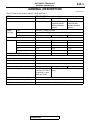

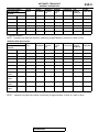

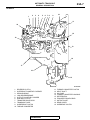
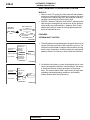
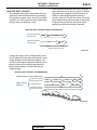
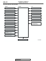
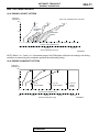
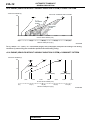
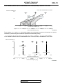
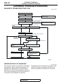

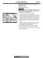

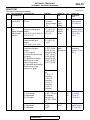
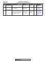
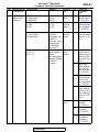
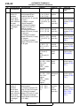
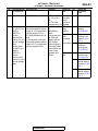
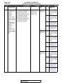

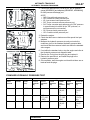
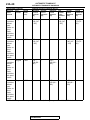
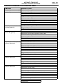
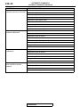
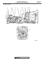
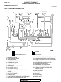


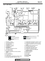
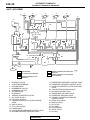
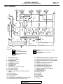
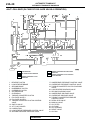
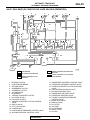
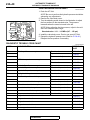
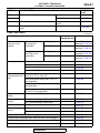
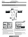

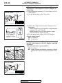


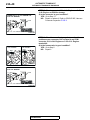
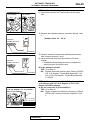

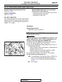

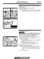
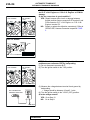
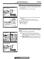
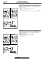
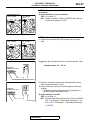
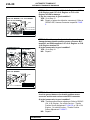
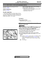
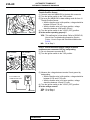
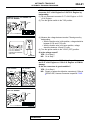
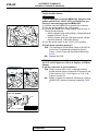

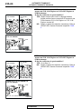
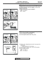

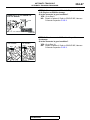

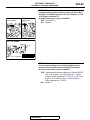
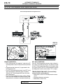
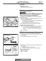

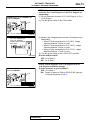
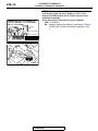
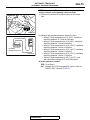

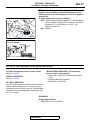
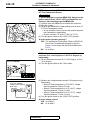
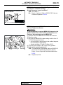


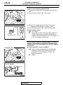
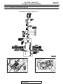
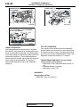
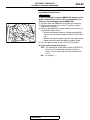

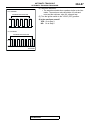
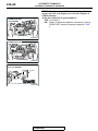
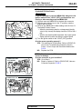

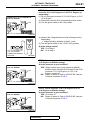
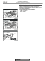
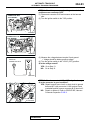
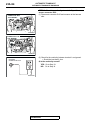
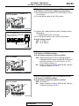

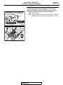
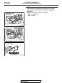
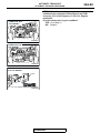

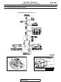
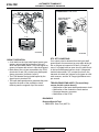

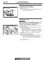
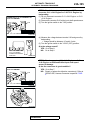
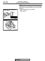
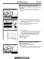
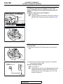
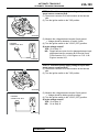

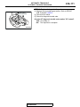


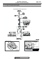


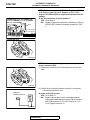
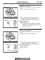
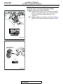
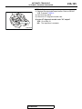

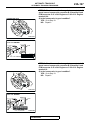
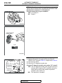


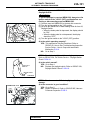
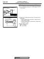
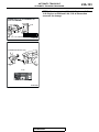
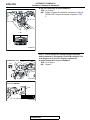
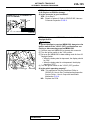
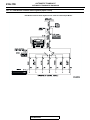
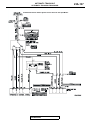
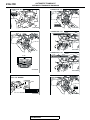
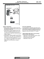
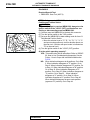

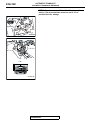
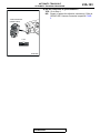
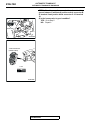
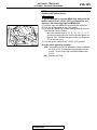
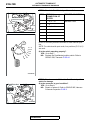
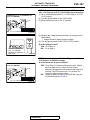
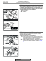
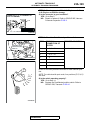


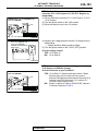

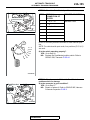

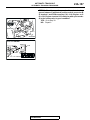

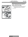

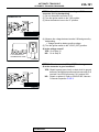

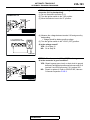
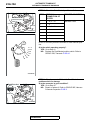
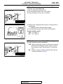
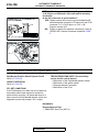


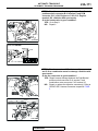

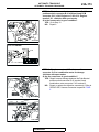

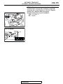
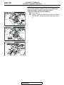
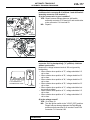
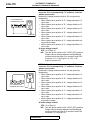
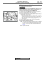

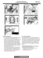

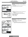

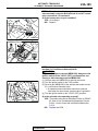
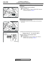


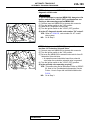
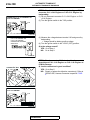
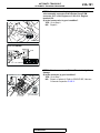

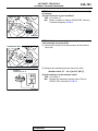
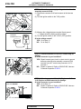
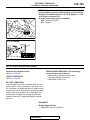

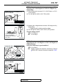


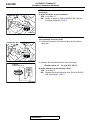
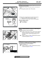


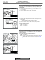

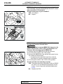
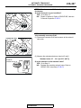


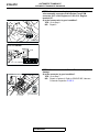
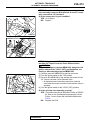
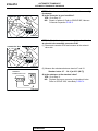
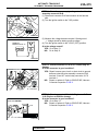
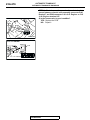
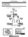
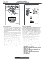
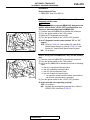
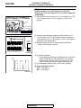

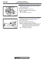
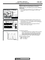
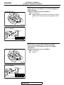


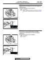
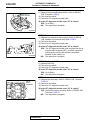
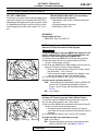
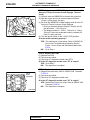
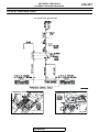
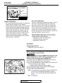
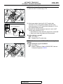
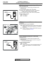


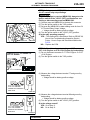

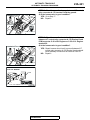
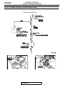
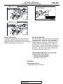
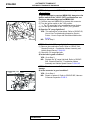
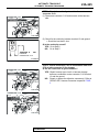
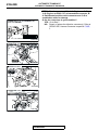
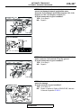
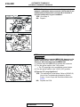

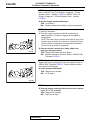
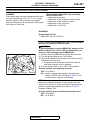
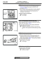
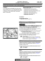


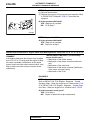
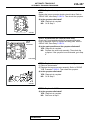
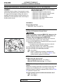
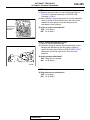

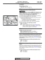
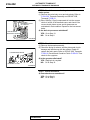
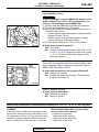


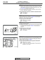
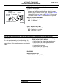
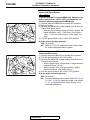
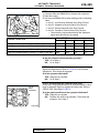
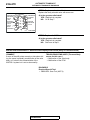

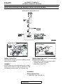
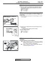
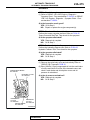
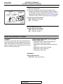
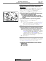
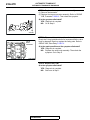

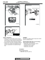
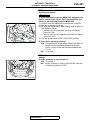
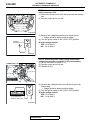
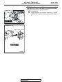
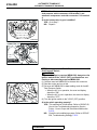
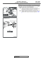
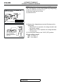
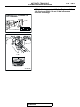
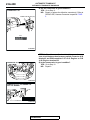
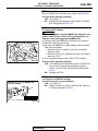
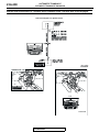
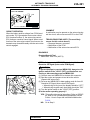
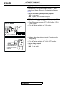
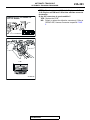
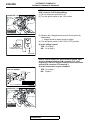
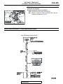

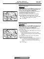
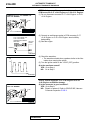

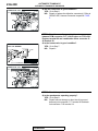
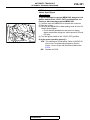
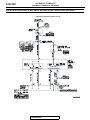
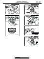
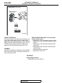
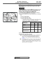
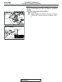
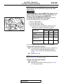
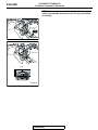


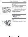
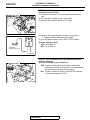
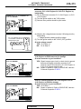

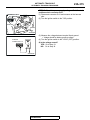


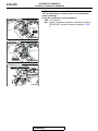

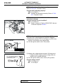


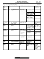
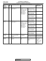
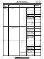

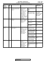
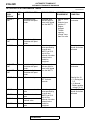
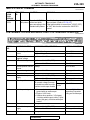
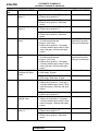
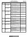
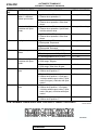

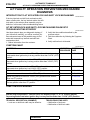


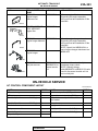

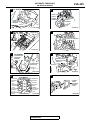
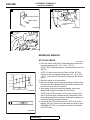

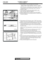


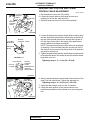
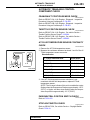
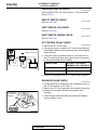

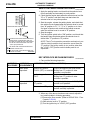

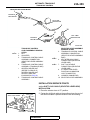
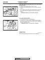
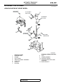
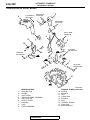
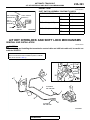
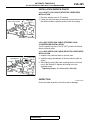

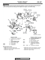

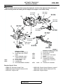
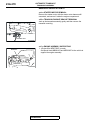

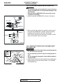
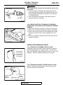

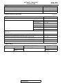


![VERUS PRO User Manual [3980kb PDF File] - Snap](http://vs1.manualzilla.com/store/data/005690474_1-9ff68923f14d7698ce72469cabae3990-150x150.png)