1
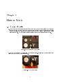
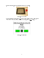
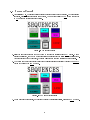
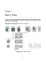
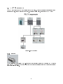
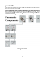
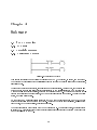
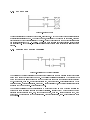
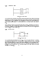
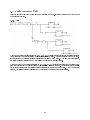
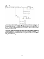
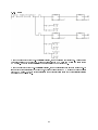
User Manual for Gantry Model Alan, Oliver, Kelly, Jeremy, etc. August 20, 2009 Contents 1 Introduction 2 1.1 Introduction . . . . . . . . . . . . . . . . . . . . . . . . . . . . . . . . . . . . . . . . . . . . . . 2 1.2 KÀ background . . . . . . . . . . . . . . . . . . . . . . . . . . . . . . . . . . . . . . . . . . . . 2 1.3 Gantry Model . . . . . . . . . . . . . . . . . . . . . . . . . . . . . . . . . . . . . . . . . . . . . 3 2 How to Use it 4 2.1 Start-up Checklist . . . . . . . . . . . . . . . . . . . . . . . . . . . . . . . . . . . . . . . . . . 4 2.2 Sequence Control . . . . . . . . . . . . . . . . . . . . . . . . . . . . . . . . . . . . . . . . . . . 6 2.3 Manual Control . . . . . . . . . . . . . . . . . . . . . . . . . . . . . . . . . . . . . . . . . . . . 7 3 How It Works 3.1 3.2 8 PLC Components . . . . . . . . . . . . . . . . . . . . . . . . . . . . . . . . . . . . . . . . . . . 9 3.1.1 9 motor Pneumatics 3.2.1 . . . . . . . . . . . . . . . . . . . . . . . . . . . . . . . . . . . . . . . . . . . . . . . . . . . . . . . . . . . . . . . . . . . . . . . . . . . . . . . . . . . . . . . . . . . Variable Pressure Regulator . . . . . . . . . . . . . . . . . . . . . . . . . . . . . . . . 3.2.2 4-Way 3-Position Solenoid Valve . . . . . . . . . . . . . . . . . . . . . . . . . . . . . . 11 3.2.3 Lift/Tilt Air Cylinders . . . . . . . . . . . . . . . . . . . . . . . . . . . . . . . . . . . . 11 4 Software 4.1 4.2 4.3 10 11 12 STEP 7 overview . . . . . . . . . . . . . . . . . . . . . . . . . . . . . . . . . . . . . . . . . . . 12 4.1.1 12 LAD logic . . . . . . . . . . . . . . . . . . . . . . . . . . . . . . . . . . . . . . . . . . . . . . . . . . . . . . . . . . . . . . . . . . . . . . . . . . . . . . . . . . . . . 12 4.2.1 Tutorial Programs Contacts and Outputs . . . . . . . . . . . . . . . . . . . . . . . . . . . . . . . . . . . . 12 4.2.2 Set and Reset . . . . . . . . . . . . . . . . . . . . . . . . . . . . . . . . . . . . . . . . . 13 4.2.3 Positive and Negative Transition 4.2.4 Comparing Values 4.2.5 Moving Words Basic Movement Code . . . . . . . . . . . . . . . . . . . . . . . . . . . . . . 13 . . . . . . . . . . . . . . . . . . . . . . . . . . . . . . . . . . . . . . 14 . . . . . . . . . . . . . . . . . . . . . . . . . . . . . . . . . . . . . . . . 14 . . . . . . . . . . . . . . . . . . . . . . . . . . . . . . . . . . . . . . . . 15 4.3.1 Lift . . . . . . . . . . . . . . . . . . . . . . . . . . . . . . . . . . . . . . . . . . . . . . 15 4.3.2 Tilt . . . . . . . . . . . . . . . . . . . . . . . . . . . . . . . . . . . . . . . . . . . . . . 16 4.3.3 Spin . . . . . . . . . . . . . . . . . . . . . . . . . . . . . . . . . . . . . . . . . . . . . . 17 5 Troubleshooting 18 1 Chapter 1 Introduction 1.1 Introduction Cirque du Soleil, French for "Circus of the Sun", was founded in 1984 by Guy Laliberté. What started out with 73 employees in Montreal, Quebec, now has more than 3,800 employees in over 40 countries. The company's annual revenue exceeds $600 million, which come from its tent performances and permanent show locations. Las Vegas is home to several permanent Cirque du Soleil productions, and that includes Love at the Mirage, and Zumanity, at New York, New York. Other productions are "O" at the Bellagio, and Mystere at Treasure Island. Love is a tribute show to the Beatles music, while "O", (a play on the French word for water, eau), is a show that is completely immersed in water. 1.2 KÀ background KÀ is one of Cirque du Soleil's most recent and technologically advanced permanent productions at the MGM Grand in Las Vegas, Nevada. The primary feature of the production is the main stage platform, also known as the Sand Cli Deck. It is attached to a Gantry Lift System that allows the deck to have multiple degrees of freedom. The gantry lift system can lift the stage vertically up to 70 feet at 2 feet per second. It can also tilt the deck forward to 110 degrees. It also has the ability to rotate the deck continuously at 2 rotations per minute. Hydraulics are utilized to lift and tilt the deck, and electric motors help rotate the deck. Mining and manufacturing equipment and parts were some of the main components used to make the stage of KÀ. The Sand Cli Deck measures 25' by 50' by 6' and weighs approximately 80,000 pounds. It is mounted on a knuckle-like mechanism that allows the deck to rotate up to two revolutions per minute. The Sand Cli Deck and knuckle-mechanism are connected to a cantilevered torsion tube. There is an outrigger arm that extends outward toward the audience. On the underside of the sand cli deck, there is a pivot joint that is referred to as the wrist or knuckle. This joint is attached to one end of the outrigger arm. A 10 foot diameter Rotek bearing is located where the joint and the outrigger arm meet. These types of Rotek bearings are usually used in tower cranes. Four gigantic 70 foot stroke hydraulic cylinders guide the movement of the entire stage: sand cli deck, the knuckle, the outrigger arm, the torsion tube, and hammerheads. The torsion tube is mounted on the gantry lift, and is responsible for the vertical motion of the deck. This torsion tube, or torque tube, is a massive 6 foot diameter cross tube. The ends of the tube are connected to two hammerheads on both sides of the tube. These hammerheads run along a track that is connected to the support columns. The hammerheads are responsible for the vertical motion of the lift; the tube does not rotate in any way. The two hammerheads are guided by 75-ton and 150-ton capacity Hilman rollers that that travel on steel plates on the columns. The rollers, manufactured by the Hilman Company of Marlboro, New Jersey, are used to move much heavier loads, such as oil rig components, bridges, and entire buildings. 2 The gantry lift has two sets of dual-piston, electromagnetically actuated brakes. One set is located on either side of the support column brakes. t the design of the lift. These brakes are usually used for mining, but were modied to They must also be inspected and replaced on a regular basis to keep a smooth operation of the lift. The support columns located on stage left and right are 4 foot diameter steel tubes, and are approximately 70 feet in length. The bottoms of the columns are connected to the oor and to the roof of the building. They are also mounted to the enormous frame that goes along the perimeter of the lift system. Because of the structure and mounting of the columns, it created a 75 foot tall building within the MGM Grand. The tubes were tted with acoustical dampers that keep them from acting like pipe organs. 1.3 Gantry Model An approximate 1:20 scale model of the KÀ lift system was constructed. The model has almost all the moving capabilities of the larger lift. 3-D modeling software was used for conversions of the actual dimensions of the real system. Due to the small size of the lift, it needed some redesigning of some parts. Some parts had to be simplied, while other parts were eliminated completely from the design. Every attempt was made to keep the small design similar to the original, but components such as the hammerheads and knuckle needed to be redesigned for practical set up and assembly. Other components that were eliminated were the brake system. This lessened the complexity of the scale model. The drive system for the main lift and its tilt functions were switched from hydraulics to pneumatics. Two pneumatic cylinders are anchored at the rear of the torsion tube and the front of the connector that joins the stage to the knuckle. These pneumatic cylinders are responsible for the tilting motion of the stage. 3 Chapter 2 How to Use it 2.1 Start-up Checklist 1. Check the output psi (the larger dial next to the husky knob) on the air compressor to make sure the tank is at 95 psi. The husky knob is the control to adjust this number.If the master psi (the smaller dial above the larger one) is less than 95 psi, you will need to turn on the compressor until the master psi is at least 95 psi. The compressor will automatically turn o if the pressure reaches 120 psi. Figure 2.1: The Master and Output Dials 2. Hook up the nozzle from the lter system to the air compressor. It slides into the brass tting below the husky knob but may take a little eort. Figure 2.2: The Output Nozzle 4 3. Rotate the large red E-Stop button clockwise to turn on the LCD screen. Figure 2.3: The LCD Screen 4. After the title screen appears, press the USE button to begin operating the gantry model. Or, If you wish to learn more about the gantry model and how it works, press the TOUR button. Figure 2.4: The Title Screen 5 2.2 Sequence Control 1. After selecting USE, the sequence screen will take approximately 15 seconds to load. To begin running sequences, once the Sequence screen has appeared, you must rst press the OFF button to switch it to ON in order to activate sequence control. Figure 2.5: The Sequence Screen 2. Select the numbered sequence you want to run by tapping the corresponding SEQ# button. Once a Sequence is selected, the Gantry model will perform all sequences that follow it in numerical order. After completion of the 5th sequence, the stage will return to its home position and stop running. 3. The Gantry can be set to repeatedly cycle through all 5 sequences numerically by tapping the REPEAT button to the left of the SEQ 1 button. Figure 2.6: The Manual Control Screen 4. To end a sequence prematurely, or to return the gantry to its initial position, press the HOME button. 6 2.3 Manual Control 1. After selecting USE, the sequence screen will take approximately 15 seconds to load. To begin manually controling the gantry, press the to Manual button. Once the manual control screen has appeared, press the OFF button to switch it to ON in order to activate manual control. Figure 2.7: The Manual Control Screen 2. Press the corresponding button to perform the desired action The UP buttons will lift the stage upwards. The DOWN buttons will lower the stage The TILT buttons will tilt the stage towards its vertical position The FLAT buttons will tilt the stage towards its horizontal position The Right SPIN button will rotate the stage Clockwise The Left SPIN button will rotate the stage CounterClockwise 3. NOTE: Movement will only occur while a button is being pressed. Once it is no longer held down, the stage will stop moving. 4. To return the stage to its initial position, press the HOME button. Figure 2.8: The Manual Control Screen 5. If any of the stage's movement become erratic or out of control press the ESTOP button to immediately cease all movements 7 Chapter 3 How It Works The stage can be separated into two separate systems: the control system, and the pneumatic system. The systems work together to control stage movement. (See Figure x). This section will explain the physical aspect of how movement is achieved. Figure 3.1: Wiring and Pneumatic Diagram 8 3.1 PLC Components The PLC components make up the control system of the stage. These components are responsible for the regulating the lift, tilt and rotation of the stage. (For lift and tilt motion, see section PNEUMATICS) Figure 3.2: PLC Diagram 3.1.1 motor The motor's speed is controlled by an H-bridge chip which receives a pulse width modulated (PWM) signal from the PLC. Atttached to the output shaft of the motor is a small spur gear which meshes with a larger gear attached to the stage. 9 3.2 Pneumatics Pneumatics is the use of pressurize gas to create motion. In this application, an air compressor provides the air used to power the pneumatic components. The PLC controls the pneumatic system by regulating air pressure and ow. By varying these two factors as outputs to the air cylinders, dynamic movement of the stage is achieved. There is a total of four output air lines (two per solenoid valve). Each air cylinder has two inputs for a total of eight in the system. Because of this, each output air line from the solenoid uses a T-splitter to double the output lines, which allows one valve to control a cylinder pair. Figure 3.3: Pneumatic Diagram 10 3.2.1 Variable Pressure Regulator Varies the air pressure of incoming air to control the speed of the pneumatic air cylinders. 3.2.2 4-Way 3-Position Solenoid Valve Controls the passage of air to the lift and tilt air cylinders. A solenoid is a coil of wire through which an electric current passes through, creating an electromagnet that triggers a mechanical switch. This controls the ow of uid as the electric current changes the state of the valve. It is normally closed; and applied electric current allows air to ow through. (see SOLENOID VALVE) 3.2.3 Lift/Tilt Air Cylinders Dual action cylinders that provide lift and tilt motion.The air cylinders are composed of an outer cylinder and a piston rod. In this application, dual action air cylinders are used. This means that air can be input at either end of the cylinder to push the piston rod in either direction. The linear motion of the rod creates the lift and tilt movement of the stage. 11 Chapter 4 Software 4.1 4.1.1 4.2 4.2.1 STEP 7 overview LAD logic Tutorial Programs Contacts and Outputs Figure 4.1: Contacts and Outputs This sample showcases the most basic symbols found in STEP 7, the contact, or switch, and the output. The contact symbol consists of two parallel lines while the output symbol is the closed set of parentheses, also called a coil. There are two basic types of contacts, normally open and normally closed. As seen above, in the second line of the example, the normally closed contact is represented by two parallel lines with a / between them. When a normally open contact is closed, or turned ON it's read as TRUE. A contact can be turned ON through the activation of an input sensor, or by an output elsewhere in the program. This is your basic switch, much like a light switch. On the other hand, a normally closed contact is TRUE when the contact is open, or OFF. The best example of this would be an emergency stop button. As long as the button is not depressed, everything can keep working, but when it is pressed, functions must cease. The output is activated when there is a TRUE path leading to it. When this is the case, a certain contact is turned ON. This contact could be just another variable used elsewhere in the program or it could turn on a device attached to the PLC. 12 4.2.2 Set and Reset Figure 4.2: Set and Reset These are variations on the standard output coil, Reset and Set. They can be used to turn multiple contacts at sequential addresses on or o. The Reset command, represented by a coil with an R inside, turns the contact located at the address represented by Reset_Adrs ONas well as the the number of locations after the address, represented by #_of_Points. The Set command operates in the same fashion, except it turns the contacts ON. In both cases, the contacts will remain in their new state until changed elsewhere in the program. 4.2.3 Positive and Negative Transition Figure 4.3: Positive and Negative Transition The Positive and Negative Transition commands are very useful when you need a certain action to occur just once when a switch has been turned on or o. The Positive Transition is represented by a contact symbol with a P between the lines and is set to TRUE for only one scan when the preceding contact is turned ON. For example, when NO_Switch is rst turned ON, the output Pos_Edge is also turned ON but only for one scan. After the initial scan, even if NO_Switch is still ON,the Positive Transition contact is no longer TRUE and so Pos_Edge is turned OFF. The Negative Transition command is represented by a contact symbol with an N between the lines and works in the exact opposite manner as the Positive Transition. It is set to TRUE for one scan when the preceding contact is turned OFF. So, in the example above, when NO_Switch is turned OFF, the output Neg_Edge is turned ON for a single scan. After that single scan, Neg_Edge is returned to its OFF state. 13 4.2.4 Comparing Values Figure 4.4: Comparing Values The Compare command does exactly what it says: compares the value stored at one address to another value. One use of the Compare command is to activate other commands based on the value of a timer. There are several dierent types of comparisons that can be done, such as Greater Than (>), Less Than (<), and Equal To (==). The Compare commands are represented by a contact symbol with the appropriate mathematical representation followed by the letter identier for the type of value being compared inside the lines. In the top line in the example above, if the integer value stored at Value_Adrs is less than or equal to the value of Compared_Val, the output Less_Than will be turned ON. In the bottom line of the example, is the integer value stored at Value_Adrs is greater than or equal to the value of Compared_Val, the output Greater_Than will be turned ON. 4.2.5 Moving Words Figure 4.5: Moving Words The Move function is another straightforward command. When the EN input receives a TRUE signal, the function writes a certain value from the IN terminal to a location designated at the OUT terminal . If the operation is successful, the ENO output sends a TRUE signal on to the rest of the line. If for some reason the operation cannot be completed, an error message is registered, and ENOoutputs a FALSE signal. There are dierent versions of the command used to move certain types of values, such as words or integers. In the above example, the MOV_W function is writing the word value Word to the address represented by Destination. 14 4.3 Basic Movement Code All of the sample codes below operate under the condition that the E-Stop is not activated and that Manual Control is not disabled. 4.3.1 Lift When one of the lift buttons is pressed (M1.2, M1.3, M1.4), a pressure value greater than the resting pressure (8000 psi)is sent to the lift regulator (REG2) which raises the stage.A greater dierence between the regulator pressure and the resting pressure will result in the stage moving faster. When the button is released, the resting pressure value is sent to the regulator to maintain the stage's position. When one of the Lower buttons is pressed (M1.5, M1.6, M1.7), a pressure value less than the resting pressure (8000 psi) is sent to the lift regulator (REG2) allowing the stage to lower. A greater dierence between the regulator pressure and the resting pressure will result in the stage moving faster. When the button is released, the resting pressure value is sent to the regulator to maintain the stage's position. 15 4.3.2 Tilt When one of the tilt buttons is pressed (M2.0, M2.1, M2.2) the tilt control signal is set to High, which will cause the appropriate side of the tilt solenoid (SP1) to open. A pressure value is sent to the regulator (REG1) to control the speed of the action (more pressure = more speed), for as long as the button is pressed. When the button is released, the tilt control signal is reset to Low, causing the solenoid to return to its closed position, stopping the movement. When one of the Flatten buttons is pressed (M2.3, M2.4, M2.5) the atten control signal is set to High, which will cause the tilt solenoid (SP2) to open the side opposite that used for tilting. A pressure value is sent to the regulator (REG2) to control the speed of the action (more pressure = more speed). When the button is released, the atten control signal is reset to Low, causing the solenoid to return to its closed position, stopping the movement. 16 4.3.3 Spin When the Spin Right button (M1.0) is initially pressed, the motor is set High (turned on). As long as the button is continued to be held down, a value of 4 is set for the PWM cycle and a value of 3 is set for the PWM pulse. When the button is released the motor is reset to Low (turned o ). When the Spin Left button (M1.1) is initially pressed, the motor is reversed and set High (turned on). As long as the button is continued to be held down, a value of 4 is set for the PWM cycle and a value of 3 is set for the PWM pulse. When the button is released the motor is reversed again back to its original direction and reset to Low (turned o ). 17 Chapter 5 Troubleshooting The PLC doesn't work For further assistance, consult the PLC's operation manual Make sure the PLC is turned on, in run mode, the stop switch is o, and the start switch is on Make sure the air tank is open with the regulator set to 100 PSI Make sure the pneumatics lines are all hooked up Make sure the electronic regulator is functioning properly Make sure there is nothing obstructing the movement of the air ram Make sure the output and input LEDs on the PLC are turning on Make sure the PLC is turned on, in run mode, the stop switch is o, and the start switch is on Make sure the air tank is open with the regulator set to 100 PSI Make sure all of the pneumatics lines are hooked up Make sure the electronic regulator is functioning properly Make sure there is nothing obstructing the movement of the stage Make sure the output and input LEDs on the PLC are turning on The stage won't rotate when Pulse Width Modulation is applied Try troubleshooting the program The stage won't tilt when the button is pressed Make sure it's in run mode The model doesn't move when the lift button is pressed Make sure it's plugged in Make sure the PLC is turned on, in run mode, the stop switch is o, and the start switch is on Make sure the motor is wired properly to the H-Bridge circuit and power Make sure there are no shorts on the H-Bridge circuit Make sure there is nothing obstructing the movement of the stage Make sure the output and input LEDs on the PLC are turning on The stage doesn't change direction when the direction switch is applied Make sure the H-Bridge circuit is properly attached to the PLC Make sure there are no shorts on the H-Bridge circuit Make sure the output and input LEDs on the PLC are turning on 18

![ECT[DIN] [DIN] - Moore Industries International](http://vs1.manualzilla.com/store/data/005778735_1-93255c4f7d497ff32afcfe496e72d982-150x150.png)