1
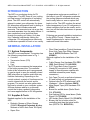
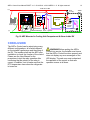
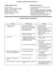
ARPrv Control v1.0
General Install Guide
doc-v1.0
Terms -- Conditions & Contact Information
This manual is copyrighted © by ARPC L.L.C. 2013-2014. All rights are reserved. This manual may only be reproduced
with permission of ARPC L.L.C.. This manual is furnished for informational use only and is subject to change without
notice. This manual does not imply any commitment on the part of ARPC LLC or its business partners. ARPC L.L.C. and
its business partners assume no responsibility or liability for any error or inaccuracies that may appear in this manual.
By use of this document for installation and operation of the ARP Control, the user is agreeing to the ARPC L.L.C. terms
and conditions found in document ARPC LLC License Agreement.pdf. Also, the end user needs to understand Section
1.6 of the User Manual; the end user has been informed that the ARP Control can be turned off at any time, thereby
removing the ARP Control function and reverting to the operation of the refrigerator to its previous state. Power surges
can turn off the ARP Control just the same as any equipment in an RV.
The document "ARPC LLC License Agreement.pdf" can be downloaded at web address
http://www.ARPrv.com
or, please send any request to e-mail address below, ARPC L.L.C. will supply information in a timely manner:
[email protected]
CONTENTS
SAFETY .................................................................................................................................... 1
1.1 Acronyms and Abbreviations ....................................................................................... 1
1.2 Hazard Information ...................................................................................................... 1
1.3 Work Safely ................................................................................................................. 1
1.4 Terms & Warnings Symbols ........................................................................................ 1
1.5 Operation Safety.......................................................................................................... 1
1.6 ARP Control and your Refrigerator.............................................................................. 1
INTRODUCTION ....................................................................................................................... 2
GENERAL INSTALLATION...................................................................................................... 2
3.1 System Components ................................................................................................... 2
3.2 Supplies & Tools.......................................................................................................... 2
INSTALLATION - RTD.............................................................................................................. 3
4.1 Mounting the Temperature Sensor .............................................................................. 3
INSTALLATION - CONTROLLER ............................................................................................ 6
5.1 Location....................................................................................................................... 6
5.2 Interior Location........................................................................................................... 6
5.3 Mount Housing Inside.................................................................................................. 7
5.4 Exterior Mounting ........................................................................................................ 7
5.5 Mount Housing Exterior ............................................................................................... 7
WIRING the ARP ...................................................................................................................... 7
6.1 General Information..................................................................................................... 7
6.2 Good Wiring Practices................................................................................................. 8
6.3 Wiring the Ground ....................................................................................................... 8
6.4 Wiring the Power ......................................................................................................... 8
6.5 Wiring the Relay .......................................................................................................... 9
6.6 Temperature Sensor Wiring ...................................................................................... 10
6.7 Wiring Options ........................................................................................................... 10
CONCLUSION ........................................................................................................................ 12
© 2014 ARPC L.L.C. All rights reserved.
ARPrv Control User Manual DRAFT v1.0 02/14/2014 © 2014 ARPC L.L.C. All rights reserved.
1
SAFETY
1.1 Acronyms and Abbreviations
ARP: ARP Control = ARPrv Control
GND: Ground
NC: Normally Closed Relay Contact
NO: Normally Opened Relay Contact
P/N: Part Number
RTD: ARP Control temperature sensor;
Resistance temperature detector is the type
of sensor used.
1.2 Hazard Information
Hazard information includes terms, symbols
and instructions used in this manual or on
the equipment to alert operating and service
personnel to the recommended precautions
in the care, use and handling of the ARP.
1.3 Work Safely
There are many ways to install the ARP.
Make safety your first priority! The
installer’s knowledge, skill, and ability are
important for safely installing the system. If
you are unsure of your ability to do the
installation, have a qualified installer do the
work.
1.4 Terms & Warnings Symbols
1.5 Operation Safety
The ARP Control and 'ARPrvSafe' infer that
the use and operation of this control can add
a level of safety to your absorption
refrigeration system in your RV. No other RV
absorption refrigerator control monitors the
boiler temperature, and turns off the heat
source to the refrigerator before damage can
be done to the internal fluids in the
refrigerator cooling unit. The ARP cannot
prevent RV refrigerator failure if the
manufacture built the cooling unit in a
manner that would result in premature failure.
1.6 ARP Control and your
Refrigerator
The ARP Control is designed to work in
conjunction with the manufactures safety
devices that are presently on your RV
refrigerator. Many of the manufactures over
temperature devices have proven to turn off
the refrigerator unnecessarily, rendering the
refrigerator useless. Due to this common
complaint, the ARP control can be turned off
using the On/Off button. The end user does
not need to fear a potential situation where
the ARP Control keeps the refrigerator from
performing its normal function. Thus, when
the ARP Control is off, your refrigerator is still
protected by the manufactures safety
devices. It is the end user's responsibility to
insure that the ARP Control is installed and
functioning properly at all times, this includes
the state of the control being turned on or off.
DANGER Never remove or bypass any
manufacture safety device when installing
the ARP Control. Be aware that the ARP
Control can be turned off thereby preventing
its function. Know and understand you RV
electrical system and its integrity for proper
ARP Control use. RV electrical systems
integrity are complex due to the inclusion of
charging systems such as solar systems,
generator, inverters and 120VAC chargers
just to mention a few sources of electrical
disruption that can result in disruption of ARP
Control function. Always consult a certified
RV repair facility and/or the manufacture of
your RV if you are concerned about safety
issues.
ARPrv Control User Manual DRAFT v1.0 02/14/2014 © 2014 ARPC L.L.C. All rights reserved.
2
INTRODUCTION
The ARP is a monitoring device for RV
refrigerators. The ARP turns off your cooling
unit heat source if refrigeration is not taking
place. The ARP control will automatically
attempt to restart your refrigerator five times.
RV absorption refrigerators work by boiling a
fluid mixture that includes water and
ammonia. The ammonia turns into a gas that
rises and separates from the water mixture. It
then condenses into a liquid that flows
through the cooling unit tubing. As it does
this, it absorbs heat thereby cooling the
refrigerator. RV refrigerators are notoriously
unsafe when operated off-level or in a variety
of temperature and pressure conditions. If
the boiler in your RV refrigerator overheats,
the cooling tubes are stressed which may
lead to early failure or even a rupture that
leads to a fire. The ARP monitors the actual
boiler temperature of your RV refrigerator to
detect conditions that can be unsafe, and in
turn, turn off the boiler heat source to prevent
overheating.
Following are general installation instructions
for the ARPrv Control. Please check the
Install Supplements for various refrigerators
make and model information.
GENERAL INSTALLATION
3.1 System Components
The ARP is not complicated. The system has
the following components seen in Fig. 1.
• Controller
• Temperature Sensor (RTD)
• Relay
• Fuse
The RTD sensor measures the temperature
of the boiler process tube. The controller
looks at this information and is programmed
to send a signal to open the normally closed
(NC) relay when a condition exists that may
indicate overheating. Depending on the
control ordered, a variety of functions can be
used to interact with the control and its
program. The control can also gather data
that can be stored on your computer system.
All these features add up to a universal
control that is also a powerful diagnostics
tool never applied before to RV refrigeration.
3.2 Supplies & Tools
Needed supplies for the installation of the
ARP:
•
•
Dielectric Grease or Silicon Grease
(CAMCO Electrical Protectant & Lube;
Walmart or NAPA Auto Parts 'Sil-Glyde')
Super Glue
•
Fiber Glass Insulation (Typical Hardware
Store High Temp Pipe Wrap; Granger
Item #: 4LFD2; McMaster-Carr P/N:
9356K11)
Optional supplies for the installation of the
ARP:
• Cable Clamps (Ace Hardware P/N: PPC1525; Radio Shack P/N: 640-3039)
• 0.25" Piggy-Back Crimp Connector
(Handy for connection of ARP power
supply to Norcold power supplies with
standard automotive power supply
connectors)
• Fish Tape (To push or pull wires between
RV and cooling unit compartment)
• Optional clips for RTD attachment (ACE
Hardware -- Hilman Hardware 58410)
• Metal Repair Tape (ACE Hardware P/N:
47523)
• Buzzer for audible alarm (Radio Shack
P/N: 273-0059)
• Red flashing LED for visual alarm (Radio
Shack P/N: 276-0036)
• LED holder (Radio Shack P/N: 276-0079)
• Blower, this fan is better suited for
controlling heat than the typical muffin
fans (DELTA P/N: BFB1012L)
ARPrv Control User Manual DRAFT v1.0 02/14/2014 © 2014 ARPC L.L.C. All rights reserved.
•
Heat conductive thermal mastic for
evaporator when/if installing new cooling
unit: (Devan 310 Sealants, Inc)
•
3
ARP housing black mounting screws (Ace
-- Hillman Hardware 8x12 P/N: 4440-J)
INSTALLATION - RTD
4.1 Mounting the Temperature
Sensor
Fig. 2 is a drawing of a typical RV which
includes the living space and the refrigerator
installation. The exterior shell of the RV,
including the cooling unit access door is
removed for ease of viewing. This figure
gives the installer a general idea of what will
be found inside the cooling unit compartment.
The temperature sensor clips onto the boiler
process tube. Fig. 5 shows a cutaway view of
the boiler assembly and the RTD with clip.
1. Open the access door to expose the rear
of the refrigerator.
2a. For refrigerators that have metal boiler
housings, open the heater access door as
seen in Fig. 4. To open the door, there is a
tab that goes into the slot seen in Fig.4,
straighten the tab and open the door. Once
the door clears the heaters, push the door up
to unlock the lower hinge. Now the door can
be removed.
2b. For refrigerators that have foil boiler
housing, such as the Norcold 1200, pull out
the section of insulation inserted with the
Norcold recall. Please reference the
document found at our web site on page
Installation Procedures, file:
Norcold recall documentation & Installation
Guidelines
Fig. 1 ARP Control Kit
ARPrv Control User Manual DRAFT v1.0 02/14/2014 © 2014 ARPC L.L.C. All rights reserved.
4
Fig. 2 Cutaway of Typical Cooling Unit Installed in RV
Fig. 3 Typical Inside View of Refrigerator Installation
3. Push the insulation aside to allow you to
identify the various tubes. The insulation may
also be removed by removing sections to
gain access to the tubing inside.
4. You will mount the sensor to the boiler
process tube. This tube is most easily
identified by the fact that the electrical heater
mount tubes are welded directly to the boiler
ARPrv Control User Manual DRAFT v1.0 02/14/2014 © 2014 ARPC L.L.C. All rights reserved.
process tube. Most Norcold refrigerators
have a flue tube on the back of the boiler
tube as viewed looking into the boiler
housing. Dometic cooling units generally
have the flue in front of the process tube.
The location of the flue tube determines the
RTD housing and clip alignment in step 5. As
seen in Fig. 5, the RTD clip is aligned for a
Dometic installation because the clip is to the
left of the RTD as seen in this view. The
Norcold clip is opposite; the clip would be to
the right as seen in Fig. 6.
5
6. Determine the position of the RTD so that
it meets the following criteria:
•
•
•
•
The sensor is touching the boiler process
tube.
The sensor is away from all heat sources
including the flue tube.
The sensor is a least 1” above the electric
heating elements, preferably 2" to 5".
The maximum height is below the upper
absorber coil seen in Fig. 5.
CAUTION Do not mount the RTD on
the red flue tube as seen in Fig. 5, this will
damage the RTD by overheating. Please see
Auto Tuning section for further information.
5. Referencing Fig. 5, the RTD and clip are
shown, where the RTD has been supper
glued to the clip for ease of installation. Note
that the wires exiting the RTD housing are
aligned away from the center of the clip so
that insulation can be placed between the
boiler process tube and the RTD wires.
Note: If the clip is glued in the wrong position,
use Acetone to release the supper glue. Do
not get Acetone on the wire end of the RTD.
Fig 5 Install Temperature Sensor
Fig. 4 Boiler Housing with Open Heater
Access Door and RTD Clipped on
Fig. 5 shows a typical Dometic installation of
the ARP RTD. The red tube seen in this
figure is the gas flue tube, make sure the
RTD is not in contact with this tube, and the
ARPrv Control User Manual DRAFT v1.0 02/14/2014 © 2014 ARPC L.L.C. All rights reserved.
RTD is very well insulated from this heat
source.
6
RTD measurement and insure an accurate
measurement of the boiler process tube.
7. Once the position of the RTD has been
determined, either spray silicone lubricant, or
rub silicone grease on the clip and the boiler
tube to aid with step 8 below. Snap the RTD
around the boiler process tube very near the
location you determined.
8. Position the RTD to meet the criteria in
step 6 above by sliding the RTD from side to
side, or up and down.
9. Repack the insulation you may have
moved. Pack extra insulation around the
sensor and between the sensor and any heat
sources such as the flue tube and the electric
heaters. Referencing Fig. 6, pack insulation
around the clip and in the direction of the
green arrows. This will help prevent the flue
tube and electric heaters from affecting the
Fig. 6 Insulate RTD
INSTALLATION - CONTROLLER
5.1 Location
Decide whether you will install the ARP
controller inside the living space of the RV or
in the exterior access door for the cooling
unit. Either way works, if you like to view the
control data frequently, you may want it
inside. If you do not want to run wiring inside
the living compartment, then the exterior
installation may work best for you. The
general approach to installation is the same
regardless of where you decide to mount the
components. Referencing the figures, you
will need to locate the following features of
your RV refrigeration system:
•
•
•
Cooling unit access door (louvered door
that accesses the rear of the refrigerator)
Refrigerator manufacturers' control unit
Suitable power supply
5.2 Interior Location
Fig. 3 is a drawing of the inside view for a
typical RV refrigerator installation. Please
note the black ARP housings which
represent possible locations to mount the
ARP inside the RV. These are some
suggestions for mounting locations that have
spaces behind them for routing the wires.
Most Dometic refrigerators have a wiring
conduit from inside, behind the refrigerator
controls to the cooling unit area; this makes it
possible to mount directly on the refrigerator
control panel.
Once the best location for the controller is
decided upon, drill the wire routing hole in
the interior of the RV. Generally a 1/4" hole is
adequate. Next, if needed, push a wiring fish
tape through the hole to make sure that the
wires can be routed successfully to the
cooling unit compartment.
Tip 1: Often removal of the roof vent will
allow ease of wiring.
Tip 2: If it is desired to have an extra audible
alarm or flashing LED inside the RV, as seen
in Fig. 16, at this time consider routing extra
wires for these functions.
ARPrv Control User Manual DRAFT v1.0 02/14/2014 © 2014 ARPC L.L.C. All rights reserved.
5.3 Mount Housing Inside
7
Fig. 8 Typical Exterior Installation
Fig. 8 shows a typical installation where the
ARP is installed on the manufactures' control
box. Most of the manufactures controls have
1/4" of clearance between the components
inside the box and the outside housing where
the ARP is mounted. Please remove the
cover to the manufactures' control and check
the clearances if in doubt before drilling any
of the screw pilot holes.
Fig. 7 Mount Housing & Route Wires
5.5 Mount Housing Exterior
Fig 7 shows the ARP housing mounted. A
wire routing hole was drilled in the back of
the housing and aligned with the previous
section routing hole. Then, the screws are
inserted and the wires are then routed.
Fig. 9 shows three 1/4" holes drilled near to
the bottom edge of the control housing. This
allows any water to drain and the wires to be
routed as seen in Fig. 1 or 8 above.
5.4 Exterior Mounting
Fig. 9 Drill Drain/Wire Routing Holes
WIRING the ARP
6.1 General Information
Due to variations in refrigerator design to
which you may be adding the ARP, the
description of how to wire your particular
refrigerator may not be listed here. If you
have any difficulty, please contact our
technical support. Once installed, we
recommend you periodically test the ARP
relay to insure that the ARP and also the
manufactures' control are operating correctly.
All absorption RV refrigerators work on
similar principles. You can connect the ARP
control to turn off the heat source of your
absorption refrigerator using one of three
methods:
1. Stop power from reaching the
manufacture’s refrigerator controller.
2. Stop power from reaching the
manufactures’ flame sensor if the
refrigerator has a manual control.
3. Stop power from reaching the wire going
to or from the manufacturer’s temperature
monitoring device, such as the boiler
thermo-switch or NHTSA type recall kit.
Note: The ARP adds a higher level of
safety than most NHTSA kits because the
ARP measures boiler temperature and
turns off the heat source at a lower
temperature to avoid damaging the unit.
ARPrv Control User Manual DRAFT v1.0 02/14/2014 © 2014 ARPC L.L.C. All rights reserved.
CAUTION The ARP does not interfere
with the NHTSA or other kits provided by the
manufactures if and only if the ARP is
installed correctly. The ARP must be
connected so that the NC relay terminal is
connected in series with the manufactures’
safety device allowing the manufactures’
safety device to perform its normal operation.
Do not disable manufacturer safety
devices.
6.2 Good Wiring Practices
•
•
•
Always disconnect all power sources
before working on any electrical circuit.
Make the ground connection first. This is
important because most circuits use the
ground connection for safety and
overload prevention.
Make the ground connections at a single
point whenever possible. This helps to
avoid ground loops that interfere with
digital controls function. See Fig. 10.
8
are twisted in pairs with the black and red
wires from the ARP.
2. Identify the ground location of your
refrigerator. By viewing Fig. 11 & 12, the
typical power and ground terminals are
seen. Connect the 2 white ground wires
identified in Fig. 1 to the ground of your
system. You can use the ground screw
terminal, or another similar ground.
3. Verify that the boiler housing is grounded.
The boiler housing acts as a shield for the
ARP sensor. This housing should be
grounded or the ARP will pick up “noise”
from sources such as the gas SOV valve
and the gas igniter. This step is not
always necessary, but is recommended.
6.3 Wiring the Ground
ARP
Control
Manufactures'
Control
Boiler
Housing
Burner Housing
and SOV Valve
12VDC RV
Power Supply
Singular Grounding Point
Fig. 10 Single Grounding Point
The RV battery ground should always be the
final destination of any grounded circuit in
your RV. The battery ground is connected to
the chassis of the RV. You may need to
consider how the ground circuit in your RV
connects to the battery. Grounding requires
experience. If you are unfamiliar with ground
circuits, consult our technical support or a
professional installer. Use the following steps
to connect the ground for the ARP:
1. Identify the 2 white ground wires
extending from the ARP controller. They
Fig. 11 Typical Dometic Power Terminals
6.4 Wiring the Power
Often the best place to connect the power for
the ARP controller is the manufactures’
control 12VDC input. Use the following
method to connect the ARP to the power
source.
1. Locate the red wire extending from the
ARP housing, this wire will go to the fuse.
Note 1: The fuse is rated at 2-3 amps.
Note 2: The fuse will also supply power to
the relay in the next section.
ARPrv Control User Manual DRAFT v1.0 02/14/2014 © 2014 ARPC L.L.C. All rights reserved.
9
6.5 Wiring the Relay
Fig. 12 Typical Norcold Power Terminals
2. Connect the wire from the fuse to the
refrigerators 12VDC power supply. If you
cannot locate the power supply or your
system is different, contact technical
support. There are many ways you can
power the ARP.
An easy method to connect the relay is the
following:
Warning
ARP Control
Power Supply
Control Interrupt OUT
87
ARP Control
Relay Activation
87a
2 or 3 Amp Fuse
The ARP uses a typical automotive type
single pole double throw (SPDT) 30A relay.
You may use the relay connection to power
to a buzzer, LED, or other device to alert you
that the ARP has determine an overheating
condition, as well as to shut down power to
the refrigerator.
Note: A 30 amp relay works for most
applications. If higher amperage is needed, a
40 amp relay is readily available.
Fig. 13 shows the general ARP relay wiring.
In addition to wiring your own alarm, the
relay can be wired to turn off the heat source
to the refrigerator using one of three methods
as mentioned in section 6.1.
86(+)
30
85(-)
Power Supply
85(-)
86(+)
Control Interrupt IN
Relay Bottom View
87
Relay Isometric View
Fig. 13 ARP Relay Terminal Connections
Please note that the relay terminal numbers
are identified in Fig. 1 within parenthesis.
30 is wired to the +12VDC power supply that
will be interrupted by the NC relay switch, or
any supply that is desired to cut power to the
manufactures' control.
85 (–) is wired to the ARP black wire. The
ARP grounds the relay through this terminal.
86 (+) is wired through the fuse to +12VDC
power supply.
Always test all of the control functions after
installation.
87a is wired to the 12VDC power supply to
the manufactures' control which is interrupted
when the ARP senses a boiler overheat
situation.
87 can optionally be wired to any type of user
added alarm that will inform the operator of
an overheat situation, please see wiring
example Fig. 16 and 18 below.
CAUTION The installer must be carful
to not reverse the polarity on terminals 85
and 86. The reverse polarity will result in
failure of the switching device within the ARP.
When the ARP control activates the normally
closed (NC) relay terminal, it opens this
circuit, turning off the power to the
manufacturers' refrigerator controller. 30 is
connected to the power side of the NC switch.
ARPrv Control User Manual DRAFT v1.0 02/14/2014 © 2014 ARPC L.L.C. All rights reserved.
To connect it, locate the +12VDC connection
to the manufacturer’s refrigerator controller,
disconnect the wire from the +12VDC source
where it connects to the manufacturers'
refrigerator controller. Reconnect this wire to
relay terminal 30.
Note: You may need to protect this circuit
with an additional fuse of appropriate size
inline with the power supplied to the relay.
Ensure that all power connections are
properly fused. 87a is wired so as to supply
power through the NC relay connection to
the manufactures' refrigerator controller.
The ARP will attempt to restart your
refrigerator, in most cases before the internal
temperature of the refrigerator can rise.
When the ARP releases the relay, it returns
to its normally closed position and power is
restored to the refrigerator controller, so it
resumes its typical operation. 87a is
connected as the load side of the NC switch.
6.6 Temperature Sensor Wiring
Note: The white wire of this pair is not a
ground wire. The RTD wires are not
polarized; they may be installed in either
position on the sensor, please see Fig. 1.
6.7 Wiring Options
The following section uses engineering
wiring schematics, where the power and
ground are shown as rails on top and bottom
of the schematic. All of the components are
between the power rails. Please use the
manufactures' wiring diagram to confirm the
proper connections for a particular
installation.
Fig. 14 shows a general wiring scheme, on
the right of the schematic the relay is shown.
Please compare the following relay terminal
numbers to Fig. 13, where the numbers for
the terminals are shown in isometric,
schematic, and relay bottom views.
Fig. 15 to 18 is for reference, please contact
technical support with any questions.
The RTD temperature sensor is connected to
the ARP via a green/white twisted wire pair.
12VDC Power Rail
(+)
Warning
Fuse
Control Interrupt OUT
85
12VDC RV
Power Supply
86
87 87a
30
Control Interrupt IN
RTD
10
Twisted Pair Cable Identifier
(-)
Ground Rail
Fig. 14 General Wiring
ARPrv Control User Manual DRAFT v1.0 02/14/2014 © 2014 ARPC L.L.C. All rights reserved.
11
12VDC Power Rail
(+)
Fuse2 - Optional.
Rated for Manufactures's
Control
Fuse1
2-3 Amp
85
12VDC RV
Power Supply
86
87 87a
Manufactures'
Controller
30
Twisted Pair
Cable Identifier
RTD
(-)
Ground Rail
Fig. 15 Typical Universal Wiring
12VDC Power Rail
(+)
Fuse2 - Optional
Fuse1
2-3 Amp
85
12VDC RV
Power Supply
87 87a
86
RTD
(-)
Boiler
Housing
Thermal
Switch
Manufactures'
Controller
30
Twisted Pair
Cable Identifier
Flashing
LED
Fig. 16 Typical Dometic or Norcold Wiring
12VDC Power from RV
(+)
12VDC Power to Norcold Kit
Ground for Norcold Kit is a
clip, do not use for ARP
2A or 3A
Fuse
85
12VDC RV
Power Supply
86
RTD
(-)
87 87a
Manufactures'
Controller
30
Twisted Pair
Cable Identifier
Norcold High Temperature
(~800°F) Monitoring Kit
Ground Rail
Fig. 17 Norcold 1200 Series with High Temp. Monitoring Kit
ARPrv Control User Manual DRAFT v1.0 02/14/2014 © 2014 ARPC L.L.C. All rights reserved.
12
12VDC Power Rail
(+)
Fuse1
2-3 Amp
85
12VDC RV
Power Supply
86
RTD
(-)
87 87a
Audible
Alarm
Manufactures'
Controller
30
Twisted Pair
Cable Identifier Fuse2 - Optional
Ground Rail
DPDT
Control
Switch
Flashing
LED
Fig. 18 ARP Mounted in Cooling Unit Compartment & Alarm inside RV
CONCLUSION
The ARPrv Control can be wired using many
different configurations, all of which depend
on the installer’s preference and the wiring of
the RV. The installer shall test the ARP upon
installation to check the function of the control.
Please see the User Manual for the
procedures to test the relay operation after
confirming that the polarity of the relay is
correct. In addition, test to make sure that the
RTD temperature rises when the refrigerator
is turned on.
WARNING Before putting the ARPrv
Control into service, the installer must insure
that the ARPrv Control functions properly and
does not display any error messages on the
LED display. The end user must understand
the operation of the control so that safe
operation occurs at all times.