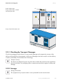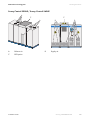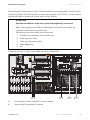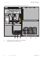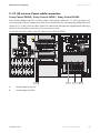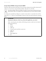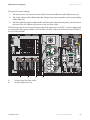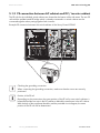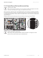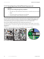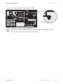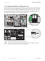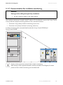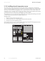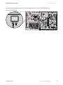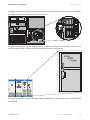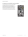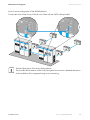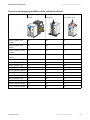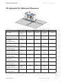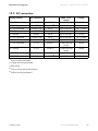
1
Central inverter
SUNNY CENTRAL 100LV - 560HE
Installation Guide
SC125_560HE-IEN083220 | 98-4004820 | Version 2.0
EN
SMA Solar Technology AG
Table of Contents
Table of Contents
1
1.1
1.2
1.3
1.4
Notes on this Manual. . . . . . . . . . . . . . . . . . . . . . . . . . . . . .
Validity . . . . . . . . . . . . . . . . . . . . . . . . . . . . . . . . . . . . . . . . . . . .
Target Group . . . . . . . . . . . . . . . . . . . . . . . . . . . . . . . . . . . . . . .
Storage of the Manuals . . . . . . . . . . . . . . . . . . . . . . . . . . . . . . .
Symbols Used . . . . . . . . . . . . . . . . . . . . . . . . . . . . . . . . . . . . . . .
7
7
7
7
8
2
2.1
2.2
Safety . . . . . . . . . . . . . . . . . . . . . . . . . . . . . . . . . . . . . . . . . . 9
Appropriate Usage . . . . . . . . . . . . . . . . . . . . . . . . . . . . . . . . . . . 9
Safety Instructions . . . . . . . . . . . . . . . . . . . . . . . . . . . . . . . . . . . 10
2.2.1
Personnel. . . . . . . . . . . . . . . . . . . . . . . . . . . . . . . . . . . . . . . . . . . . . . . . . . . . 10
2.2.2
Installation . . . . . . . . . . . . . . . . . . . . . . . . . . . . . . . . . . . . . . . . . . . . . . . . . . . 10
2.2.3
Special Hazards of Photovoltaic Systems . . . . . . . . . . . . . . . . . . . . . . . . . . . 11
2.2.4
Electrical Connection. . . . . . . . . . . . . . . . . . . . . . . . . . . . . . . . . . . . . . . . . . . 11
2.2.5
Power Supplies . . . . . . . . . . . . . . . . . . . . . . . . . . . . . . . . . . . . . . . . . . . . . . . 12
2.2.6
2.2.7
Disconnecting the device . . . . . . . . . . . . . . . . . . . . . . . . . . . . . . . . . . . . . . . 13
General Information . . . . . . . . . . . . . . . . . . . . . . . . . . . . . . . . . . . . . . . . . . . 15
3
3.1
Delivery. . . . . . . . . . . . . . . . . . . . . . . . . . . . . . . . . . . . . . . . 16
Transport. . . . . . . . . . . . . . . . . . . . . . . . . . . . . . . . . . . . . . . . . . 16
3.1.1
Transport Possibilities . . . . . . . . . . . . . . . . . . . . . . . . . . . . . . . . . . . . . . . . . . 16
3.2
Identifying the Sunny Central . . . . . . . . . . . . . . . . . . . . . . . . . . 17
3.2.1
Checking for Transport Damages . . . . . . . . . . . . . . . . . . . . . . . . . . . . . . . . . 19
3.2.2
Storage . . . . . . . . . . . . . . . . . . . . . . . . . . . . . . . . . . . . . . . . . . . . . . . . . . . . . 19
4
4.1
Mounting the Device . . . . . . . . . . . . . . . . . . . . . . . . . . . . . 20
Installation Site Requirements . . . . . . . . . . . . . . . . . . . . . . . . . . 20
4.1.1
Foundation . . . . . . . . . . . . . . . . . . . . . . . . . . . . . . . . . . . . . . . . . . . . . . . . . . 20
4.1.2
Distance to the wall. . . . . . . . . . . . . . . . . . . . . . . . . . . . . . . . . . . . . . . . . . . . 20
4.1.3
Inverter Protection Rating / EMC / Sound Levels . . . . . . . . . . . . . . . . . . . . . 20
4.1.4
Electrical Operating Room . . . . . . . . . . . . . . . . . . . . . . . . . . . . . . . . . . . . . . 21
4.1.5
Ventilation . . . . . . . . . . . . . . . . . . . . . . . . . . . . . . . . . . . . . . . . . . . . . . . . . . . 22
Installation Guide
SC125_560HE-IEN083220
3
Table of Contents
SMA Solar Technology AG
4.2
On-Site Inverter Installation . . . . . . . . . . . . . . . . . . . . . . . . . . . . 28
4.2.1
Remove transport locks . . . . . . . . . . . . . . . . . . . . . . . . . . . . . . . . . . . . . . . . . 28
4.2.2
Mechanical coupling . . . . . . . . . . . . . . . . . . . . . . . . . . . . . . . . . . . . . . . . . . 29
4.2.3
Anchorage to the ground or wall . . . . . . . . . . . . . . . . . . . . . . . . . . . . . . . . . 29
5
5.1
Electrical Connection . . . . . . . . . . . . . . . . . . . . . . . . . . . . . 30
Internal Connections . . . . . . . . . . . . . . . . . . . . . . . . . . . . . . . . . 30
5.1.1
Power cabling between sine filter and transformer . . . . . . . . . . . . . . . . . . . . 30
5.1.2
HE version: Power cable connection. . . . . . . . . . . . . . . . . . . . . . . . . . . . . . . 33
5.1.3
PE connection between AC cabinet and DC / inverter cabinet . . . . . . . . . . 36
5.1.4
Control lines at the transfer terminal strip . . . . . . . . . . . . . . . . . . . . . . . . . . . 37
5.1.5
Connecting Sunny Central Control to power unit . . . . . . . . . . . . . . . . . . . . . 38
5.1.6
Internal control lines of the power unit . . . . . . . . . . . . . . . . . . . . . . . . . . . . . 40
5.1.7
Communication for insulation monitoring . . . . . . . . . . . . . . . . . . . . . . . . . . . 41
5.1.8
Installing internal temperature sensor . . . . . . . . . . . . . . . . . . . . . . . . . . . . . . 42
5.1.9
Team cabling (optional) . . . . . . . . . . . . . . . . . . . . . . . . . . . . . . . . . . . . . . . . 44
5.1.10
EVR Cabling (optional) . . . . . . . . . . . . . . . . . . . . . . . . . . . . . . . . . . . . . . . . . 46
5.1.11
Sunny Central for installation near the sea (optional). . . . . . . . . . . . . . . . . . 46
5.2
External Connections . . . . . . . . . . . . . . . . . . . . . . . . . . . . . . . . 47
5.2.1
AC grid-connection standard devices . . . . . . . . . . . . . . . . . . . . . . . . . . . . . . 47
5.2.2
AC grid connection of HE versions . . . . . . . . . . . . . . . . . . . . . . . . . . . . . . . . 50
5.2.3
AC grid connection with MV stations . . . . . . . . . . . . . . . . . . . . . . . . . . . . . . 54
5.2.4
Connection PE rail with HE version . . . . . . . . . . . . . . . . . . . . . . . . . . . . . . . . 55
5.2.5
AC control voltage . . . . . . . . . . . . . . . . . . . . . . . . . . . . . . . . . . . . . . . . . . . . 56
5.2.6
Handling the Connection Terminals Control voltage. . . . . . . . . . . . . . . . . . . 59
5.2.7
DC connection . . . . . . . . . . . . . . . . . . . . . . . . . . . . . . . . . . . . . . . . . . . . . . . 60
5.2.8
Team Power Cabling. . . . . . . . . . . . . . . . . . . . . . . . . . . . . . . . . . . . . . . . . . . 64
5.2.9
External messages and signals . . . . . . . . . . . . . . . . . . . . . . . . . . . . . . . . . . . 65
5.2.10
Sensors and digital outputs . . . . . . . . . . . . . . . . . . . . . . . . . . . . . . . . . . . . . . 65
5.2.11
5.2.12
Shield Contact Handling Instructions . . . . . . . . . . . . . . . . . . . . . . . . . . . . . . 66
Serial Interfaces. . . . . . . . . . . . . . . . . . . . . . . . . . . . . . . . . . . . . . . . . . . . . . . 68
5.2.13
Emergency-stop cabling . . . . . . . . . . . . . . . . . . . . . . . . . . . . . . . . . . . . . . . . 72
5.2.14
Surge protection . . . . . . . . . . . . . . . . . . . . . . . . . . . . . . . . . . . . . . . . . . . . . . 72
4
SC125_560HE-IEN083220
Installation Guide
SMA Solar Technology AG
Table of Contents
6
6.1
6.2
Commissioning . . . . . . . . . . . . . . . . . . . . . . . . . . . . . . . . . . 73
Requirements for commissioning . . . . . . . . . . . . . . . . . . . . . . . . 73
Cabling Checks . . . . . . . . . . . . . . . . . . . . . . . . . . . . . . . . . . . . 73
6.2.1
Cabling Check AC Grid Connection . . . . . . . . . . . . . . . . . . . . . . . . . . . . . . 73
6.2.2
Cabling Check DC Power Connections . . . . . . . . . . . . . . . . . . . . . . . . . . . . 74
6.2.3
Cabling Check Serial Interfaces . . . . . . . . . . . . . . . . . . . . . . . . . . . . . . . . . . 74
6.2.4
Emergency-stop cabling . . . . . . . . . . . . . . . . . . . . . . . . . . . . . . . . . . . . . . . . 74
6.2.5
Settings for thermostats and hygrostat . . . . . . . . . . . . . . . . . . . . . . . . . . . . . 75
6.3
Switch On . . . . . . . . . . . . . . . . . . . . . . . . . . . . . . . . . . . . . . . . . 75
7
7.1
Appendix A: Transport instructions . . . . . . . . . . . . . . . . . 76
Overview of transport possibilities. . . . . . . . . . . . . . . . . . 77
8
Contact . . . . . . . . . . . . . . . . . . . . . . . . . . . . . . . . . . . . . . . . 80
9
9.1
9.2
Appendix A - Mechanical data . . . . . . . . . . . . . . . . . . . . . 81
Dimensions . . . . . . . . . . . . . . . . . . . . . . . . . . . . . . . . . . . . . . . . 81
Weight . . . . . . . . . . . . . . . . . . . . . . . . . . . . . . . . . . . . . . . . . . . 81
10
Appendix B - Minimum Clearance . . . . . . . . . . . . . . . . . . 83
11
Appendix C - Air volume . . . . . . . . . . . . . . . . . . . . . . . . . . 85
12
12.1
12.2
Appendix D - Cable cross section and Torque. . . . . . . . . 86
DC connection . . . . . . . . . . . . . . . . . . . . . . . . . . . . . . . . . . . . . 86
AC connection . . . . . . . . . . . . . . . . . . . . . . . . . . . . . . . . . . . . . 87
Installation Guide
SC125_560HE-IEN083220
5
Table of Contents
6
SC125_560HE-IEN083220
SMA Solar Technology AG
Installation Guide
SMA Solar Technology AG
Notes on this Manual
1 Notes on this Manual
1.1 Validity
This manual describes the transport, the installation and the commissioning of SMA central inverters
of the following types:
• Sunny Central 100LV (SC 100LV)
• Sunny Central 125LV (SC 125LV)
• Sunny Central 150 (SC 150)
• Sunny Central 200 / 200HE (SC 200 / SC 200HE)
• Sunny Central 250 / 250HE (SC 250 / SC 250HE)
• Sunny Central 350 / 350HE (SC 350 / SC 350HE)
• Sunny Central 500HE (SC 500HE)
• Sunny Central 560HE (SC 560HE)
1.2 Target Group
This manual is addressed to the installer and the operator of a PV system equipped with Sunny
Centrals.
1.3 Storage of the Manuals
All manuals for the Sunny Central as well as for the installed components must be stored together with
the installation documentation and must be accessible at all times. The documents listed below are
included in the delivery of your Sunny Central. The following information is contained in these
documents.
•
•
•
•
Installation guide:
User manual:
Circuit diagrams:
Commissioning report:
• Documentation of
accessories:
Installation Guide
Mounting and Installation of the Sunny Central
Operation of the Sunny Central and the Sunny Central Control
Variant circuit diagram of the Sunny Central
Checklist for commissioning. After successful commissioning, the
commissioning report has to be sent to SMA Solar Technology AG.
You will find documentation for optional accessories or optional
equipment for the Sunny Central (e.g. installation near the sea) at
www.SMA.de.
SC125_560HE-IEN083220
7
Notes on this Manual
SMA Solar Technology AG
1.4 Symbols Used
The following types of safety warnings as well as general information appear in this document:
DANGER!
"DANGER" indicates a hazardous situation which, if not avoided, will result in death or
serious injury.
WARNING!
"WARNING" indicates a hazardous situation which, if not avoided, could result in death
or serious injury.
CAUTION!
"CAUTION" indicates a hazardous situation which, if not avoided, could result in minor or
moderate injury.
ATTENTION!
"Attention!" indicates a situation that can result in property damage if not avoided.
Information
Information provides tips that are valuable for the optimal installation and operation of
your product.
8
SC125_560HE-IEN083220
Installation Guide
SMA Solar Technology AG
Safety
2 Safety
2.1 Appropriate Usage
The Sunny Central is a solar inverter. It is used to feed solar energy converted by solar modules using
photovoltaics into a low- or medium-voltage grid.
Principle of a grid-connected solar power system with a Sunny Central
Sunny Central
The standard Sunny Central is equipped with a low-voltage transformer and feeds into the low-voltage
grid.
Sunny Central LV
The Sunny Central LV feeds into the low-voltage grid. It is suitable for the connection of modules with
low voltage.
Sunny Central HE
The Sunny Central HE is a high efficiency photovoltaic inverter. It is not equipped with a low-voltage
transformer. The Sunny Central HE requires a suitable external medium-voltage transformer through
which it can feed into the grid.
Sunny Central MV
The MV stations are medium-voltage stations. In an MV station, two Sunny Central HEs feed into a
shared medium-voltage transformer. The Sunny Central MV feeds into the medium-voltage grid.
Installation Guide
SC125_560HE-IEN083220
9
Safety
SMA Solar Technology AG
2.2 Safety Instructions
Faults which affect the safety of the device must be immediately rectified. Unauthorized modifications
and the use of spare parts not recommended by SMA Solar Technology may cause fire, material
damage and electrical shocks. Unauthorized personnel must not have access to the equipment.
Warning signs must always be clearly readable and immediately replaced if damaged.
2.2.1 Personnel
Only qualified technical personnel may perform any and all work on the Sunny Central. "Qualified"
means that the personnel must possess training relevant to the activity performed.
For commissioning and operation of the Sunny Central, the personnel must be familiar with the content
of the Sunny Central installation guide and user manual. In particular, the safety instructions must be
followed.
2.2.2 Installation
The mounting requirements described in the installation guide must be observed. The installation has
to be carried out in an electrical operating room to guarantee optimal noise and fire protection.
The Sunny Central product line has been type-tested and approved for installation in an industrial
environment in accordance with the industry-standard EMC limits (EMC = Electro Magnetic
Compatibility). Devices for installation in households are available upon request.
For the installation, the following points have to be taken into consideration:
• Separate airflow of the supply and exhaust air of the Sunny Central from other ventilation
systems to avoid the spread of smoke in the event of fire.
• An appropriate escape route must be ensured.
• An appropriate sound insulation (see Technical Data) must be ensured.
• The EMC specifications must be observed (see Technical data)
WARNING!
Smoke in electrical areas of operation
We recommend the installation of a smoke detector inside the electrical operating room
which controls the external emergency-stop switch of the device and switches off the Sunny
Central in the event of smoke.
10
SC125_560HE-IEN083220
Installation Guide
SMA Solar Technology AG
Safety
2.2.3 Special Hazards of Photovoltaic Systems
Photovoltaic systems have special characteristics representing special hazards that are described
here:
• An active power source is connected. Depending on the operating mode there may be voltage
present, either from the photovoltaic generator and/or the Sunny Central. This is especially
important to note when disconnecting parts of the system
• Very high DC voltages are present (no zero-crossing) that, in the case of a fault or inappropriate
use of fuses or plugs, may lead to arcing.
• The short-circuit current of the photovoltaic generator is only slightly more than the maximum
operating current and is also dependent on the level of solar irradiation. If a short-circuit occurs
in the system, the available fuses are not guaranteed to switch off.
• The grid structure of the PV generator is usually an IT grid, i.e. a non-grounded grid that could
become unintentionally grounded if a ground fault occurs.
• A highly branched generator may be difficult to disconnect if a fault develops (e.g. short-circuit).
In addition, we recommend the use of external DC circuit breakers for disconnecting the inverter
and/or the DC main cables / Sunny String monitors (DC circuit breakers are optionally
available). At every DC input, an easily accessible DC circuit breaker should be installed
(for further information see pre-standard VDE 0100, part 712 and VDI guidelines 6012).
2.2.4 Electrical Connection
The electrical connection must be carried out according to the installation guide, the relevant circuit
diagram and the technical data of the device.
Ensure the grid connection cable for grid feeding is fused at the nominal current indicated on the type
plate. If the specified nominal current differs from the nominal current of the fuse plug, the fuse plug
having the next highest nominal current may be used.
Grid connection cable
The grid connection cable for the internal power supply must be fused with the line circuit
breakers specified in the technical data.
Lightning protection
The devices are equipped with an internal overvoltage protection on the AC and DC sides. The
desired protection level can only be achieved, if a lightning protection area concept exists for the
installation building according to DIN VDE 0185-4, which means that at the building's entrance
(transfer lightning protection area LPZ 1), lightning conductors or combined surge and lightning
conductors are available among others which are not included in the delivery.
The combined surge and lightning protection for the signal inputs can be optionally ordered.
Installation Guide
SC125_560HE-IEN083220
11
Safety
SMA Solar Technology AG
Emergency-stop
In installations with more than one device or with additional external emergency-stop switches, the
emergency shut-off circuits have to be connected and tested for correct functionality, as described in
the installation guide. The emergency shut-off circuit may only be supplied with voltage from a device.
Emergency shut-off circuit
• The emergency shut-off circuit may only be supplied with power from a single Sunny
Central.
• Set the bridges at the emergency-stop terminal strip of the device into correct position.
2.2.5 Power Supplies
WARNING!
Risk of lethal electric shock!
High voltages are present in the device.
• The protective ground connection must be made before the external voltage is
switched on.
• At the AC grid connection terminal, the nominal voltage, frequency and the righthand rotary field have to be maintained.
• Before inserting the DC input fuses (internal or external), the correct polarity and
earth fault protection of the inputs must be ensured. The fuses may only be inserted
or removed under load-free conditions and when using the appropriate personal
protective equipment and fuse carriers.
• In the case of inserted DC fuses (internal or external), reverse voltage is applied to
all externally connected DC main distributors and DC sub-distributors (Sunny String
Box) as well as the team device via the bus bar in the Sunny Central.
• The doors must remain closed when connecting the supplies!
Requirements for switching on the external power supplies
• All connections have been carried out according to the installation guide and the circuit
diagram.
• The protective ground connection for grid feed-in and for internal power supply has been made.
• The device has been switched off. The key switch is in the "stop" position and the main switches
are switched off.
• The DC input fuses (internal and external) are pulled and the protection against accidental
contact (Plexiglas covers) is installed. For team operation on both devices.
• The nominal voltage, frequencies and the right-hand rotary field are maintained (see device
technical data).
• The polarity of the DC voltage at the inputs/fuse inputs (device dependent) has been checked.
12
SC125_560HE-IEN083220
Installation Guide
SMA Solar Technology AG
Safety
• The polarity of the DC voltage at the inverter input/team input (device dependent) has been
checked.
• The photovoltaic generator has been checked with an insulation test to ensure that there is no
ground fault.
Sequence for switching on the external power supplies
• Grid voltage for the grid feed-in
• Grid voltage for internal power supply
• DC voltage from the photovoltaic generator
• DC voltage for team operation (optional)
2.2.6 Disconnecting the device
External disconnection of the device must always occur under load-free conditions. The device must
be switched off in order to do this, the key switch must be in the “Stop” position.
DANGER!
Risk of lethal electric shock!
Work on the Sunny Central may only be performed after switching off the power to the
unit. The VDE regulations must be followed.
• Disconnection (also team device)
• Secure against re-connection
• Verify that the installation is free of voltage
• Ground and short the unit if necessary (not on the DC side)
• If necessary, cover or protect against accidental contact with any neighboring
voltage carrying components
The following power supplies must be disconnected:
• Grid voltage for the grid feed-in
• Grid voltage for internal power supply (optional)
• DC voltage from the photovoltaic generator
• DC voltage for team operation (optional)
• If necessary, additional external voltages (e.g. emergency-stop)
Simply switching off the main AC and DC switches is not sufficient to ensure proper disconnection of
the device. The main switches only separate the power circuit from the grid and the photovoltaic
generator.
Installation Guide
SC125_560HE-IEN083220
13
Safety
SMA Solar Technology AG
DANGER!
Risk of lethal electric shock!
Dangerous accidental-contact voltages can be present in the Sunny Central even when the
main AC and DC switches are switched off!
• After switching off the Sunny Central, wait a minimum of 5 minutes.
The disconnection of the DC voltage is carried out by the internal or external DC input fuses or, if
available, external circuit breakers. The disconnection with the DC input fuses has to be carried out
under load-free conditions.
The device contains capacitors on the DC and AC sides that discharge when the device is
disconnected. After switching off, there are dangerous accidental-contact voltages present within the
device for several minutes. If there is a fault in the device, these voltages may also remain present for
a longer period of time. For these reasons, wait a minimum of 5 minutes after switching off before
opening the device.
WARNING!
Risk of lethal electric shock!
• To avoid arcing, the load-free status must be checked with a current probe (using a
clamp-on ammeter) before removing the DC input fuses. The fuses may only be
pulled/inserted using the personal protective equipment and fuse carriers.
• In the case of inserted DC fuses (internal or external), reverse voltage is applied to
all externally connected DC main distributors and sub-distributors (Sunny String
Monitor) as well as the team device via the the bus bar in the Sunny Central.
• In the event of a failure, the DC contactors may carry a life-threatening DC voltage!
• The discharge time of the capacitors is longer than 5 minutes.
The Plexiglas cover must be removed in order to pull the fuses. The cover must never be removed from
both poles at the same time. After the cover has been removed from one pole, and the fuse has been
pulled, the cover must be immediately re-installed before removing the cover from the second pole.
The covers must always remain in place when fuses are not to be pulled.
Disconnection of system components without risk
In addition, we recommend the use of external DC circuit breakers for disconnecting the
inverter and/or the DC main cables / Sunny String monitors (DC circuit breakers are
optionally available). Even in the case of faults or fire, this allows system components to be
safely disconnected.
14
SC125_560HE-IEN083220
Installation Guide
SMA Solar Technology AG
Safety
Team devices
WARNING!
Risk of lethal electric shock!
Before working on a team device, both devices must be disconnected.
If two devices in the team are connected, all necessary measures have to be taken to disconnect both
devices. This especially applies to the DC inputs. The team contactor is not a reliable disconnection
unit between the devices.
2.2.7 General Information
Hearing Protection
The device fans and the power unit create significant levels of operating noise. In addition to this, a
fault in the device can lead to very high noise levels. For these reasons, we recommend the use of ear
protection when in the vicinity of the device.
High noise levels in electrical operating rooms
We recommend the use of ear protection when in the vicinity of the Sunny Central electrical
operating room for extended periods.
Burns
Immediately after disconnecting the device, certain components can be very hot (e.g. fuses,
transformer core, sine filter, heat sinks etc.) - depending on the operating conditions.
Safety gloves should always be worn when working near components that can be expected to be
very hot.
High temperature of device components
We recommend wearing safety gloves during all work on the device.
Installation Guide
SC125_560HE-IEN083220
15
Delivery
SMA Solar Technology AG
3 Delivery
3.1 Transport
Only the transport methods described in the installation guide are permissible, follow the transport
requirements in Appendix A.
The inverters consist of two switch cabinet units, the DC / inverter cabinet and the AC cabinet which
are separately transported and installed on site.
The inverters and/or inverter units are delivered on pallets. Under standard delivery conditions, a
forklift must be available. When unloading, the heavy-load markings must be given due consideration.
3.1.1 Transport Possibilities
WARNING!
Heavy weight of switch cabinet units!
Danger of tipping during transport!
• The cabinet units must always be transported in an upright position.
• The center of gravity of the Sunny Central is indicated on the outside of the
packaging.
Transport using a pallet truck or forklift
For the transport of the respective switch cabinet with pallet trucks or forklifts, the plinth panel can be
unscrewed and in this way the fork of the pallet truck or lift can be put under the cabinet.
Both screws per plinth panel can be loosened with a TX30 torque key.
ATTENTION!
Damage to the Sunny Central through missing plinth panels
The plinth panels are essential for stable positioning of the switch cabinet. In the case of
transport on a pallet, it is necessary to install the plinth panels. Otherwise there is the risk
that the base will collapse under the weight of the switch cabinet.
Transport using a crane
Due to the heavy weight of the switch cabinets, the transport with crane eyelets is only permitted under
certain conditions. The inverters are therefore delivered without crane eyelets. Otherwise there is the
risk of damaging the cabinet. Use an appropriate crane fork instead which can be put below the
switch cabinet when the plinth panels are unscrewed.
16
SC125_560HE-IEN083220
Installation Guide
SMA Solar Technology AG
Delivery
Transport using crane eyelets
The transport of the switch cabinets with crane eyelets is not permitted as a standard means
of transport!
In exceptional cases, the transport with crane eyelets is permitted. In case of transport using
a crane, the following points have to be observed:
• Asymmetric weight distribution
• Heavy load.
• Most of the switch cabinet's weight is located in the rear area.
3.2 Identifying the Sunny Central
You can identify the Sunny Central using the type plate (see figure below). The type plate can be
found on the inside of the door of the Sunny Central.
A
B
C
A
Type description of the Sunny Central with option key
B
Version of the Sunny Central. "s" stands for "special version".
C
Sunny Central Serial number
Installation Guide
SC125_560HE-IEN083220
17
Delivery
SMA Solar Technology AG
Switch cabinet view of Sunny Central inverter cabinets
Switch cabinet view Sunny Central 150
Achtung!
Bei ausgeschaltetem
Hauptschalter
unter Spannung
Switch cabinet view
Sunny Central 250 / 250HE
Switch cabinet view
Sunny Central 350 / 350HE
Achtung!
Bei ausgeschaltetem
Hauptschalter
unter Spannung
18
SC125_560HE-IEN083220
Installation Guide
SMA Solar Technology AG
Switch cabinet view
Sunny Central 500 / 560HE
with EVR option (A)
Delivery
A
Sunny Central MV station view
!
3.2.1 Checking for Transport Damages
Check the packaging and the device for any possible damage and compare the contents of the
delivery with the delivery documentation. In the case of damage to the device and/or unclear delivery
contents, immediately contact SMA Solar Technology.
Transport security
The devices are delivered in part units which do not reflect the protection class specified in
the technical data. The packaging offers an appropriate protection against humidity and
damage.
3.2.2 Storage
Storage information
The equipment may only be stored in rooms protected from dust and moisture.
Installation Guide
SC125_560HE-IEN083220
19
Mounting the Device
SMA Solar Technology AG
4 Mounting the Device
Sunny Central Installation requirements
Every Sunny Central has different individual installation requirements. These can be
ordered at any time from SMA Solar Technology and have to be observed for project
planning and for the preparation of the installation site.
4.1 Installation Site Requirements
4.1.1 Foundation
The foundation must guarantee solid and safe positioning of the inverter. The foundation must provide
the load-carrying capacity necessary to cope with the weight of the inverter. The inverter cabinet must
be installed on a level surface. Any existing unevenness, depressions or slopes must be corrected prior
to installation.
4.1.2 Distance to the wall
When installing the inverter, appropriate distance to the wall for minimum passageways, escape
routes and ventilation have to be observed. Corresponding information about the inverter type in
question are included in the "Sunny Central Installation requirements" (separate document).
4.1.3 Inverter Protection Rating / EMC / Sound Levels
The Sunny Central is suitable for installation in a station located in a dry, dust-reduced environment
according to protection rating IP20. With regard to the EMC emissions and the noise level, the Sunny
Central inverter is designed for installation in an industrial environment.
Sunny Central installation location
The Sunny Central inverter has to be installed in an electrical operating room.
20
SC125_560HE-IEN083220
Installation Guide
SMA Solar Technology AG
Mounting the Device
4.1.4 Electrical Operating Room
For the installation and connection of the Sunny Central central inverters, observe DIN VDE 0100,
part 729, part 731. The requirements for the electrical operating room for the installation of high
voltage systems up to 1000 V as well as the requirements for passageways and escape routes are
included here.
Minimum passageway in electrical operating rooms
Observe the following points for a minimum passageway:
• With fully opened cabinet doors, a minimum passage width of 500 mm
(escape route) must be maintained, see DIN VDE 0100 part 729, part 731.
• To maintain the minimum passageway requirements, the cabinet doors in an inverter
system with two rows of opposing cabinets (e.g. installation in a station building) may
only be opened on one side at a time.
MV Stations
The inverters of the HE series are usually installed in a concrete compact station, generally opposite
as a "left" system and "right system". The installation has to be carried out in accordance with the VDE
guidelines for a closed electrical operating room. In the figure below, a left-hand and right-hand
system is shown.
Left system
A
B
C
Right system
DC cabinet
Inverter cabinet
AC cabinet
The AC cabinets should in any case be located at the partition wall to the transformer room in order
to implement the AC power cabling to the transformer with short cable routes.
Installation Guide
SC125_560HE-IEN083220
21
Mounting the Device
SMA Solar Technology AG
WARNING!
Smoke in electrical areas of operation
We recommend the installation of a smoke detector inside the operating room which
controls the external emergency-stop connection of the device and which switches off the
Sunny Central in the event of smoke.
Exit
Partition wall to the transformer room
In the following a schematic top view of the Sunny Boys located in a station is shown. The installation
of the inverters is realized as a "right-hand system" (above) and "left-hand system" (below).
Inverter cabinet DC cabinet
AC cabinet
AC cabinet
Inverter
cabinet
DC cabinet
4.1.5 Ventilation
For cooling the inverter, an appropriate air supply is necessary. To guarantee secure operation and
the maximum of feed-in power, the allowable ambient temperature has to be observed.
The required air is drawn through the switch cabinet doors and is blown out via the roof or the back
wall of the cabinet unit depending on the Sunny Central model Thus the devices can be installed
directly adjacent to each other. The air needed as well as the appropriate distance to the wall can be
found in the "Sunny Central Installation requirements" (separate document). Filters which clean the
absorbed air are installed at the air inlet openings.
Should the required amount of air at the installation site of the Sunny Central be too low, a larger
amount of air has to be made available (supply air bars, fan etc.) through construction measures.
The inlet air must satisfy the requirements of classification 3S2 (see table). The operation of the inverter
is suited to a relative humidity of 15 … 95 %.
22
SC125_560HE-IEN083220
Installation Guide
SMA Solar Technology AG
Mounting the Device
Air Quality Classification
Environmental requirements for fixed site use
Class
3S1
3S2
3S3
3S4
a) Sand in the air [mg/m³]
-
30
300
3000
b) Dust (suspended matter) [mg/m³]
0.01
0.2
0.4
4.0
c) Dust (fallout) [mg/m³]
0.4
1.5
15
40
Sites where dust fallout is kept to a minimum
through appropriate measures.
x
x
x
x
x
x
x
x
x
Sites where no special measures have been taken
to reduce the sand or dust levels and which are
far from sand and dust sources
Sites near to sand and dust sources
Sites in production halls where sand or dust is
present, or sites in geographical locations in
which the air can contain high quantities of sand
and dust
x
Should the required air quality at the installation site of the Sunny Central not be available,
corresponding requirements have to be made available (e.g. additional filters in the building supply
air bar) through construction measures.
Ambient Conditions
The following points for environmental conditions have to be observed:
• amount of fresh air
• required air quality,
• relative humidity
• Allowable ambient temperatures
The waste heat (exhaust air) produced by the inverter has to be led away from the device to observe
the maximum allowable ambient temperature and to ensure that the installation room is not
unnecessarily heated up by the warm exhaust air. This takes place through the installation of an
exhaust airflow (e.g. air channel).
CAUTION!
Risk of crushing and bruising by metal parts.
Remove the finger protection from the fan openings of the Sunny Central before installing
the exhaust airflow.
Installation Guide
SC125_560HE-IEN083220
23
Mounting the Device
SMA Solar Technology AG
According to the Sunny Central type, the exhaust air is lead out of the inverter through either the top
or the rear. The Sunny Central types 350, 350HE, 500HE and 560HE have a combined exhaust
airflow from the top and through the rear of the cabinet units. The method of exhaust is described in
the "Sunny Central Installation requirements". With the exhaust airflow to the "rear" it is possible to
lead the exhaust air directly out of the building through a weather protection bar installed inside the
building wall. The inverter can be installed with the rear to the open building wall. To do this, dismantle
the finger protection from the fan openings and provide a seal or a frame-like air scoop with a seal.
Attach the air scoop to the building wall.
ATTENTION!
Operational reduction of the Sunny Central through overtemperature!
For an appropriate cooling of the inverter, the following points have to be observed:
• Obey the indicated amount of air.
• Clean the ventilation openings (filter pads) and the exhaust air bars at regular
intervals.
• Expel the exhaust air separately out of the individual cabinet components in order to
avoid thermal short circuit breaks.
Inverter specific details
The inverter-specific models of the ventilation system are described in the Sunny Central
Installation requirements (separate document).
24
SC125_560HE-IEN083220
Installation Guide
SMA Solar Technology AG
Mounting the Device
Overview of the ventilation openings
The exact position and size of the single air grills as well as for the supply air on the front side and
the exhaust air on the roof or at the rear side of the switch cabinets, are displayed with some example
cabinets.
The figures in this chapter show a "left system". Find more details about left and right
systems in chapter 4.1.4 „Electrical Operating Room“ (21).
Sunny Central 100LV / Sunny Central 150 / Sunny Central 125LV / Sunny
Central 200
A
B
Achtung!
Bei ausgeschaltetem
Hauptschalter
unter Spannung
A
Exhaust air
B
Supply air
Sunny Central 200HE
See figure above. The AC cabinet of the Sunny Central 200HE has 2 exhaust air openings; instead
of 3 as shown in the figure above.
Installation Guide
SC125_560HE-IEN083220
25
Mounting the Device
SMA Solar Technology AG
Sunny Central 250
A
B
A
Exhaust air
B
Supply air
Sunny Central 250HE
See figure above. The AC cabinet of the Sunny Central 250HE has 2 exhaust air openings; instead
of 3 as shown in the figure above.
Sunny Central 350
B
A
Achtung!
Bei ausgeschaltetem
Hauptschalter
unter Spannung
A
Exhaust air
B
Supply air
Sunny Central 350HE
See figure above. The AC cabinet of the Sunny Central 350HE has 2 exhaust air openings; instead
of 4 as shown in the figure above and 2 supply air openings instead of 4 as shown in the figure
above.
26
SC125_560HE-IEN083220
Installation Guide
SMA Solar Technology AG
Mounting the Device
Sunny Central 500HE / Sunny Central 560HE
A
C
C
B
A
A
C
Exhaust air
EVR option
Installation Guide
B
B
Supply air
SC125_560HE-IEN083220
27
Mounting the Device
SMA Solar Technology AG
4.2 On-Site Inverter Installation
The Sunny Centrals consist of two switch cabinet units, which are electrically and
mechanically connected on site. Make sure that both switch cabinets have the same serial
number. You will find the serial number on the type plate or on the transport packaging of
the Sunny Central switch cabinet.
After both switch cabinets have been installed next to each other, the transport locks of the transformer
have to be removed, the seals have to be inserted and the individual cabinets have to be mechanically
and electrically connected for the final mounting in the electrical operating room. All necessary
materials required for the connection of the switch cabinets are included in the delivery.
4.2.1 Remove transport locks
Remove the transport locks.
In some Sunny Centrals, the transfomers and the sine filter are
secured with transport locks on the cabinet. The transport lock is a
metal angle which is fixed at the switch cabinet side.
The following table shows which type is delivered with transport locks.
Sunny Central
100LV
125LV
200
200HE
250
250HE
350
350HE
500HE
560HE
28
Transport lock Transformer
yes
yes
yes
no
yes
no
yes
no
no
no
SC125_560HE-IEN083220
Transport lock Sine filter
no
no
no
no
no
no
no
no
yes
yes
Installation Guide
SMA Solar Technology AG
Mounting the Device
4.2.2 Mechanical coupling
ATTENTION!
Humidity through missing seal!
Before both switch cabinets are connected with each other, the delivered seal must be stuck
into the interface of the cabinets - if not already carried out ex-works.
The mechanical coupling of both switch cabinets is made through clamp joints. They consist of terminal
clamps and brackets with which the cabinets can be screwed together in several places. In order to
do this, both cabinets have to be at the same level.
In the enclosed Rittal manual you will find information about how to mount the seals and the clamp
joints.
4.2.3 Anchorage to the ground or wall
The Sunny Centrals are so heavy that an additional anchorage to the ground or the wall is not
necessary.
Anchoring in a MV station
Sunny Centrals which are housed and transported in a MV station are anchored to the wall
and to the ground of the station to avoid moving and damage during transport.
Installation Guide
SC125_560HE-IEN083220
29
Electrical Connection
SMA Solar Technology AG
5 Electrical Connection
After both switch cabinets have been installed next to each other and have been mechanically
connected, the individual cabinets must be electrically connected with each other. Afterwards, the
external electrical connections are established.
Realization of the electrical connection
For establishing the electrical connections and terminals, it is obligatory to follow the circuit
diagram included in the delivery.
All internal connections have to be made in order to prepare the inverter for the external
AC and DC connections.
5.1 Internal Connections
For the internal electric connection of the two cabinets, the following internal connections have to be
made:
• Power cabling between sine filter and transformer (not for the HE version)
• HE version: Power cabling between sine filter and power unit
• Sunny Central 250HE: Power cabling between sine filter and EMV filter
• Grounding connection between AC cabinet and DC / inverter cabinet
• Control line at the transfer terminal strip
• Communication between Sunny Central Control and power unit in DC / inverter cabinet
• Communication between Sunny Central and insulation monitoring
• Mounting of temperature sensor
• Power cabling Team concept (optional)
• Team communication RS485 (optional)
• Team control (optional)
• EVR resistor (optional)
Mounting the internal connections
The internal connections are to a great extent pre-mounted and must finally be inserted or
screwed into the cabinets when putting together.
5.1.1 Power cabling between sine filter and transformer
At the sine filter choke in the DC / inverter cabinet, three power cables (U1, V1, W1) are connected;
in the AC cabinet, they have to be connected to the appropriately marked terminal clamps
(U1, V1, W1) of the transformer. The cables have already been equipped with cable lugs and cut in
a way that the connection to the contact tip is clear. The sine filter is located in the Sunny Centrals of
the types 100LV, 125LV, 150, 200 and 250 behind the fuses of the DC / inverter cabinet.
30
SC125_560HE-IEN083220
Installation Guide
SMA Solar Technology AG
Electrical Connection
The transformer is located in these Sunny Central behind the front mounting plate of the AC cabinet.
In the Sunny Central 350, the sine filter is located under the power units in the DC / inverter cabinet
and the transformer is located in the lower area of the AC cabinet.
ATTENTION!
Operational reduction of the Sunny Central through faulty connection!
When connecting the power cables, be absolutely sure that the sensor cables are
connected to the respective connection tips.
The following connection order has to be observed:
1. Connection tip transformer with inserted screws
2. Cable lug power cable
3. Cable lug measurement cable
4. Detent edged ring
5. Nut
Connection points U, V, W for power cable in the Sunny Central 350
H1-02
L1
L-
L-
L+
L+
L+
L-
L+
LL-
L+
L-
A
A
B
B
L1
L2
L2
L3
L3
B
B
Terminal lugs Sine filter choke (DC / inverter cabinet)
Terminal lugs Transformer (AC cabinet)
Installation Guide
SC125_560HE-IEN083220
31
Electrical Connection
SMA Solar Technology AG
Connection points U, V, W for power cable in the Sunny Central 150
L+
L-
L+
L-
A
A
B
32
A
A
B
B
B
Terminal lugs Sine filter choke (DC / inverter cabinet)
Terminal lugs Transformer (AC cabinet)
SC125_560HE-IEN083220
Installation Guide
SMA Solar Technology AG
Electrical Connection
5.1.2 HE version: Power cable connection
Sunny Central 200HE / Sunny Central 250HE / Sunny Central 350HE
At the inverter bridge in the DC / inverter cabinet, three power cables (U1, V1, W1) per power unit
are connected; in the AC cabinet, they have to be connected to the corresponding marked terminal
clamps (U1, V1, W1) of the sine filter choke. The cables have already been equipped with cable lugs
and cut in a way that the connection to the contact tip is clear.
Connection Sine filter choke in the AC cabinet Sunny Central 350HE
H1-02
L1
L-
L-
L+
L+
L+
L-
L+
LL-
L+
L-
A
A
B
L1
L2
L2
L3
L3
B
B
B
Terminal lugs Power unit
Terminal lugs Sine filter
Installation Guide
SC125_560HE-IEN083220
33
Electrical Connection
SMA Solar Technology AG
Sunny Central 500HE / Sunny Central 560HE
The power cable connection of the power units in the inverter cabinet to the sine filter choke in the AC
cabinet is to be carried out using the delivered Radox cables (W131 to W139).
The delivered Radox cables have different lengths for the left-hand and right-hand systems.
With the help of the circuit diagram for the appropriate Sunny Central, attach the cables.
According to the provided circuit diagram, one power unit per phase is connected to the sine filter
choke with 3 x 1 x 185 mm². The appropriate connection screws are to be found at the connection
points.
ATTENTION!
Operational reduction of the Sunny Central through faulty connection!
When connecting the power cables, the following connection order has to be observed
(viewed from the front):
1. Screw
2. Washer
3. Cable lug
4. Connection point sine filter or power unit
5. Cable lug
6. Washer
7. Detent edged ring
8. Nut
34
SC125_560HE-IEN083220
Installation Guide
SMA Solar Technology AG
Electrical Connection
Procedure for power cabling:
1. The lower power unit has to be connected first, then the middle one and finally the top one.
2. The power cables with the delivered cable clamps have to be clamped into the corresponding
cable clamp rail.
3. Feed the cables through the opened side wall above the cabinet bottom plates, reinsert them in
the area of the AC cabinet and connect to the sine filter choke.
The following figure shows the terminal lugs at the three power units in the DC / inverter cabinet and
the connection of the power cables to the sine filter in the AC cabinet of the Sunny Central 500HE /
Sunny Central 560HE.
H1-02
H1-02
L+
M3-810
L-
M3-810
L-
L+
L+
L-
L+
L-
L+
L-
LL+
L+
L-
L+
L-
L-
L+
L-
L+
A
A
B
A
A
B
Terminal lugs Sine filter choke
Terminal lugs Power unit
Installation Guide
SC125_560HE-IEN083220
35
Electrical Connection
SMA Solar Technology AG
5.1.3 PE connection between AC cabinet and DC / inverter cabinet
The PE rails for the individual switch cabinets are located at the bottom of the side areas. The two PE
rails with the prefabricated PE bridge which is already connected in a switch cabinet must be
connected together when putting together both inverters.
Example PE connection between the switch cabinets of the Sunny Central 500HE
H1-02
H1-02
L+
M3-810
L-
M3-810
L-
L+
L+
L-
L+
L-
L+
L-
L+
L-
LL+
L-
L+
L-
L+
L-
L+
PE
Checking the grounding connection
When connecting the grounding connection, make sure that the screws are securely
positioned.
Position of the PE rail
Depending on the construction, the exact position of the PE rail in some switch cabinets is
located behind the fuse strip in the DC cabinet or behind the transformer in the AC cabinet.
With the help of the equipment identifier and the provided circuit diagram, the exact
position of the PE rail can be determined.
36
SC125_560HE-IEN083220
Installation Guide
SMA Solar Technology AG
Electrical Connection
5.1.4 Control lines at the transfer terminal strip
Checking of the cabling
When connecting the control lines, the correct sequence and the appropriate colors of the
wires have to be observed. The plugs are numbered consecutively.
Most control lines, which have to be connected between the switch cabinets, are simply connected to
the transfer terminal strips via plugs. The transfer terminal strips are located in the AC cabinet on the
mounting plate facing the DC / inverter cabinet. The cable bundles to be connected are marked with
target descriptions.
Example transfer terminal strip between the switch cabinets of the Sunny Central 500HE
H1-02
H1-02
L+
M3-810
L-
M3-810
L-
L+
L+
L-
L+
L-
L+
L-
L+
L-
LL+
L-
L+
L-
L+
L-
L+
Position of the transfer terminal strips
With the help of the equipment identifier and the provided circuit diagram, the exact
position of the transfer terminal strips can be determined.
Installation Guide
SC125_560HE-IEN083220
37
Electrical Connection
SMA Solar Technology AG
5.1.5 Connecting Sunny Central Control to power unit
Attention!
Damage to the cabling through faulty installation
• The cables must neither be laid in the cable channel, nor parallel to the power cables
(EMV).
• In the switch cabinet, the cables have to be laid freely.
• Connect he plug-in contact carefully to the board.
Connect the data line of the Sunny Central Control to the system control board at the power unit. For
this, the cable has a 4-pole white plug-in contact which has to be plugged into the system control
board. In most switch cabinets, the system control board and the control board (ADAPBFS) are
positioned below the power units, hanging upside down. In the switch cabinets of the
Sunny Centrals 500HE and 560HE, they are located on the top power unit.
The system control board communicates with the control board via a ribbon cable. The slot for the
plug of the data line is located on the right side of the board directly at the communication interface
(Piggy-Back).
Connection terminal for data line Sunny Central 500HE / Sunny Central 560HE
H1-02
H1-02
L+
M3-810
L-
M3-810
L-
L+
L+
L-
L+
L-
L+
L-
L+
L-
LL+
L-
L+
L-
L+
L-
L+
38
SC125_560HE-IEN083220
Installation Guide
SMA Solar Technology AG
Electrical Connection
Connection terminal for data line Sunny Central 350HE
H1-02
L1
L-
L-
L+
L+
L+
L-
L+
LL-
L+
L-
L1
L2
L2
L3
L3
Position of connection terminal of data line
With the help of the equipment identifier and the provided circuit diagram, the exact
position of the connection terminal can be determined.
Installation Guide
SC125_560HE-IEN083220
39
Electrical Connection
SMA Solar Technology AG
5.1.6 Internal control lines of the power unit
The X8 and X9 control lines coming from the AC cabinet are connected to the control board at the
power unit. The control board is also located hanging upside down at the power unit. In the switch
cabinets of the Sunny Centrals 500HE and 560HE, they are located on the top power unit. Both
2-pole green X8 and X9 plug-in contacts have to be fixed to the correspondingly marked sockets.
Connection of the internal control line with Sunny Central 500HE
H1-02
H1-02
L+
M3-810
L-
M3-810
L-
L+
L+
L-
L+
L-
L+
L-
L+
L-
LL+
L-
L+
L-
L+
L-
L+
Connection of the internal control line with Sunny Central 350HE
H1-02
L1
L-
L-
L+
L+
L+
L-
L+
LL-
L+
L-
L1
L2
L2
L3
L3
Position of the connection terminals in the control line
With the help of the equipment identifier and the provided circuit diagram, the exact
position of the connection terminals can be determined.
40
SC125_560HE-IEN083220
Installation Guide
SMA Solar Technology AG
Electrical Connection
5.1.7 Communication for insulation monitoring
Attention!
Damage to the cabling through faulty installation.
• Lay the connection cables in the cable channel.
The insulation monitoring is located in the DC cabinet. A 2-wire data line connects the Sunny Central
Control with the insulation monitoring and has to be connected as follows:
• Connection: M (+) clamp insulation monitoring: brown wire
• Connection: M (-) clamp insulation monitoring: white wire
Insulation monitoring with connected data line (A) with Sunny Central 500HE and
Sunny Central 560HE
Position of the connection terminal of the insulation monitoring
With the help of the equipment identifier and the provided circuit diagram, the exact
position of the insulation monitoring can be determined.
Installation Guide
SC125_560HE-IEN083220
41
Electrical Connection
SMA Solar Technology AG
5.1.8 Installing internal temperature sensor
The measurement of the inside temperature of the switch cabinet is carried out by a temperature
sensor. In the switch cabinets of the Sunny Central 350, Sunny Central 350HE, Sunny Central 500HE
and Sunny Central 560HE, the temperature sensor is pre-mounted. In all other switch cabinets, the
temperature sensor is located in the DC cabinet upon delivery of the inverters and has to be moved
to and fixed into the AC cabinet when assembling the two switch cabinets.
The temperature sensor has to be fixed in the middle of the inverter. Appropriate retaining screws and
a cable clamp are pre-mounted at the marked installation site.
Fixing the sensor:
1. Open the housing of the temperature sensor.
2. The lower part has to be screwed slightly onto the inside construction.
3. Close the cover of the temperature sensor.
Mounting the temperature sensor in the DC cabinet of the Sunny Central 150. The temperature sensor
has to be fixed to the right side panel in the DC cabinet.
L+
L-
L+
L-
L1
L2
L3
N
PE
L1
L2
L3
N
PE
L1 L2 L3
L1 L2 L3
42
SC125_560HE-IEN083220
Installation Guide
SMA Solar Technology AG
Electrical Connection
Position of the temperature sensor in the AC cabinet of the Sunny Central 500HE and
Sunny Central 560HE
H1-02
H1-02
L+
M3-810
L-
M3-810
L-
L+
L+
L-
L+
L-
L+
L-
L+
L-
LL+
L-
L+
L-
L+
L-
L+
Installation Guide
SC125_560HE-IEN083220
43
Electrical Connection
SMA Solar Technology AG
5.1.9 Team cabling (optional)
Optionally, two Sunny Centrals can be interconnected in one concrete station or in another electrical
operating room and together feed their power into the grid by means of a medium-voltage
transformer.
When using the team concept, the internal DC power connection of the team configuration has to be
connected between the two cabinet components.
With the inverters Sunny Central 350HE, Sunny Central 500HE and Sunny Central 560HE this is
already installed ex-works. The terminals of the team chief and the team member are different.
Team cabling of the team chief
With the team chief, two DC cables coming from the DC bus bar of the DC cabinet have to be
connected to the input of the team clamps in the AC cabinet.
Team clamp for team cabling with team chief with Sunny Central 250HE
A
L+
L-
L+
L-
L+
L-
L-
L+
L-
L+
L+
L-
L1
L2
L3
L1
L2
L3
L1 L2 L3
L1 L2 L3
B
A
B
44
Connection points for internal team cabling
Connection points for external team cabling
SC125_560HE-IEN083220
Installation Guide
SMA Solar Technology AG
Electrical Connection
Team cabling of the team member
ATTENTION!
Damage to the Sunny Central through incorrect cabling
• When connecting the team cables at the team contactor, the labeling of the cables
has to be observed.
• Check polarity of DC cables.
With the team member, the two DC cables for the internal team cabling coming from the DC bus bar
of the DC cabinet are to be led to the connection points (Shunt and NH fuses) at the team contactor.
The team contactor is located in the AC cabinet at the front mounting plate.
Checking of the cabling
When connecting the power cables, make sure that the screws are securely positioned.
Team contactor for team cabling with team member for Sunny Central 250HE
A
L+
L-
L+
L-
L-
L+
L+
L-
L+
LL-
L+
L-
L1 L2 L3
L1 L2 L3
BB
A
B
Connection points for internal team cabling
Connection points for external team cabling
External team connection
The external team cabling is described in chapter 5.2.8?„Team Power Cabling“ (64).
Position of the connection terminals of the team contacts
With the help of the equipment identifier and the provided circuit diagram, the exact
position of the internal and external team contacts can be determined.
Installation Guide
SC125_560HE-IEN083220
45
Electrical Connection
SMA Solar Technology AG
5.1.10 EVR Cabling (optional)
With the Sunny Centrals 350 and 500, the EVR resistor has to be mounted on top of the Sunny
Central. Proceed as follows:
1. The EVR resistor between the rails has to be pushed onto the roof of the Sunny Central.
2. 9 screws at the protective bar of the EVR resistor have to be removed.
3. Protective bar has to be taken off to the front.
4. Connect the grounding cables in EVR resistor to the left side of the bolt (torque 21 Nm).
5. Fix the EVR resistor with both screws on the left and right side of the EVR resistor onto the rails.
6. Connect the power cables using the provided circuit diagram (torque 21 Nm).
7. Fix the protective bar with 9 screws onto the EVR resistor (torque 2.6 Nm).
☑ The EVR resistor is installed.
5.1.11 Sunny Central for installation near the sea (optional)
Optional package for Sunny Centrals in the case of installation near the sea. With this optional
package, the Sunny Centrals are protected against salt mist and comply to the requirements of
DIN EN 60721-3-3, class 3C2 "Environmental Conditions for Fixed Use,. Weather-protected". You
can find further information in the separate documentation.
46
SC125_560HE-IEN083220
Installation Guide
SMA Solar Technology AG
Electrical Connection
5.2 External Connections
ATTENTION!
Yield loss due to poor electrical conductivity!
The connection points for the external terminals are either copper or aluminum. If copper
and aluminum are connected with each other at the connection point, the electrical
conductivity decreases.
• Check which material is used at the connection point.
• When combining both materials, use either a copper-aluminum washer or copperaluminum cable lugs.
For external electrical connection of the Sunny Centrals, the following connections have to be made:
• AC grid connection
• Connection PE rail with HE version
• AC control voltage
• DC connection
• Power cabling Team concept (optional)
• External messages and signals
• Sensors and digital outputs
• Communications connection
• Emergency-stop cabling
• Lightning / Surge protection
Making the external connections
Make the external connections with the help of the provided circuit diagram.
Dimensioning the connections
How to carry out the AC grid-connection point as well as the maximum inverter-specific
connection cross-section and cable lugs are included in the installation requirements of the
relevant Sunny Central.
5.2.1 AC grid-connection standard devices
WARNING!
Risk of death due to burns and electric shock when live parts of the low-voltage
grid are touched!
• Do not touch the live components of the Sunny Central or low-voltage grid.
• All safety precaution measures regarding the low voltage grid must be observed.
• Only work on this device when it is switched off and under voltage-free conditions.
Installation Guide
SC125_560HE-IEN083220
47
Electrical Connection
SMA Solar Technology AG
The AC grid connection of the Sunny Central (except Sunny Central type HE) is 3-phased.
The Sunny Centrals are configured for the connection to a TN-C grid as standard.
Connection to TN-S or TT grid: Remove bridge between N and PE at the grid connection
(see circuit diagram).
Connection to IT grid: An IT grid can be project-specifically realized. Contact the Sunny
Central Service Line
The connection terminals are to be located in the AC switch cabinet in the lower area of the front
mounting plate. The cable must be routed into the inverter from below, the connection of the AC
cables are made using cable lugs.
Ensure the grid connection cable is fused at the nominal current indicated on the type plate.
If the specified nominal current differs from the nominal current of the fuse plug, the fuse
plug having the next highest nominal current may be used.
The cables are fed through the socket and the base of the cabinet.
1. Open the base plates (slideable plate) in the front of the cabinet and pull the cable into the
inside of the cabinet.
2. For strain relief of the cables, fix the cable clamp rail with cable clips. The cable clips are
included in the delivery.
The connection terminals of the Sunny Central 350 are located in the upper area of the side panel of
the AC switch cabinet. The cable must be routed through cable bolting in the roof of the AC switch
cabinet, the AC cables are connected using cable lugs.
ATTENTION!
Damage to the Sunny Central due to faulty bolted connection at the AC
connection.
• For strain relief of the AC connection, only use aluminum cable clips.
• Screw the AC cables at the connection point with the appropriate torque
(see appendix).
48
SC125_560HE-IEN083220
Installation Guide
SMA Solar Technology AG
Electrical Connection
View of the AC connection of the Sunny Central 250
L+
L-
L+
L-
L-
L+
L-
L+
L-
L+
L+
L-
L1
L2
L3
N
PE
L1
L2
L3
N
PE
L1 L2 L3
L1 L2 L3
View of the AC connection of the Sunny Central 350
PE
PE
N
L1
L2
L3
L1
L2
L3
N
Achtung!
Bei ausgeschaltetem
Hauptschalter
unter Spannung
Sealing the cable ports
To seal the slideable plates and the installed cables, install the seals included in the
delivery.
Correct installation of the rotary field
The grid connection must be installed in such a way that a right-hand rotary field lies at the
input of the cabinet. In case of incorrect connection, the Sunny Central issues a fault
message.
Installation Guide
SC125_560HE-IEN083220
49
Electrical Connection
SMA Solar Technology AG
Position of the AC connection terminals
Due to construction, the AC connection can vary. With the help of the equipment identifier
and the provided circuit diagram, the exact position of the AC connection terminals can be
determined.
5.2.2 AC grid connection of HE versions
WARNING!
Risk of death due to burns and electric shock when live parts are touched!
• Do not touch the live components of the Sunny Central or the public grid.
• All safety precaution measures regarding the public grid must be observed.
• Only work on this device when it is switched off and under voltage-free conditions.
The Sunny Central HE series is designed for grid connection through a medium-voltage transformer.
The medium-voltage transformer is realized depending on the project. The form of grid connection of
the inverter is IT grid. That means: the grid between the inverters and the medium-voltage transformer
is not grounded. The connection is 3-phased with the following operating voltage:
V: nominal voltage between the external conductor: depending on the device type 270 V
(315 V with Sunny Central 560)
Vo: Nominal voltage between external conductor and ground: 1000 V (depending on the current
operation of the device)
ATTENTION!
High voltages in the IT grid.
Due to the IT grid, during inverter operation there are nominal voltages of up to 1000 V
between the external conductor and ground.
• When choosing the AC cables, take into account the increased demands on the
nominal voltage Vo against grounding.
The connection of one fuse load break switch in the AC cabinet of the inverter to the low voltage
winding of a medium-voltage transformers is 3-phase.
ATTENTION!
Damage to the Sunny Central through faulty AC connection.
Dimensioning of the AC cables which have to be connected
• Lay the AC cables with a voltage resistance of minimum 1000 V.
• Lay the AC cables ground- and short-circuit proof.
• Only use aluminum cable clips (included in the delivery) for the cable clips of the AC
connection.
50
SC125_560HE-IEN083220
Installation Guide
SMA Solar Technology AG
Electrical Connection
AC grid connection for IT grid at the fuse switch disconnector in the AC cabinet Sunny Central 250HE,
the cable must be routed into the inverter from below.
L+
L-
L+
L-
L+
L-
L+
L-
L+
LL-
L+
L-
L1 L2 L3
L1 L2 L3
AC grid connection for IT grid to copper bus bar via fuse switch disconnector in the AC cabinet of the
Sunny Central 350HE. Cables must be routed into the inverter from the top.
L1
L2
L3
Achtung!
Bei ausgeschaltetem
Hauptschalter
unter Spannung
AC grid connection for IT grid to EriFlex bus bars outside the AC cabinet of the Sunny Central 500HE
and 560HE
Installation Guide
SC125_560HE-IEN083220
51
Electrical Connection
SMA Solar Technology AG
ATTENTION!
Operational reduction of the Sunny Central through faulty connection!
When connecting the power cables, the following connection order has to be observed
(viewed from the front):
1. Screw
2. Washer
3. Cable lug
4. Connection EriFlex
5. Cable lug
6. Washer
7. Detent edged ring
8. Nut
52
SC125_560HE-IEN083220
Installation Guide
SMA Solar Technology AG
Electrical Connection
1. EriFlex bus bars (included in the delivery) have to be inserted into the AC cabinet from the top.
2. Connect the EriFlex bus bars to the fuse switch disconnector in the AC cabinet.
3. Connect the AC cables from outside to the EriFlex bus bars.
A
L1
A
A
L2
L3
B
BB
L1 L2 L3
L1 L2 L3
A
B
EriFlex bus bars in the Sunny Central
Openings in the switch cabinet roof for the EriFlex bus bars
AC connection Sunny Central 500HE / Sunny Central 560HE
The AC connection of the Sunny Central of the types 500HE and 560HE must be made
using the EriFlex bus bars that are included in the delivery.
Installation Guide
SC125_560HE-IEN083220
53
Electrical Connection
SMA Solar Technology AG
5.2.3 AC grid connection with MV stations
WARNING!
Risk of death due to burns and electric shock when live parts of the public grid
are touched!
• Do not touch the live components of the Sunny Central or the public grid.
• All safety precaution measures regarding the public grid must be observed.
• Only work on this device when it is switched off and under voltage-free conditions.
The connection concept for two Sunny Central HE inverters is factory provided in the Sunny Central
MV station. In the Sunny Central MV station, the AC connection is 3-phase to the high-voltage winding
of a three winding power converter medium voltage transformer. The connection is made with male
taper plug-in contacts not included in the delivery.
Grounding and short-circuiting of the MS transformer high-voltage side
• Grounding and short-circuiting of the MS transformer high-voltage side is made in the customer
side upstream MS switching station.
• Grounding and short-circuiting of the MS transformer under-voltage side is made in the Sunny
Central HE inverter on the AC fuse switch disconnector. The corresponding grounding and shortcircuiting set can be ordered at SMA.
• This is connected to the grounding cable, then put into the fuse switch disconnector and closed.
• The grounding cable is located in the marked cable channel of the AC cabinet.
Optional grounding and short-circuiting set
The grounding and short-circuiting set can be ordered at SMA.
WARNING!
Risk of death due to burns and electric shock when live parts of the medium
voltage are touched!
For service and maintenance work on the Sunny Central, disconnect the medium voltage
transformer from the grid.
54
SC125_560HE-IEN083220
Installation Guide
SMA Solar Technology AG
Electrical Connection
5.2.4 Connection PE rail with HE version
WARNING!
Risk of death due to burns and electric shock when live parts are touched!
• Do not touch the live components of the Sunny Central, the public grid or the lowvoltage grid.
• All applicable safety regulations must be observed.
• Only work on this device when it is switched off and under voltage-free conditions.
In the Sunny Central 200HE, Sunny Central 250HE and Sunny Central 350HE, the PE rail in the AC
cabinet has to be connected to the equipotential bonding of the installation site or the electrical
operating room. In the Sunny Central 500HE and Sunny Central 560HE, connect both PE rails in the
DC cabinet and in the inverter cabinet separately to the equipotential bonding or grounding.
Terminal for equipotential bonding in Sunny Central 500HE
H1-02
H1-02
L+
M3-810
L-
M3-810
L-
L+
L+
L-
L+
L-
L+
L-
L+
L-
LL+
L-
L+
L-
PE
L+
L-
L+
Cable dimensioning of the PE connection
The PE connection for the equipotential bonding has to be carried out with at least
1 x 50 mm².
Position of the PE rail
Depending on the construction, the exact position of the PE rail in some switch cabinets is
located behind the fuse strip in the DC cabinet or behind the transformer in the AC cabinet.
With the help of the equipment identifier and the provided circuit diagram, the exact
position of the PE rail can be determined.
Installation Guide
SC125_560HE-IEN083220
55
Electrical Connection
SMA Solar Technology AG
5.2.5 AC control voltage
WARNING!
Risk of death due to burns and electric shock when live parts are touched!
• Only work on this device when it is switched off and under voltage-free conditions.
The energy required for driving the Sunny Central is provided by an external control voltage supply
source. As standard, The form of grid connection of the control voltage supply source is TN-S grid.
The connection in the Sunny Central inverters of the type 100LV, 125LV, 150, 200 and 200HE is
single-phase. For all other Sunny Centrals it is three phase. The connection is made via a separate
cable.
Realization of the external control voltage
When connecting the external control voltage, it is obligatory to follow the circuit diagram
included in the delivery.
As an option, the power required for driving the internal circuits of the Sunny Central 230 / 400 V
(except HE version) can be taken internally from the grid-feed-in line of the inverter. This reduces the
feed-in energy yields by the amount of power required by the inverter itself (fans, heating etc.). To
realize this, the connection terminals of the AC control voltage have to be bridged according to the
circuit diagram.
Connection terminal for control voltage in the Sunny Central 150
L+
L-
L+
L-
L1
L2
L3
N
PE
L1
L2
L3
N
PE
L1 L2 L3
L1 L2 L3
56
SC125_560HE-IEN083220
Installation Guide
SMA Solar Technology AG
Electrical Connection
Connection terminal for control voltage in the Sunny Central 250
L+
L-
L+
L-
L-
L+
L-
L+
L1
L2
L3
L1
L2
L3
L1 L2 L3
L1 L2 L3
L-
L+
L+
L-
Connection terminal for control voltage in the Sunny Central 350
PE
PE
N
L1
L2
L3
L1
L2
L3
N
Achtung!
Bei ausgeschaltetem
Hauptschalter
unter Spannung
A
A
Connection terminal for control voltage (Standard)
Installation Guide
SC125_560HE-IEN083220
57
Electrical Connection
SMA Solar Technology AG
ATTENTION!
Realization of the external control voltage with Sunny Central 500HE and
Sunny Central 560HE
As described in the circuit diagram, connect the cable of the external control voltage in the
Sunny Central 500HE and Sunny Central 560HE directly to the EMV filter.
Connection terminal for control voltage (A) Sunny Central 500
L1
L2
L3
A
L1 L2 L3
L1 L2 L3
Internal surge protectors
One internal surge protector is provided for the internal control voltage of the HE version.
Dimensioning of the auxiliary supply voltage
The auxiliary supply voltage required for the relevant Sunny Central is described in the
installation requirements, can be ordered at SMA at any time and has to be observed for
project planning and for preparing the installation site.
58
SC125_560HE-IEN083220
Installation Guide
SMA Solar Technology AG
Electrical Connection
5.2.6 Handling the Connection Terminals Control voltage
WARNING!
Risk of lethal electric shock!
High voltages are present in the device.
• Disconnect the Sunny Central.
• The connections should only be made under voltage-free conditions.
The following figure shows the correct method for handling the terminals used for connecting external
cables to the control terminal strip of the control voltage. The connection terminals are designed as
maintenance-free spring-loaded terminals that can be operated using a screwdriver of suitable size.
Handling the connection terminals (source: Wago)
3
Installation Guide
SC125_560HE-IEN083220
59
Electrical Connection
SMA Solar Technology AG
5.2.7 DC connection
In the DC / inverter cabinet of the Sunny Central, there are NH fuses (except in the Sunny
Central 500HE and Sunny Central 560HE) which allow string distribution boxes to be connected.
Number of the fused inputs in the Sunny Central
The number of fused DC inputs depends on the device type and is listed in the installation
requirements.
ATTENTION!
Damage to the Sunny Central or PV generator through incorrect cabling.
When connecting the DC cables, it is obligatory to follow the circuit diagram provided.
ATTENTION!
Operational reduction through too low voltage capability!
Ensure that the DC cables are appropriately voltage-proof!
ATTENTION!
Operational reduction through poor sealing!
All cable insertions must be closed hermetically against the environment. This prevents the
cooling air to be drawn past the air inlet filters.
The cables are fed through the socket and the base of the cabinet:
1. Open the base plates in the front of the cabinet and pull the cable into the inside of the cabinet.
2. For strain relief of the cables, fix the cable clamp rail with cable clips. The cable clips are
included in the delivery.
3. The connection of the DC cables have to be made with cable lugs directly at the NH fuse
holders.
Dimensioning of the connection point
The layout of the connection point is described in the installation requirements.
The NH fuse holders are located in the lower area of the DC cabinet. Appropriate ring cable lugs
have to be pressed onto the ends of the power cables.
60
SC125_560HE-IEN083220
Installation Guide
SMA Solar Technology AG
Electrical Connection
After all cables have been connected, the slideable
plate with the adhesive seal tape can be re-inserted. The
seal tape is included in the delivery and is to be stuck
onto the front side of the slideable plates to seal the gap
between the cables.
Achtung!
Bei ausgeschaltetem
Hauptschalter
unter Spannung
View of the slideable plates sheets in the DC cabinet
Sunny Central 150
Installation Guide
SC125_560HE-IEN083220
61
Electrical Connection
SMA Solar Technology AG
DC cabling Sunny Central 350 / Sunny Central 350HE
The DC input fuses in the inverter are usually arranged in
one row. The DC fuses in the switch cabinets of the type
Sunny Central 350 / Sunny Central 350HE are attached
one behind the other and at different heights on two
mounting plates. The special connection version of the
DC fuses in the Sunny Central 350 / Sunny
Central 350HE can be seen in the figure on the right.
H1-02
L-
L-
L+
L+
L+
L-
L+
LL-
L+
L-
ATTENTION!
Possible damage to the cabling!
The rear cable clamp rail is installed behind the DC fuse unit located in the front.
Installation of the DC cabling:
1. For the installation of the DC cabling, the rear DC
fuses must be installed first. Firstly, the front
mounting plate with the DC protection unit on top
must be completely dismantled. Now you can also
see the concealed cable clamp rail (A).
H1-02
Right figure: View of the rear DC fuses on the
mounting plate
2. Installation of DC cabling.
L-
L-
L+
L+
L+
L-
L+
LL-
L+
L-
3. Install front mounting plate.
4. Install the remaining DC cabling.
The inputs fused on the positive and negative sides are
designed as NH fuses (except Sunny Central 500HE and
Sunny Central 560HE) and are connected on the DC
rails L+ and L-.
62
SC125_560HE-IEN083220
A
Installation Guide
SMA Solar Technology AG
Electrical Connection
DC cabling Sunny Central 500HE / Sunny Central 560HE
In the Sunny Central inverter cabinets of the type 500HE
and 560HE no DC input fuses are included. They are
located outside the inverter in DC fuse collectors
(Sunny Main Box), which are dimensioned dependent on
the project. In the Sunny Main Box, the DC lines of the
Sunny String boxes and the DC fuses are connected.
H1-02
H1-02
L+
L-
The DC main cables coming from the Sunny Main Box
are connected to DC bus bars (A) in the Sunny Central.
L+
LL+
L+
L-
L-
L+
L+
L-
L+
L-
L-
A
Installation Guide
SC125_560HE-IEN083220
63
Electrical Connection
SMA Solar Technology AG
5.2.8 Team Power Cabling
The required cables (Standard: 5m) for connecting the team cabling are included in the
delivery.
In chapter 5.1.9 „Team cabling (optional)“ (44), the internal power cabling in the inverter is
described for the team concept. To connect the inverters which are part of the team, the external team
power cabling of the inverter has now to be carried out one under the other.
Realization of team cabling
When connecting the team configuration, it is obligatory to follow the circuit diagram
included in the delivery.
ATTENTION!
Possible damage to the cabling!
The power cables of the team connection of the inverters must have a DC voltage
resistance of a minimum of 1000 V DC and must be dimensioned for the maximum
expected DC team current (at 100% nominal power).
The following table contains the corresponding information about DC team current.
Sunny Central
max. DC current [A]
input
max. team current
[A]
connection terminal
WFF [mm²]
Sunny Central 100LV
430
224
185
Sunny Central 125LV
448
224
185
Sunny Central 150
354
177
185
Sunny Central 200
472
236
185
Sunny Central 250
591
296
185
Sunny Central 350
800
400
300
Sunny Central 500
2 x 591 (1182)
2 x 296
2 x 300
Sunny Central 560
2 x 591 (1182)
2 x 296
2 x 300
64
SC125_560HE-IEN083220
Installation Guide
SMA Solar Technology AG
Electrical Connection
5.2.9 External messages and signals
Alongside the external team power cabling, appropriate signal and message connections between
the team devices have to established.
Setting up the signal and message connections between both team devices.
When connecting the signal and message connections between both team devices, it is
obligatory to follow the circuit diagram included in the delivery.
Overtemperature notification from the medium voltage transformer
Specific to the HE devices, it is possible to connect an overtemperature notification from the
medium voltage transformer.
Remote deactivation unit
Special project-dependent installations can optionally be equipped with a remote
deactivation unit in combination with the monitoring of the switching position.
When connecting the remote deactivation unit, it is obligatory to follow the circuit diagram
included in the delivery.
5.2.10 Sensors and digital outputs
In the Sunny Central it is possible to connect a temperature sensor PT 100 and two further analog
sensors (e.g. pyranometer, reference cell) to the Sunny Central Control panel. The corresponding
connection customer-side possibilities are at the analog inputs Ain 3, Ain 4 and Ain 8. Further
information about the connection and parameterization of analog sensors is contained in the Sunny
Central user manual.
Assignment of analog and digital signals with Sunny Central Control
When connecting the analog sensors and for the digital signals, it is obligatory to follow
the provided circuit diagram. The connection is made at the connection terminals. The
connection for the four-conductor and two-conductor sensor has to be considered and if
necessary essential measuring transformers have to be installed.
Installation Guide
SC125_560HE-IEN083220
65
Electrical Connection
SMA Solar Technology AG
5.2.11 Shield Contact Handling Instructions
The external signal and bus cables must be shielded. The shield must contact the shield rail provided
for this purpose, over a large surface area. The contact is made with the shield clamps included in the
delivery.
ATTENTION!
Damage of the shield clamps through incorrect handling
The shield clamps must only be tightened by hand and not through the use a of screwdriver.
Tightening the clamps with the use of a screwdriver can damage the cable insulation.
The correct handling of the shield clamps is shown in
the figure on the right.
Shield rail (A) in the area of the external connection terminals in the Sunny Central 250
L+
L-
L+
L-
L+
L-
L-
L+
L1
L2
L3
L1
L2
L3
L1 L2 L3
L1 L2 L3
66
L-
L+
L+
L-
SC125_560HE-IEN083220
A
Installation Guide
SMA Solar Technology AG
Electrical Connection
Shield rail (A) in the area of external connection terminals
in the Sunny Central 350 AC cabinet on the left side
panel
L1
L1
L2
L2
L3
L3
A
Shield rail (A) in the area of the external connection terminals in the Sunny Central 500HE and Sunny
Central 560HE
L1
L2
L3
L1 L2 L3
A
Installation Guide
L1 L2 L3
SC125_560HE-IEN083220
67
Electrical Connection
SMA Solar Technology AG
5.2.12 Serial Interfaces
NET Interface
For communication with the Sunny Central Control for data transmission to a PC, modem or
Sunny WebBox, the NET interface has to be used.
Position of the NET interface
The exact position of the NET interface varies according to the Sunny Central. With the
help of the equipment identifier and the provided circuit diagram, the exact position of the
NET interface can be determined.
RS485 Data cable
The communication between the Sunny Central Control and the Sunny String Monitors (integrated
string current monitoring) is conducted via a RS485 data line, on the COM1 port of the Sunny Central
Control. The RS485 data line of the string current monitoring of the Sunny String Monitor is connected
to the HUB components in the Sunny Central.
Position of the HUB
The exact position of the HUB varies according to the Sunny Central. With the help of the
equipment identifier and the provided circuit diagram, the exact position of the HUB can
be determined.
Connection of the RS485 data line in the Sunny Control 150
L+
L-
L+
L-
L1
L2
L3
N
PE
L1
L2
L3
N
PE
L1 L2 L3
L1 L2 L3
A
A
RS485 HUB and NET interface
68
SC125_560HE-IEN083220
Installation Guide
SMA Solar Technology AG
Electrical Connection
Connection of the RS485 data line in the Sunny Central 350 (Standard)
In the Sunny Central 350 (Standard), the HUB is located at an inconvenient position. For this reason,
the terminals of the HUB are diverted to clamps (see figure below).
PE
PE
N
L1
L2
L3
L1
L2
L3
N
Achtung!
Bei ausgeschaltetem
Hauptschalter
unter Spannung
A
A
Connection: RS485 bus for the string current monitoring
Installation Guide
SC125_560HE-IEN083220
69
Electrical Connection
SMA Solar Technology AG
Connection of the RS485 data line in the Sunny Central 500HE / Sunny Central 560HE
L1
L2
L3
L1 L2 L3
A
A
L1 L2 L3
Connection: RS485 bus for the string current monitoring
Position of the HUB components
The exact position of the HUB components varies according to the Sunny Central. With the
help of the equipment identifier and the provided circuit diagram, the exact position of the
HUB as well as of the NET interface can be determined.
Connection of the data line with team function
In PV systems with inverters in team configuration, the communication between both Sunny Central
Controls takes place in addition via the COM1 port.
If using a Team configuration, termination is made in the Sunny Central Control. In Team systems, the
Sunny Central Controls are preterminated at the factory.
Termination in the Sunny Central Control
If using a Team configuration, remove the jumper at the hub (RS485 OUT) and replace it
with the CAT5 cable provided. Termination then takes place in the Sunny Central Control.
70
SC125_560HE-IEN083220
Installation Guide
SMA Solar Technology AG
Electrical Connection
View of a team configuration of the RS485 data line
Connect the hubs of both Sunny Centrals in the Team with the CAT5 cable provided.
Sunny
Central
String
Power
Monit
Supply
Unit
U1-A6
or
+55V
SSM
/ Hub
Power
SCC
FUSE
RS485
IN
L
L
N
N
NC
PE
PE
RS485
OUT
Sunny
Central
AC
DataData+
GND
GND
+55V
+55V
SSM
Sunny
Central
www.SMA.de
ESC
Control
ENTER
String
Power
Monit
Supply
Unit
U1-A6
or
+55V
SSM
/ Hub
Power
SCC
FUSE
RS485
IN
L
L
N
N
NC
PE
PE
RS485
OUT
AC
DataData+
GND
GND
+55V
+55V
SSM
Sunny
Central
www.SMA.de
ESC
Control
ENTER
Technical description of the Sunny String Monitor
The provided documentation of the Sunny String Monitors contains a detailed description
of the installation of the integrated string current monitoring.
Installation Guide
SC125_560HE-IEN083220
71
Electrical Connection
SMA Solar Technology AG
5.2.13 Emergency-stop cabling
The Sunny Central is equipped ex-works with an internal emergency-stop switch. If an external
emergency-stop is desired, it can be connected to terminal 2 and 3 of the terminal strips Z3-X3.
Connection of the external emergency-stop cabling
When connecting the external emergency-stop cabling, it is obligatory to follow the circuit
diagram included in the delivery. The connection is made at the connection terminals. For
this, the bridge between terminal 2 and 3 has to be removed.
Emergency-stop chain
In the case that several Sunny Centrals are in operation in one installation, all of them have to be
switched off when the emergency-stop switch is activated by one inverter (creation of an emergencystop chain). For this all Sunny Central emergency-stop switches are connected in series.
ATTENTION!
Damage to the Sunny Central through missing emergency-stop function.
In installations with more than one inverter, the emergency shut-off circuits of the existing
devices have to be connected with each other and be tested for correct functionality.
The emergency-stop chain may only be supplied with voltage from a single Sunny Central.
5.2.14 Surge protection
Position of the surge protectors
The exact position of the surge protectors varies according to the Sunny Central. With the
help of the equipment identifier and the provided circuit diagram, the exact position of the
surge protector can be determined.
72
SC125_560HE-IEN083220
Installation Guide
SMA Solar Technology AG
Commissioning
6 Commissioning
Any warranty or guarantee claims are only valid when the commissioning gas been carried
out by SMA or when the "Commissioning report for Sunny Central systems" provided by
SMA is complete, signed and accessible to SMA.
Before commissioning, all work performed on the device should be thoroughly checked. In particular,
the voltages on the DC and AC sides should be checked for conformance to the limits allowed on the
inverter and polarity.
6.1 Requirements for commissioning
Before commissioning, the following requirements have to be filled for correct commissioning of the
Sunny Central in accordance with the regulations.
The PV generator must be constructed and tested in accordance with VDE 0100 part 610 BGV A2
"Electrical Systems and Appliances". The grounding resistance is decisive for the safety of the
complete system and must therefore be determined before initial commissioning.
Circuit breaker and motor overload switch
In the delivered state, all circuit beakers and motor overload switches in the Sunny Central
are switched off.
6.2 Cabling Checks
When performing the cabling checks, the connections made between the switch cabinet units are first
checked for correctness and proper installation.
In particular the following points must be checked:
• Correct order and tight mounting of the plugs of the transfer terminal strip
• Tight fixation and correct phase series of the transformer or sine filter connections
• Correct connection of the data and control lines at the power unit
• Correct connection of the data line for insulation monitoring
• Mounting location of the internal temperature sensor
• Internal power cabling for the team concept
• Are the PE rails of the cabinet components connected with each other?
6.2.1 Cabling Check AC Grid Connection
• The connection made to the feed-in cables is 3-phase.
• A right-hand rotary field must lie at L1, L2, L3.
• Measuring and recording the amount of the AC voltage.
• Make sure that the terminals are securely positioned.
Installation Guide
SC125_560HE-IEN083220
73
Commissioning
SMA Solar Technology AG
Equipotential bonding
The Sunny Central HE inverter is connected to the equipotential bonding of the mounting locations
respectively of the operation room. Make sure that the terminals are securely positioned.
AC auxiliary power supply connection
Check the connection of the separate cable for the external AC auxiliary supply voltage.
• If the power required is supplied externally and in three phases, a right-hand rotary field has to
lay here as well.
6.2.2 Cabling Check DC Power Connections
The DC power connections are made via the main DC cables to the inverter.
• The voltage on the individual DC main cables should be identical and must never exceed the
maximum DC voltage of the inverter.
• Make sure that the terminals are securely positioned.
ATTENTION!
Damage of the central inverter through too high DC voltage
The DC voltage of the PV generator must never exceed the maximum permissible inverter
input voltage.
• VPV ≤ 1000 V for Sunny Central Standard / HE with EVR option
• VPV ≤ 880 V for Sunny Central Standard / HE
• VPV ≤ 650 V for Sunny Central LV
Check the polarity of the individual DC main cables.
Incorrect polarity in one of the DC main cables can also damage the PV generator.
Cabling checks Team-connection
• In the case that two Sunny Central inverters work in the team, check also the team terminals in
the devices for polarity and secure position.
• The cables are connected via the DC main cables between the team clamp in the Sunny Central
team chief and the team contactor clamp in the Sunny Central team member.
6.2.3 Cabling Check Serial Interfaces
Checking of the external communication and the string current monitoring
• Check the cabling of the connection of the data lines at the Sunny String Monitor HUB.
• Check the connection of the NET interface.
6.2.4 Emergency-stop cabling
Check the external emergency-stop switch and the emergency-stop chain.
74
SC125_560HE-IEN083220
Installation Guide
SMA Solar Technology AG
Commissioning
6.2.5 Settings for thermostats and hygrostat
In the device, there are adjustable thermostats for the activation of the switch cabinet fans and the
overtemperature disconnection. The heating is activated via an adjustable hygrostat. All thermostats
and the hygrostat are pre-adjusted before delivery.
Check the setting of the thermostats and the hygrostats
Compare the settings with the information in the circuit diagram. In case of any deviation,
set the values as shown in the circuit diagram.
6.3 Switch On
If all tests and measurements have been performed, and all measured values lie within the acceptable
range, then the device can be switched on for the first time.
1. Press the DC fuses with the provided fuse carrier into the fuse holder (for Sunny Central 500HE
and 560HE these are to be found in the external Sunny Main Box).
2. Switch on all circuit breakers and motor overload switches in the Sunny Central inverter.
The inverter is now completely connected on the AC and DC sides and can be switched on
using the key switch.
3. Close all cabinet doors and turn the key switch to the right to the “Start” position.
4. The Sunny Central will now start automatically. First, the grid voltage and frequency parameters
are checked. After approx. 20 seconds, the motorized DC breaker is activated automatically
and connects the PV generator.
Installation Guide
SC125_560HE-IEN083220
75
Appendix A: Transport instructions
SMA Solar Technology AG
7 Appendix A: Transport instructions
Instructions for Transporting Sunny Central 100 LV to 560 HE inverters
WARNING!
Heavy weight of switch cabinet units!
Danger of tipping during transport!
• The cabinet units must always be transported in an upright position.
• The center of gravity of the Sunny Central is indicated on the outside of the
packaging.
To avoid cases of damage, observe the following information on how to transport a Sunny Central:
• The Sunny Central must not be re-loaded during transport. SMA Solar Technology AG has
agreed on a general re-load prohibition with all its freight forwarders.
• All Sunny Centrals are labeled on the front and rear sides with the international center of gravity
symbol.
• Observe all information concerning the transport of the Sunny Central. These stipulate that the
Sunny Centrals may only be transported by means of a forklift or pallet truck with the broadside
(front or back side) of the Sunny Central facing the lifting gear. Lifting the device at the sides
(left or right) is forbidden.
• For the transport by crane, use an appropriate crane fork which is suitable for the weight of the
Sunny Central. The crane fork is run through the openings at the base.
• Transporting the device at the top by using eyelets is only permitted under certain conditions.
Read chapter „Overview of transport possibilities of the individual cabinets.“ (79) to know
which Sunny Central may be transported using eyelets.
An appropriate crane rack has to be mounted which guarantees a symmetrical loading of all
four eyelets and ensures the lifting of the single cabinet component under a cable control angle
of 90°.
• When transporting the Sunny Central, only use the original SMA or cabinet manufacturer
eyelets. The eyelets are not included in the delivery, you can order these from
SMA Solar Technology.
• All Sunny Centrals are delivered on high-quality pallets.
• The Sunny Central must not be tilted during transport.
• Only individual cabinet units can be transported.
76
SC125_560HE-IEN083220
Installation Guide
SMA Solar Technology AG
Appendix A: Transport instructions
7.1 Overview of transport possibilities
FORBIDDEN
PERMITTED AND MUST BE OBSERVED
“Tilting”
Center of gravity marking
“suspending from eyelets”
"crane fork"
“loading from the side”
with “forklift/pallet truck”
Installation Guide
SC125_560HE-IEN083220
77
Appendix A: Transport instructions
SMA Solar Technology AG
Transport using a fork lift
All Sunny Centrals may be transported with a forklift.
Transport using a crane fork
All Sunny Centrals may be transported with a crane fork.
Transport using eyelets
Single cabinets are securely transported with eyelets and a crane rack. The transport eyelets are not
included in the delivery. On request, you can order them free of charge.
In case of symmetrical load, the following admissible total loads are valid:
• with 45° cable control angle 4800 N,
• with 60° cable control angle 6400 N,
• with 90° cable control angle 13600 N
Transport eyelet PS 4568.000:
For the crane transport of a
Sunny Central
If not already included in the
delivery, transport eyelets can
be ordered free of charge at
SMA Solar Technology AG.
Transport eyelets are only
included in the delivery if
ordered on request.
78
SC125_560HE-IEN083220
Installation Guide
SMA Solar Technology AG
Appendix A: Transport instructions
Overview of transport possibilities of the individual cabinets.
Inverter type
Transport using a
fork lift
Transport using a
crane fork
Transport using eyelets
with crane rack
Sunny Central 100
outdoor
Sunny Central 100
indoor
Sunny Central 100HE
outdoor
Sunny Central 100HE
indoor
Sunny Central 100LV
Sunny Central 125 LV
Sunny Central 150
Sunny Central 200
Sunny Central 200HE
Sunny Central 250
Sunny Central 250HE
Sunny Central 350
Sunny Central 350HE
Sunny Central 500HE
Sunny Central 560HE
yes
yes
no
yes
yes
no
yes
yes
no
yes
yes
no
yes
yes
yes
yes
yes
yes
yes
yes
yes
yes
yes
yes
yes
yes
yes
yes
yes
yes
yes
yes
yes
yes
yes
yes
yes
yes
yes
no
yes
no
yes
no
no
Installation Guide
SC125_560HE-IEN083220
79
Contact
SMA Solar Technology AG
8 Contact
If you have technical problems with our products, contact the SMA Service Line. We require the
following information in order to provide you with the necessary assistance:
• Inverter type
• Type and number of modules connected
• Communication method
• Sunny Central Serial number
• Sunny Central failure or warning number
• Sunny Central display message
SMA Solar Technology AG
Sonnenallee 1
34266 Niestetal, Germany
Tel.: +49 (561) 95 22 - 299
Fax: +49 (561) 95 22 - 3299
[email protected]
www.SMA.de
80
SC125_560HE-IEN083220
Installation Guide
SMA Solar Technology AG
Appendix A - Mechanical data
9 Appendix A - Mechanical data
C
Achtung!
Bei
ausgeschalteten
Hauptschalter
unter
Spannung
A1
A2
B
9.1 Dimensions
Sunny Central
SC 100LV
SC 125LV
SC 150 Standard
SC 200 Standard
SC 200HE
SC 250 Standard
SC 250HE
SC 350 Standard
SC 350HE
SC 500HE
SC 560HE
Length A1 (mm) Length A2 (mm)
800
1200
800
1200
800
1200
800
1200
800
1200
1200
1200
1200
1200
1600
1200
1600
1200
1600
1200
1600
1200
Width B (mm)
800
800
800
800
800
800
800
800
800
800
800
Height C (mm)
2100
2100
2100
2100
2100
2100
2100
2100
2100
2100
2100
A1: DC/inverter cabinet
A2: AC cabinet
9.2 Weight
Sunny Central
SC 100LV
SC 125LV
SC 150 Standard
SC 200 Standard
SC 200HE
SC 250 Standard
SC 250HE
SC 350 Standard
SC 350HE
Installation Guide
Weight A1 (kg)
570
570
500
500
570
760
760
1100
700
Weight A2 (kg)
890
890
1000
1100
330
1300
350
1700
760
Total weight (kg)
1460
1460
1500
1600
900
2060
1110
2800
1460
SC125_560HE-IEN083220
81
Appendix A - Mechanical data
Sunny Central
SC 500HE
SC 560HE
SMA Solar Technology AG
Weight A1 (kg)
820
820
Weight A2 (kg)
1320
1320
Total weight (kg)
2140
2140
A1: DC/inverter cabinet
A2: AC cabinet
82
SC125_560HE-IEN083220
Installation Guide
SMA Solar Technology AG
Appendix B - Minimum Clearance
10 Appendix B - Minimum Clearance
F
Achtung!
Bei
ausgeschalteten
Hauptschalter
unter
Spannung
D
G
H
E
Sunny Central
SC 100LV
D (mm)
600*/
E (mm)
100
F (mm)
200
G (mm)
600*/
H (mm)
1100
SC 125LV
100**
600*/
100
200
50**
600*/
1100
air outlet (to the rear)
SC 125LV
100**
100
100
400
50**
10
1100
air outlet (above)
SC 150 Standard
600*/
100
200
600*/
1100
air outlet (to the rear)
SC 150 Standard
100**
100
100
400
50**
10
1100
air outlet (above)
SC 200 Standard
600*/
100
200
600*/
1100
air outlet (to the rear)
SC 200 Standard
100**
100
100
400
50**
10
1100
air outlet (above)
SC 200HE
600*/
100
200
600*/
1100
air outlet (to the rear)
SC 200HE
100**
100
100
400
50**
10
1100
air outlet (above)
SC 250 Standard
600*/
100
200
600*/
1100
air outlet (to the rear)
SC 250 Standard
100**
100
400
50**
10
1100
100
air outlet (above)
Installation Guide
SC125_560HE-IEN083220
83
Appendix B - Minimum Clearance
SMA Solar Technology AG
Sunny Central
SC 250HE
D (mm)
600*/
E (mm)
100
F (mm)
200
G (mm)
600*/
H (mm)
1100
air outlet (to the rear)
SC 250HE
100**
100
100
400
50**
10
1100
air outlet (above)
SC 350 Standard
SC 350HE
SC 500HE
SC 560HE
100**
100**
100**
100**
100
100
100
100
400
400
400
400
50**
50**
50**
50**
1100
1100
1100
1100
* Distance to a closed building wall
** Distance to a building wall with air grills
84
SC125_560HE-IEN083220
Installation Guide
SMA Solar Technology AG
Appendix C - Air volume
11 Appendix C - Air volume
Sunny Central
DC cabinet
Inverter cabinet
AC cabinet
Total volume
m³/h
m³/h
2000
2000
2000
2000
1300
2000
1300
2600
1300
2600
2600
m³/h
3300
3300
3300
3300
2600
4200
3500
6500
5200
7800
7800
m³/h
SC 100LV
SC 125LV
SC 150 Standard
SC 200 Standard
SC 200HE
SC 250 Standard
SC 250HE
SC 350 Standard
SC 350HE
SC 500HE
SC 560HE
Installation Guide
1300
1300
1300
1300
1300
2200
2200
1300
1300
1300
1300
2600
2600
3900
3900
SC125_560HE-IEN083220
85
Appendix D - Cable cross section and Torque
SMA Solar Technology AG
12 Appendix D - Cable cross section and Torque
12.1 DC connection
Sunny Central
SC 100LV
DC fuses
5
M10 (1
SC 125LV
5
M10 (1
SC 150 Standard
5
M10 (1
SC 200 Standard
5
M10 (1
SC 200HE
5
M10 (1
SC 250 Standard
8
M10 (1
SC 250HE
8
M10 (1
SC 350 Standard
12
M10 (1
SC 350HE
12
M10 (1
SC 500HE
1 x Cu per pole
M12 (2
SC 560HE
1 x Cu per pole
M12 (2
(1
Screw at NH fuse holder
(2
Copper bus bar perforated
86
SC125_560HE-IEN083220
Max. cross section
up to 240 mm², slim
cable lug
up to 240 mm², slim
cable lug
up to 240 mm², slim
cable lug
up to 240 mm², slim
cable lug
up to 240 mm², slim
cable lug
up to 240 mm², slim
cable lug
up to 240 mm², slim
cable lug
up to 240 mm², slim
cable lug
up to 240 mm², slim
cable lug
3 x 240 mm², slim
cable lug per pole
3 x 240 mm², slim
cable lug per pole
Torque
30 - 35 Nm
30 - 35 Nm
30 - 35 Nm
30 - 35 Nm
30 - 35 Nm
30 - 35 Nm
30 - 35 Nm
30 - 35 Nm
30 - 35 Nm
74 Nm
74 Nm
Installation Guide
SMA Solar Technology AG
Appendix D - Cable cross section and Torque
12.2 AC connection
Sunny Central
AC terminals
SC 100LV
SC 125LV
SC 150 Standard
SC 200 Standard
SC 200HE
SC 250 Standard
SC 250HE
SC 350 Standard
5 x WFF 185
5 x WFF 185
5 x WFF 185
5 x WFF 185
Isolator
5 x WFF 185
Isolator
3 x Cu
M12 (3
M12 (3
M12 (3
M12 (3
M12 (4
M12 (3
M12 (4
Cu M12 (2
SC 350HE
3 x Cu
Cu M12 (2
SC 500HE
SC 560HE
Isolator
Isolator
M16 (5
M16 (5
(1
Max. cross
section
up to 240 mm²
up to 240 mm²
up to 240 mm²
up to 240 mm²
up to 240 mm²
up to 240 mm²
up to 240 mm²
3 x 240 mm² per
phase
3 x 240 mm² per
phase
up to 300 mm²
up to 300 mm²
Torque
14 - 31 Nm
14 - 31 Nm
14 - 31 Nm
14 - 31 Nm
32 Nm
14 - 31 Nm
32 Nm
74 Nm
74 Nm
210 Nm
210 Nm
Screw at NH fuse holder
(2
Copper bus bar perforated
(3
Bolt clamp
(4
Screw at fuse switch disconnector
(5
EriFlex bus bar perforated
Installation Guide
SC125_560HE-IEN083220
87
Appendix D - Cable cross section and Torque
88
SC125_560HE-IEN083220
SMA Solar Technology AG
Installation Guide
SMA Solar Technology AG
Appendix D - Cable cross section and Torque
Installation Guide
SC125_560HE-IEN083220
89
Appendix D - Cable cross section and Torque
90
SC125_560HE-IEN083220
SMA Solar Technology AG
Installation Guide
SMA Solar Technology AG
Legal Restrictions
The information contained in this document is the property of SMA Solar Technology AG. Publishing its content, either partially or
in full, requires the written permission of SMA Solar Technology AG. Any internal company copying of the document for the
purposes of evaluating the product or its correct implementation is allowed and does not require permission.
Exclusion of liability
The general terms and conditions of delivery of SMA Solar Technology AG shall apply.
The content of these documents is continually checked and amended, where necessary. However, discrepancies cannot be
excluded. No guarantee is made for the completeness of these documents. The latest version is available online at www.SMA.de
or from the usual sales channels.
Guarantee or liability claims for damages of any kind are excluded if they are caused by one or more of the following:
• Damages during transportation
• Improper or inappropriate use of the product
• Operating the product in an unintended environment
• Operating the product whilst ignoring relevant, statutory safety regulations in the deployment location
• Ignoring safety warnings and instructions contained in all documents relevant to the product
• Operating the product under incorrect safety or protection conditions
• Altering the product or supplied software without authority
• The product malfunctions due to operating attached or neighboring devices beyond statutory limit values
• In case of unforeseen calamity or force majeure
The use of supplied software produced by SMA Solar Technology AG is subject to the following conditions:
• SMA Solar Technology AG rejects any liability for direct or indirect damages arising from the use of software developed by
SMA Solar Technology AG. This also applies to the provision or non-provision of support activities.
• Supplied software not developed by SMA Solar Technology AG is subject to the respective licensing and liability agreements
of the manufacturer.
SMA Factory Warranty
The current guarantee conditions come enclosed with your device. These are also available online at www.SMA.de and can be
downloaded or are available on paper from the usual sales channels if required.
Trademarks
All trademarks are recognized even if these are not marked separately. Missing designations do not mean that a product or brand
is not a registered trademark.
SMA Solar Technology AG
Sonnenallee 1
34266 Niestetal
Germany
Tel. +49 561 9522-0
Fax +49 561 9522-100
www.SMA.de
E-Mail: [email protected]
© 2004 to 2008 SMA Solar Technology AG. All rights reserved
Installation Guide
SC125_560HE-IEN083220
91
SMA Solar Technology AG
www.SMA.de
Sonnenallee 1
34266 Niestetal, Germany
Tel.: +49 561 9522 4000
Fax: +49 561 9522 4040
E-Mail: [email protected]
Freecall: 0800 SUNNYBOY
Freecall: 0800 78669269