1
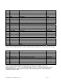
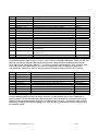
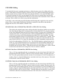
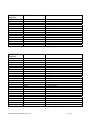
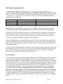
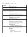
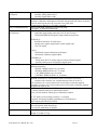
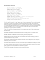
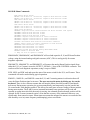
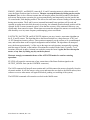
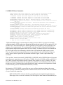
STS-1 Very Broadband Seismometer
Electronics
STS1-E300
User’s Manual
Version 1.20
Metrozet, LLC
21143 Hawthorne Blvd. #456
Torrance, CA 90503
866-823-0339
www.metrozet.com
Copyright, 2008
STS1-E300 User’s Manual, Rev 1.20
1 of 31
Table of Contents
No User-Serviced Parts; Electrical Safety Notice…………………………………
p. 3
Introduction and Instrument Description………………………………………..
p. 4
STS1-E300 Package and Connections……………………………………………
pp. 5-7
STS1-E300 Cabling……………………………………………………………….
pp. 8-11
STS1-E300 Communications………………………………………………………
p. 12
STS1-E300 Specifications………………………………………………………………. pp. 13-14
Module Interchangeability and Scale Factor Conversion……………………………. p. 15
Operation………………………………………………………………………………..
pp. 16
STS1-E300 Command Software……………………………………………………….
p. 17-30
Contact Metrozet……………………………………………………………………….
p. 31
Visit www.metrozet.com for the latest version of this manual
STS1-E300 User’s Manual, Rev 1.20
2 of 31
No User-Serviced Parts
There is no reason to open the instrument case. There are no manual adjustments to make to the
electronics and there are no parts that can be user-serviced. Opening the module (and/or altering
the tamper-indicating seal), without prior approval of Metrozet, will void the product’s
warranty.
Electrical Safety Notice
As with all electrical instruments, potentially lethal potentials can be present on all metal
surfaces, including conductors within any cables. Proper grounding of these elements is
important to minimize these risks. The user of this product is responsible for its installation and
operation in a safe manner, and in accordance with all local requirements for electrical safety.
STS1-E300 User’s Manual, Rev 1.20
3 of 31
Introduction and Instrument Description
Metrozet’s STS1-E300 is an advanced electronics package that provides a modern replacement for the
original Streckeisen “Feedback Electronics” boxes. It matches the outstanding analog performance of
the existing circuitry, while providing a number of enhancements that make installation and operation
of the sensors more efficient, within a modern seismic network. These include digital control of all
sensor parameters (corner frequency and damping, with a new 10 second setup mode), remote digital
control of centering motor operations (including a new, one-step “Auto Center” capability), and a
digitally-controlled diagnostic function that allows remote monitoring of all major instrument state-ofhealth parameters (including critical power supply voltages, boom position, signal output levels, motor
switch state, electronics temperature, and a number of auxiliary, analog and digital input lines). All of
the control and diagnostic functions can be controlled locally (via RS-232, USB, or Ethernet), or
remotely (via Ethernet).
In addition, the STS1-E300 provides a complete calibration capability that includes on-board
generation of velocity or acceleration-equivalent test signals (step, swept-sine, and fixed-frequency
sine) as well as automatic switching of calibration test signals into the standard output signal
connectors (“Auto CAL”). The latter feature eliminates the need for a separate “calibration signal”
recording channel, thus allowing recording of transfer function measurement data (stimulus and
response), from triaxial sensors, within a three-channel data acquisition system. The system also
maintains the existing capability for injection of user-generated, external calibration signals into the
system, through a dedicated connector.
All of the control, diagnostic, and calibration features are implemented in an ultra-reliable, “fail-safe”
manner. The system is automatically re-configured to operate as a strictly analog sensor, following
power-on-reset, or after a pre-determined time without an external command.
The STS1-E300 provides the capability for operation and control of three STS-1 sensors. Single and
dual-axis versions are also available. This new module improves greatly on packaging, relative to the
original electronics. A fully watertight case, along with gastight connectors and cabling, is designed to
eliminate a number of moisture-related effects that have plagued the worldwide fleet of STS-1 sensors.
Metrozet offers cabling with all critical signals distributed within a twisted-pair configuration.
Specifically, Metrozet’s hermetic sensor cable, which is fully-compatible with existing the STS-1
baseplate connector, utilizes a twisted pair configuration for all low-level differential signals. Note that
the original, non-hermetic “orange” cables from Streckeisen do not.
Each STS1-E300 module is trimmed to provide identical performance on any given STS-1 mechanical
sensor. In this way, the electronics are interchangeable between sensors. The exact scalar responsivity
of the sensor can be calculated using the “Metrozet STS1Scale Factor Calculator V1.20” software
applet that is included with the electronics.
In short, the STS1-E300 provides STS-1 users with an improved, and fully-supported, capability for
extending the operating lifetime of the world’s highest performance, broadband seismometers.
Please contact Metrozet if you have any specific questions or requirements.
STS1-E300 User’s Manual, Rev 1.20
4 of 31
STS1-E300 Package and Connections
The STS1-E300 electronics are housed in a watertight, die-cast aluminum package. The use of fullyhermetic connectors (Fischer 105 Series gastight bulkhead receptacles and cable plugs) provides a
significant improvement over the non-hermetic packaging used in the original Streckeisen boxes and
cabling. Figure 1 shows a drawing of the STS1-E300 package with the individual connectors clearly
labeled. Tables 1 through 4 provide a pin-by-pin description of each connector.
E SENSOR
CALIBRATE
N SENSOR
Z SENSOR
STS-1 Very Broadband
SEISMOMETER ELECTRONICS
STS1-E300
metrozet
www.metrozet.com
CONTROL
S/N: STS1-E300-10-003
E SIGNAL
N SIGNAL
Z SIGNAL
Figure 1. STS1-E300 Package.
Note that the three axes are labeled “E”, “N”, and “Z”, in keeping with one popular naming convention
for seismic sensor axes. This convention is maintained throughout the entire system (including the
software commands, described below). This is, however, simply a naming convention. There is
nothing that prevents, for example, one from using three vertical sensors with the STS1-E300 module.
Although all three axes would be “Z” axes in this case, the user would still refer to them as “E”, “N”,
and “Z”, in using the module and its software.
STS1-E300 User’s Manual, Rev 1.20
5 of 31
Pin
Name
Description
Input/Output
1
PDFB+
Proportional Differential Feedback +
Output
2
PDFBProportional Differential Feedback Output
3
IFBIntegral Feedback Output
4
IFB+
Integral Feedback +
Output
5
DEMDemodulator Input
6
DEM+
Demodulator +
Input
7
OSC+
Oscillator +
Output
8
OSCOscillator Output
9
MSWMotor Switch Input
10
MSW+
Motor Switch +
Input
11
MOT Motor Drive Output
12
MOT+
Motor Drive +
Output
13
CALCalibration Coil Output
14
CAL+
Calibration Coil +
Output
15
CASE_GND
Case Ground
Input/Output
16
CASE_GND
Case Ground
Input/Output
17
NC
Unused
18
NC
Unused
19
NC
Unused
20
NC
Unused
21
NC
Unused
22
NC
Unused
23
NC
Unused
24
NC
Unused
25
NC
Unused
26
NC
Unused
27
NC
Unused
Table 1: SENSOR Connectors pinout description. There are separate connections for E, N, and Z sensors. The
connector is Fischer DBPE105Z102-130. Under normal operation these signals are not accessed by the user directly.
Pin
Name
Description
Input/Output
1
BRBBroad Band Velocity Output
2
BRB+
Broad Band Velocity +
Output
3
LPLong Period Acceleration Output
4
LP+
Long Period Acceleration +
Output
5
ANALOG_GND
Analog Ground Reference for Signals
Input/Output
6
BOOM_POSITION
Boom
Output
7
CASE_GND
Case Ground
Input/Output
8
CASE_GND
Case Ground
Input/Output
9
NC
Unused
10
NC
Unused
Table 2: SIGNAL Connectors pinout description. There are separate connections for E, N, and Z sensors. The
connector is Fischer DBPE105A062-130. Nominal full-scale output ranges for BRB+/-, LP+/-, and
BOOM_POSITION are +/- 11.5V (+/-23V differential). BRB+/- and LP+/- are fully-differential outputs, with a
common mode reference voltage defined by ANALOG_GND. BOOM_POSITION is a single-ended signal,
referenced to ANALOG_GND.
STS1-E300 User’s Manual, Rev 1.20
6 of 31
Pin
Name
1
2
3
4
5
6
7
8
9
10
11
12
13
14
15
-15V
+15V
POWER_GND
DIGITAL_GND
DIGITAL_3_3V
EXT_RESET
RS232_TX
RS232_RX
CASE_GND
CASE_GND
OUTPUT_SIGNALOUTPUT_SIGNAL+
AUX_ANALOG_0
AUX_ANALOG_1
AUX_DIGITAL_0
Pin
Name
Description
Input/Output
Input Power Input
Input Power +
Input
Power Supply Ground (Return)
Input/Output
Digital Ground; reference for Digital 3.3V and RS-232
Input/Output
3.3V Digital Power for use by remote modules
Output
Active Low RESET Line for Digital Processor
Input
RS-232 Transmit line
Output
RS-232 Receive Line
Input
Case Ground
Input/Output
Case Ground
Input/Output
Reference for user-selected output signal
Output
User-selected output signal
Output
Auxiliary analog input 0; full-scale range is +/-16V
Input
Auxiliary analog input 1; full-scale range is +/-16V
Input
Auxiliary digital input; Nominal VIH=3.3V;
Input
maximum is 6V
16
AUX_DIGITAL_1
Auxiliary digital input; Nominal VIH=3.3V;
Input
maximum is 6V
17
AUX_ANALOG_GND
Reference for AUX_ANALOG_0 and AUX_ANALOG_1
Input
18
AUX_DIGITAL_GND
Reference for AUX_DIGITAL_0 and AUX_DIGITAL_1
Input
Table 3: CONTROL Connector pinout description. The connector is Fischer DBPE105Z038-130. Input power (+/15V nominal) should be within a range of +/-13V to +/-16V, relative to POWER_GND. RS232_TX, RS_232_RX, and
DIGITAL_GND form a full-duplex RS-232 link (EIA/TIA-232), without hardware handshaking. Most internal
signals can be output on OUTPUT_SIGNAL+/-, via software commands (described below). AUX_ANALOG_0 and
1 are analog inputs with a full-scale range of +/-16V. AUX_DIGITAL_0 and 1 are digital state inputs with
conventional 3.3V CMOS levels. They are diode protected to allow input voltage levels between -2V and +6V.
Description
Input/Output
1
CAL_INExternal Calibration Input Input
2
CAL_IN+
External Calibration Input Input
3
CAL_OUTCalibration Drive Signal Output Output
4
CAL_OUT+
Calibration Drive Signal Output +
Output
5
CAL_GND
Ground reference for CAL_IN+/- and CAL_OUT+/Input/Output
6
CAL_GND
Ground reference for CAL_IN+/- and CAL_OUT+/Input/Output
7
CASE_GND
Case Ground
Input/Output
8
CASE_GND
Case Ground
Input/Output
9
NC
Unused
10
NC
Unused
Table 4: CAL Connector pinout description. The connector is Fischer DBPE105Z062-130. CAL_IN+/- allows
external calibration signals to be injected into the electronics. As discussed below, these can be conditioned to
generate velocity or acceleration-equivalent calibration signals, or they can be directly connected into the sensors’
calibration coils. The calibration drive signal can be connected to the CAL_OUT+/- connections to allow external
monitoring/recording of the calibration stimulus. CAL_GND provides a common mode reference voltage for all of
the calibration signals.
STS1-E300 User’s Manual, Rev 1.20
7 of 31
STS1-E300 Cabling
To maintain fully-hermetic (gastight) performance within the entire system, the cabling utilizes the
proper, sealed mating connectors (Fischer Connectors series 105). Metrozet manufactures and sells a
number of cables for use with the STS1-E300. Note that the SIGNAL, CAL, and CONTROL cables
are normally terminated on only one end (pigtailed) to allow users to terminate them as needed for
connection to their legacy instrumentation. Metrozet can provide custom termination of these cables, if
necessary. Please contact us to discuss your particular requirements.
Each cable is color coded with polyolefin-lined heat shrink tubing that is applied over the end of its
plug(s). There is also a white identification label that is attached to each cable on the end that is
plugged into the STS1-E300 module (“inbound” side).
SENSOR Cable: (Part # 12010-067-20); ORANGE or YELLOW Color Coding
This replaces the original orange sensor cable produced by Streckeisen (which was not sealed).
One end of this 20’ long cable is terminated with a Fischer S105Z102-130+ plug that attaches
to one of the SENSOR connectors on the electronics module. The other end is terminated with
a Fischer S105A038-130+ plug which mates with the standard bulkhead receptacle (Fischer
105A038 Series) that is used on the aluminum ring of the STS-1 sensor baseplate. The cable
(polyurethane-jacketed) consists of 8 twisted pairs of 28 AWG stranded wire (7 strands). There
is a single shield/drain wire that is tied to the body of the connector on the inbound side only
(only on the S105Z102-130+ plug). The shield/drain are NOT (redundantly) connected to the
body of the outbound plug (S105A038-130+). The SENSOR signals are grouped into pairs in
such a way to provide the maximum level of common-mode rejection and the minimum level
of crosstalk. Note that the original orange cables did not use twisted pairs. The details of the
SENSOR cable are listed in Table 5. Note that on some early cable shipments, a yellow colored
boot has been used instead of an orange boot. The two cables are identical.
SIGNAL Cable (Part # 12010-063-20); WHITE Color Coding
This is a 20’ long, pigtailed cable that is terminated on one end with a Fischer S105A062-130+
plug that attaches to the SIGNAL connectors on the electronics module. The other end is left
bare. The cable (polyurethane-jacketed) consists of 4 twisted pairs of 24 AWG stranded wire (7
strands). There is a single shield/drain that is attached to the body of the connector. The details
of the SIGNAL cable are listed in Table 6.
CONTROL Cable (Part # 12010-060-20); BLUE Color Coding
This is a 20’ long, pigtailed cable that is terminated on one end with a Fischer S105Z038-130+
plug that attaches to the CONTROL connector on the electronics module. The other end is left
bare. The cable (polyurethane-jacketed) consists of 9 twisted pairs of 24 AWG stranded wire (7
strands). There is a single shield/drain that is attached to the body of the connector. The details
of the CONTROL cable are listed in Table 7. Note that Metrozet also provides a version of the
CONTROL cable that is terminated on both ends. This cable (Part # 12010-061-20) is used
STS1-E300 User’s Manual, Rev 1.20
8 of 31
with the optional STS1-PTM1 Power and Telemetry Module. This dual cable connects the
shield/drain to body of only the inbound connector
CAL Cable (Part # 12010-065-20); GREEN Color Coding
This is a 20’ long, pigtailed cable that is terminated on one end with a Fischer S105Z067-130+
plug that attaches to the CAL connectors on the electronics module. The other end is left bare.
The cable (polyurethane-jacketed) consists of 4 twisted pairs of 24 AWG stranded wire (7
strands). There is a single shield/drain that is attached to the body of the connector. The details
of the CAL cable are listed in Table 8.
S105Z102-130+
Plug (Inbound)
Pin #
Wire Color
Name
S105A038-130+
(Outbound)
Pin#
1
2
WHITE
BLACK
PDFB+
PDFB-
9
10
3
4
WHITE
BROWN
IFBIFB+
13
12
5
6
WHITE
RED
DEMDEM+
6
7
7
8
WHITE
ORANGE
OSC+
OSC-
5
4
9
10
WHITE
YELLOW
MSWMSW+
1
11
11
12
WHITE
GREEN
MOTMOT+
3
2
13
14
WHITE
BLUE
CALCAL+
14
15
15
16
WHITE
VIOLET
CASE_GND
CASE_GND
8
17
Table 5. Details of SENSOR cable connections. The wires are grouped by twisted pair.
STS1-E300 User’s Manual, Rev 1.20
9 of 31
S105A062-130+
Plug Pin #
Wire Color
Name
1
2
WHITE
BLACK
BRBBRB+
3
4
WHITE
BROWN
LPLP+
5
6
WHITE
RED
ANALOG_GND
BOOM_POSITION
7
8
WHITE
ORANGE
CASE_GND
CASE_GND
9
10
NC
NC
Table 6. Details of SIGNAL cable connections. The wires are grouped by twisted pair.
S105Z038-130+
Plug Pin #
Wire Color
Name
1
2
WHITE
BLACK
-15V
+15V
3
4
WHITE
BROWN
POWER_GND
DIGITAL_GND
5
6
WHITE
RED
DIGITAL_3_3V
EXT_RESET
7
8
WHITE
ORANGE
RS232_TX
RS232_RX
9
10
WHITE
YELLOW
CASE_GND
CASE_GND
11
12
WHITE
GREEN
OUTPUT_SIGNALOUTPUT_SIGNAL+
13
14
WHITE
BLUE
AUX_ANALOG_0
AUX_ANALOG_1
15
16
WHITE
VIOLET
AUX_DIGITAL_0
AUX_DIGITAL_1
17
WHITE
AUX_ANALOG_GND
18
GRAY
AUX_DIGITAL_GND
Table 7. Details of CONTROL cable connections. The wires are grouped by twisted pair.
STS1-E300 User’s Manual, Rev 1.20
10 of 31
S105Z062-130+
Plug Pin #
Wire Color
Name
1
2
WHITE
BLACK
CAL_INCAL_IN+
3
4
WHITE
BROWN
CAL_OUTCAL_OUT+
5
6
WHITE
RED
CAL_GND
CAL_GND
7
8
WHITE
ORANGE
CASE_GND
CASE_GND
9
10
NC
NC
Table 8. Details of CAL cable connections. The wires are grouped by twisted pair.
STS1-E300 User’s Manual, Rev 1.20
11 of 31
STS1-E300 Communications
Communication with the STS1-E300 module is via a native RS-232 interface (EIA/TIA-232
compliant). This asynchronous serial link operates at 9600 baud, 8 data bits, 1 stop bit, no parity.
RS232_TX, RS232_RX, and DIGITAL_GND can be connected to a PC’s COM port (to pins 2, 3, and
5, respectively, on a 9-pin D connector, as shown in Table 9). This forms a full-duplex serial link,
without hardware handshaking.
Signal Name
CONTROL Connector Pin #
PC COM Port 9-Pin D Connector Pin #
RS232_TX
RS232_RX
DIGITAL_GND
7
8
4
2
3
5
Table 9. Details of connection of RS-232 link to PC COM port connector.
Bi-directional communication can be made via one of a number of terminal emulators (including
HyperTerminal, which is included with most modern versions of the Windows operating system).
Note that the PC will need to have (or emulate) a COM port in order to communicate. Many modern
PCs do not have an internal COM port. In this case, the user will need to purchase, for example, a
USB-to-COM port adapter module. These are available at most computer retailers. The COM port
should be set up with the communications parameters listed above.
Metrozet’s External Power and Telemetry Module (STS1-PTM1) can be used to convert the RS-232
interface to USB and Ethernet. The former will allow local control of the system via a laptop and the
latter will allow remote operation within the customer’s seismic network. Please contact Metrozet for
details on this module.
The STS1-E300 recognizes backspace characters as entered through many terminal emulators (such as
HyperTerminal). This is very useful for correcting errors in commands entered into the terminal. Note,
however, that some terminal programs transmit special characters (e.g., CTL-H) for a backspace.
These characters will not be recognized by the STS1-E300.
External RESET
The CONTROL connector contains an External RESET line (CONTROL connector pin 6) that allows
the user to reset the digital processor within the module, should communications or control of the
system become interrupted. This digital RESET process does not affect the analog sensors. Following
RESET, the digital processor will boot up and the communications prompt (described below) will be
on the MAIN menu. The system will come up in SAFE mode following a RESET. The RESET is an
active-LOW input. Its nominal voltage range is between 0 and 3.3V, relative to DIGITAL_GND
(CONTROL connector pin 4). It can be left unconnected for normal operation (as it is pulled-up
internally). However, Metrozet recommends that users connect this to a remotely controlled
digital line (within their digitizer) in order to obtain optimum control of the electronics module.
Because of the pull-up resistor, both standard logic gates, and open-drain drivers, can be used. Note
also that the optional STS1-PTM1 module provides both a mechanical switch, and a fully-isolated,
active-HIGH digital input, for generating the digital RESET. See the STS1-PTM1 User’s Manual for
details.
STS1-E300 User’s Manual, Rev 1.20
12 of 31
Metrozet STS1-E300: Detailed Specifications
Specification
Value
Format
Sensor Control Functions
Electronics supports up to 3 fully-independent sensor channels
Nominally configured as E, N, and Z.
Single and dual-axis versions available
360 seconds, Normal Operation
10 Seconds, Setup
Nominal Damping: 0.707 of critical
Approximately +/-23V Differential for BRB and LP
Approximately +/-11.5V Single-Ended for Boom Position
Exchange of electronics boxes will maintain corner frequency, damping, and scalar
responsivity, to within 1%
Via serial command strings:
Motor Control Functions
Independent control of each sensor’s low corner frequency:
360 sec Default, 10 sec in Setup Mode
Independent control of each sensor’s low corner frequency damping:
0.707 of critical Default, undamped in Setup Mode
Via serial command strings:
Calibration Functions
Independent monitoring of each sensor’s motor limit switch
Independent control of each sensor’s centering motor:
ON/OFF/Direction
One-step “Auto Center” for each sensor
Works seamlessly with both horizontal and vertical STS-1 sensors
Via serial command strings:
Nominal Low Corner
Frequencies
Analog Output Ranges
Uniformity
Diagnostic Functions
Direct connection of external signals to sensor CAL coils
Signal conditioning circuitry for converting raw CAL signals into
acceleration or velocity-equivalent stimuli
External input of remote CAL signals into signal conditioning circuit
Internal generation of CAL signals via 16-bit DAC
Internally-generated step, sine sweep, and sine (0.01 Hz, 0.1 Hz, and 1 Hz)
Optional “Auto CAL” function:
CAL Stimulus connected to E SIGNAL connector
E or N sensor output connected to N SIGNAL connector
Z sensor output connected to Z SIGNAL connector
Via serial command strings:
Digitization of internal signals via 24-bit ADC (remote diagnostics)
Connection of internal signals to analog differential output lines (local diagnostics)
Signals Monitored:
E/N/Z BRB+/E/N/Z LP+/E/N/Z Boom Position
E/N/Z Motor Limit Switch State
Analog Power +/- (regulated power used by sensors)
Input Power +/Module Temperature (via internal temperature sensor)
STS1-E300 User’s Manual, Rev 1.20
13 of 31
Diagnostic Functions
(continued)
Fail-Safe Mode
Native Command Interface
Connector Names (quantity)
and Functions
DAC Voltage
Auxiliary Analog Input 0 and 1
Auxiliary Digital Input 0 and 1
All sensors set to 360 second corner frequency, with damping engaged
All motor, calibration, and diagnostic functions disconnected from sensor electronics
Fail-safe entered upon power-up (or power reset), after 3600
second inactivity timeout, or via remote command
RS-232, 9600 baud, 8 data bits, 1 stop bit, No parity
Full-duplex, no hardware handshaking
SIGNAL (3)
Individual signal output connectors for E, N, and Z sensors
Differential BRB and LP signals, Single-ended boom position
SENSOR (3):
Individual connectors for each sensor
Analog sensor signals, digital motor control signals, and
CAL coil signals
CAL(1):
Differential external calibration signal inputs
and internal calibration signal outputs
Connector Types
CONTROL(1):
Power inputs, RS-232, analog output of selected internal signals,
Auxiliary analog inputs, and auxiliary digital inputs
All are Fischer Connectors, Series DBPE105, fully hermetic
bulkhead receptacles:
SIGNAL: DBPE105A062-130, 10-contact
SENSOR: DBPE105Z102-130, 27-contact
CAL: DBPE105Z062-130, 10-contact
CONTROL: DBPE105Z038-130, 18-contact
Standard Cabling
SIGNAL: S105A062-130+ on polyurethane cable (4-twisted pairs with shield), pigtailed
SENSOR: S105Z102-130+ on polyurethane cable (8-twisted pairs with shield),
terminated with S105A038-130+ (standard baseplate connector on STS-1)
CAL: S105Z062-130+ on polyurethane cable (4-twisted pairs with shield), pigtailed
CONTROL: S105Z038-130+ on polyurethane cable (9-twisted pairs with shield), pigtailed
Standard cable length: 20 feet
Input Power
+/-15V nominal; +/-13V to +/-16V Limits
+/-250 mA nominal, with power stabilization enabled
+160/-145 mA nominal, without power stabilization enabled
Power Stabilization
Physical
10-33V input (reverse-polarity protection, overvoltage
protection, and fusing) available with Metrozet’s External Power
and Telemetry Module (STS1-PTM1)
Automatic load current stabilization circuit provides for constant
power dissipation within the package
Use of power stabilization is optional
Package Size: 12.6” x 12.6”x 4.8” (32 cm x 32 cm x 12.2 cm)
Weight:17 pounds (7.7 kg)
STS1-E300 User’s Manual, Rev 1.20
14 of 31
Module Interchangeability and Scale Factor Conversion
The STS1-E300 is designed and manufactured to provide identical performance from module to
module. Specifically, the feedback components are carefully trimmed to a uniformity of under 1%.
This allows STS1-E300 modules to be interchanged without significantly affecting the sensor’s
response (either its scalar responsivity, or its frequency response). This uniformity is intended to
simplify long-term maintenance of the sensors.
However, due to siginificant variations in the original manufacturing process (by Streckesien), the
scalar responsivity (V/m/sec at the BRB output, and V/gal at the LP output) of any given mechanical
sensor mated with the STS1-E300 will exhibit some variation (from the nominal 2400 V/m/sec [BRB]
and 80 V/gal [LP] that Streckeisen attempted to provide). In fact, there will be a systemic bias related
to the orientation of the sensor: vertical sensors will have a higher scalar responsivity, and horizontal
sensors will have a lower responsivity.
Fortunately, the exact scalar responsivity of any sensor connected to the STS1-E300 can be accurately
determined, without further physical measurement. Using an applet (“Metrozet STS1Scale Factor
Calculator V1.20”), the operator can determine the scalar responsivity of any sensor, given the original
factory “Seismometer Calibration Sheet” values. This software applet is shipped with the electronics
module. It is also available for download from www.metrozet.com . Run the “setup” file to install this
applet to any Windows PC.
Note that the expected variation in frequency response (specifically the low corner frequency and its
damping ratio), caused by the new electronics, is quite small. In any event, the exact frequency
response (poles and zeros) for any sensor can be determined easily, given the extensive calibration
capabilities provided within the STS1-E300 module.
STS1-E300 User’s Manual, Rev 1.20
15 of 31
Operation
Operating the STS1-E300 involves a few simple steps:
1. Connect the +15V/-15V/POWER_GND wires in the CONTROL cable to a high-quality,
regulated power supply, capable of providing at least 0.5A. It is important to note that many
commercial power supply modules (including DC-DC converters) can exhibit start-up
problems at high load. It is recommended that the user provides a power supply with a current
rating that is at least 2X that which is required by the electronic module. Metrozet recommends
an Agilent E32620A (Dual output, 1A), however, many commercial power supplies will
suffice. Note that Metrozet’s External Power and Telemetry Module (STS1-PTM1) contains an
internal power supply that will convert unregulated input power (10-33V DC) into wellregulated +/-15V, for use with the STS1-E300.
2. With the power supply turned OFF, connect the COMNTROL cable to the STS1-E300 module.
3. Assuming that one is using a local PC for command and control, connect the RS-232 leads of
the CONTROL cable to the COM port of a PC. Or, if using the STS1-PTM1 module, connect
to the PC using either the USB or Ethernet connection. Launch a terminal emulator on the PC.
4. With the power OFF, connect the SENSOR cables between each of the STS-1 mechanical
sensors and the STS1-E300 module’s SENSOR connectors. In a normal, triaxial application,
the two horizontal sensors should be connected to the E and N channels, and the vertical sensor
should be connected to the Z channel. This will allow the centering motor control to operate
seamlessly.
5. Connect the SIGNAL cables between the STS1-E300 module and the recording system.
6. Turn on the power supply. The quiescent current draw should be approximately +160 mA/-145
mA (at +/-15V) if the power stabilization is not enabled. With power stabilization enabled, the
quiescent current draw should be +/-250 mA.
Note: power stabilization is an optional feature (set by factory-installed jumpers) that provides
a constant current (and hence power) consumption within the STS1-E300 module (regardless
of dynamic signals). The power stabilization maintains a nominal current draw of +/-250 mA
at +/-15V. This is exclusive of any current consumed by relays (which are energized only
during setup, calibration, and centering motor control, and not during normal operation). In
V1.20, the default is for power stabilization NOT to be enabled. Please contact Metrozet for
details on how to enable it.
7. Observe that the command prompt “STS-1 Main Menu:MAIN>” is visible in the terminal
window. Hit “Enter” once or twice (and observe that a new command prompt is generated each
time) to verify that the communication link is active.
The sensor is now operational.
Note: Turn OFF power from the system before connecting or disconnecting any cable from the
STS1-E300 module.
STS1-E300 User’s Manual, Rev 1.20
16 of 31
STS1-E300 Command Software
Control of the STS1-E300 is via a menu-drive command structure. The commands are NOT casesensitive. At power-up, the system enters the MAIN menu. This is predominantly a gateway to four
other menus (SENSOR, MOTOR, CALIBRATE, DIAGNOSTIC). The complete list of commands
(available by typing “?” followed by “Enter”) are:
MAIN Menu Commands:
SENSOR: Selects Sensor Control Menu
MOTOR: Selects Motor Control Menu
CALIBRATE: Selects Calibration Control Menu
DIAGNOSTIC: Selects Diagnostic Control Menu
SAFE: Puts System Into Default Analog Measurement Mode
ENABLE######: Enable System Control(###### is Password)
DISABLE: Disable System Control
STATUS: Print system status info
?: Help for info on specific command
Within the MAIN menu, the sensor is in “SAFE” mode. In this mode, the system operates as a purely
analog sensor. All connections to the various diagnostic and control systems in the module are broken.
In SAFE mode, the system operates exactly as the original Streckeisen Feeback Electronics would.
Note that physical connection to the sensor’s CAL coils is also broken in SAFE mode. In this way, the
sensor is probably better isolated than with the original electronics. SAFE mode will be the normal
recording mode for the sensor.
Other operating modes (accessed via the SENSOR, MOTOR, CALIBRATE, and DIAGNOSTIC
menus) are meant to be temporary, and they can only be accessed once control of the system is
“enabled”. The ENABLE###### command (where ###### is a six character password) must be
entered to allow access to these other menus.
In V1.20 of the electronics module, the password is “abcdef”. One enters “enableabcdef” to
enable the system. Once enabled, the system turns ON relay control power within the module
(required to energize the relays used temporarily within the other operating modes) and it
provides software access to the other menus.
Entering “DISABLE” will remove relay power and will block software access to the other menus.
Entering “SAFE” at any time (and from any other menu) will also remove relay power. It will return
the user to the MAIN menu and block access to the other menus (until the system is re-enabled).
Within any menu, there is also an activity timer that keeps track of the number of seconds since the last
command has been entered. After 3600 seconds (1 hour) without a command, the system enters SAFE
mode. 3600 seconds is sufficient for even the most time-consuming operations (e.g., various
calibration sequences) to be performed.
STS1-E300 User’s Manual, Rev 1.20
17 of 31
SAFE mode is designed to provide two levels of safety. First, by removing power from the many
relays used within the module (to enable connections to the sensor for various control and
diagnostic functions), the system CANNOT (inadvertently) actuate any of these relays. This will
prevent the sensors from being placed into an undesired operating mode or allow an electrical
connection that might introduce noise. Second, by requiring an explicit ENABLE command to be
entered, the system is further protected from unintended commands being able to control the
operation of the module.
Entering SAFE mode also causes the STS1-E300 processor to re-calibrate its internal RS-232 baud rate
generator. If the STS1-E300 is operated over a wide temperature range, it is possible that the module’s
baud rate can drift relative to that of the communications system to which it is connected. If this
happens the user may see “garbled” characters being printed out from the module. In this case the user
simply enters SAFE mode to re-calibrate the baud rate. This should allow normal communication to
resume. As an additional safety measure the STS1-E300 will also reset its baud rate if it receives
improper commands or whenever the inactivity timer (3600 seconds) is tripped. In this way, reliable
communications are ensured without any user specific user input.
The “STATUS” command prompts the system to print its serial number, software version number, and
the configuration of its axes. The nominal (factory default) configuration is for the E and N axes to be
horizontal sensors and the Z axis to be a vertical sensor. This information is used during centering
motor control. If necessary (say in the case of all vertical sensors), the configuration can be changed
via a set of hidden commands. Please contact Metrozet for details.
STS1-E300 User’s Manual, Rev 1.20
18 of 31
SENSOR Menu Commands:
E10: Set E Sensor to 10 Second Mode
E360: Set E Sensor to 360 Second Mode
EDAMP: Engage E Sensor Damping
EUNDAMP: Remove E Sensor Damping
N10: Set N Sensor to 10 Second Mode
N360: Set N Sensor to 360 Second Mode
NDAMP: Engage N Sensor Damping
NUNDAMP: Remove N Sensor Damping
Z10: Set Z Sensor to 10 Second Mode
Z360: Set Z Sensor to 360 Second Mode
ZDAMP: Engage Z Sensor Damping
ZUNDAMP: Remove Z Sensor Damping
DEFAULT: Restores All Sensors to 360 Seconds, with Damping Engaged
STATUS: Prints Configuration of Sensors
SAFE: Puts System Into Default Analog Measurement Mode
RETURN: Return to Previous Menu
?: Help for info on specific command
E10, N10, and Z10 set the E, N, and Z sensors into a 10-second setup mode. This is useful for quickly
settling the electronics following power-ON, or for installation and leveling. Note that this mode
replaces the original 20-second mode in the STS-1 Feedback Electronics boxes. In nearly all respects,
a 10-second operating model is preferable for installation and setup (as it has faster-settling transients).
In that the vast majority of STS-1 users operate in 360-second mode (and not 20-second mode),
elimination of a 20-second mode is acceptable.
E360, N360, and Z360 will change the sensors’ low frequency corner back to 360 seconds (normal
operating mode)
EUNDAMP, NUNDAMP, and ZUNDAMP will remove damping from the E, N, and Z sensors.
EDAMP, NDAMP, and ZDAMP will restore damping (normal operating mode).
With the STS1-E300, users will want enter 10-second mode and will remove damping in order to
perform installation leveling operations.
The STATUS command will provide information about the current configuration (corner frequency
and damping state) of each sensor.
The SAFE command will place each sensor in its normal 360-second/Damped recording mode. It will
also remove relay power and return the user back to the MAIN menu (where software access to other
menus will again be blocked, pending a re-enabling of the system).
The RETURN command will return the user back to the MAIN menu.
STS1-E300 User’s Manual, Rev 1.20
19 of 31
MOTOR Menu Commands:
ESW: Read E Motor Switch
EMOVE+: Run E Motor in + Direction; Outputs E Boom Position on ADC
EMOVE-: Run E Motor in - Direction; Outputs E Boom Position on ADC
NSW: Read N Motor Switch
NMOVE+: Run N Motor in + Direction; Outputs N Boom Position on ADC
NMOVE-: Run N Motor in - Direction; Outputs N Boom Position on ADC
ZSW: Read Z Motor Switch
ZMOVE+: Run Z Motor in + Direction; Outputs Z Boom Position on ADC
ZMOVE-: Run Z Motor in - Direction; Outputs Z Boom Position on ADC
STOP: Stops All Motors
DEFAULT: Stops All Motors and Disconnects All Motor Switches from System
EBOOMADC: Reads E Boom Position on ADC
NBOOMADC: Reads N Boom Position on ADC
ZBOOMADC: Reads Z Boom Position on ADC
EBOOMCTL: Outputs E Boom Position on Control Connector
NBOOMCTL: Outputs N Boom Position on Control Connector
ZBOOMCTL: Outputs Z Boom Position on Control Connector
DISCCTL: Disconnects Boom Position from Control Connector
STATUS: Prints Status of Control Connection to Boom Position
EAUTOCTR: Runs Autocenter on E Sensor
NAUTOCTR: Runs Autocenter on N Sensor
ZAUTOCTR: Runs Autocenter on Z Sensor
SAFE: Puts System Into Default Analog Measurement Mode
RETURN: Return to Previous Menu
?: Help for info on specific command
EBOOMADC, NBOOMADC, and ZBOOMADC will read and report the E, N, and Z Boom Position
voltage, using the internal analog-to-digital converter (ADC). This is used typically for remote
diagnostic operation.
EBOOMCTL, NBOOMCTL, and ZBOOMCTL will connect the analog Boom Position signal (from
either the E, N, or Z sensor) across the OUTPUT_SIGNAL+/- lines of the CONTROL connector. This
can be used for local diagnostic operations, using a scope or DMM.
ESW, NSW, and ZSW read and report the state of the motor switch for the E, N, and Z sensor. These
commands will not be needed during typical operation.
EMOVE+, NMOVE+, and ZMOVE+ starts the E, N, and Z centering motors in a direction that will
cause the Boom Position signal to increase. The user can stop the motor by hitting any key on the
keyboard. There is also a timeout counter that will stop the motor after 600 seconds of (attempted)
movement. During motor operation, the system automatically (and temporarily) sets the sensors into
10-second mode, with damping enabled. This allows for much more accurate reading of boom position
during motor motion. The E and N sensor (assumed horizontal) boom positions will be read and
reported at regular intervals while the motor is moving. An estimated (dead-reckoned) position will be
reported for the Z sensor (assumed vertical). Note that the accuracy of the estimated value may vary
significantly from sensor-to-sensor. When motor movement has stopped, the sensors are restored to the
state that they were in (corner frequency and damping) prior to movement.
STS1-E300 User’s Manual, Rev 1.20
20 of 31
EMOVE-, NMOVE-, and ZMOVE- starts the E, N, and Z centering motors in a direction that will
cause the Boom Position signal to decrease. The user can stop the motor by hitting any key on the
keyboard. There is also a timeout counter that will stop the motor after 600 seconds of (attempted)
movement. During motor operation, the system automatically (and temporarily) sets the sensors into
10-second mode, with damping enabled. This allows for much more accurate reading of boom position
during motor motion. The E and N sensor (assumed horizontal) boom positions will be read and
reported at regular intervals while the motor is moving. An estimated (dead-reckoned) position will be
reported for the Z sensor (assumed vertical). Note that the accuracy of the estimated value may vary
significantly from sensor-to-sensor. When motor movement has stopped, the sensors are restored to the
state that they were in (corner frequency and damping) prior to movement.
EAUTOCTR, NAUTOCTR, and ZAUTOCTR initiate a one-step, iterative, autocenter algorithm on
the E, N, and Z sensors. The algorithm drives the Boom Position to a voltage between -0.20V and
+0.20V through an iterative process. These routines temporarily set the sensors to 10-second/damped
state, and restore them to their original configuration when finished. The algorithm will attempt to
move the boom approximately ½ of the way to the target on each iteration, automatically repeating
until the target is reached, or the number of iterations has reached 20 (the limit). Typically, 5 or 6
iterations (achieved in under 1 minute) are needed to center the boom. Again, the user can stop the
motor, at any time, by hitting any key on the keyboard.
Metrozet strongly recommends the use of the AUTOCTR modes for routine centering
operations.
STATUS will report the current state of any connections of the Boom Position signals to the
OUTPUT_SIGNAL lines (on the CONTROL connector).
The SAFE command will stop all motor motion and it will disconnect the motors electrically from the
electronic module. It will also remove relay power and return the user back to the MAIN menu (where
software access to other menus will again be blocked, pending a re-enabling of the system).
The RETURN command will return the user back to the MAIN menu.
STS1-E300 User’s Manual, Rev 1.20
21 of 31
CALIBRATE Menu Commands:
STEP: Internal CAL Source Outputs 0V/+7.5V/0V Step for 100/500/500 Seconds
SWEEP: Internal CAL Source Outputs LF and HF Sweep for 1382 Seconds
0.01HZSINE: Internal CAL Source Outputs 0.01Hz Sine for 1000 Seconds
0.10HZSINE: Internal CAL Source Outputs of 0.10Hz Sine for 100 Seconds
1.00HZSINE: Internal CAL Source Outputs of 1.00Hz Sine for 100 Seconds
EXTCALCONNECT: External CAL Input+/- Attached Directly to E/N/Z CAL Coils
EXTCALVELOCITY: External CAL Input+/- Velocity Equivalent Source Connected to E/N/Z
CAL Coils
EXTCALACCELERATION: External CAL Input+/- Acceleration Equivalent Source Connected to
E/N/Z CAL Coils
EXTCALDISCONNECT: External CAL Input+/- Disconnected from E/N/Z CAL Coils
INTCALVELOCITY: Internal Velocity Equivalent CAL Source Connected to E/N/Z CAL Coils
INTCALACCELERATION: Internal Acceleration Equivalent CAL Source Connected to E/N/Z
CAL Coils
INTCALDISCONNECT: Internal CAL Source Disconnected from E/N/Z CAL Coils
EZSIGNALOUT: CAL/E/Z Signals Connected to E/N/Z SIGNAL Connectors, Respectively
NZSIGNALOUT: CAL/N/Z Signals Connected to E/N/Z SIGNAL Connectors, Respectively
DEFAULTSIGNALOUT: Restore Default SIGNAL Connections
EXTCALOUT: External CAL Input+/- Drive Signal Connected to CAL Output+/INTCALOUT: Internal CAL Source Drive Signal Connected to CAL Output+/DISCCALOUT: CAL Source Disconnected from CAL Output+/STATUS: Prints Status of Control Connection
SAFE: Puts System Into Default Analog Measurement Mode
RETURN: Return to Previous Menu
?: Help for info on specific command
STEP and SWEEP initiate an internal digital-to-analog converter (DAC) to generate an automatic
calibration stimulus. STEP produces an upward and downward step sequence (500 seconds at 0V, 500
seconds at 6.0V and 500 seconds at 0V. SWEEP generates a low frequency sweep (from high to low
frequency, from approximately 128 second period to well above 1500 second period) followed by a
high frequency stepped sine sequence (from 0.5 Hz to 40 Hz). The former will serve as a stimulus for
the 360-second corner of the instrument, while the latter will elucidate the high frequency corner.
There is a 500 second quiescent period between sweeps, and prior to the start of the low-frequency
sweep. Figure 2 shows a plot of the step function waveform. Figure 3 shows a plot of the sweep
waveform.
There are three, internal sine stimuli (1.00HZSINE, 0.10HZSINE, and 0.01HZSINE) that will generate
mono-frequency, quasi-sine waves (100 cycles of 1.00Hz, 10 cycles of 0.10 Hz, and 10 cycles of 0.10
Hz). These are useful for looking at specific response of the sensors at 1.00, 0.10, and 0.01 Hz. Note
that due to limitations in the low-power microprocessor, and DAC, used within the module, these are
not pure sine waves. Therefore these signals should not be used to measure critical parameters related
to sensor linearity (such as Total Harmonic Distortion, or THD).
By themselves, STEP, SWEEP, or any of the sine waves will not stimulate anything in the sensor.
Unless explicitly commanded, nothing will be connected to the sensor CAL coils. There are a number
of ways to make this connection.
INTCALVELOCITY will route the above, internally-generated signals through a high-pass
filter stage (with a 1 msec time constant). The filter output is then connected simultaneously to
STS1-E300 User’s Manual, Rev 1.20
22 of 31
the CAL coils of the three sensors. This provides for a velocity-equivalent stimulus of the
sensor. In this case, the response of the BRB outputs will be flat over the passband of the
sensor. As an example, Figure 4 shows the stimulus and BRB response for a velocityequivalent STEP function. Figure 5 shows the response from a velocity equivalent SWEEP
function
INTCALACCELERATION will route the above, internally-generated signals through a DCcoupled attenuator. The attenuator output is then connected simultaneously to the CAL coils of
the three sensors. This provides for an acceleration-equivalent stimulus of the sensor. In this
case, the response of the LP outputs will be flat over the passband of the sensor.
INTCALDISCONNECT will disconnect the internally-generated calibration signals from the
sensors’ CAL coils.
Note: It is recommended to use velocity-equivalent signals when calibrating the standard BRB
(velocity-sensitive) outputs. Similarly, it is recommended to use acceleration-equivalent signals when
calibrating the standard LP (acceleration-sensitive) outputs.
In certain cases, users may want to generate calibration stimulus signals externally:
EXTCALVELOCITY and EXTCALACCELERATION will route external signals from the
CAL_IN+/- lines of the CAL connector, through the AC and DC-coupled stages, respectively.
The conditioned signals will be connected simultaneously to the CAL coils of the three sensors.
This will generate velocity-equivalent and acceleration-equivalent versions of the external
signal. When generating acceleration equivalent signals, the external signal should be limited to
approximately +/-7.5V to avoid signal clipping within the electronics.
EXTCALCONNECT will make a direct connection between the CAL_IN+/- lines and the
sensors’ CAL coils. There is no attenuation, so the user should take great care to avoid
overdriving the sensor (an attenuation of at least 2500X, for a drive amplitude of +/- 7.5 V, is
recommended to avoid clipping within the electronics signal chain).
EXTCALDISCONNECT will disconnect the externally-injected calibration signals from the
sensors’ CAL coils.
Note: Typically there will be a small transient response observed when any signals are connected to
the CAL coils (via INTCALVELOCITY, INTCALACCELERATION, EXTCALVELOCITY,
EXTCALACCELERATION, or EXTCALCONNECT. For this reason, it is recommended that the
user wait for a period of approximately 500 seconds, after initiating CAL coil connection, before
beginning CAL stimulus.
STS1-E300 User’s Manual, Rev 1.20
23 of 31
In some cases, users may want to record both stimulus and response signals, from a triaxial sensor,
using a recording system with only three channels:
EZSIGNALOUT will route the calibration stimulus signal (either internnaly or externallygenerated, depending upon whether the INTCAL… or EXTCAL… modes are enabled) to the E
SIGNAL connector. It will route the same signal across both the BRB and LP outputs. The E
sensor signals outputs will be routed to the N SIGNAL connector. The Z sensor outputs will
remain connected to the Z SIGNAL connector.
NZSIGNALOUT will route the calibration stimulus signal (either internnaly or externallygenerated, depending upon whether the INTCAL… or EXTCAL… modes are enabled) to the E
SIGNAL connector. It will route the same signal across both the BRB and LP outputs. The N
sensor signals outputs will remain connected to the N SIGNAL connector. The Z sensor
outputs will remain connected to the Z SIGNAL connector.
Two calibration runs, one with EZSIGNALOUT and the next with NZSIGNALOUT will allow
all channels to be calibrated.
DEFAULTSIGNALOUT will restore the system to the standard output mode (E to E, N to N,
and Z to Z).
INTCALOUT will route the internally-generated calibration signals to the CAL_OUT+/- lines.
EXTCALOUT will route the externally-injected (via CAL_IN+/-) calibration signals to the
CAL_OUT+/- lines.
DISCCALOUT will disconnect all signals from the CAL_OUT+/- lines.
STATUS will report the current connections within the calibration hardware
The SAFE command will disconnect the sensor CAL coils from all signals. It will disconnect the
CAL_IN+/- lines from the calibration hardware in the module and will disconnect all signals from the
CAL_OUT+/- lines. The SIGNAL outputs (if changed via the EZSIGNALOUT or NZSIGNALOUT
commands) will be set back to their normal operating states (E to E, N to N, and Z to Z). It will also
remove relay power and return the user back to the MAIN menu (where software access to other
menus will again be blocked, pending a re-enabling of the system).
The RETURN command will return the user back to the MAIN menu.
STS1-E300 User’s Manual, Rev 1.20
24 of 31
Note Regarding CAL signal Polarity
Within the passband of the sensor, the response of a VERTICAL STS-1 sensor with the STS1-E300
module will be in phase with the CAL stimulus signal. The HORIZONTAL sensor’s response will be
180 degrees out of phase. This is consistent with the operation of the original sensors. It is a
consequence of the design of the STS-1 sensor and the decision to provide “equivalent” channels in
each electronics module. The user will need to note this difference within their own data systems.
Frequency Response Analysis
The major reason for any calibration sequence is to measure or validate the frequency response of a
sensor. There are a number of possible methods for analyzing recorded stimulus/response data in order
to determine the frequency response (poles/zeros). Metrozet is currently developing a modern software
applet (STS1-CALEX-EW; based upon a recursive, time-domain filtering technique developed and
refined by Professor Erhard Wielandt) that will automatically analyze recorded data (in standard
seismic data formats) in order to generate the exact poles and zeros of the STS-1 sensor. Please contact
us for details.
STS1-E300 User’s Manual, Rev 1.20
25 of 31
Figure 2. Internal STEP calibration function. This is recorded data. The ringing on at the rising
and falling edges is simply an artifact of the digital filter used in our data acquisition system.
Figure 3. Internal SWEEP calibration function. This consists of a low frequency sweep and a
high frequency stepped sine (0.5 to 40 Hz).
STS1-E300 User’s Manual, Rev 1.20
26 of 31
Figure 4. Velocity-Equivalent STEP Response. This is recorded data. Top panel is stimulus
signal from internal STEP function. This signal is fed through velocity equivalent circuit into the
CAL coils of sensors. Middle panel is the BRB output from the Z Sensor. Bottom panel shows a
zoomed view of the step onset. The ringing (specifically its period and amplitude decay rate) is
related to the high frequency corner and damping of the STS-1 sensor’s response (nominally at
10 Hz).
STS1-E300 User’s Manual, Rev 1.20
27 of 31
Figure 5. Velocity Equivalent SWEEP Response. This is recorded data. Top panel is stimulus
signal from internal SWEEP function. This signal is fed through velocity equivalent circuit into
the CAL coils of sensors. Middle panel is the BRB output from the Z Sensor. Bottom panel shows
a zoomed view of the response during the stepped sine portion of the calibration.
STS1-E300 User’s Manual, Rev 1.20
28 of 31
DIAGNOSTIC Menu Commands:
EBRB+ADC: Read E BRB+ on ADC
EBRB-ADC: Read E BRB- on ADC
ELP+ADC: Read E LP+ on ADC
ELP-ADC: Read E LP- on ADC
EBOOMADC: Reads E Boom Position on ADC
NBRB+ADC: Read N BRB+ on ADC
NBRB-ADC: Read N BRB- on ADC
NLP+ADC: Read N LP+ on ADC
NLP-ADC: Read N LP- on ADC
NBOOMADC: Reads N Boom Position on ADC
ZBRB+ADC: Read Z BRB+ on ADC
ZBRB-ADC: Read Z BRB- on ADC
ZLP+ADC: Read Z LP+ on ADC
ZLP-ADC: Read Z LP- on ADC
ZBOOMADC: Reads Z Boom Position on ADC
AUXANALOG0: Read AUX 0 Input on ADC
AUXANALOG1: Read AUX 1 Input on ADC
DACADC: Read DAC Voltage on ADC
ANALOGPWR+ADC: Read Analog Power+ on ADC
ANALOGPWR-ADC: Read Analog Power- on ADC
INPUTPWR+ADC: Read Input Power+ on ADC
INPUTPWR-ADC: Read Input Power- on ADC
TEMPERATUREADC: Read Temperature on ADC
AUXDIGITAL0: Reports State of Input Signal on AUX Digital Input 0
AUXDIGITAL1: Reports State of Input Signal on AUX Digital Input 1
EBRB+CTL: Outputs E BRB+ on Control Connector
EBRB-CTL: Outputs E BRB- on Control Connector
ELP+CTL: Outputs E LP+ on Control Connector
ELP-CTL: Outputs E LP- on Control Connector
EBOOMCTL: Outputs E Boom Position on Control Connector
NBRB+CTL: Outputs N BRB+ on Control Connector
NBRB-CTL: Outputs N BRB- on Control Connector
NLP+CTL: Outputs N LP+ on Control Connector
NLP-CTL: Outputs N LP- on Control Connector
NBOOMCTL: Outputs N Boom Position on Control Connector
ZBRB+CTL: Outputs Z BRB+ on Control Connector
ZBRB-CTL: Outputs Z BRB- on Control Connector
ZLP+CTL: Outputs Z LP+ on Control Connector
ZLP-CTL: Outputs Z LP- on Control Connector
ZBOOMCTL: Outputs Z Boom Position on Control Connector
AUXANALOG0CTL: Outputs AUX 0 Input on Control Connector
AUXANALOG1CTL: Outputs AUX 1 Input on Control Connector
DACCTL: Outputs DAC Voltage on Control Connector
ANALOGPWR+CTL: Outputs Analog Power+ on Control Connector
ANALOGPWR-CTL: Outputs Analog Power- on Control Connector
INPUTPWR+CTL: Outputs Input Power+ on Control Connector
INPUTPWR-CTL: Outputs Input Power- on Control Connector
TEMPERATURECTL: Outputs Temperature on Control Connector
DISCCTL: Disconnects Signals from Control Connector
STATUS: Prints Status of Control Connection
SAFE: Puts System Into Default Analog Measurement Mode
RETURN: Return to Previous Menu
?: Help for info on specific command
These commands allow the user to monitor the voltage level of a number of signals within the system.
Commands ending in “ADC” will measure and report the value of the selected signal via the on-board
ADC (with +/-16V range). Commands ending in “CTL” will physically connect the selected signal to
STS1-E300 User’s Manual, Rev 1.20
29 of 31
the OUTPUT_SIGNAL+/- lines on the CONTROL connector. Note that these physical connections
will remain until DISCCTL or SAFE is entered (or until the activity timeout is reached).
DISCCTL disconnects all signals from the OUTPUT_SIGNAL+/- lines on the CONTROL connector.
The purpose of most of the command names is relatively obvious. However:
ANALOG_POWER+/- refer to the regulated voltages used by the analog sensors (+/-12V
nominal)
INPUTPWR+/- refer to the voltage levels of the input power (+/-15V nominal)
AUXANALOG0/1 refer to the voltage levels of the auxiliary analog signals being injected
through dedicated lines within the CONTROL connector. Again, these signals should have a
full-scale range between +/-16V.
AUXDIGITAL0/1 refer to the digital levels of the auxiliary digital signals being injected
through dedicated lines within the CONTROL connector. Recording such levels might be
useful, for example, to see if an intrusion detection switch has been actuated on the entrance to
the seismic vault. Again, these inputs are protected, but the digital levels should be between
-2V and +6V.
TEMPERATURE refers to a low-resolution temperature sensor (LM35) that is mounted within
the electronics box. It is surely at a higher temperature than the ambient temperature in the
vault.
SAFE disconnects all signals from the diagnostic system and from the OUTPUT_SIGNAL+/- lines. It
will also remove relay power and return the user back to the MAIN menu (where software access to
other menus will again be blocked, pending a re-enabling of the system).
The RETURN command will return the user back to the MAIN menu.
STS1-E300 User’s Manual, Rev 1.20
30 of 31
Contact Metrozet
If there are any questions, problems, or further needs regarding the STS1-E300 Electronics, please
contact us.
Metrozet
21143 Hawthorne Blvd. #456
Torrance, CA 90503
866-823-0339
[email protected]
www.metrozet.com
STS1-E300 User’s Manual, Rev 1.20
31 of 31