1
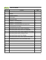
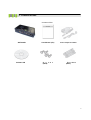
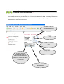
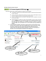
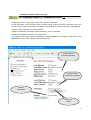
ANT-‐4000D H.264 1080P60 HD VIDEO DECODER User Manual Ver. 1.0 FW Version up to 203.26 1 Safety Precautions We appreciate you purchasing the ANT-4000D. Before installing the product, please read the following carefully. Make sure you turn off the power before installing the ANT-4000D. Do not install under the direct sunlight or in dusty areas. Make sure you use the product within the temperature and humidity specified in the specification. Do not operate the product in presence of vibration or strong magnetic fields. Do not put electrically conducting materials in the ventilation hole. Do not open the top cover of the product. It may cause a failure or electric shock from the components. To prevent the unit from overheating, make sure you keep the ventilation holes at the top least 10cm from any other object. Also allow air underneath the unit and do not obstruct vent holes Make sure the mains voltage is correct (220V/110V) before connecting the power adapter supplied in the box (12V DC output). Do not obstruct ventilation holes above and below the server box. Rubber feet are provided to allow air flow below the server case , in addition to outlet holes at the top of the case. 2 Table of Contents Section Contents Pages 1 About this Manual 4 2 Features 4, 5 3 Contents of the Box 6 4 Panel Layout 7,8 5 Quick Start Guide 9 6 Installation- Connecting Video 10 7 Installation- Connecting Audio 10 8 Installation- Connecting Network and Serial Ports 10 9 Powering up and LED status 11 10 Web based System setup- System Configuration 12 11 Web based System setup- Serial Port Configuration 13 12 Web based System setup-Firmware upgrade & S/W images 14 13 Web based System setup- Streaming Control 15 14 Web based System setup- Save Changes 16 15 Web based System setup- Reboot System-Factory Reset 17 16 Connecting ANT-4000E to ANT-4000D basic setup 18 17 18 19 20 21 22 23 3 Introduction 1. About this Manual This User Manual provides information on operating and managing the ANT-4000D in a number of video systems. The Manual includes instructions for installation, operation and configuration of the ANT-4000D as well as troubleshooting. The ANT-4000D will be used as a generic part number and where options are mentioned this will be referred to as the ANT-4000DXX where XX is used to identify the options part number 2. Features ANT-4000D is a Full HD 1920 x1080 at 60 frames/second decoder designed to be used as a pair with a ANT-4000E encoder Video resolutions from PAL and NTSC up to 1080P60 are supported as well as stereo audio. In combination with the ANT-40000E Encoder the pair of units provide a very low latency High Definition video link over IP. The ANT-4000D provides a number of different output video and audio interfaces together with a general purpose virtual 2 way serial cable interface. Network transmission is via a 10/100 ethernet port. Power is supplied by the 240/110V AC to12Volt DC converter supplied. Video State-of- the art Compression Algorithm, H.264 Baseline level 4.2 24 bit RGB + YUV (4:2:2) Low latency encode decode typ. 30mS (when used with ANT-4000D) Single stream + Stereo Audio Video and PC output interfaces support YCbCr, YPbPr & RGB HDMI v1.3 (DVI-D) , Composite Video and Component video outputs supported Analogue YPbPr Component plus CVBS composite video Compression and Decompression with multiple Resolution options : 1920x18080i60/P60, 1280x720P60, 720x480i60/P60 : WSXGA + (1680 x1050), SXGA (1280x1024) WXGA(1280x800) XGA (1024x768) SVGA (800x600) , VGA (640x480) see table for more Wide Range of Video Transmission Rates : 100kbps ~ 12Mbps Various Transmission Modes : I frame GOP mode, Slice Mode (I frame in P frames) HDCP compliant v1.1 4 Audio 2x HDMI audio supported - Compressed or uncompressed Stereo Audio output 44.1kHz / 48kHz , 16 bit ADC. mini stereo headphone jacks and embedded HDMI audio Network Static IP & Dynamic IP (DHCP) Support 10/100 ethernet One to One Connection & One to Multiple Connection Multi-Casting and Simulcast modes Various Protocols supported : TCP/IP, UDP, Multicast, DHCP, HTTP, RTSP, RTSP , One to one proprietary low latency plus MPEG-TS (Video only) PLC modem connection Serial Data Two serial ports : RX and TX bi directional data 3.3v TTL serial data (external level shift for RS232 required) Data pass-through mode : Serial data communication between Encoder - Decoder Virtual serial cable between encoder and decoder, Bi Directional. USB Engineering applications only User Interface Internet Explorer for system setup Firmware upgrade via PC command interface (simple) OSD system status if required Operating conditions 0 to +40 ambient operating temp Reliability Reliable embedded system System recovery utilizing dual watch-dog functions System reset switch 5 3. Contents of Box Contents of Box ANT-4000D Software CD User Manual (CD) S c r e w s (fitted) Power adapter and Cable Brackets (fitted) 6 4. Panel Layout Front View 1 2 3 4 5 6 7 8 9 10 . No. Parts Function 1 HDMI HDMI Video Output 2 AV-OUT CVBS Composite Video Output 3 4 5 Audio L (White) Audio R (Red) IR -IN Audio Left Stereo Channel Audio Right Stereo Channel Unused 6 Audio Out Stereo Audio Jack output 7 Component Out R-G-B Component Video Out 8 USB USB port Engineering use only 9 LAN 10/100 LAN RJ45 interface 12V DC 12 Volt DC input 10 Rear View 7 1 2 No. 1 3 Part 4 5 6 7 8 9 10 11 Function Serial Two way serial connector 2 Rx Serial Data Rx output 3 4 5 Tx 3.3V Ground Serial Data Tx input 3.3 volts DC out Ground 6 LED1 Power indicator LED1=On= 12v Power On 7 LED2 System booting (blinking), Booted (On) 8 LED3 Connected to Client On=Encoder Blink=IE 9 LED4 Video streaming On=Video stream decode 10 LED5 Video output connected to monitor 11 Reset switch System reset to factory default/ IP address 8 5.Quick Start Guide The ANT-4000D is a high quality 1080P60 maximum video and audio Decoder with virtual serial connections. ANT-4000E (encoder) compresses Video and Audio using H264 standards and streams this compressed signal over an IP network via Ethernet. Using an ANT-4000D decoder unit will allow the IP network stream to be decoded and converted back to Video plus Audio. Alternatively a Software decoder such as VLC player may be used to decode the IP network stream generated by the ANT-4000E Quick Start - Power up and streaming video The ANT-4000D comes with a 12 volt power converter (220/240/110V AC to 12 VDC) plus a kettle lead for connection to the mains supply. Plug the Kettle lead into the 12 volt supply and the other end of the kettle lead into the local mains AC supply. Remove the ANT-4000D from its packaging and connect the 12Volt DC plug into the 12 socket of the ANT-4000D. 5x LEDs will illuminate then gradually change state as the unit boots into its standby/ ready condition. (See LED description for exact meaning of LEDs) Connect a suitable video source via one of the external Video and Audio inputs provided on the ANT-4000E. Video resolution can be from PAL NTSC up to 1920 x1080 at 60 Hz or frames/second. A full list of supported video formats is described later in this manual. (HDMI , CVBS, VGA and Component (using a Component to VGA dongle) . DVI-D may be connected using a DVI-D to HDMI dongle. With the ANT-4000D decoder unit connect this in a similar way as described above except Video and Audio connections will be Outputs instead of inputs . ANT-4000D + ANT4000D are shipped with the following defaults: - Encoder will communicate / stream to the Decoder via LAN - HDMI Port 1 (upper most input) on ANT-4000E is input and HDMI output on ANT-4000D - IP addresses are 192.168.0.151 (E) and 192.168.0.152 (D) - Connection via LAN will allow video from the ANT-4000E to be streamed to the ANT-4000D without any changes being made to the settings. Customers should test this configuration first. This is the low latency proprietary streaming mode. 9 INSTALLATION 6. Connecting Video ANT-4000D Decoder System Connecting Video The ANT-4000D has multiple outputs which can be used to connect video to a Display. HDMI : This output supports video plus audio but must be selected in the Web Setup (See System Configuration) Composite CVBS: Composite video output in the form of an RCA socket (Yellow) together with Audio Left and Right RCA sockets (White and Red) Component: Supports analogue YPbPr Red Green Blue video outputs. DVI-D: Supported via the HDMI output using an external HDMI to DVI dongle (not supplied) 7. Connecting Audio Connecting Audio. The ANT-4000D has two methods to connect an Audio output Via the stereo 3.5mm Jack socket Via the RCA stereo left and right output sockets Audio signal is at line level 1V Pk to Pk. 8. Connecting Network & Serial Ports Connecting the Network Cable The ANT-4000D has a 10/100 RJ45 Ethernet port for connection to a network or external wireless device Connecting the Serial Ports The ANT-4000D has a two way serial connection capability via a “Virtual Cable” function. This allows two way serial data to be sent/received if the ANT-4000D is paired up with an ANT-4000E Encoder unit. 3.3V data may be sent bi-directionally for control and command applications. Serial data is sent as is subject to the serial port configurations (See System setup- Serial Ports) Serial Data Tx Serial Data Rx +3.3V DC Earth 10 9. Powering Up & LED Status Connect the 12V power converter to 110/240 V AC supply with the power lead provided. Connect the 12V connector into the front panel of the ANT-4000D marked 12V DC Input. 1) Observe ALL LEDs are illuminated and flashing momentarily, this is to check all LEDs are working 2) LED1: This indicates if 12V DC power is connected ON=PowerOn, OFF =Power OFF, Flashing= test test mode on power up 3) LED2 : Booting Status of the onboard CPU Flashing= Booting , On= Booted (LED3/4/5 will flash ) 4) LED3: Client Connected Flashing: No Client connected (Encoder) , On= Client decoder Connected 5) LED4: Video Stream Data: On= Video data is streaming, Flashing= Streaming is Off. 6) LED5: No Function Off If the Decoder is working correctly in a typical system and connected to decoder and is streaming video then LEDs 1,2,3 & 4 will be ON. LED5 OFF 11 Web Based System Setup 10. System Configuration The ANT-4000D can be configured using Internet Explorer (currently). Type into the web browser the ANT-4000D IP address (default 192.168.0.152) and hit enter. You will now see the System Configuration screen. Network settings may be changed in this screen followed by the [SUBMIT] button to save your setting changes. NOTE! SUBMIT only changes the settings whilst the ANT-4000D is powered up. If rebooted the changes will be lost unless you enter the SAVE CHANGES sub menu and save to FLASH. IP Address of Decoder (Fixed) IP Address of Decoder (Fixed) Select Peer to Peer or Multicast Multicast IP address this decoder connects to Enter this sub menu to save your changes permanently to FLASH SUBMIT saves your changes temorarilly whilst unit is powered PEER IP is the IP address of the Encoder you wish this decoder to connect to. 12 Web Based System Setup-Continued 11. Serial Port Configuration The Serial connector allows two way virtual serial communication between encoder and decoder and vice versa. The Connector provides Earth V+ (TTL level) Rx Data and Tx Data. Converting TTL serial to RS485 or RS232 requires an external converter available separately. Setting of the serial port characteristics is achieved on this page. Set Serial data Baud Rate 1200-11520 Stop Bit 1-2 Character size CS5-CS8 Parity Odd Even Disable Submit changes: changes will be saved when this buttion pressed.However if system is rebooted changes will be lost unless also saved in “Save Changes” menu on left menu bar. Refresh this web page. 13 Web Based System Setup-Continued 12. Firmware Upgrade & S/W Images This section allows users to easily upgrade the Firmware of the ANT-4000D To upgrade the firmware use the Browse button below to locate the new Firmware file on your computer Once the F/W file is selected click UPLOAD. This will cause the ANT-4000D to upload the file into temporary memory. This may take several seconds Once the UPLOAD process is finished the web page will show a WRITE TO FLASH box as shown below. Pressing WRITE TO FLASH will cause the ANT-4000D to save the file to its Flash memory. WARNING! Once you press this button do not unplug the power lead as this may cause the system to be corrupted and may not recover or function correctly. Make sure the Firmware file is correct before pressing UPLOAD TO FLASH. Once UPLOAD TO FLASH is pressed the system will take several minutes to write the file to Flash and then reboot. Do NOT UNPLUG the system at this time or make any further changes until it has rebooted fully (All LEDs illuminated and as a minimum LED1 and LED2 illuminated permanently if video is not connected or a decoder is not connected) Allow 5 minutes for this take place. Current Firmware 3 Write to Flash WARNING SEE ABOVE New Firmware to be written to Flash 1 2 Press to upload FW file Browse to Firmware file 14 Web Based System Setup-Continued 13. Streaming Control (1) - Information Screen Streaming Control: On this page you have Four pieces of information: a) The description of the Encoded video and audio being received and which firmware version the encoder is using. Also the firmware the decoder is using and which mode it is working in P2P/Multicast b) Which output video port is currently selected c) Status of streaming and ability to reset streaming in event of a problem. d) Information about the monitor if connected or not. Any changes to this page must be completed by clicking [SUBMIT] for changes to take effect. Press [REFRESH] to check if the changes were saved correctly. a) Encoder and Decoder information b) Which video output port is selected Monitor Information Streaming Status 15 Web Based System Setup-Continued 14 Save Changes On each Setup page there is a button called SUBMIT . This causes the changes on that page to be enabled. However if the system is rebooted these changes will be lost. To write the changes on ALL pages into the system FLASH memory go to this page and click SAVE Click SAVE to save all changes to the Decoder to FLASH Once you click SAVE on this page current settings will be remembered after rebooting. 16 Web Based System Setup-Continued Reboot 14 Reboot System Simply this is a Soft Reboot of the system which saves unplugging the 12 volt power cord. This is useful if a remote reboot is required. FACTORY RESET To restore the Decoder to Factory default settings and factory IP address 192.168.0.152 HDMI output is default on factory reset Instructions De-power the encoder- unplug 12 volt lead. Using paper clip press and hold the reset button on the panel. Power Up continuing to hold reset button. Hold for 6 seconds after power up. All settings are now restored to Factory Default. Reboot if required 17 14 Connect ANT-4000E to ANT-4000D to a Network Configure the Decoder with the Encoders IP address and Encoder with Decoders IP address in the PEER IP section of System Setup The example below shows the Decoder System Configuration page with the IP address of the Encoder in PEER IP (LAN) Select P2P mode in both the encoder and decoder Select the correct Video Input and Output ports on the ANT-4000D and ANT-4000D In all cases make sure you save the setting changes by clicking SUBMIT on each web page and then on completion SAVE CHANGES on the save changes web page. Connect both encoder and decoder to a LAN or Switch or crossed Ethernet cable The Encoder will now stream Video to the Decoder which will display the decoded video on a suitable monitor or TV. If the Encoder is streaming correctly all 5 LEDs will be solidly lit. On the Decoder all 4 LEDs will be solidly lit (LED5 not used on the Decoder) 18