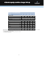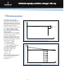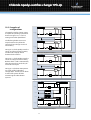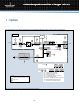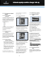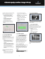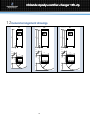
1
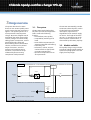
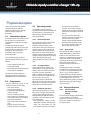
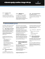
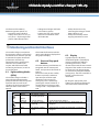
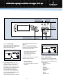
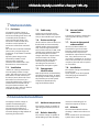
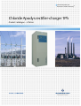
Industrial Power for
Business-Critical ContinuityTM
Chloride Apodys rectifier-charger 1Ph
Product catalogue — 2 Pulses
Chloride Apodys rectifier-charger
Rectifier — Battery charger
1-phase input — 2 Pulses - DC output
Scope
4
General requirements
4
Range overview
5
System description
6
Advanced Battery Care
7
Monitoring and Control Interfaces
8
Mechanical data
12
Environmental conditions
12
Technical data
13
Parallel operation
16
Options
18
General arrangement drawings
22
Chloride Apodys rectifierrectifier-charger 1Ph1Ph-2p
1 Scope
This document describes a
continuous duty single phase input,
stand-alone, Direct Current (DC)
output Uninterruptible Power
System (UPS).
The Apodys charger range meets
customers’ technical specifications
for industrial applications such as:
Power generation, Power
Transmission and distribution, Oil
and gas offshore developments
(platforms, FPSO, etc…), Oil and gas
transportation (pipelines…), Oil and
Gas treatment plants (refineries,
petrochemical units…), Railways
and undergrounds control and
signalling systems, etc...
The Apodys range is part of
Chloride’s know-how and long-time
relationship with industrial
businesses.
Chloride Industrial Systems services
include:
• Consultancy services
• Pre-engineering design and
support
• Project Management (contract
management, detailed
engineering, documents for
approval, manufacturing,
product testing, witness-testing
if requested, shipment, tailored
user manual)
• Services (recommended
commissioning spare parts,
commissioning services, product
lifetime spare parts, hotline,
trainings, maintenance
contracts, etc…)
2 General requirements
2.1. ISO certification
Chloride France S.A. is certified by
the British Standard Institution (BSl),
as a company with a total quality
and environmental control system
in accordance with the ISO 9001
and ISO 14001.
2.2. Applied standards
The Apodys range of battery
chargers shall have the CE mark in
accordance with the Safety and EMC
Directives 2006/95/EC and
2004/108/EC.
The Apodys charger range is
designed and manufactured in
accordance with the following
international standards:
• IEC60146 Semi conductor
converters:
− IEC60146-1-1 specifications of
basic requirements
− IEC60146-1-3 transformers
and reactors
− IEC60146-2 self-commutated
semiconductor converters
including direct dc converters.
• IEC60950 Safety of information
technology equipment including
electrical business equipment
• IEC60439 Low voltage
switchgear and control gear
assemblies
− IEC60439-1 Type-tested and
partially type-tested
assemblies
− IEC60439-2 Particular
requirements for busbar
trunking systems (busways)
− IEC 60439-3 Particular
requirements for LV
switchgear and control gear
assemblies intended to be
installed in places where
unskilled persons have access
4
•
•
•
•
for their use — distribution
boards
IEC60529 Degrees of protection
provided by enclosures (IP Code)
IEC60726 Dry-type power
transformers
EN61000-6-2 Electromagnetic
compatibility (EMC) Generic
standards — Immunity for
industrial environments
IEC61000-6-4 Electromagnetic
compatibility (EMC) Generic
standards — Emission standard
for industrial environments.
Chloride Apodys rectifierrectifier-charger 1Ph1Ph-2p
3 Range overview
The system described is a static
direct current uninterruptible power
supply system (DC UPS) as shown in
Figure 1. The system operates on a
microprocessor-based thyristors
charger. By means of digital control
technology the performance of the
rectifier / charger are enhanced. By
adding system components, such as
paralleling diodes, safety and
disconnecting devices, distribution
cubicles, isolated or non-isolated
DC/DC converters, as well as
software and communications
solutions, it is possible to set up
elaborated systems ensuring
complete DC load protection.
3.1. The system
The DC UPS provides high quality
DC power for electronic equipment
loads. It offers the following
features:
• Increased DC power quality
• Compatibility with all types of
loads
• Power blackout protection (for
systems associated with battery)
• Full battery care
• Lifetime of, at least, 20 years,
combined with an appropriate
preventive maintenance
• Operation temperature of 0 to
40°C permanent.
The DC UPS automatically provides
continuous electrical power, within
the defined limits and without
interruption, upon failure or
degradation of the network supply
AC source. The length of the backup time, i.e. autonomy time in the
event of power network failure, is
determined by the battery capacity.
3.2. Models available
The Apodys charger range includes
several DC voltage output models as
specified in paragraph 9. It is of the
single-phase input type.
Charger cubicle
DISPLAY
U, I, F
U
U, I
I
Charger
-Q01
-Q3
AC SUPPLY
1 Ph
DC LOAD
Battery protection
*
BATTERY
Legend:
*
Interconnection cables not supplied by Chloride
Figure 1: APODYS rectifier-charger single line diagram
5
-F5
Battery
fuse
Chloride Apodys rectifierrectifier-charger 1Ph1Ph-2p
4 System description
In this section, the main power
electronic features and the
operating modes of the Apodys
rectifier-charger range are
described.
4.1. General description
The single-phase current taken from
the AC source is converted to a
regulated DC voltage by a 2-pulse
rectifier.
In order to protect the power
components within the system, the
rectifier bridge is fused with a fast
acting fuse. A transformer is
provided at the input of the
rectifying bridge.
The rectifier/charger is able to
operate with the following types of
battery:
•
•
•
•
Valve regulated Lead Acid
Vented Lead Acid
Recombination Nickel Cadmium
Vented Nickel Cadmium
The selection of the optimum
charging method is completely
managed by the microprocessor.
4.2. Components
The DC UPS shall consist of the
following major components:
• One input isolator
• One main transformer
• Thyristors bridge Rectifier /
battery charger
• One LC smoothing circuit
• One Control unit, based on one
microprocessor and one Digital
Signal Processor-DSP
• One control and visualisation
unit
• Battery stand or matching
battery cubicles if requested
4.3. Operating modes
The Apodys rectifer-charger is
regulated with constant voltage and
current limiting, respecting an UI
characteristic. The DC UPS will
operate as follows:
4.3.1. Normal operation
The critical DC load is continuously
supplied by the rectifier. The
rectifier/ charger derives power
from the AC source and converts it
into DC power for the critical load
whilst simultaneously maintaining
the battery in a fully charged and
optimum operational condition. The
rectifier-charger operates in floating
mode, floating voltage being
determined by the battery type and
data.
4.3.2. AC supply failure
Upon fault of the AC source, the
critical load is still supplied by the
battery. The critical DC load draws
its power from the associated
battery without switching. During
failure, reduction or restoration of
the AC source, there is no
interruption to the critical load.
While the critical load is powered by
the batteries, indication is provided
of the battery discharing status.
4.3.3. Recharge operation
Upon restoration of the AC source,
the rectifier-charger automatically
restarts and gradually takes over
both the DC load and the battery
recharge, even if the batteries are
fully discharged.
This operational mode is a fully
automatic function and does not
cause any interruption to the
critical load. It operates as follow:
6
• For a power failure below 5
minutes, the rectifier-charger
automatically remains in floating
mode upon restoration of the AC
source.
• For a power failure beyond 5
minutes and upon restoration of
the AC source, the rectifiercharger automatically switches
to the equalizing charge mode
for 15 hours and then switches
back to the floating mode.
4.3.4. Boost mode
This operating mode is a specific
mode dedicated to vented type
batteries. It is used when boost
charge or commissioning charge is
requested. Before launching this
operating mode, the operator shall
check that all DC loads are
disconnected from the DC UPS
output.
During boost mode, the voltage
limitation is increased (up to 2.65V
per cell for a Lead Acid battery and
up to 1.7V per cell for a Nickel
Cadmium battery). Restoration of
the floating mode is automatic after
a preset typical time of 5 hours,
unless the floating mode is manually
initiated by the operator through
the control unit.
4.4. Electrical features
4.4.1. Total harmonic
distortion of input
voltage
The maximum voltage THD allowed
on the rectifier input is 8% to
guarantee the correct operation of
the system (either from utility or
from generator).
Chloride Apodys rectifierrectifier-charger 1Ph1Ph-2p
4.4.2. Rectifier current
limitation
4.4.3. Battery current
limitation
The rectifier-charger current is
limited to the nominal value either
in floating, charge and boost mode.
The battery current is limited to
0,1C (Pb) or 0,2C (NiCd) of the
associated battery, in floating or
charge modes. In equalization
mode, the battery current is limited
to 0,05C (Pb) or 0,1C (NiCd).
4.4.4. Over voltage protection
The rectifier-charger is
automatically turned off if the DC
voltage exceeds the maximum value
associated to their operational
status.
5 Advanced Battery Care
The Apodys range increases battery
life by using several battery care
features, as described hereafter.
5.1. Operating parameters
Unless specified in the customer’s
technical specification, the battery
parameters are determined by
Chloride Industrial Systems in full
respect with the customer’s
application and the choice of
battery type.
The battery parameters to be
determined and set up in the DC
UPS are:
• High voltage alarm (V)
• Float voltage (V)
• Charge voltage (V)
• Boost voltage (V)*
• End of discharge voltage (V)
• Battery discharging alarm (V)
• Minimum battery test
voltage (V)**
• Imminent shutdown alarm (V)
*according to battery type
**optional
5.2. Automatic battery
test
The operating conditions of the
batteries are automatically tested
by the control unit at selectable
intervals, e.g. weekly, fortnightly or
monthly. A short-time discharge of
the battery is made to confirm that
all the battery blocks and
connecting elements are in good
working order. In order to avoid a
faulty diagnosis, the test is launched
15 hours after the last battery
discharge at the earliest.
The battery test is performed
without any risk to the user, even if
the battery is wholly defective. A
detected battery fault is alarmed to
the user. The battery test does not
cause any degradation in terms of
expected life of the battery.
5.3. Ambient temperature
compensated battery
charger
The rectifier-charger output voltage
operates within narrow limits
according to the battery
manufacturer’s technical data. In
order to ensure an optimum battery
charging, regulation is
automatically adjusted to the
ambient temperature.
The float voltage and the discharge
voltage of the battery are
7
automatically adjusted as a function
of the temperature in the battery
compartment in order to maximise
battery operating life.
The temperature adjustments
are:
• -3 mV/°C/cell for Lead Acid
battery
• -2 mV/°C/cell for Nickel
Cadmium battery
•
5.4. Battery Monitoring
System (optional)
The Apodys range can be connected
to our Battery Monitoring System,
upon request (contact us for more
details).
The use of the Battery Monitoring
System significantly increases the
reliability and safety of batteries,
and thus the reliability of the entire
DC UPS unit.
Chloride Apodys rectifierrectifier-charger 1Ph1Ph-2p
• It diagnoses changes and faults
in the battery system
• It warns the user early enough
before the breakdown of the
whole DC UPS.
The features of the Battery
Monitoring System option are:
• It monitors each individual
battery block (of 6V or 12 V) or
cell (2V or 1.2V) throughout all
phases of DC UPS operation.
• It helps localise errors by
measuring the voltages of each
battery block or cell.
• It helps to drastically reduce
ongoing maintenance costs.
6 Monitoring and Control Interfaces
The rectifier-charger incorporates
the necessary controls, instruments
and indicators to allow the operator
to monitor the system status and
performance and take any
appropriate action. Furthermore,
interfaces are available upon
request, which allow extended
monitoring and control, as well as
service functions.
6.1. Light emitting diodes
(LEDs)
The rectifier-charger includes 3
external Light Emitting Diodes
(LEDs) to indicate the overall system
operation status as well as the
condition of the functional blocks.
LEDs operation is described in
Figure2.
Symbol
LED colour
Green
Green
flashing
Orange
Red
STOP
These LEDs shall interact with the
active mimic diagram displayed on
the graphical display.
6.2. Start and Stop push
buttons
The Start and Stop push buttons are
integrated into the mimic panel
board, and operate as described on
Figure3.
The control incorporates a safety
feature to prevent inadvertent
operation yet still allow rapid
shutdown in the event of an
emergency. This is achieved by
pressing the “STOP” button for 2
seconds before the charger stops.
« Charger OFF » is displayed on the
LCD.
Description
DC UPS or rectifier
normal operation
6.3. Display
A graphical (64 x 128 pixels)
illuminated Liquid Crystal Display
(LCD) is provided to enable the
operating parameters, all the
measurements and the active mimic
diagram of the rectifier or DC UPS to
be monitored. The LCD messages
are accessed by navigation buttons
(see Figure3). The text is available in
English, unless otherwise
mentioned.
By using the appropriate pushbuttons it is possible to display the
information described hereafter.
Comments
/
load on battery
DC UPS or rectifier
warning
Loads powered by battery
One or more subassembly are affected but not
stopped
DC UPS or rectifier
fault
Subassembly are faulty and stopped or manually
stopped
Figure 2: Apodys rectifier-charger — Light Emitting Diodes (LED) operation description
8
Chloride Apodys rectifierrectifier-charger 1Ph1Ph-2p
“System normal” LED
“Warning” LED
“Alarm” LED
STOP
C
Charger
“Inverter
ON/OFF”
Push button
OK
Navigation buttons:
Up and down (in menus)
Valid and Cancel (parameters)
“Charger ON/OFF”
Push button
Reset audible alarm
Push button
(Until a new alarm occurs)
Figure 3: Apodys rectifier-charger — Local human-machine interface.
6.3.1. Default page
The default page displays the active
mimic diagram of the rectifier or DC
UPS system (see Figure 4).
of the default page active mimic
diagram.
6.3.2. Active mimic diagram
The active mimic diagram displays
the following information:
• View of the connected load
• View of the power flow
• View of the status of each
functional block
The Figure 5 provides an example of
an active mimic situation:
Figure 4: mimic default page.
By pressing the “OK”, “UP”, or
“DOWN” buttons, the user enters
the general menu. If the user is
navigating in the menus, he may
return to the active mimic diagram
by pressing the “C” button.
If the user does not request any
action (such as pressing a button)
for 5 minutes while displaying the
menus, the system will
automatically return to the display
• Mains input failure
• Charger stopped
• DC load still supplied by battery
discharge
9
Figure 5: Example of Mimic situation
6.3.3. General menu
Pressing any key from the default
page (active mimic diagram) allows
the user to access to the following
general menu:
• Rectifier-charger
• Battery
• Reset
• Event log
• Display setting
• Date/Time
• Contact
• About
• Adjust param
Chloride Apodys rectifierrectifier-charger 1Ph1Ph-2p
6.3.4. Menus of functional
blocks
Each functional block (charger
block, battery block) includes its
own menu to provide the user with
detailed information, such as:
• Block status
• Block measures
• Block faults
• Block warnings
By using these menus, the user can
access to detailed information
about each following component:
• Rectifier-Charger
• Battery
• Load
6.3.5. Rectifier-charger
information
Status indications:
Charger off
Initialisation
Charger stop
Equalisation mode*
Equalisation imposed*
Floating mode
Battery test mode*
Battery test imposed*
Boost mode*
Measures indications:
UDC (charger output voltage)
IDC (charger output current)
U12 (Input voltage ph 1 and 2)
U23 (Input voltage ph 2 and 3)
U31 (Input voltage ph 3 and 1)
I1 (input line current)
I2 (input line current)
I3 (input line current)
Freq (input frequency)
Number of mains failures
Charger in current limit
Customised message 1*
Customised message 2*
Customised message 3*
Fault indications:
No fault
High DC voltage
High DC voltage memorised
Too high I battery memorised
Charger fuse blown
Input protection opened
Charger off
Remote switch off*
AC supply fault
Customised message 1*
Customised message 2*
Customised message 3*
* Optional messages (according to
specification and system configuration)
6.3.6. Battery information
Status indications:
Normal
Discharging
Charging
Fault or warning
Measures indications:
Battery voltage
Battery current
Battery temperature
Battery autonomy (%)
6.3.7. Event log
The Event Log function is available
through the display and allows
memorising each event into the
historical record, in a chronological
way.
The Event Log function can operate
in 2 different ways:
• Saturable mode: It records a
maximum of 100 events after
the first event appearance.
• FIFO mode: After recording 100
events, the 101st event deletes
the 1st one and so on.
6.3.8. Commissioning
adjustments
By using the menu “Adjust param”,
it becomes possible to the user to
define its own settings for the
charger commissioning. Up to 27
parameters can be user-defined
such as:
• Boost voltage adjustment
• Equalization voltage adjustment
• Battery current limitation setting
Imminent shutdown threshold
Warnings indications:
DC earth fault*
Battery begin discharge
Imminent shutdown
Temp sensor fault memorised*
Warning BMS*
Customised message 1*
Customised message 2*
Customised message 3*
Warning indications:
Test mode
Fan failure*
DC voltage low
Overload inhibit
Customised message 1*
Customised message 2*
Customised message 3*
* Optional messages (according to
specification and system configuration)
Faults indications:
Battery test fault memorised
End of discharge
Battery protection opened*
10
6.4. Remote signalling
and control signal
6.4.1. Logic outputs for remote
indications
The Apodys rectifier-charger is able
to deliver several output
information. Upon request, these
output information can be made
available on double-pole changeover (dpco) contacts (8A/250V AC1;
8A/30V DC1; 1A/60V DC1).
Chloride Apodys rectifierrectifier-charger 1Ph1Ph-2p
The following information can be
made available on voltage-free
contacts:
Charger OK
High DC voltage
Low DC voltage
Mains OK
Floating Mode
Equalization Mode
Initial charge mode
Battery test mode
When information is requested on
voltage-free contact, connection of
the customer cables is achieved on
the labelled, screw-clamp terminal
blocks of each relay-holder.
6.4.2. Logic inputs
The Apodys range allows the
signalisation of specific alarms from
the customer’s environment and
eventually takes the appropriate
action on the DC UPS thanks to
dedicated logic inputs available.
Upon request, the following logic
inputs can be wired:
Remote control on/off
Battery protection status
DC earth fault
Input protection status
Boost /commissioning mode
Shield
54
9 32
87 1
6
Figure 6: RS 232 SubD 9 points connector
Pin assignment is described in the
Table 1 hereafter.
Pin
1
2
3
4
5
6
7
8
9
Signal
Not used
Tx
Rx
Not used
RS232
GND
Not used
RTS
Not used
Not used
12
Explanation
34
5
Transmission RS232
Reception RS232
6
Signal ground
Figure 7: RS 485 6 points connector
Clear to send RS232
Table 1: RS232 pin assignment
NOTE:
If simultaneous use of RS232 port
and RS 485 is necessary, this will
require 2 separate PCB, one for
RS232 and the other for RS485.
6.5.2. Isolated RS 485 link
Upon request, Apodys can be
equipped with 6 points socket for
multipoint (1 master, up to 31
slaves, max 1300 meters) serial
RS485 communication.
The RS485 communication path
may be used either in 4 wires mode
or in 2 wires mode, as described in
the Table 2 hereafter.
Pin Signal
4-wires mode
1
GND
Not used
2
Tx-
3
Tx+
4
Rx-
5
Rx+
6
+5V
Transmission
RS485/ neg.
Transmission
RS485/ pos.
Reception
RS485/ neg.
Reception
RS485/ pos.
Not used
Table 2: RS 485 pin assignment
6.5. Communication
interfaces (options)
6.5.1. Isolated RS 232 link
Upon request, Apodys can be
equipped with one sub-D 9 points
connector for direct (1 master, 1
slave, max 15 meters) serial RS232
communication.
Customer connection is easily
achieved thanks to the screw-clamp
connector provided (see figure
below). Earth connection is
achieved on the PCB through a 6.35
Faston lug.
11
2-wires
mode
Not used
Negative
signal
Positive
signal
Not used
Not used
Not used
Chloride Apodys rectifierrectifier-charger 1Ph1Ph-2p
7 Mechanical data
7.1. Enclosure
The Apodys rectifier-charger is
housed in a space-saving modular
enclosure including front doors and
removable panels (standard
external protection IP 20). The
enclosure is made of sheet steel.
The doors can be locked. The
enclosure is of the floor mounted
type.
For harsh environmental conditions
(dust, water), a higher degree of
protection, of up to IP42 is available
in option.
Specific system design can be
achieved up to IP65. In such
extreme cases, technical
characteristics mentioned in this
document are not maintained.
7.2. Ventilation
Natural air cooling is standard on
most of Apodys rectifer-charger
range. The cooling air entry is in the
base and the air exit at the top of
the device (some device also need
side and/or rear clearance). It is
recommended that the enclosure is
installed with at least 400 mm of
free space between device and
ceiling at the top in order to allow an
unhindered cooling air exit.
7.3. Cable entry
Cable entry is achieved via the
bottom of the cabinet. Top cable
entry is also available upon request.
7.4. Enclosure design
All the surfaces of the enclosure are
finished with an electrostatically
applied powder-epoxy-polyester
coat, cured at high temperature.
Colour of the enclosure is RAL 7032
(pebble grey) textured semi-gloss.
For uniformity of the rectifiercharger with other equipments in
electrical rooms, the surface
finishing and the colour of the
enclosure may be available
according to the customer’s
specification and upon request.
7.5. Components
identification
Main components are identified by
self-adhesive vinyl labels. In option,
the Apodys rectifier-charger offers
the possibility to include specific
component identification by
engraved traffolyte labels.
7.6. Internal cables
connection
Connection of cables is achieved by
inserting cables directly in screwclamps.
7.7. Access to integrated
subassemblies
All internal subassemblies are
accessible for typical and most
frequent maintenance from the
front of the unit. Top access is
available for replacement of cooling
fans, if any. Rear access is not
required for installation or servicing.
In any case and if side or rear access
is required, the side and rear panels
are removable.
7.8. Installation
The rectifier-charger is forkliftable
from the front.
Upon request, it can be equipped
with lifting lugs to facilitate its
installation on site.
8 Environmental
Environmental conditions
The Apodys rectifier-charger is
capable of withstanding any
combination of the following
environmental conditions. It
operates without mechanical or
electrical damage or degradation of
operating characteristics.
8.1. Ambient temperature
level (non-condensing) for an
ambient temperature of 20°C.
The rectifier-charger is capable of
operating permanently from 0° to
40°C.
8.3. Altitude
8.2. Relative humidity
The rectifier-charger is capable of
withstanding up to 90% humidity
12
The maximum altitude without
derating is 1000 metres above sea
level.
Please consult us for operating the
system above 1000 metres.
Chloride Apodys rectifierrectifier-charger 1Ph1Ph-2p
9 Technical data
Data common to the complete Apodys 1Ph-2P rectifier-charger range
Rectifier input
Nominal input voltage
Input phases
Input voltage tolerance
Nominal frequency
Tolerance on frequency
Rectifier type
Isolation transformer
soft start
Maximum recommended voltage distortion (THD) from Mains (or generator)
on the input of the rectifier
(V)
(s)
230 [220 / 240] (other upon request)
1 ph
+10 / -10
50 / 60 (factory setting selectable)
+5 / -5
2-pulse (2 thyristors — 2 diodes)
Standard
5
(%)
8
(%)
(Hz)
(%)
Rectifier output
DC voltage stability
DC voltage ripple in float (with battery connected)
Rectifier-charger current limitation (in floating, charge or boost)
(%)
(% rms)
+/-1 (+/-1.5 for paralleled systems)
1
I nominal
System data
External protection degree
Internal protection degree
Cable entry
Access
System design life
(years)
IP 20
IP 20 open door
Bottom
Front
20 minimum
Environmental data
Operating temperature
Storage temperature
Maximum relative humidity (non condensing)
Operating altitude
(°C)
(°C)
(%)
0 to 40 (permanent operation)
0 to +70
<90
1000 m (without system derating)
Battery
Battery types
Lead Acid or Cadmium Nickel,
vented or recombination types
From 10 minutes to hours
Battery autonomy
Battery current limitation in floating and charge modes
According to customer’s specification
Typical values:
0.1C (Lead Acid battery)
0.2C (Nickel Cadmium battery)
0,05C (Lead acid battery)
0,1C (Nickel Cadmium battery)
Battery current limitation in boost mode
13
Chloride Apodys rectifierrectifier-charger 1Ph1Ph-2p
Data for 24 VDC output systems
Ratings
(A)
25
60
100
160
250
(A)
5.9
13.2
21.7
52.8
13.2
(V)
(V)
(A)
24
27.24
25
60
100
160
250
(W)
(%)
(dBA)
(mm)
(mm)
(mm)
(m²)
(kg)
N
264
72
60
1852
600
608
0.36
90
N
488
77
60
1852
600
608
0.36
114
N
768
78
60
1852
600
608
0.36
144
N
1158
79
60
1852
800
808
0.64
227
N
1702
80
60
1852
800
808
0.64
285
A0
A0
A0
B0
B0
Rectifier input
Current consumption at full load
Rectifier output
Battery nominal voltage
Output voltage in floating
Max DC current
System data
Heat dissipation system(*)
Dissipated power
Efficiency(***)
Noise
Height
Width
Depth
Footprint
Mass(**)
Drawing code (see paragraph 12)
Code for general arrangement
NOTA: These data are typical and are valid in the following conditions: Sealed lead acid battery (12 cells) operated at Ufloat=2,27V per cell and at 20°C, with a 1x230VAC
Mains input at cos phi=0,7. The system can also be designed and pre-set for use with any other type of stationary battery.
-(*) N: Natural cooling / F: Fan-assisted cooling
-(**) For information only. Mass may vary according to configurations and options
-(***) For tolerance, see IEC 60146-1-1
Data for 48 VDC output systems
Ratings
(A)
25
60
100
160
250
(A)
10.6
24.7
40.2
63.7
98.3
(V)
(V)
(A)
48
54.48
25
60
100
160
250
N
340
80
60
1852
600
608
0.36
117
N
717
82
60
1852
600
608
0.36
146
N
1037
84
60
1852
600
608
0.36
197
N
1538
85
60
1852
800
808
0.64
285
N
2217
86
60
1852
800
808
0.64
355
A0
A0
A0
B0
B0
Rectifier input
Current consumption at full load
Rectifier output
Battery nominal voltage
Output voltage in floating
Max DC current
System data
Heat dissipation system(*)
Dissipated power
Efficiency(***)
Noise
Height
Width
Depth
Footprint
Mass(**)
(W)
(%)
(dBA)
(mm)
(mm)
(mm)
(m²)
(kg)
Drawing code (see paragraph 12)
Code for general arrangement
NOTA: These data are typical and are valid in the following conditions: Sealed lead acid battery (24 cells) operated at Ufloat=2,27V per cell and at 20°C, with a 1x230VAC
Mains input at cos phi=0,7. The system can also be designed and pre-set for use with any other type of stationary battery.
-(*) N: Natural cooling / F: Fan-assisted cooling
-(**) For information only. Mass may vary according to configurations and options
-(***) For tolerance, see IEC 60146-1-1
14
Chloride Apodys rectifierrectifier-charger 1Ph1Ph-2p
Data for 110 VDC output systems
Ratings
(A)
25
60
100
160
250
(A)
22.1
51.7
84.3
133.3
205.9
(V)
(V)
(A)
110
118.04
25
60
100
160
250
N
604
83
60
1852
600
608
0.36
129
N
1250
85
60
1852
600
608
0.36
217
N
1764
87
60
1852
600
608
0.36
305
N
2575
88
60
1852
800
808
0.64
459
N
3647
89
60
1852
800
808
0.64
605
A0
A0
A0
B1
B1
Rectifier input
Current consumption at full load
Rectifier output
Battery nominal voltage
Output voltage in floating
Max DC current
System data
Heat dissipation system(*)
Dissipated power
Efficiency(***)
Noise
Height
Width
Depth
Footprint
Mass(**)
(W)
(%)
(dBA)
(mm)
(mm)
(mm)
(m²)
(kg)
Drawing code (see paragraph 12)
Code for general arrangement
NOTA: These data are typical and are valid in the following conditions: Sealed lead acid battery (52 cells) operated at Ufloat=2,27V per cell and at 20°C, with a 1x230VAC
Mains input at cos phi=0,7. The system can also be designed and pre-set for use with any other type of stationary battery.
-(*) N: Natural cooling / F: Fan-assisted cooling
-(**) For information only. Mass may vary according to configurations and options
-(***) For tolerance, see IEC 60146-1-1
15
Chloride Apodys rectifierrectifier-charger 1Ph1Ph-2p
10 Parallel operation
The Apodys rectifier-charger
systems have the capability to be
connected in parallel for dual or trial
configurations between units of the
same rating. The parallel connection
of Apodys rectifiers-chargers
increases reliability for the DC load.
U
U0
US = 0.5 %
10.1. Operating principle
The paralleling principle is based on
static regulation.
The characteristic U = f(I) is slightly
changed to give it a small slope (of
0.5 to 1%) - (see Figure 8).
The internal voltage reference U0 is
modified according to the current
the charger must supply, so that the
characteristic becomes:
US = U0 — kI
where:
US = output voltage
U0 = reference voltage
k = static regulation coefficient
I = charger output current
Thus, when 2 chargers are
connected in parallel, the
characteristics are:
US1 = U01 — k1I1
US2 = U02 — k2I2
And, US1 = US2
The U0, k and I parameters are set to
the same values so that output
currents are similar: I1 = I2
(see Figure 9)
I
Figure 8: Slope description for static regulation of paralleled chargers
U
U01
U02
U03
Us
I3
Figure 9: Curve principle of 3 chargers in parallel
16
I2
I1
I
Chloride Apodys rectifierrectifier-charger 1Ph1Ph-2p
10.2. Examples of
configurations
The Apodys rectifier-charger range
is capable of operating in parallel as
shown on Figures 10, 11 and 12,
among some other possibilities.
Charger 1 cabinet
Common output cabinet
DISPLAY
U, I, F
U, I
U
I
Charger 1
AC SUPPLY 1
1 Ph
BATTERY
DC LOAD
I
The blocking diodes ensure one
major function: They allow the
control of the recharge current of
each battery.
Charger 2 cabinet
DISPLAY
U, I, F
U, I
U
Charger 2
AC SUPPLY 2
1 Ph
On Figure 10, both Apodys rectifiers
concur to charge the same battery.
The DC load is equally shared
between both rectifiers.
Figure 10: Parallel configuration example 1
Charger 1 cabinet
Common output cabinet
DISPLAY
U, I, F
On Figure 11, both Apodys rectifiers
concur to charge the same battery.
Both DC loads 1 and 2 automatically
take the power they need, they do
not need to be equal.
U, I
U
I
Charger 1
AC SUPPLY 1
1 Ph
DC LOAD 1
BATTERY
I
On Figure 12, both DC UPS systems
are in full-parallel redundant
configuration. The DC bus tie allows
to take a full system off while
maintaining the 2 distribution
systems.
Charger 2 cabinet
DISPLAY
U, I, F
U, I
U
Charger 2
AC SUPPLY 2
1 Ph
DC LOAD 2
Figure 11: Parallel configuration example 2
Charger 1 cabinet
Distribution cabinet
APODYS
DISPLAY
U, I, F
U, I
U
Charger 1
AC SUPPLY 1
1 Ph
DC DISTRIBUTION 1
Battery protection box 1
I
BATTERY 1
Battery protection box 2
BATTERY 2
I
Charger 2 cabinet
APODYS
DISPLAY
U, I
U, I, F
U
Charger 2
AC SUPPLY 2
1 Ph
DC DISTRIBUTION 2
Figure 12: Parallel configuration example 3
17
Chloride Apodys rectifierrectifier-charger 1Ph1Ph-2p
11 Options
11.1. Main electrical options
The list of options described in this section is non-exhaustive. Please consult us for any other requirement.
Charger cubicle
DISPLAY
5
U, I, F
1
2
6
I
U
U, I
4
3
-V2
-Q3
AC SUPPLY
1 Ph
-K01
Dropping Diodes
Charger
-Q2
-K02
-Q41
-Q01
Special
Ripple filter
Two step start-up
contactor
Charger output
blocking diode
-A01
11
-K5
Switch
Shunt
trip
*
-Q00x
7
Earth
Leakage
Monitor
8
-Q5
Battery
protection
-Q5
Battery
protection
BATTERY
Low voltage
detection relay
Low voltage
disconnect
contactor
CIC
Battery protection box
*
9
10
Input or output protection option:
(for option 1 )
Battery protection option:
(for options 9 and 10 )
-F5
Fuse
Standard:
-Q3
switch
-Q5
Fuse switch
Option:
-Q3
circuit breaker
-Q5
Circuit breaker
-Q2 : CHARGER OUTPUT ISOLATOR
-Q3 : CHARGER INPUT PROTECTION
-Q5 : BATTERY PROTECTION
-Q41 : VOLTAGE REGULATOR INPUT SWITCH
-Q01 : DC LOAD MAIN ISOLATOR
-Q001 TO Q00X : DISTRIBUTION CIRCUIT BREAKERS
Legend:
Interconnection cables not supplied by Chloride
Optional part, available upon request
1
-Q001
DC LOAD
-K1
*
DC distribution
-K1 : TWO STEP START CONTACTOR
-K01 -K02: DROPPING DIODE CONTACTORS
-V2 : CHARGER OUTPUT BLOCKING DIODE
Option number
Figure 13: Apodys 1Ph-2P rectifier charger — overview of electrical options
18
Chloride Apodys rectifierrectifier-charger 1Ph1Ph-2p
Option Option
No.
name
Charger input
1
Function / description
Protect the input of the DC UPS system by a double-pole input circuit breaker.
protection
2
Two-step
start-up
contactor
3
Additional
ripple filter
4
Blocking
diode
5
Dropping
diodes
Chloride’s standard is a double-pole input switch on the input.
Limit the inrush current on starting up the system to 8 times the nominal input current (15 times as standard).
Addition of a two-steps start-up device to limit the inrush current due to the magnetisation of the transformer.
Please note that the rectifier dimensions mentioned in this document may not be maintained with this option.
Reduce the DC voltage ripple below the Chloride standard of 1% RMS.
2 filters configurations are made available to reach the following data:
− Telecommunication filter. CCITT curve.
− Current ripple 0.1C/10 rms, battery connected, for VRLA batteries.
Operate two or more rectifiers-chargers in parallel.
See paragraph 0 for further details.
Adapt the system output voltage to make it compatible with the DC connected loads.
Operating conditions and technical data of some batteries are often not compatible with the critical DC load
connected to the UPS output. This is particularly the case when operating the DC UPS with Nickel Cadmium
batteries, with which the gap between charge voltage and discharge voltage is wide. The dropping diodes
option allows answering to these operating conditions.
The dropping diodes are successively shunted in order to respect the DC voltage accepted by the load. One or
more voltmetric relays measure the battery voltage and control the contactors to smoothly drop the output
voltage.
6
DC
distribution
7
Low voltage
disconnect
contactor
(LDV)
Earth leakage
monitor
(DC earth fault
alarm)
8
9
Battery
protection
This option may affect the overall dimensions of the system.
Ensure the distribution, protection and segregation of the DC load.
Distribution boards may be included in the UPS system or installed in a separate cabinet. These distribution
boards may be customised according to the customer’s requirements. MCB, MCCB, or fuses are available.
Protect the battery from deep discharges and thus enhance battery lifetime.
The LDV option includes an output contactor controlled by voltage relay in order to disconnect the load at the
end of battery autonomy period. Reconnection of the load is automatic at the charger restoration and upon the
resumption of normal conditions.
Monitor the insulation resistance on the DC bus.
Used in conjunction with the isolation transformer, this option is made of an electronic circuit “Chloride CIC” (or
equivalent). It is fitted into the rectifier/charger cubicle and delivers remote indication by a changeover voltagefree contact. Local indication (inside the cabinet) by two LED’s is available on the PCB (or moulded device) to
indicate the polarity on fault. A local test push-button is also available on the device to simulate fault conditions
(+ or -).
Prevent any short-circuit that could occur on the battery circuit and therefore prevent the battery cables from fire
risks.
3 types of protections are made available:
− Fuse: fully rated fuse with auxiliary contact for the monitoring of its operating status.
− Fuse switch: fully rated fuse switch with auxiliary contact for the monitoring of its operating status.
− Circuit breaker: fully rated circuit breaker and an additional auxiliary contact for the monitoring of its position.
10
External
battery
protection
11
Charger
output switch
Protect the battery circuit as for option 9.
The battery protection device is housed in a wall-mounted metal box for battery systems mounted on racks and
it is supplied with the battery cabinet, when the battery is fitted in a matching cubicle. Furthermore, this device
serves as a safety element for the cross section of the power cable between the UPS and the remotely placed
battery system. Therefore, the wall-mounted box must be installed as close as possible to the battery and the
length of cables between battery and UPS system must be the shortest.
Isolate the charger output.
The adjunction of this switch allows safe maintenance of the charger module. By opening the charger input
circuit and the charger output circuit, it becomes possible to safely maintain the charger module.
19
Chloride Apodys rectifierrectifier-charger 1Ph1Ph-2p
11.2. Environment-related
options
service conditions, as specified in
IEC 60146-2, §5.
11.2.1. External cubicle
protection
11.2.4. Anti-condensation
heater
According to IEC 60529 (Degrees of
protection provided by enclosuresIP Code), it is possible to protect the
rectifier/charger cubicle from solid
or liquid intrusion. The protection
levels available are:
• IP 21
• IP 22
• IP 40
• IP 41
• IP 42
In all cases, even for standard IP 20
level, the third number shall be 7,
representing mechanical
protection.
11.2.2. Special enclosure
finishing
This option includes a heater which
is fitted inside the cubicle, to
prevent internal components from
condensation, mainly when the UPS
is stored for a long period.
11.2.5. Temperature monitoring
Standard finishing of the enclosure
is RAL 7032 (grey) textured semi
gloss. Any other type of painting
specification is also achievable upon
request, in compliance with AFNOR,
RAL or BS standards.
11.2.3. Specific ambient
operation conditions
• Specific temperature conditions:
Upon request, the Apodys
charger is able to operate above
40°C (and up to 55°C) or below
0°C.
• Special seismic design: Specific
modifications of the system may
be added to allow the UPS to
operate in seismic risks areas.
Please consult us.
In such extreme conditions, the
customer must specify the required
This option consists in a thermostat
fitted inside the cubicle to indicate
abnormal heating in the UPS. This
device is adjustable below 90°C and
includes a remote indication
available on a normally open,
voltage-free contact.
11.2.6. EEx battery protection
box
Eex-classified battery protection box
is available when battery and DC
UPS systems operate in an area
where there is a risk of explosion.
This box includes the external
battery protection option.
20
11.3. Monitoring options
11.3.1. Customer interface
relays
It is possible to increase the number
of outputs described in paragraph 6
by providing additional output
relays. These outputs can be used to
monitor several parameters
specified by the user.
11.3.2. Modbus / Jbus
Upon request, Apodys charger is
able to remotely deliver information
through Modbus/Jbus protocol (2 or
4 wires).
This additional feature includes:
A hardware kit: an additional
communication board is included
into the Apodys charger. Customer
connections are described in
paragraph 6.
A software kit: The Apodys charger
is delivered with Chloride’s standard
Modbus/Jbus code (embedded into
the system) and fully detailed
protocol coding documentation.
NOTE:
The communication cable between
the UPS and the monitoring station is
not part of Chloride’s supply.
11.3.3. Monitoring software
PPVis
Software solution is available to
remotely monitor all Chloride’s UPS
from the Apodys range (DC and AC
systems).
Chloride Apodys rectifierrectifier-charger 1Ph1Ph-2p
The PPVis software (windows based)
offers several features, such as:
• Current state of components
• Display of output voltage,
rectifier performances, load
current
• Number of power failures
• Available back-up time
• Data storage function
The figure hereafter shows a
PPVis screenshot for a DC UPS
system.
• On-time fault recognition,
enhancing the reliability of the
system
• Easy detection of the defective
battery block, reducing
correction and maintenance
costs
• Compatible with Nickel
Cadmium and Lead acid
batteries.
11.4.3. Internal lighting
Internal lighting is available upon
request to improve internal visibility
of the system.
11.4.4. Battery cubicle
Figure 15: Battery Monitoring System
screenshot
Matching battery cubicles are
available to provide a fully-enclosed
DC UPS system. The battery cubicle
includes the following:
• Cubicle
• Disconnecting means
• Fuses
• Power terminal blocks
11.4.5. Lifting eyes
Figure 14: PPVis software screenshot.
11.4. Other options
11.3.4. Battery Monitoring
The asociated battery can be
connected to the battery
management system from Chloride.
This system provides the following
features:
• Voltage measurement of each
battery block by mean of
separate battery measuring
modules.
• Analysis of each battery block
with measuring of the minimum
and maximum voltage values.
• Graphic visualisation and
analysis by means of dedicated
software
This system brings the following
benefits:
• Early detection of faults in the
battery circuit, increasing the
safety of the DC UPS system
11.4.1. Special identification of
internal components
As standard, the Apodys charger
includes internal sub-assemblies
identification with self-adhesive
vinyl labels. As an option, it is
possible to change these labels to
engraved traffolyte labels, black
signs on white background.
11.4.2. Top cable entry
The option allows power cable entry
from the top of the DC-UPS, by
adding an external cabinet to drive
the cables down to the bottom of
the UPS.
NOTE
This option may affect the overall
dimensions of the system.
21
Upon request, the rectifier-charger
cubicle can be equipped with lifting
eyes to facilitate its installation on
site.
Chloride Apodys rectifierrectifier-charger 1Ph1Ph-2p
12 General arrangement drawings
B0
IP 21, 22, 41, 42
1982
1852
100
100
100
1982
1982
IP 20, 40
0 mini
0 mini
WALL
0 mini
B1
IP 21, 22, 41, 42
IP 20, 40
1852
A0
WALL
800
800
WALL
IP 21, 22, 41, 42
700 x 45
282x120
282x120
282x120
800
800
600
382x120
22
808
808
608
0 mini
0 mini
200 mini
600
282x120
Chloride Apodys rectifierrectifier-charger 1Ph1Ph-2p
Notes
23
Chloride Apodys rectifierrectifier-charger 1Ph1Ph-2p
Emerson Network Power, a business of Emerson (NYSE:EMR), protects
and optimizes critical infrastructure for data centers, communications
networks, healthcare and industrial facilities. The company provides
new-to-the-world solutions, as well as established expertise and smart
innovation in areas including AC and DC power and renewable energy,
precision cooling systems, infrastructure management, embedded
computing and power, integrated racks and enclosures, power
switching and controls, and connectivity. Our solutions are supported
globally by local Emerson Network Power service technicians. Learn
more about Emerson Network Power products and services at
www.EmersonNetworkPower.com.
Locations
Europe, Middle East, Africa
Emerson Network Power
30 avenue Montgolfier — BP90
69684 Chassieu Cedex
France
Tel: +33 (0)4 78 40 13 56
[email protected]
North America
Emerson Network Power
2821 West 11th Street
Houston, TX 77008
USA
Tel: +1 800 442 7489 / +1 713 880 0909
[email protected]
Asia Pacific
Emerson Network Power
151 Lorong Chuan, lobby D
New Tech Park 556741
Singapore
Tel: +65 6467 2211
[email protected]
This publication is issued to provide outline information only and is not deemed
to form part of any offer and/or contract. The company has a policy of continuous
product development and improvement, and we therefore reserve the right to
vary any information without prior notice.
CH APODYS 2P-CATALOGUE-UK-Rev3-01-2012
Caribbean & Latin
Latin America
Emerson Network Power
1300 Concord Terrace, Suite 400
Sunrise, Florida 33323
Tel: +1 954 984 3452
[email protected]
Australia
Emerson Network Power
Suite A Level 6, 15 Talavera Road
North Ryde, NSW 2113
Australia
Tel: +61 2 9914 2900
[email protected]
Emerson Network Power
The global leader in enabling Business-Critical Continuity™.
EmersonNetworkPower.com
AC Power
Embedded Computing
Infrastructure Management & Monitoring
Precision Cooling
Connectivity
Embedded Power
Outside Plant
Racks & Integrated Cabinets
DC Power
Industrial Power
Power Switching & Controls
Services
24
Emerson, Business-Critical Continuity and Emerson Network Power are trademarks of Emerson Electric Co. or one of its affiliated companies. ©2012 Emerson Electric Co.