1
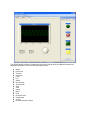
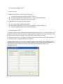
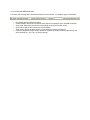
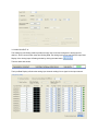
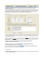
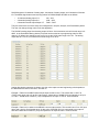
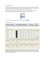
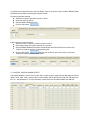
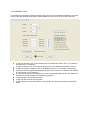
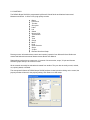
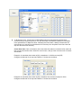
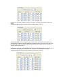
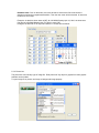
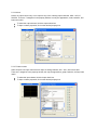
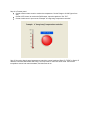
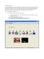
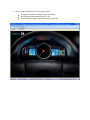
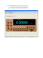
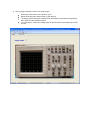
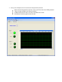
ReDAQ Shape SLX300 User Manual
isoLynx™ ReDAQ Shape SLX300 User Manual
isoLynx™ ReDAQ Shape SLX300 User Manual
MA1032 Rev. A—January 2010
The information in this manual has been checked carefully and is believed to be accurate; however,
Dataforth assumes no responsibility for possible inaccuracies or omissions. Specifications are subject to
change without notice.
© 2010 Dataforth Corporation. All rights reserved.
isoLynx is a trademark of Dataforth Corporation.
IBM, IBM PC, XT, AT, and PS/2 are trademarks or registered trademarks of
International Business Machine Corporation.
Microsoft, MS-DOS, Windows, Windows NT, Visual Studio, Visual C++, and Visual BASIC are
Trademarks or registered trademarks of Microsoft Corporation.
Trademarks or registered trademarks of National Instruments Corporation
TABLE OF CONTENTS
1. INTRODUCTION
1.1.
1.2.
1.3.
1.4.
1.5.
1.6.
OVERVIEW
DEVELOPER AND USER VERSION
INSTALLATION REQUIREMENTS
INSTALLATION
LICENSE UNLOCK KEY
RELATED DOCUMENTS
2. ReDAQ Shape INTEGRATED DEVELOPMENT ENVIRONMENT
2.1.
2.2.
2.3.
2.4.
2.5.
START WINDOW
PULL DOWN MENU
TOOL BAR
PANEL-SELECT WINDOWS
STATUS AND MESSAGE BAR
3. SETUP, CONFIGURE, AND ACQUIRE DATA IN ACQUIRE PANEL
3.1.
3.2.
3.3.
3.4.
3.5.
3.6.
3.7.
3.8.
ACQUIRE PANEL
COMMUNICATION
ANALOG INPUT [AI]
ANALOG OUTPUT [AO]
SCALE DATA
DISCRETE [DIO]
CONTROL LOOP AND ALARM OUTPUT
SD MEMORY CARD
4. TEST, PROCESS, AND ANALYZE DATA IN ANALYZE PANEL
4.1.
4.2.
4.3.
4.4.
4.5.
ANALYZE PANEL
VIEW RAW DATA
VIEW ANALOG INPUT CHANNELS
VIEW DISCRETE DIO CHANNELS
READ AND WRITE MODBUS REGISTERS
5. CREATE USER INTERFACE AND EDIT CONTROLS IN PRESENT PANEL
5.1.
5.2.
5.3.
5.3.1.
5.3.2.
5.3.3.
5.3.4.
5.3.5.
5.3.6.
5.3.7.
5.3.8.
5.3.9.
5.3.10.
5.3.11.
5.3.12.
5.3.13.
5.3.14.
PRESENT PANEL
TOOLBOX AND HOW TO CREATE A CONTROL
CONTROLS
Button
Picture box
Text box
Group box
Label
LED
Switch
Numeric edit
Thermometer
Slide
Tank
Gauge
Meter
Knob
5.3.15.
5.3.16.
5.3.17.
5.3.18.
Chart recorder
Scope
XY plot
Discrete waveform graph
6. QUICK START EXAMPLES
6.1.
6.2.
CLOSED LOOP CONTROL
DEMO PROJECTS
About Dataforth Corporation
―Our passion at Dataforth Corporation is designing, manufacturing, and marketing the best possible signal
conditioning and data communication products. Our mission is setting new standards of product quality,
performance, and customer service.‖ Dataforth Corporation, with over 20 years experience, is the
worldwide leader in Instrument Class™ Industrial Electronics—rugged, high performance signal
conditioning and data communication products that play a vital role in maintaining the integrity of
industrial automation, data acquisition, and quality assurance systems. Our products directly connect to
most industrial sensors and protect valuable measurement and control signals and equipment from the
dangerous and degrading effects of noise, transient power surges, internal ground loops, and other
hazards present in industrial environments.
Dataforth spans the globe with over 50 International Distributors and US Representative Companies.
Our customers benefit from a team of over 130 sales people highly trained in the application of precision
products for industrial markets. In addition, we have a team of application engineers in our Tucson factory
ready to address and solve any in-depth application questions. Upon receipt of a quote or order, our
Customer Service Department provides fast one-day response of delivery information. We maintain an
ample inventory that allows small quantity orders to be shipped from stock.
Errata Sheets
Refer to the Technical Support area of Dataforth‘s web site (www,dataforth.com) for any errata
information on this product.
1. INTRODUCTION
1.1. OVERVIEW
ReDAQ Shape is Dataforth‘s out-of-the-box data acquisition software for SLX200, SLX300 and MAQ20.
Users can use a built-in function (e.g. scope, I/O special function and data view spreadsheet) in the
Acquire and Analyze panels without setup and configuration. In addition, it takes only three easy steps
to create Presentation panels for application projects with 18 high quality controls and powerful functions
like automatic control loops and timers (count-down timer, 24 hour-day timer and date/time timer), etc.
For easy set up without detailed setup and configuration:
Select the Modbus options from the Acquire panel.
Click on the [RUN] button
, then view and process the data on the Acquire and
Analyze panel. The status bar at the bottom of the screen provides indications of current
activities. It includes Edit Lock, Modbus, Scan Mode, Scan Activity and Control Loop/Alarm
Output.
To create Presentation panels for application projects:
Select Acquire panel for quick setup and configuration of the system as well as testing and
acquisition of data.
Select Analyze panel to allow data logging, real-time analysis, and data processing.
Select Present panel that has the ability to build and create custom graphical user interfaces.
After selecting a Present panel, select controls such as Switch, Scope, LED, etc. Use
to see the control tool box, select the tool desired, and then click in the presentation
window. Double click on a control in the presentation window to open the control’s
property window. Change properties as desired and click the start button to run. See
Section 5 for details.
The following illustrates a presentation panel application project:
The ReDAQ Shape SLX300 is programmed by Microsoft‘ Visual Studio and National Instruments‘
Measurement Studio. It offers 18 very high quality controls:
Button
Picture box
Text box
Group box
Label
Led
Switch
Numeric Edit
Thermometer
Slide
Tank
Gauge
Meter
Knob
Chart Recorder
Oscilloscope
XY plot
Discrete Waveform Graph
All the controls are easily selected to create, move, resize, cut, copy, paste, and delete. Double click on
the selection to set its properties. These controls can also support any format of graphical files, so users
may use any graphical software to create a graphical presentation and load it into ReDAQ Shape.
The ReDAQ Shape SLX300 offers the best and easiest way to save, open, and create graphical user
interface projects, as well as to test, process, and analyze acquired data. It can log data to the hard drive,
and copy, and delete data at run time.
The ReDAQ Shape SLX300 also offers convenient way to setup and configure all of SLX300‗s functions:
•
•
•
•
•
•
•
Continuous and buffer scan modes for the 12 analog input channels and the 4 analog output
channels.[Acquire Panel -> Analog Input AI, Analog Output AO]
Automatically scale data from count to engineering units. [Acquire Panel -> Scale Data]
8 discrete I/O and special functions: Pulse/frequency counter, Counter with de-bounces,
Waveform measurement, Time between events, Frequency generator, PWM generator, and
One-shot pulses. [Acquire Panel -> Discrete Input-Output DIO]
Customer user tag name for any input and output. [Acquire Panel -> Analog Input AI, Analog
Output AO]
Cold junction compensation for J, K, R, S, and T, 8B thermocouple modules. [Acquire Panel ->
Analog Input AI]
Control loop and alarm output. It can easily setup output activities. [Acquire Panel -> Control
Loop / Alarm Output]
Timer (count-down timer, 24 hour-day timer and date/time timer) with 10 events.[Present panel ->
Toolbox -> Other Controls -> Button]
1.2. DEVELOPER AND USER VERSION
There are two versions (Developer and user version) of ReDAQ Shape in the CD. The Developer version
is a version that is fully functional with the capacity of creating a project, editing the controls and setting
up the parameters of SLX300. The user version can only run the finished project and it is for distribution
only.
Both versions of ReDAQ Shape can be installed on the same computer.
After the project is completed, save it as a user project only and then distribute the user project and the
user version of ReDAQ Shape.
The ReDAQ Shape SLX300 project file has two parts.
.
A project file with extension of sl3 (Developer version) or su3 (user version). Example,
project1.sl3 or project1.su3.
A folder includes all the image and text files of the project. The folder name is project name +
Images (Developer version) or project name + ImagesUser (user version).
Example: project1Iamges or project1IamgesUser.
1.3. INSTALLATION REQUIREMENTS
Before installing ReDAQ Shape SLX300, a computer must have the following:
Microsoft Windows 2000/XP/Vista/Win7.
Intel Pentium II class processor, 700MHz or higher.
Video display – 800x600, 256 color (16-bit color recommended for user interface controls) or
higher.
Minimum of 256MB of RAM (512MB or higher recommended).
Minimum of 405MB of free hard disk space.
Microsoft-compatible mouse.
1.4. INSTALLATION
To install ReDAQ Shape, complete the following steps:
Insert the ReDAQ Shape SLX300 CD into the CD drive.
Run setup.exe from the CD (select Developer version, user version or both).
Follow the installation instruction of the setup program.
To install USB driver, complete the following steps:
No need to connect the SLX300 hardware.
Run CP210x_VCP_Win_XP_S2K3_Vista_7 USB driver in ReDAQ Shape CD.
Follow the installation instructions of the setup program.
1.5. LICENSE UNLOCK KEY
The ReDAQ Shape software ships with SLX300 hardware when purchased. It is a fully functional copy of
software but can only run 30 min. It can be used for evaluation, testing and even real development. Order
the license unlock key from Dataforth, Corporation when purchase decision is made.
To install the license unlock code and serial number: open the Enter License Unlock Code window from
the help menu, type or copy/paste the license unlock key.
To install the license unlock code and serial number to Shape default setting: open the default project
[ReDAQ_default.sl3 (developer version) or ReDAQ_default.su3 (user version)] in ReDAQ Shape root file
folder. Input the license unlock key and save back to the default file (ReDAQ_default.sl3 or
ReDAQ_default.su3).
1.6. RELATED DOCUMENTS
The following documents are available from Dataforth Corporation:
•
•
•
•
isoLynx SLX300 Quick Start Guide
isoLynx SLX300 Software User Manual
isoLynx SLX300 Hardware User Manual
ReDAQ Shape SLX300 User Manual
The following documents are available from Modbus IDA ( www.modbus.org):
HU
•
•
•
UH
Modbus Application Protocol Specification
Modbus over Serial Line Specification & Implementation Guide
Modbus Messaging on TCP/IP Implementation Guide
The following Tools and documents are available from FieldTalk (www.modbusdriver.com):
HU
•
•
UH
Modbus Protocol Drivers and DLL Libraries
FieldTalk User Manual
The following Tools and documents are available from National Instruments ( www.ni.com):
HU
•
•
•
Free Modbus Protocol Drivers VI‘s and Examples
LabVIEW User Manual
Measurement Studio User Manual
UH
2. ReDAQ Shape INTEGRATED DEVELOPMENT ENVIRONMENT
2.1. START WINDOW
After starting ReDAQ Shape, the setting dialog box will be displayed for selecting settings, configurations
of development environment and parameters. The user can select the previous project settings [OK] or
the SLX300 system default settings [Cancel].
The following illustrates the Interactive Development Environment (IDE) of Shape. This IDE provides a
user friendly and comprehensive integrated development environment with easy to use pull down menus,
convenient toolbars, and three development windows [Acquire-Analyze-Present], which provide
convenient way to setup and configure SLX300. It can process, analyze, and acquire data, as well as
create and develop the users own interface, presentation projects, and automatic control loops.
2.2. PULL DOWN MENU
The pull down menu has 5 items:
File:
•
•
•
•
•
Open new project (Start a new project and reset Acquire, Analyze and Presentation panels to
default settings).
Open existing project.
Save project (Save the project to a file *.sl3. Each project also including image files and text files
on a separate folder *Images).
Save project for user only (Save the project to a user file *.su3. Each project also including
image files and text files on a separate folder *ImagesUser).
Exit (close ReDAQ Shape SLX300).
Edit:
•
•
•
•
•
Cut Control (Delete the selected control and send it to the clipboard).
Copy Control (Copy a selected control and send it to the clipboard).
Paste Control (Paste a control to a Presentation panel).
Delete control (Delete a control from a Presentation panel).
Edit lock/unlock (Select lock or unlock editing functions).
View:
•
•
•
•
Present panel (Add or remove a presentation panel).
Acquire panel (Show or hide the Acquire panel).
Analyze panel (Show or hide the Analyze panel).
Toolbox (Open or close the controls toolbox).
Run:
•
•
•
Start (Setup all the parameters of the SLX300 from the Acquire panel and run).
Pause (Keeps the parameter settings and pauses run. Click again to continue run).
Stop (Stop and reset all parameters).
Help:
•
•
•
ReDAQ Shape SLX300 User Manual.
Enter License Unlock Code.
About (About ReDAQ Shape).
2.3. TOOL BAR
There are 12 convenient tools on the tool bar:
They are [Open new project], [Open existing project], [Save project], [Cut], [Copy], [Paste], [Delete], [Edit
lock/unlock], [Toolbox open/close], [Start], [Pause] and [Stop].
2.4. PANEL-SELECT WINDOWS
There is one Acquire panel, one Analyze panel, and up to 20 Presentation panels.
The Acquire and Analyze panels can hide and show by using the view pull down menu.
The Presentation panels can be added, removed or renamed.
2.5. STATUS AND MESSAGE BAR
The status and message bar is located at the bottom of the window. It includes 6 types of information.
•
•
•
•
•
•
Edit: Shows the edit lock/unlock status.
Communication: Shows the connection status and error messages on the SLX300 connection.
Scan mode: Shows the current scan mode setting (continuous or buffer mode).
Scan interval: Shows the current scan interval setting.
Scan activity: Shows the start, pause, or stop activity by using a progress bar.
Controls Loop/Alarm Output activity: Shows the control loop output or alarm output activity and
active channel A0 – A11, N0 = no active channel.
3. SETUP, CONFIGURE AND ACQUIRE DATA IN ACQUIRE PANEL
3.1. ACQUIRE PANEL
The Acquire panel provides 7 select items for setup, configuration, and acquisition of data. They are
Modbus, Analog Input AI, Analog Output AO, Scale Data, Discrete DIO, Control Loop or Alarm Output
and SD Memory Card.
Before starting to run Shape, the Acquire panel must be setup. After setup, the Acquire panel can be
hidden using the view pull down menu as follows.
3.2. COMMUNICATION
The Communication setting window has the only settings that must be entered before running Shape.
Communication setting has the following parameters:
Slave ID: 16-31. Default = 16. Match the slave ID with the current SLX300 board.
TCP/IP and Serial Port select. Default = Serial (USB) Port. If TCP/IP is selected, the IP Address
has to be set. If serial port is selected, COM port name, baud rate, and parity have to be
selected.
IP Address. Default = 192.168.128.100
Serial port name: COM1-COM20. Default = COM3.
Serial port baud rates: 921600, 460800, 230400, 115200, 57600, 38400, 19200, 9600, 4800,
2400 and 1200. Default = 115200.
Parity: EVEN, NONE, and ODD. Default = EVEN.
To search for new available serial (USB) port, click the Search button.
To connect to the selected communication port of SLX300, click the Connect button or click the
Run button.
To reconfigure the communication setting of SLX300 system, Select the parameter of baud rate,
parity, RS485 and IP address then click Save New Setting button. The new communication
setting will take effect after cycle power on the board. To go back to the SLX300 default
communication setting, using the reset jump on the SLX300 board.
To close the selected port, click the Close button or close the Shape.
3.3. ANALOG INPUT AI
The Analog Input AI Setting window provides an easy way to test and configure the analog input AI
channel. After Communication setup and Scaling Data, the analog input can be read from the Input Data
Display of the Analog Input AI Setting window by clicking the start button.
Then the status bar shows:
The Input Data Display will show the analog input channel reading from a signal on the input channel.
The scan mode select window allows the choice continuous scan or buffer scan mode and scan
interval. Buffer scan mode, also allow the selection the buffer size in samples. In general,
continuous scan mode can continuously scan all 12 analog channels‘ data, but at lower speed.
The buffer scan mode stores data in the scan buffer, and retrieves data at the same time to
provide a fast sample rate. For more information, please check the Software User Manual.
To change the user tag name for each channel, input the text into the user tag name text box of
the channel.
To select the data for current, average, maximum and minimum of each channel, click on the
select data control box.
To input the average weight, input it to the average weight input box. The default setting is 4.
To reset the maximum and minimum value, click on the reset button of the channel.
To setup the cold junction compensation for a thermocouple input module, select the module
name from the cold junction compensation selection box and select the C or F for degree Celsius
or degree Fahrenheit. Shape automatically does the setup.
To use the control loop output or alarm output function for the analog input channel, select the
function from the control output or alarm selection box. Select tracking or latched mode for high,
low, high-low, high-high, low-low, and High-High Low-Low limit. Each may be either tracking or
latched control loop output or alarm. User also needs to set the output limit parameter on Control
Loop / Alarm Output tab.
To reset the alarm [latched mode and on alarm go to panel], click on the Reset Alarm button or
use the button control in the user‘s application project.
To enable or disable the on alarm go to alarm present panel function, click on the Enabled /
Disabled on alarm go to present panel select box.
For more control loop or alarm information, please check the SLX300 Software User Manual.
3.4. ANALOG OUTPUT AO
The Analog Output AO, Setting window provides an easy way to test and configure the analog output
channel. After communication setup and Scaling Data, click the start button.
The status bar shows:
Type in the data to Output Data box, the data will be output to the analog output channel in the
Continuous scan mode
The Default Output Data are user defined values which are the known safe output values in case of loss
of communication from the host or accidental power cycling of the SLX300. When SLX300 is powered on
or Shape stops, the default output takes effect. To set the default output first input the value into the
Default Output Data box and then clicks on the [Save Default to Hardware] button.
To configure the buffer mode of an AO, first stop Shape. Select buffer scan mode and set the interval in
ms. Next, program the output data for each of the AO‘s by typing into the Buffer Mode Output Data text
box, or open from a text file.
A comma separates each data point. At the end, if the value is less than minimum range, the output scan
will stop. If the value is larger than maximum range, the output scan will loop back to the starting point
and continue run.
U
U
U
U
Example 1: [AO range is 0 to 5], data = [0,1,2,3,4,5,6]
This example outputs a step up waveform.
or [0,1,2,3,4,5,7]
Example 2: [AO range is 0 to 5], data = [5,4,3,2,1,0,-1]
This example outputs a step down, one shot waveform.
or [5,4,3,2,1,0,-2]
Click on the start button to run after the setup.
To save or open the programmed output
data, click on the [Save To File] or [Open From File] button.
3.5. SCALE DATA
The Scale Data setting window provides an easy way for the user to scale the analog input, AI channels,
and analog output, AO channels.
SLX300 supports 12 channels of analog input, 4 channels of analog output, and 8 channels of discrete
I/O. The default signal names and user tag names for ReDAQ Shape SLX300 are as follows:
•
•
•
12 channels Analog Input 0-11:
4 channels Analog Output 0-4:
8 channels Discrete Input-Output 0-7:
AI0 – AI11.
AO0 – AO3.
DIO0 – DIO7.
They are used for the rest of the setup and configuration in Acquire, Analyze, and Presentation panels.
The user can change the tag name to suit the application.
The SLX300‘s analog input AI and analog output AO have 12-bit resolution so that full scale range is 04095. In the Scale Data Setting window, full scale can be scaled to any engineering scale for each
channel. By default, the analog input is 0 to 5V so set the AI full scale range to 0 to 5V. The analog
output also is 0 V to 5V, so set the AO full scale range to 0V to 5V.
Analog data always represents a voltage. How this value maps to actual engineering units depends on
the 8B module the data is read from, or written to.
Example 1: Data from an 8B37J thermocouple input module is read. This module has a -100°C to
+760°C input range and a 0V to +5V output range. A data value of 0x0000 (0V) corresponds to an input
of -100°C. A data value of 0x0FFF (+5V) corresponds to an input of +760°C. Enter as below:
Example 2: Data is to be written to an 8B39-01 current output module. This module has a 0V to +5V input
range and a 4mA to 20mA output range. A data value of 0x0000 (0V) is to correspond to an output of
4mA and a data value of 0x0FFF (+5V) corresponds to an output of 20mA. Enter as follows:
3.6. DISCRETE DIO
The Discrete DIO Setting window provides an easy way to test and configure the Discrete I/O channels
and I/O special functions of Pulse/frequency counter, Counter with de-bounce waveform measurement,
Time-between events, Frequency generator, PWM generation and One-shot pulse.
To use the discrete I/O, first select the DIO states [Vacant, Input, Output, and Alarm]. The default is
Vacant. The state of alarm is automatically set by Control Loop / Alarm Output setting.
Then, select the DIO interval in ms, and click the start button.
The status bar shows:
Now, the user can read DIO data from the [Input Data Display] and write to DIO using the [Output Data 0
or 1] box.
The Default Output Data and the Default I/O States Select box are also need to be set. It will set the I/O
states when the board is powered on and Shape is stopped. After setting up the defaults, they must be
saved to the SLX300 hardware by clicking on the [Save Default To SLX300] button. The default settings
will take effect after powering up.
To operate the I/O special function, first stop Shape. There is no need to setup I/O states. ReDAQ Shape
SLX300 does this setup automatically for special function.
Frequency generator example:
Select the Frequency generator function in timer 1.
Setup the output frequency.
Set [Arm/Disarm/Enabled] to Arm.
Click the start button.
Pulse/Frequency counter example:
Select the Pulse / Frequency counter function in timer 2.
Setup input polarity, timer gate, and ticks per revolution.
Set [Arm/Disarm/Enabled] to Enabled. Create Button and Numeric Edit that connect to this
function by setup the property on the present panel.
Click the start button,
and then use the button and numeric edit to control and
display the frequency on the present panel.
3.7. CONTROL LOOP OR ALARM OUTPUT
This window allows the user to select control loop or alarm output of [high low] and [high-high low-low] for
(DIO0 - DIO7, AO0 - AO3), configure the I/O active states, and set the limits for high, low, high-high, lowlow, etc., and dead-band. For more information, please check the SLX300 Software User Manual.
To use control loop or alarm output function:
1. Select the control loop or alarm output working mode for analog input channels AI0-AI11 in the
[Analog Input AI] setting window.
2. Configure the output I/O channel, state, and limits in the [Control loop / Alarm output] setting
window.
3. Shape automatically set the DIO state to Alarm in the [Discrete Input-Output DIO] setting window
or state of AO to Alarm in the [Analog Output AO] setting window.
3.8. SD MEMORY CARD
The SD Memory card setting window provides an easy way to set up the data log parameters, check the
memory card size and data log progress, Start/stop data log. This function is for 1U box model only.
To input the file name, click on file name text box. The default file name is File1. The maximum
file name size is 7 characters.
To input the interval, click on the interval data input box. The default and minimum is 100 ms.
To input the number of samples, click on the #samples input box. The default is 100 samples.
There are 4 modbus register start address and qty for user to select. The default is start address
at 0 and the qty is 12 for address 1.
To check the SD memory card status, click on the Check Card/Progress button. The status text
will show the card is available, size and data log progress.
To start log data, click the start log button.
To stop log data, click the stop log button.
To start continuous scan mode without running Shape, click the Start Continuous Scan Mode
button.
TEST, PROCESS, AND ANALYZE DATA IN ANALYZE PANEL
4.1. ANALYZE PANEL
The Analyze panel provides 4 selected function windows [View Raw Data, View Analog Input Channels,
View Discrete DIO Channels, and Read / Write Modbus Registers] to test, process, and analysis-acquired
data for SLX300 without any programming.
To use the Analyze panel, click the start button at any time.
Selecting the View pull down menu can hide the Analyze panel.
4.2. VIEW RAW DATA
The View Raw Data window provides a data logging that save data to a text file for (AI0-AI11, AO0-AO3,
and DIO0-DIO7) and a spreadsheet. These allow saving, reading, editing, copying, and deleting while
Shape is running.
To enable or disable data logging, select from the enable/disable save to file selection box. There
is no size limit for the file. The data log speed is selected by analog input scan Interval.
To select save or display data with / without unit, select from [enabled save to file] or [grid display
with units] box.
To select type of data to be recorded to the logging text file, click on ALL (all data) or AI (analog
input data only) or AO (analog output data only) or DIO (discrete I/O only).
To change the data logging text file name, click on the [Change File Name] button.
To change the data save mode, click on the data save mode select box and select mode of Over
Write, Append and Auto File Increment.
To open the data logging text file, click on the [Open Data File] button.
To copy data to another application such as Microsoft Excel, first select the data in spreadsheet,
and then click on the [copy to clipboard] button. The data is now in the clipboard and ready to be
pasted to other software applications such as Microsoft Excel.
To delete row data in spreadsheet, select the row data to be deleted, and then click on the delete
rows button.
To delete all data in spreadsheet, click on the delete all button.
To set the history capacity for data grid and graphic, input to the Data Grid and Graphic History
Capacity Box. The default setting is 100000.
4.3. VIEW ANALOG INPUT CHANNELS
The View Analog Input Channels window provides different modes to look at the acquired data by
selecting the mode functions of Autoscaleloose, Autoscaleexact, Scopechart, and Stripchart.
To select the analog input channel, check the channel select box.
To change Y axis scale, use the Y axis select box.
To change X axis scale, use the X axis select box.
To set other properties of plot, X axis, and Y axis, click on the Collection button.
4.4. VIEW Digital I/O CHANNELS
The View Digital I/O Channels window provides an easy way to view the discrete I/O data graphically.
The X scale is the sample number and the Y scale is the discrete I/O channel number (DIO0 – DIO7).
4.5. READ AND WRITE MODBUS REGISTERS
The Read / Write Modbus Registers window provides a way to directly read and write Modbus registers.
The user can then easily use SLX300 Modbus commands to setup, configure, test, and operate the
SLX300. For detailed information about SLX300 Modbus commands, please check the SLX300 Software
Manual. The read function can read up to 24 registers at once. The write function can write to 12
registers at once.
To Read and write Modbus registers:
Click the start button.
Input the read and write start address and QTY(quantity), then click on the read or write button
5. BUILD, CREATE USER INTERFACE AND EDIT CONTROLS IN PRESENT PANEL
5.1. PRESENT PANEL
The presentation panel allows the user to build and create up to 20-user interfaces, instrument panels.
The user can easily add and remove these panels by using the View pull down menu and can also add
controls such as scope, switch, LED, etc. These controls can be resized, moved, cut, copied, pasted,
deleted, and saved to a project file. Most importantly, the property of these controls and even the
presentation panel itself can be setup by double clicking on them.
To start editing in Present panel, first, check edit lock/unlock status on the right bottom of the ReDAQ
Shape SLX300 window. Make sure it is in the unlock state to enable editing.
If locked, controls cannot be resized, moved, cut, copied, pasted or deleted. Also, the user cannot setup
the properties of any controls or the presentation panel.
To lock or unlock editing, click on the lock/unlock button on the tools bar.
Present panel is the basic instrumentation panel of the user interface. The user can load any type of
image, picture file into the background image and or change the panel name, background color, etc.
One of the main objectives of ReDAQ Shape SLX300 is to enable the user to build an instrument panel
that can have background images of the user‘s choice from other graphical software, e.g. Paint,
Photoshop etc. Then load these into the Present panel background or picture box and put the instrument
controls on top of the image as shown above. This could include plant schematic drawings to
populate with Shape controls.
To setup the properties of Present panel, double click on Present panel. The Present panel property
window will appear.
There are 7 main items in Present panel properties:
Accessibility,
Appearance
Behavior
Data
Focus
Layout
Miscellaneous
Only Appearance can be set and the others are fixed.
To set Present panel name, type into the Text Property. Then set the font and foreground colors.
To load the background image, click on the background image box; then load from any type of graphical
file. Optionally set the background image layout to none, tile, center, stretch, or zoom.
To delete the background image, click on the delete button.
5.2. THE TOOLBOX AND CREATING A CONTROL
The toolbox shows all the 18 controls with different styles. Select them from the toolbox; then create on
the Present panel by clicking in the Present panel.
To open or close the toolbox window, click on the toolbox icon
Select Toolbox from View.
or go to the pull down menu.
To select different tools use the tools scroll bar.
To select a control, click on that image of the control. Selected control image will be highlighted.
To create the control on the Present panel, click and hold on the left mouse button on Present panel,
and drag to the desired size of the control. The control will appear.
To move the control, click and hold the left mouse button on the control, and drag to the desired
position.
To resize the control, click and hold the right mouse button on the control, and drag to the desired size.
To setup the control properties, double click on the control, and the property window will appear.
To cut, copy, paste, and delete, selects the control by clicking on the control. Then click on the button of
desired function, e.g. cut, copy, paste and delete.
5.3. CONTROLS
The ReDAQ Shape SLX300 is programmed by Microsoft‘ Visual Studio and National Instruments‘
Measurement Studio. It offers 18 very high quality controls:
Button
Picture box
Text box
Group box
Label
Led
Switch
Numeric Edit
Thermometer
Slide
Tank
Gauge
Meter
Knob
Chart Recorder
Scope
XY plot
Discrete Waveform Graph
Please get more information about controls and controls‘ properties from Microsoft Visual Studio user
manual and National Instruments‘ Measurements Studio User Manual.
Shape allows each project to create up to 12 controls of chart recorder, scope, XY plot and discrete
waveform graph and up to 40 controls of other.
All the controls can easily be selected and created from toolbox. They can also be easily moved, resized,
cut, copied, pasted, or deleted.
The most powerful feature of ReDAQ shape SLX300 software is that by double clicking on the control, the
property window will show for the property setting. Click Start to run after setup.
The control property window is separated into two parts.
In left pane of the property window, is the property box to setup the properties of the control itself such as
appearance (background, name, font, style and color etc.), scale, and layout etc.
In the right pane of the property window, are the properties of input or output selection for the control.
Using the default tag name:
The AI0 - AI11 represent 12 analog input channels.
The AO0 - AO3 represent 4 analog output channels.
The DIO0 – DIO7 represent 8 discrete I/O channels.
For example, if select AI0 on the meter, input select box, analog input channel 0 of the SLX300 is
connected to the meter.
Some of the controls, such as picture box, text box, group box and label, do not have an input/output
select box in their property window. They are used only as graphic or text displays for the instrument front
panel.
5.3.1. Button
Button is a multiple output control that has up to four outputs with the following functions:
Set discrete output DIO, DIO0 – DIO7, to [1 = On] or [0 = Off].
Set analog output AO0 – AO3 to [a preset value = On] or [0 = Off].
Reset the alarm-latched mode.
Timer1 and Timer2 arm/disarm.
Timer (count down timer, 24 hour day timer and date/time timer).
The Button also can choose the output type [On / Off], [On only] and [Off only]. For example, if using one
button as on button and another as off button, set one as on only type and another one as off only type
and then connect them to the same I/O channel.
There are 6 categories in the property window, but only the appearance and layout are useful. The most
important appearance property is the image property that can load any type of image.
To select the output function, click the Button Output select box. Default Out1 set to I/O 0 and
Out2-3 set to close.
To select the button type, click the Button Type select box.
To preset the value for an Analog Output, input it to the Analog Output Value box. Default setting
is 2.5 V.
To input or select properties, click on the desired property box.
To Enable the Timer, click the timer enable/disable select box and select the desired timer
function and then set up the event (on, off, stop and loop): Hour/Min/Sec (H/M/S) for countdown
timer and date/time for Date/Time timer. Whenever the timer starts, it always executes the first
event (Event on=1 and off=0 on the discrete I/O. Event loop is to loop back to the first event and
stop is to abort the timer function).
Count down timer: Click on the button; the count down timer starts to execute the first event and
then counts down the first timer. When the count is zero, it will go to the next event until 10 events
are finished.
Example1: A countdown timer starts at [On], countdown to 1:10:30 then turns [Off].
Configure the discrete I/O to output and data to 0. Set the timer as below:
Example2: A countdown timer starts at [Off], countdown 30 sec then turns [On] for 10min.
Configure the discrete I/O to output and data to 0. Set the timer as below:
Example3: A countdown timer starts at [Off], count down 10 sec then turns [On] for 30sec and
repeat.
Configure the discrete I/O to output and data to 0.Set the timer as below:
24-hour day timer: Click on the button, the timer will start to execute the first event and cycle
through 24-hour daytime. If the time matches the programmed time, then execute the next event.
During the last event, if it is set to Loop, the timer will loop back to the first event. If it is set to
Stop, the timer will be turned off.
Example1: A 24hour day timer starts at [Off]. Every day at 8:30:00AM, the timer turns [On] and at
9:00:00AM it turns [Off]; at 4:30:00PM the timer turns [On] and 5:00:00PM it turns [Off].
Configure the discrete I/O to output and data to 0. Set the timer as below:
Date/time timer: Click on the button, the timer will start to execute the first event when the
date/time matches the programmed date/time. Then the next event will be executed. In last event,
needs to be set to stop.
Example1: A date/time timer starts at [Off]. At 8:30:00AM Sunday April 18, 2010, the timer turns
[On] and at 9:00:00AM Monday April 19, 2010n it turns [Off].
Configure the discrete I/O to output and data to 0. Set the timer as below:
5.3.2. Picture box
The picture box can load any type of image file. Real pictures of any object or graphs from other graphic
software can be loaded.
To open image file or picture use image or background image property.
5.3.3. Text box
The text box allows writing of notes or instructions. This text information can be saved into the project
file.
5.3.4. Group box
The only purpose of the group box is for showing a group of controls on the instrument front panel.
5.3.5. Label
The label control provides a way to write text labels for the front panel.
5.3.6. LED
The LED is an input control that can be turned on or off by I/O, IO0 – IO7, [1 = On, 0 = Off], as well as by
analog input AI0 – AI11 [a preset value = On, 0 = Off]. It is possible to connect multiple LED‘s to the
same I/O. For example, connect 3 LEDs to analog input AI0. The on preset values are set to 1V, 2V and
3V. Then the 3 LEDs will turn on at difference voltages, respectively. There are 6 categories in the
property window, but only the appearance and layout useful.
To select the input type channel, click the LED Input select box.
To preset the value for the analog input threshold, input it to the AI on value box. Default setting is
2.5V.
To input or select properties, click on the desired property box.
5.3.7. Switch
The switch is a multiple output control that can
Set discrete output DIO, DIO0 – DIO7, to [1 = On] or [0 = Off],
Set analog output, AO0 – AO3, to [a preset value = On] or [0 = Off].
The switch can also choose the output type [On / Off], [On only], and [Off only]. For example, if using one
switch as an On switch and another one as an Off switch, set one as On only type and another one as Off
only and connect them to the same I/O channel. There are 6 categories on the property window, but only
the appearance and layout are useful.
To select the output function, click the Switch Output select box. Default Out1 is set to DIO0 and
Out2-3 is set to close.
To select the switch type, click the Switch Type select box.
To preset the value for the analog output, input to the Analog Output Value box. Default setting is
2.5 V.
To input or select properties, click on the desired property box.
5.3.8. Numeric Edit
Numeric edit is both an input and an output control such that when an analog input, AO0 – AO11, is
selected; it becomes an input control that displays the analog channel reading. When an analog output,
AO0 – AO3, is selected, it becomes an output control. Any data input to numeric edit will be output to the
analog output AO channel. When timer1 or timer2 of Frequency, Pulse, Event, Duty cycle, Period, Low
time, width, Average, Maximum, Minimum is selected, it connected to DIO special function of input or
output for Frequency, Pulse, Event, Duty cycle, Period, Low time, width, Average, Maximum, Minimum.
There are 6 categories in the property window, but only the appearance, layout, and behavior are useful.
The important property is the format mode that sets the display format to binary, engineering, generic,
hexadecimal, scientific, and simple double.
To select the input/output function, click the input/output select box.
To input or select the property, click on the property box.
5.3.9. Thermometer
The thermometer is an input control only. It can input signals from any of the 12 analog input channels,
AI0 - AI11, of SLX300. There are 7 categories in the property window, but only the appearance, scale,
behavior, and layout are useful.
To select the input channel, click the input select box.
To input or select properties, click on the desired property box.
5.3.10. Slide
Slide is both an input and output control. When an analog input, AO0 – AO11, is selected, it becomes an
input control that displays the analog input channel reading. When an analog output, AO0 – AO3, is
selected, it becomes an output control that outputs data to the analog output channel.
There are 7 categories on the property window, but only the appearance, scale, layout, and behavior are
useful.
To select the input/output function, click the input/output select box.
To input or select properties, click on the desired property box.
5.3.11. Tank
Tank is an input control only. It can input signals from any of the12 analog input channels, AI0 - AO11, of
SLX300. There are 7 categories in the property window, but only the appearance, scale, behavior, and
layout are useful.
To select the input channel, click the input select box.
To input or select properties, click on the desired property box.
5.3.12. Gauge
Gauge is an input control only. It can input signals from any of the 12 analog input channels, AI0 - AI11,
of SLX300. There are 7 categories on the property window, but only the appearance, scale, behavior,
and layout are useful.
To select the input channel, click the input select box.
To input or select properties, click on the desired property box.
5.3.13. Meter
Meter is an input control only. It can input signals from any of the 12 analog input channels, AI0 - AI11, of
SLX300. There are 7 categories in the property window, but only the appearance, scale, behavior, and
layout are useful.
To select the input channel, click the input select box.
To input or select properties, click on the desired property box.
5.3.14. Knob
Knob is an output control only. It can output to any of the 4 analog output channels, AO0 – AO3, of
SLX300. There are 7 categories in the property window, but only the appearance, scale, behavior, and
layout are useful.
To select the output channel, click the output select box.
To input or select properties, click on the desired property box.
5.3.15. Chart recorder
Chart recorder is an input control that can input 12 analog channels, AI0 – AI11, at the same time.
There are 7 categories in the property window, but only the appearance, graph, behavior, and layout are
useful.
To select the input channel, click the input check box.
To input or select properties, click on the desired property box.
5.3.16. Scope
Scope is an input control that can input 12 analog channels, AI0 – AI11, at the same time. There are 7
categories in the property window, but only the appearance, graph, behavior, and layout are useful.
To select the input channel, click the input check box.
To input or select properties, click on the desired property box.
5.3.17. XY plot
XY plot is an input control that can select any of 12 analog input channels, AI0 – AI11, for X axis and Y
axis. It can also select the plot samples for each plot. There are 7 categories in the property window, but
only the appearance, graph, behavior, and layout are useful.
To select the input channel for X and Y axis, click the X and Y, CH select boxes.
To input or select properties, click on the desired property box.
5.3.18. Discrete waveform graph
Discrete waveform control displays the 8 channel discrete I/O, DIO0 – DIO7, of SLX300. The X axis is for
the number of samples and the Y axis is for the states of 0 or 1 for 8 channels of discrete I/O data. There
are 8 categories in the property window but only the appearance, graph, scrollbars, and layout are useful.
To input or select a property, click on the property box.
6. QUICK START EXAMPLES
6.1. CLOSED LOOP CONTROL
This closed loop control example demonstrates a ―bang-bang‖ temperature controller. It sets the
o
o
temperature to 75C and dead band to 2C . The controller turns on the heater when it first starts. When
o
o
the temperature reaches 75C , the heater will turn off. Once the temperature cools down to 73C , the
o
heater will turn on again. It does the ―bang-bang‖ control between 75 and 73C .
Step 1: Use the analog channel 0 (AI0) and 8B47J-01 (J type Linear Thermocouple Input Module) to
monitor the temperature. Set the Cold Junction Compensation (AIO) control box to 8B47J-01.
The Shape will automatically set up the scale for 8B47J-01 (J type Linear Thermocouple Input Module):
Step 2: Set the Control Loop or Alarm Output to Tracking H (tracking mode and high alarm).
The Shape will automatically jump to the control loop/Alarm Output tab to set up the output limit
parameters.
Step 3: Set up the Control Loop or Alarm Output‘s AI0 (Config=ActiveL, Output to = DIO0, High Limit=75
H-Deadband = 2) as shown below:
Step 4: In Present panel:
Create a thermometer control to monitor the temperature. Set the Range to 0-100C (input from
AI0).
Create a LED control to monitor the DIO0 output. Input the caption as ―Set: 75C‖.
Create a label control. Input text as ―Example: A ―bang-bang‖ temperature controller‖.
Step 5: Set up the Acquire panel parameter to match the current hardware (Slave ID, TCP/IP or Serial, IP
address, Port Name, Baud Rate and Parity). Set scan mode to continuous scan mode. Connect the
temperature sensor and control hardware, and then Start to run.
6.2. DEMO PROJECT
Shape is shipped with 8 demo projects which are very good examples for how to use controls. This demo
is located in the Shape file folder. To run it, open the project, set up the data Acquire panel Modbus
parameters to match the current SLX300 hardware board (Slave ID, TCP/IP or Serial, IP address, Port
Name, Baud Rate and Parity), Set scan mode to continuous scan mode, and then Start.
The 8 demo projects are listed below:
1. Demo_Button: Example of how to use button control.
8 buttons connect to DIO0 to DIO7. The I/O is set to output. The I/O will turn on/off by
clicking on the button.
Each of 8 LEDs monitors each output.
One button connects to AO0 and the value is set to 2.5V.
One Meter monitors the AI0 input and need to connect to AO0.
2. Demo_Gauge: Example of how to use gauge control.
One gauge connects to analog input channel 0 (AI0).
Set the scale of ADC0 and gauge to 0 – 120.
To run the demo, apply a voltage 0-5V to the input of AI0.
3. Demo_NumericEdit: Example of how to use NumericEdit control.
One Numeric Edit connects to analog input channel 0 (AI0).
To run the demo, apply a voltage 0-5V to input of ADC0.
4. Demo_Scope: Example of how to use scope control.
One scope is set scale X to 0-100 and Y to 0-5.
Select the analog input channel 0 and 1 (AI0 and AI1).
The analog output configures to buffer mode. AO0 output is sine waveform signal and
AO1 output is cosine waveform signal.
To run the demo, connect the analog output of AO0 and AO1 to the analog input of AI0
and AI1.
5. Demo_Tank: Example of how to use tank control and control loop.
The demo is a closed loop control to fill a tank.
Use AI0 and AI1 to connect the low and high sensors.
Set the [Control Loop / Alarm Output] to DIO0, active high, the low limit to 1.45V and high
limit to 3.75 for AI0 and AI1.
2 LEDs monitor the DIO.
A picture box control displays the plant schematic drawing created by Paint program.
To run the demo, apply a voltage 0-5V to the input of AI0 and AI1.
6. Demo_Thermometer: Example of how to use thermometer control.
4 thermometers are on the top of Tucson map and connected to analog channel 0 (AI0).
Set ADC0 scale to 0-100.
To run the demo, apply a voltage 0-5V to the input of AI0 or connect a real temperature
sensor.
7. Demo_Timer: Example of how to use discrete I/O special timer function.
Select discrete I/O special timer function. Timer1 and Timer2 are set to PWM generation.
Timer1 is output to DIO2-3 and Timer2 to DIO 6-7.
4 LEDs monitor the I/O: DIO1-2 for Timer1 and DIO4-5 for Timer2.
One discrete waveform graph records I/O data.
8. Demo_xyplot: Example of how to use XY plot control.
Select analog input channel 0 (AI0) for X and analog input channel 1 (AI1) for Y.
A Chart Recorder control monitors the input signal.
The analog output configures to buffer mode. AO0 output is sine waveform signal and
AO1 output is cosine waveform signal.
To run the demo, connect the analog output of AO0 and AO1 to the analog input of AI0
and AI1.
Appendix - Warranty, Disclaimers, Return/Repair Policy
Return/Repair Policy
All warranty and repair requests should be directed to the Dataforth Customer Service Department at
(520) 741-1404. If a product return is required, request a Return Material Authorization (RMA) number.
You should be ready to provide the following information:
1. Complete product model number.
2. Product serial number.
3. Name, address, and telephone number of person returning product.
4. Special repair instructions.
5. Purchase order number for out-of-warranty repairs.
The product should be carefully packaged, making sure the RMA number appears on the outside of the
package, and ship prepaid to:
Dataforth Corporation
3331 E. Hemisphere Loop
Tucson, AZ 85706 USA
The information provided herein is believed to be reliable; however, DATAFORTH assumes no
responsibility for inaccuracies or omissions. DATAFORTH assumes no responsibility for the use of this
information, and all use of such information shall be entirely at the user's own risk. Application information
is intended as suggestions for possible use of the products and not as explicit performance in a specific
application. Prices and specifications are subject to change without notice. No patent rights or licenses to
any of the circuits described herein are implied or granted to any third party. DATAFORTH does not
authorize or warrant any DATAFORTH product for use in life support devices and/or systems.