1
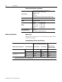
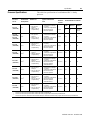
Allen-Bradley Enhanced PLC-5 Programmable Controller (Cat. No. 1785-L11B, -L20B, -L30B, -L40B, -L40L, -L60B, -L60L, -L80B) Quick Start Important User Information Because of the variety of uses for the products described in this publication, those responsible for the application and use of this control equipment must satisfy themselves that all necessary steps have been taken to assure that each application and use meets all performance and safety requirements, including any applicable laws, regulations, codes and standards. The illustrations, charts, sample programs and layout examples shown in this guide are intended solely for purposes of example. Since there are many variables and requirements associated with any particular installation, Allen-Bradley does not assume responsibility or liability (to include intellectual property liability) for actual use based upon the examples shown in this publication. Allen-Bradley publication SGI-1.1, Safety Guidelines for the Application, Installation, and Maintenance of Solid-State Control (available from your local Allen-Bradley office), describes some important differences between solid-state equipment and electromechanical devices that should be taken into consideration when applying products such as those described in this publication. Reproduction of the contents of this copyrighted publication, in whole or in part, without written permission of Allen-Bradley Company, Inc., is prohibited. Throughout this manual we use notes to make you aware of safety considerations: ! ATTENTION: Identifies information about practices or circumstances that can lead to personal injury or death, property damage or economic loss. Attention statements help you to: • identify a hazard • avoid the hazard • recognize the consequences Important: Identifies information that is critical for successful application and understanding of the product. PLC, PLC-5/11, -5/20, -5/30, -5/40, -5/40L, -5/60, -5/80, PLC-5, and DH+ are trademarks of Allen-Bradley Company, Inc Preface Preface Read this preface to familiarize yourself with the rest of the manual. This preface covers the following topics: • who should use this manual • the purpose of this manual • how to use this manual • conventions used in this manual • Rockwell Automation support Who Should Use This Manual To use this manual, you should understand programmable controllers and be able to interpret the ladder logic instructions required to control your application. For more information, see the documents listed on the following page or contact your local Rockwell Automation representative. Purpose of This Manual This manual is for users of the Enhanced PLC-5® processor. It: How to Obtain a User Manual • presents you with the basic information you need to get your system up and running • provides “memory jogger” information, such as specific bit and switch settings for modules • includes high-level procedures with cross-references to other manuals for more detail There is a user manual associated with this product that contains detailed information about configuring, programming, and using a PLC-5 processor. To obtain a copy of the Enhanced and Ethernet PLC-5 Programmable Controllers User Manual, publication number 1785-6.5.12, you can either: • view or download an electronic version from the internet: www.theautomationbookstore.com • purchase a hardcopy from the internet: www.theautomationbookstore.com • contact your local distributor or Rockwell Automation representative to place an order. See the table on the next page for other related publications. Publication 1785-10.4 - November 1998 P-2 Preface Related Documentation The following documents contain additional information concerning the products discussed in this manual. For more information about: See this document: Publication number: Enhanced PLC-5 programmable controllers Enhanced and Ethernet PLC-5 Programmable Controllers User Manual 1785-6.5.12 Universal 1771 I/O chassis Universal I/O Chassis Installation Instructions 1771-2.210 power supply Power Supply Modules (1771-P4S, -P6S, -P4S1, -P6S1) Installation Instructions 1771-2.135 DH+® network Enhanced and Ethernet PLC-5 Programmable Controllers User Manual 1785-6.5.12 Data Highway/Data Highway Plus/Data Highway II/Data Highway-485 Cable Installation Instructions 1770-6.2.2 1784-KTx Communication Interface Card User Manual 1784-6.5.22 Allen-Bradley Publication Index (for your specific communication card) SD499 cables Enhanced and Ethernet PLC-5 Programmable Controllers User Manual 1785-6.5.12 batteries Allen-Bradley Guidelines for Lithium Battery Handling and Disposal AG-5.4 grounding and wiring Allen-Bradley programmable controllers Allen-Bradley Programmable Controller Wiring and Grounding Guidelines 1770-4.1 current Allen-Bradley documentation, including ordering instructions Allen-Bradley Publication Index SD499 terms and definitions Allen-Bradley Industrial Automation Glossary AG-7.1 communication cards Common Techniques Used in This Manual We use the following conventions throughout this manual: • Bulleted lists provide information, not procedural steps. • Numbered lists provide sequential steps or hierarchical information. We use this symbol to indicate additional references you can use when you need more information about a particular topic. Publication 1785-10.4 - November 1998 Preface Rockwell Automation Support P-3 Rockwell Automation offers support services worldwide, with over 75 sales/support offices, 512 authorized distributors, and 260 authorized systems integrators located throughout the United States alone, plus Rockwell Automation representatives in every major country in the world. Local Product Support Contact your local Rockwell Automation representative for: • sales and order support • product technical training • warranty support • support service agreements Technical Product Assistance If you need to contact Rockwell Automation for technical assistance, call your local Rockwell Automation representative. Your Questions or Comments about This Manual If you discover a problem with this manual, please notify us of it by completing and sending the enclosed Publication Problem Report (at the back of this manual). If you have any suggestions about how we can make this manual more useful to you, please contact us at the address below: Allen-Bradley Company, Inc. Automation Group Technical Communication 1 Allen-Bradley Drive Mayfield Heights, OH 44124-6118 Telephone: (440) 646-5000 FAX: (440) 646-4320 Publication 1785-10.4 - November 1998 Table of Contents Overview Chapter 1 What You Need to Do . . . . . . . . . . . . . . . . . . . . . . . . . . . . . . . . . . . . . . 1-1 Identifying the Processor’s Front Panel Components . . . . . . . . . . . . . . 1-2 Components You Need . . . . . . . . . . . . . . . . . . . . . . . . . . . . . . . . . . . . . 1-4 Compliance to European Union Directives . . . . . . . . . . . . . . . . . . . . . . 1-4 EMC Directive. . . . . . . . . . . . . . . . . . . . . . . . . . . . . . . . . . . . . . . . . . 1-4 Low Voltage Directive . . . . . . . . . . . . . . . . . . . . . . . . . . . . . . . . . . . 1-4 Set up the Hardware Chapter 2 Install the Hardware. . . . . . . . . . . . . . . . . . . . . . . . . . . . . . . . . . . . . . . . 2-2 Configure the I/O Chassis . . . . . . . . . . . . . . . . . . . . . . . . . . . . . . . . . 2-2 Ground the I/O Chassis . . . . . . . . . . . . . . . . . . . . . . . . . . . . . . . . . . . 2-4 Install the Power Supply . . . . . . . . . . . . . . . . . . . . . . . . . . . . . . . . . . 2-4 Install the PLC-5 Processor . . . . . . . . . . . . . . . . . . . . . . . . . . . . . . . . 2-5 Power Up the System. . . . . . . . . . . . . . . . . . . . . . . . . . . . . . . . . . . . . 2-6 Install the I/O Modules . . . . . . . . . . . . . . . . . . . . . . . . . . . . . . . . . . . 2-6 Connect the Personal Computer to the PLC-5 Processor . . . . . . . . . . . 2-6 Set up the Software Chapter 3 Install the Software and Set Up the Programming System . . . . . . . . . . 3-1 Start the Programming Software . . . . . . . . . . . . . . . . . . . . . . . . . . . . . . 3-1 Power Up the System. . . . . . . . . . . . . . . . . . . . . . . . . . . . . . . . . . . . . . . 3-2 Troubleshoot the Processor System Specifications Chapter 4 Use the PLC-5 Processor Status Indicators . . . . . . . . . . . . . . . . . . . . . . 4-1 Troubleshoot General Problems . . . . . . . . . . . . . . . . . . . . . . . . . . . . 4-1 Troubleshoot the Processor Communication Channels . . . . . . . . . . . 4-2 Appendix A General. . . . . . . . . . . . . . . . . . . . . . . . . . . . . . . . . . . . . . . . . . . . . . . . . Battery Specification . . . . . . . . . . . . . . . . . . . . . . . . . . . . . . . . . . . . . . Battery Type . . . . . . . . . . . . . . . . . . . . . . . . . . . . . . . . . . . . . . . . . . Average Battery Lifetime Specifications. . . . . . . . . . . . . . . . . . . . . Processor Specifications . . . . . . . . . . . . . . . . . . . . . . . . . . . . . . . . . . . A-1 A-2 A-2 A-2 A-3 Publication 1785-10.4 - November 1998 Chapter 1 Overview This quick start is designed to provide you with the information you need to get your system up and running quickly. Use this document if you are knowledgeable about Enhanced PLC-5 products, but may not have used one or more of them recently. The information we provide is geared to “jog your memory”. What You Need to Do If you need more information, see the Enhanced and Ethernet PLC-5 Programmable Controllers User Manual, publication number 1785-6.5.12 (see page P-1 for information about how to obtain a copy of this manual). PC with Programming Software Set up the Hardware (Chapter 2) Set up the Software (Chapter 3) PLC-5/20 Processor Internal Power Supply Troubleshoot the Processor System (Chapter 4) Data Highway Plus Publication 1785-10.4 - November 1998 1-2 Overview Identifying the Processor’s Front Panel Components These pictures show the Enhanced PLC-5 processor front panel components. PLC-5/11, -5/20, and -5/26 Processor Front Panel PLC-5/11 Processor battery indicator (red when the battery is low) processor RUN/FAULT indicator (green when running; red when faulted) keyswitch; selects processor mode force indicator (amber when I/O forces are enabled) channel 0 communication status indicator (green when the channel is communicating) channel 0-25-pin D-shell serial port; supports standard EIA RS-232C and RS-423 and is RS-422A compatible Use this port with ASCII or DF1 full-duplex, half-duplex master, and half-duplex slave protocols. The port’s default configuration supports processor programming: DF1 point-to-point 2400 bps no parity Install memory module here. one stop-bit BCC error check no handshaking Install battery here channel 1A status indicator (lights green and red) channel 1B status indicator (lights green and red) 8-pin mini-DIN, DH+ programming terminal connection parallel to channel 1A channel 1B communication port; its default configuration is remote I/O scanner channel 1A communication port; for the PLC-5/11 processor, the default configuration is DH+ PLC-5 family member designation channel 1A communication port; this 3-pin port is a dedicated DH+ port PLC-5/30 Processor Front Panel battery indicator (lights red when the battery is low) processor RUN/FAULT indicator (green when running; red when faulted) keyswitch; selects processor mode channel 1A status indicator (lights green and red) 8-pin mini-DIN, DH+ programming terminal connection parallel to channel 1A channel 1A communication port; its default configuration is DH+ channel 1B communication port; its default configuration is remote I/O scanner force indicator (amber when I/O forces are enabled) channel 0 communication status indicator (green when the channel is communicating) channel 0-25-pin D-shell serial port; supports standard EIA RS-232C and RS-423 and is RS-422A compatible Use this port with ASCII or DF1 full-duplex, half-duplex master, and half-duplex slave protocols. The port’s default configuration supports processor programming: DF1 point-to-point one stop-bit 2400 bps BCC error check no parity no handshaking channel 1B status indicator (lights green and red) Install memory module here Use these labels to write information about the channel: communication mode, station addresses, etc. Install battery here PLC-5 family member designation Publication 1785-10.4 - November 1998 Overview 1-3 PLC-5/40, -5/46, -5/60, -5/80, and -5/86 Processor Front Panels battery indicator (red when the battery is low) processor RUN/FAULT indicator (green when running; red when faulted) keyswitch; selects processor mode channel 2A status indicator (lights green and red) 8-pin mini-DIN, DH+ programming terminal connection parallel to channel 2A when channel 2A is configured for DH+ communications force indicator (amber when I/O forces are enabled) channel 0 communication status indicator (green when the channel is communicating) channel 2B status indicator (lights green and red) channel 0-25-pin D-shell serial port; supports standard EIA RS-232C and RS-423 and is RS-422A compatible channel 2A communication port; its default configuration is unused channel 2B communication port; its default configuration is unused channel 1A status indicator (lights green and red) 8-pin mini-DIN, DH+ programming terminal connection parallel to channel 1A channel 1A communication port; its default configuration is DH+ Use this port with ASCII or DF1 full-duplex, half-duplex master, and half-duplex slave protocols. The port’s default configuration supports processor programming: DF1 point-to-point 2400 bps no parity one stop-bit BCC error check no handshaking channel 1B status indicator (lights green and red) Use these labels to write information about the channel: communication mode, station addresses etc. Install memory module here channel 1B communication port; its default configuration is remote I/O scanner PLC-5 family member designation Install battery here ATTENTION: Make sure you understand the anti-static environment. ! The processor is shipped in a static-shielded container to guard against electrostatic damage. Electrostatic discharge can damage integrated circuits or semiconductors in the processor module if you touch backplane connector pins. It can also damage the module when you set configuration plugs or switches inside the module. Avoid electrostatic damage by observing the following precautions. • Remain in contact with an approved ground point while handling the module (by wearing a properly grounded wrist strap). • Do not touch the backplane connector or connector pins. • When not in use, keep the module in its static-shielded container. Wrist strap Publication 1785-10.4 - November 1998 1-4 Overview Components You Need Product name: Catalog number: Hardware Enhanced PLC-5 processor with 2 keys Lithium Battery (in a clear bag) I/O chassis Power supply 1785-L11B, -L20B, -L30B, -L40B, -L40L, -L60B, -L60L, -L80B 1770-XYC 1771-A1B, -A2B, -A3B, -A3B1, -A4B 1771-P4S, -P6S, -P4S1, -P6S1 Programming System PC PLC-5 programming software communication module Check your programming software documentation for system requirements, such as memory, etc. Choose a programming software package that is compatible with Enhanced PLC-5 processors. DH+ interface and interconnect cable Important: In this manual, we assume you are using a brand-new Enhanced PLC-5 processor out of the box. Compliance to European Union Directives If this product has the CE mark it is approved for installation within the European Union and EEA regions. It has been designed and tested to meet the following directives. EMC Directive This product is tested to meet Council Directive 89/336/EEC Electromagnetic Compatibility (EMC) and the following standards, in whole or in part, documented in a technical construction file: • EN 50081-2EMC – Generic Emission Standard, Part 2 – Industrial Environment • EN 50082-2EMC – Generic Immunity Standard, Part 2 – Industrial Environment This product is intended for use in an industrial environment. Low Voltage Directive This product is tested to meet Council Directive 73/23/EEC Low Voltage, by applying the safety requirements of EN 61131-2 Programmable Controllers, Part 2 – Equipment Requirements and Tests. For specific information required by EN 61131-2, see the appropriate sections in this publication, as well as the following Allen-Bradley publications: Publication 1785-10.4 - November 1998 • Industrial Automation Wiring and Grounding Guidelines For Noise Immunity, publication 1770-4.1 • Guidelines for Handling Lithium Batteries, publication AG-5.4 • Automation Systems Catalog Chapter 2 Set up the Hardware 1 Install the the hardware Install hardware (page 2-2) (page 2-2) 2 Connect the Connect the personal personalcomputer computer to the PLC-5 to the PLC-5 processor processor (page 2-6) (page 2-6) PC with Programming Software PLC-5/20 Processor Internal Power Supply Data Highway Plus For more information, see the Enhanced and Ethernet User Manual, publication number 1785-6.5.12. Publication 1785-10.4 - November 1998 2-2 Set up the Hardware Install the Hardware 1 Configure the I/O Chassis Set the backplane switches. Pressed in at top ON (closed) Switch Pressed in at bottom OFF (open) Last State 1 O1 N O F F on Outputs of this I/O chassis remain in their last state when a hardware failure occurs. 1 off Outputs of this I/O chassis are turned off when a hardware failure occurs. 1 2 3 Always Off Switches Addressing 4 5 6 7 8 4 5 off off 2 - slot off on 1 - slot on off 1/2 - slot on on Not allowed Switches 6 off 7 off on on on off Switch 8 EEPROM Transfer EEPROM memory transfer to processor memory at power-up. `2, 3´ EEPROM memory transfers to processor memory if processor memory not valid. EEPROM memory does not transfer to processor memory. ˆ4 Processor Memory Protection off Processor memory protection disabled. on 5 Processor memory protection enabled. ˜ 1 Regardless of this switch setting, outputs are turned off when any of the following occurs: - processor detects a runtime error - an I/O chassis backplane fault occurs - you select program or test mode - you set a status file bit to reset a local rack 2` If an EEPROM module is not installed and processor memory is valid, the processor's PROC LED indicator blinks, and the processor sets S:11/9, bit 9 in the major fault status word. To clear this fault, change the processor from program mode to run mode and back to program mode. 3´ If the processor's keyswitch is set in REMote, the processor enters remote RUN after it powers up and has its memory updated by the EEPROM module. 4ˆ A processor fault (solid red PROC LED) occurs if processor memory is not valid. 5˜ You cannot clear processor memory when this switch is on. 19309 Publication 1785-10.4 - November 1998 Set up the Hardware 2-3 2 Set the power supply configuration jumper. Are you using a power supply module in the chassis? 3 Install the keying bands. PLC-5/20 Processor Y N Keying Bands YN O 1 N O F F 2 3 4 2 4 6 8 10 12 14 16 18 20 22 24 26 28 30 32 34 36 38 40 42 44 46 48 50 52 54 56 5 6 7 8 between - 40 & 42 - 54 & 56 20609-M Configuring an I/O rack for a local PLC-5 is different than configuring a remote I/O rack using a 1771-ASB module. For more information about configuring a remote I/O rack using a 1771-ASB module, see the following: • Remote I/O Adapter Module User Manual, publication number, 1771-6.5.83 • Enhanced and Ethernet PLC-5 Programmable Controllers User Manual, publication number 1785-6.5.12 For more information, see the Universal I/O Chassis installation instructions, publication number 1771-2.10. Publication 1785-10.4 - November 1998 2-4 Set up the Hardware Ground the I/O Chassis Enclosure Grounding Electrode Conductor Ground Bus To Grounding Electrode System Ground Lug Nut and Captive Washer Star Washer I/O Chassis Wall Ground Lug 20626-M For more information, see the Allen-Bradley Programmable Controller Wiring and Grounding Guidelines, publication number 1770-4.1. Install the Power Supply 1 Set the jumpers on the back side of the power supply like this: Locking Bar 2 Connect the power cord to the 120V ac connector of the power supply module. This side plugs into connector on the module. insert wire here insert wire here or place tool here place tool here 3 Install the power supply in the chassis 20619-M Publication 1785-10.4 - November 1998 and snap the module-locking bar over the modules Set up the Hardware 2-5 For more information, see the Power Supply Modules (1771-P4S, -P6S, -P4S1, -P6S1) Installation Instructions, publication number 1771-2.135 or the AC (120/220V) 16A Power Supply (1771-P7 Series B/C) Installation Instructions, publication number 1771-5.39. Install the PLC-5 Processor 1Define the DH+ Station Address of Channel 1A by setting switch assembly SW-1 on the back of the processor. (See the side of the processor if you want to use another address.) Locking Bar side view of processor Lift Ejector Tab PLC-5/20 Processor 1 2 3 4 5 67 Battery Connector Battery Cover side view down 57.6 Kbaud + Card Guides - up 230 Kbaud 20610-M For series E and later processors: use this switch to select baud rate For series D and earlier processors: this switch is always off 2 Specify the digital interface of channel 0. bottom view of PLC-5/11 and -5/20 processor Battery Front of Processor More More For detailed information about handling and disposing of the battery as well as other important guidelines, see publication AG-5.4. 1 2 3 4 5 6 7 8 9 10 For more information, see the Enhanced and Ethernet PLC-5 Programmable Controllers User Manual, publication number 1785-6.5.12. bottom view of PLC-5/30, -5/40, -5/40L, -5/60, -5/60L and -5/80 processor Front of Processor side view 1 2 3 4 5 6 7 8 9 10 OFF 3 To install the battery, slide the battery-side connector into the processor-side connector until you hear them snap together, and attach the battery cover. 4 Install the processor module. Publication 1785-10.4 - November 1998 2-6 Set up the Hardware Power Up the System Power up the system. Check the LED display on the processor. If your system is operating properly, the PROC LED should be steady red. If the PROC LED is not red, see chapter 4 for troubleshooting information before you install any I/O modules. Install the I/O Modules Locking Bar Install each I/O module and connect the wiring arm. Card Guides 20618-M For more information, see the installation instructions or user manual for the particular module you are installing. Connect the Personal Computer to the PLC-5 Processor Publication 1785-10.4 - November 1998 For more information, see: • Enhanced and Ethernet PLC-5 Programmable Controllers User Manual, publication number 1785-6.5.12 • the documentation provided with your communication card • Data Highway/Data Highway Plus/Data Highway II/Data Highway 485 Cable Installation Manual, publication 1770-6.2.2 Chapter 3 Set up the Software 1 Install the software 2 Start the programming software 3 Powerup the system The following instructions are general. For specific information, see the documentation set for your particular software package. Install the Software and Set Up the Programming System Before you install your programming software, make certain you meet the system requirements for that software – sufficient disk space, memory, etc. Then, follow the procedures outlined in the software documentation to install the software and configure communication. Start the Programming Software Start the programming software by following the procedures described in your programming software documentation. If you have difficulty, verify that the power supply is turned on. To monitor your system as you configure and run it, check the processor LED display for the following indicators: This LED: lights when: COMM you establish DH+ communication BATT no battery is installed or the battery voltage is low REM I/O you establish Remote I/O communication ADAPT the processor is in adapter mode FORCE forces are present in your ladder program Publication 1785-10.4- November 1998 3-2 Set up the Software Power Up the System Power up the system if you have not done so already. Check the LED display on the processor. If your system is operating properly, the PROC LED should be steady red and the message “Processor RAM is faulted. Press <Enter> to clear memory” should appear on the display. See the following table to proceed. If the PROC LED is not red, turn to chapter 4 for troubleshooting information. If your keyswitch is in this position: Publication 1785-10.4- November 1998 do this: PROGRAM Clear memory. The PROC LED should turn off. The software is in Program mode. REMOTE Clear memory. The PROC LED should turn off. The software is in Remote Program mode. RUN You see the message “No access or privilege violation” because you cannot clear memory in Run mode. Change the keyswitch position to Program or Remote and press <Enter> to clear memory. Chapter 4 Troubleshoot the Processor System 1 Use the PLC-5 Processor Status Indicators (page 4-1) BATT PROC FORCE COMM Use the PLC-5 Processor Status Indicators Troubleshoot General Problems Indicator Color Description Probable Cause Recommended Action BATT Red Battery low Battery low Replace battery within 10 days Off Battery is good Normal operation No action required Green (steady) Processor is in run mode and fully operational Normal operation No action required Green (blinking) Processor memory is being transferred to EEPROM Red (blinking) Major fault Run-time error • Check major fault bit in status file (S:11) for error definition • Clear fault bit, correct problem, and return to run mode Red (steady) Major fault • Processor memory has checksum error • Memory module error • Internal diagnostics have failed • Clear memory and reload program • Check backplane switch settings and/or insert correct memory module • Power down, reseat processor and power up; then, clear memory and reload your program. Replace EEPROM with new program; then, if necessary, replace the processor Off Processor is in program load or test mode or is not receiving power PROC BATT PROC FORCE COMM Check power supply and connections Publication 1785-10.4 - November 1998 4-2 Troubleshoot the Processor System Indicator Color Description Probable Cause Recommended Action FORCE Amber (steady) SFC and/or I/O forces enabled Normal operation No action required Amber (blinking) SFC and/or I/O forces present but not enabled Off SFC and/or I/O forces not present Off No transmission on channel 0 Normal operation if channel is not being used Green (blinking) Transmission on channel 0 Normal operation if channel is being used COMM Troubleshoot the Processor Communication Channels A B Indicator Color Channel Mode Description Probable Cause Recommended Action A or B Green (steady) Remote I/O Scanner Active Remote I/O link, all adapter modules are present and not faulted Normal operation No action required Remote I/O Adapter Communicating with scanner DH+ Processor is transmitting or receiving on DH+ link Remote I/O Scanner At least one adapter is faulted or has failed • Power off at remote rack • Cable broken • Restore power to the rack • Repair cable DH+ No other nodes on network Red (steady) Remote I/O Scanner Remote I/O Adapter DH+ Hardware fault Hardware error • Turn power off, then on. • Check that the software configurations match the hardware set-up. • Replace the processor. Red (blinking rapidly or slowly) Remote I/O Scanner Faulted adapters detected • Cable not connected or is broken • Power off at remote racks • Repair cable Green (blinking rapidly or slowly) A Off Publication 1785-10.4 - November 1998 • Restore power to racks DH+ Bad communication on DH+ Duplicate node detected Correct station address Remote I/O Scanner Remote I/O Adapter DH+ Channel offline Channel is not being used Place channel online if needed Appendix A Specifications General This table lists general specifications. Backplane Current PLC-5/11, -5/20, -5/30 . . . . . . . . . . . . . . 2.3 A PLC-5/40, -5/40L, -5/60, -5/60L -5/80 . . . . . . . . . . . . . . . . . . . . . . 3.3 A Heat Dissipation PLC-5/11, -5/20, -5/30 . . . . . . . . . . . . . . 41.30 BTU/hr PLC-5/40, -5/40L, -5/60, -5/60L -5/80 . . . . . . . . . . . . . . . . . . . . . . 59.04 BTU/hr Environmental Conditions Operating Temperature. . . . . . . 0 to 60° C (32-140° F) Storage Temperature . . . . . . . . –40 to 85° C (–40 to 185° F) Relative Humidity . . . . . . . . . . . 5 to 95% (without condensation) Shock Operating . . . . . . 30 g peak acceleration for 11±1 ms duration Non-operating . . . 50 g peak acceleration for 11±1 ms duration Vibration (operating and non-operating) 1 g @ 10 to 500 Hz 0.012 inches peak-to-peak displacement Time-of-Day Clock/Calendar1 Maximum Variations at 60° C. . ± 5 min per month Typical Variations at 20° C. . . . ± 20 s per month Timing Accuracy. . . . . . . . . . . . 1 program scan Battery 1770-XYC Memory Modules 1785-ME16 1785-ME32 Typical Discrete I/O Scan • • • • I/O Modules Bulletin 1771 I/O including 8-, 16-, 32-pt, and intelligent modules Hardware Addressing 2-slot • Any mix of 8-pt modules • 16-pt modules must be I/O pairs • No 32-pt modules 1-slot • Any mix of 8- or 16-pt modules • 32-pt modules must be I/O pairs 1/2-slot – Any mix of 8-,16-, or 32-pt modules 1 1785-ME64 1785-M100 0.5 ms / extended-local I/O adapter 10 ms / remote I/O rack at 57.6 kbps 7 ms / remote I/O rack at 115.2 kbps 3 ms / remote I/O rack at 230.4 kbps Please note that the Clock/Calendar will update appropriately each year, including the year 2000. Publication 1785-10.4 - November 1998 A-2 Specifications General Specifications (continued) Communication Location Keying Weight Agency Certification (when product is marked) Battery Specification • DH+ (trunk line: 3,048 cable-m (10,000 cable-ft); drop line: 30.4 cable-m (100 cable-ft) • DH using 1785-KA • Serial • remote I/O • extended-local I/O (PLC-5/40L and -5/60L processors only) 1771-A1B, -A2B, A3B, -A3B1, -A4B, chassis, left-most slot • Between 40 and 42 • Between 54 and 56 PLC-5/20 1.21 kg (2.7 lbs) PLC-5/30 1.20 kg (2.6 lbs) PLC-5/40, -5.40L 1.42 kg (3.1 lbs) PLC-5/60, -5/60L 1.42 kg (3.1 lbs) PLC-5/80 1.42 kg (3.1 lbs) • CSA Class I, Division 2, Groups A, B, C, D • UL listed • CE marked for all applicable directives Battery Type Enhanced PLC-5 processors use 1770-XYC batteries which contain 0.65 grams of lithium. Average Battery Lifetime Specifications Worst-case Battery Life Estimates Battery used in this processor: At this temperature: Power off 100%: Power off 50%: Battery Duration after the LED lights1 PLC-5/11, -5/20 60°C 256 days 1.4 years 11.5 days 25°C 2 years 4 years 47 days 60°C 84 days 150 days 5 days 25°C 1 year 1.2 years 30 days PLC-5/30, -5/40, -5/40L, -5/60, -560L, -5/80 1 The battery indicator (BATT) warns you when the battery is low. These durations are based on the battery supplying the only power to the processor (power to the chassis is off) once the LED first lights. Publication 1785-10.4 - November 1998 Specifications Processor Specifications Processor/ Cat. No. PLC-5/11 (1785-L11B) PLC-5/20 (1785-L20B) PLC-5/26 (1785-L26B) PLC-5/30 (1785-L30B) PLC-5/40 (1785-L40B) PLC-5/40L (1785-L40L) PLC-5/60 (1785-L60B) PLC-5/60L (1785-L60L) PLC-5/80 (1785-L80B) 1 2 3 Maximum User Memory Words A-3 This table lists specifications of each Enhanced PLC-5 family processor. Maximum I/O Types of Communication Ports Maximum Number of I/O Racks Maximum Number of I/O Chassis Total Ext Local Remote 4 (0-3) 5 0 4 (must be rack 3) • 1 DH+ (Fixed) • 1 DH+/Remote I/O (Adapter or Scanner) • 1 serial port, configurable for RS-232 and 423 and RS-422A compatible 4 (0-3) 13 0 12 32 K • 1024 (any mix or analog) or • 1024 in + 1024 out (complementary) • 2 DH+/Remote I/O (Adapter or Scanner) • 1 serial port, configurable for RS-232 and 423 and RS-422A compatible 8 (0-7) 29 0 28 48 K1 • 2048 (any mix or analog) or • 2048 in + 2048 out (complementary) • 4 DH+/Remote I/O (Adapter or Scanner) • 1 serial port, configurable for RS-232 and 423 and RS-422A compatible 16 (0-17) 61 0 60 48 K1 • 2048 (any mix or analog) or • 2048 in + 2048 out (complementary) • 2 DH+/Remote I/O (Adapter or Scanner) • 1 serial port, configurable for RS-232 and 423 and RS-422A compatible • 1 Extended-local I/O 16 (0-17) 61 16 60 64 K2 • 3072 (any mix or analog) or • 3072 in + 3072 out (complementary) • 4 DH+/Remote I/O (Adapter or Scanner) • 1 serial port, configurable for RS-232 and 423 and RS-422A compatible 24 (0-27) 93 0 92 64 K2 • 3072 (any mix or analog) or • 3072 in + 3072 out (complementary) • 2 DH+/Remote I/O (Adapter or Scanner) • 1 serial port, configurable for RS-232 and 423 and RS-422A compatible • 1 Extended-local I/O 24 (0-27) 81 16 64 • 3072 (any mix or analog) or • 3072 in + 3072 out (complementary) • 4 DH+/Remote I/O (Adapter or Scanner) • 1 serial port, configurable for RS-232 and 423 and RS-422A compatible 24 (0-27) 93 0 92 • 512 (any mix or analog) or • 384 in + 384 out (complementary) • 1 DH+/Remote I/O (Adapter or Scanner) • 1 serial port, configurable for RS-232 and 423 and RS-422A compatible 16K • 512 (any mix or analog) or • 512 in + 512 out (complementary) 8K 100 3 The PLC-5/40 and -5/40L processors have a limit of 32K words per data table file. The PLC-5/60 and -5/60L processors have a limit of 56K words per program file and 32K words per data table file. The PLC-5/80 processors have 64K words of total data table space with a limit of 56K words per program file and 32K words per data table file. Publication 1785-10.4 - November 1998 A-4 Specifications CSA Hazardous Location Approval Approbation d’utilisation dans des emplacements dangereux par la CSA CSA certifies products for general use as well as for use in hazardous locations. Actual CSA certification is indicated by the product label as shown below, and not by statements in any user documentation. La CSA certifie les produits d’utilisation générale aussi bien que ceux qui s’utilisent dans des emplacements dangereux. La certification CSA en vigueur est indiquée par l’étiquette du produit et non par des affirmations dans la documentation à l’usage des utilisateurs. Example of the CSA certification product label ® Exemple d'étiquette de certification d'un produit par la CSA CL 1 DIV 2 GP A,B,C,D TEMP ® CL 1 DIV 2 GP A,B,C,D TEMP To comply with CSA certification for use in hazardous locations, the following information becomes a part of the product literature for CSA-certified Allen-Bradley industrial control products. • This equipment is suitable for use in Class I, Division 2, Groups A, B, C, D, or non-hazardous locations only. • The products having the appropriate CSA markings (that is, Class I Division 2, Groups A, B, C, D), are certified for use in other equipment where the suitability of combination (that is, application or use) is determined by the CSA or the local inspection office having jurisdiction. Pour satisfaire à la certification de la CSA dans des endroits dangereux, les informations suivantes font partie intégrante de la documentation des produits industriels de contrôle Allen-Bradley certifiés par la CSA. • Cet équipement convient à l’utilisation dans des emplacements de Classe 1, Division 2, Groupes A, B, C, D, ou ne convient qu’à l’utilisation dans des endroits non dangereux. • Les produits portant le marquage approprié de la CSA (c’est à dire, Classe 1, Division 2, Groupes A, B, C, D) sont certifiés à l’utilisation pour d’autres équipements où la convenance de combinaison (application ou utilisation) est déterminée par la CSA ou le bureau local d’inspection qualifié. Important: Due to the modular nature of a PLC control system, the product with the highest temperature rating determines the overall temperature code rating of a PLC control system in a Class I, Division 2 location. The temperature code rating is marked on the product label as shown. Important: Par suite de la nature modulaire du système de contrôle PLC, le produit ayant le taux le plus élevé de température détermine le taux d’ensemble du code de température du système de contrôle d’un PLC dans un emplacement de Classe 1, Division 2. Le taux du code de température est indiqué sur l’étiquette du produit. Temperature code rating ® CL 1 DIV 2 GP A,B,C,D TEMP Taux du code de température ® Look for temperature code rating here CL 1 DIV 2 GP A,B,C,D TEMP Le taux du code de température est indiqué ici The following warnings apply to products having CSA certification for use in hazardous locations. Les avertissements suivants s’appliquent aux produits ayant la certification CSA pour leur utilisation dans des emplacements dangereux. ATTENTION: Explosion hazard – • Substitution of components may impair suitability for Class I, Division 2. • Do not replace components unless power has been switched off or the area is known to be non-hazardous. • Do not disconnect equipment unless power has been switched off or the area is known to be non-hazardous. • Do not disconnect connectors unless power has been switched off or the area is known to be non-hazardous. Secure any user-supplied connectors that mate to external circuits on an Allen-Bradley product using screws, sliding latches, threaded connectors, or other means such that any connection can withstand a 15 Newton (3.4 lb.) separating force applied for a minimum of one minute. AVERTISSEMENT: Risque d’explosion – • La substitution de composants peut rendre ce matériel inacceptable pour les emplacements de Classe I, Division 2. • Couper le courant ou s’assurer que l’emplacement est désigné non dangereux avant de remplacer les composants. • Avant de débrancher l’équipement, couper le courant ou s’assurer que l’emplacement est désigné non dangereux. • Avant de débrancher les connecteurs, couper le courant ou s’assurer que l’emplacement est reconnu non dangereux. Attacher tous connecteurs fournis par l’utilisateur et reliés aux circuits externes d’un appareil Allen-Bradley à l’aide de vis, loquets coulissants, connecteurs filetés ou autres moyens permettant aux connexions de résister à une force de séparation de 15 newtons (3,4 lb. - 1,5 kg) appliquée pendant au moins une minute. ! Publication 1785-10.4 - November 1998 ! Allen-Bradley Publication Problem Report If you find a problem with our documentation, please complete and return this form Enhanced PLC-5 Programmable Controller Quick Start Pub. Name 1785-L11B, -L20B, -L30B, -L40B, Cat. No. L40L, -L60B, -L60L, -L80B Pub. No. 1785-10.4 Pub. Date Check Problem(s) Type: November 1998 Part No. Describe Problem(s): 955133-87 Internal Use Only Technical Accuracy text Completeness procedure/step illustration definition info in manual example guideline feature (accessibility) explanation other What information is missing? illustration info not in manual Clarity What is unclear? Sequence What is not in the right order? Other Comments Use back for more comments. Your Name Location/Phone Return to: Marketing Communications, Allen-Bradley Co., 1 Allen-Bradley Drive, Mayfield Hts., OH 44124-6118Phone: (440)646-3166 FAX: (440)646-4320 Publication ICCG-5.21 - August 1995 PN 955107-82 PLEASE FASTEN HERE (DO NOT STAPLE) PLEASE FOLD HERE NO POSTAGE NECESSARY IF MAILED IN THE UNITED STATES BUSINESS REPLY MAIL FIRST-CLASS MAIL PERMIT NO. 18235 CLEVELAND OH POSTAGE WILL BE PAID BY THE ADDRESSEE 1 ALLEN BRADLEY DR MAYFIELD HEIGHTS OH 44124-9705 PLEASE REMOVE Other Comments Publication 1785-10.4 - November 1998 Supersedes Publication 1785-10.4 - December 1996 PN 955133-87 1998 Rockwell International Corp. All Rights Reserved. Printed in USA