1
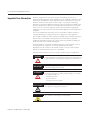
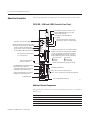
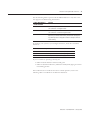
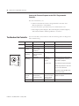
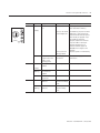
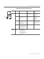
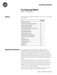
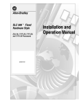
Installation Instructions
Ethernet PLC-5 Programmable Controllers
Catalog Numbers 1785-L20E, 1785-L40E, 1785-L80E, Series F
Contents
About This Publication
For This Topic
See Page
About This Publication
1
Related User Manual
5
About the Controllers
6
Install the System Hardware
13
Troubleshoot the Controller
20
Controller Specifications
24
Rockwell Automation Support
Back cover
This document describes how to install and troubleshoot your Ethernet PLC-5
programmable controller. For more information, see the documents listed on
the following page or contact your local Rockwell Automation representative.
These installation instructions:
• provide the basic information you need to get your system up and
running.
• provide specific bit and switch settings for modules.
• include high-level procedures with cross-references to other manuals for
more detail.
IMPORTANT
1
In this document, we assume you are using a Series F
Ethernet PLC-5 programmable controller.
Publication 1785-IN063B-EN-P - January 2006
2
Ethernet PLC-5 Programmable Controllers
Important User Information
Solid state equipment has operational characteristics differing from those of
electromechanical equipment. Safety Guidelines for the Application, Installation and
Maintenance of Solid State Controls (Publication SGI-1.1 available from your local
Rockwell Automation sales office or online at http://www.ab.com/manuals/gi)
describes some important differences between solid state equipment and hard-wired
electromechanical devices. Because of this difference, and also because of the wide
variety of uses for solid state equipment, all persons responsible for applying this
equipment must satisfy themselves that each intended application of this equipment is
acceptable.
In no event will Rockwell Automation, Inc. be responsible or liable for indirect or
consequential damages resulting from the use or application of this equipment.
The examples and diagrams in this manual are included solely for illustrative purposes.
Because of the many variables and requirements associated with any particular
installation, Rockwell Automation, Inc. cannot assume responsibility or liability for
actual use based on the examples and diagrams.
No patent liability is assumed by Rockwell Automation, Inc. with respect to use of
information, circuits, equipment, or software described in this manual.
Reproduction of the contents of this manual, in whole or in part, without written
permission of Rockwell Automation, Inc. is prohibited.
Throughout this manual we use notes to make you aware of safety considerations.
WARNING
IMPORTANT
ATTENTION
Identifies information about practices or circumstances that can
cause an explosion in a hazardous environment, which may lead
to personal injury or death, property damage, or economic loss.
Identifies information that is critical for successful application
and understanding of the product.
Identifies information about practices or circumstances that can
lead to personal injury or death, property damage, or economic
loss. Attentions help you:
• identify a hazard
• avoid a hazard
• recognize the consequence
Publication 1785-IN063B-EN-P - January 2006
SHOCK HAZARD
Labels may be located on or inside the equipment to alert people
that dangerous voltage may be present.
BURN HAZARD
Labels may be located on or inside the equipment to alert people
that surfaces may be dangerous temperatures.
Ethernet PLC-5 Programmable Controllers
3
Environment and Enclosure
ATTENTION
• This equipment is intended for use in a Pollution Degree 2
industrial environment, in overvoltage Category II
applications (as defined in IEC publication 60664-1), at
altitudes up to 2000 meters without derating.
• This equipment is considered Group 1, Class A industrial
equipment according to IEC/CISPR Publication 11. Without
appropriate precautions, there may be potential difficulties
ensuring electromagnetic compatibility in other
environments due to conducted as well as radiated
disturbance.
• This equipment is supplied as “open type” equipment. It
must be mounted within an enclosure that is suitably
designed for those specific environmental conditions that will
be present and appropriately designed to prevent personal
injury resulting from accessibility to live parts. The interior of
the enclosure must be accessible only by the use of a tool.
Subsequent sections of this publication may contain
additional information regarding specific enclosure type
ratings that are required to comply with certain product
safety certifications.
• Besides this publication, see:
– Industrial Automation Wiring and Grounding Guidelines,
Allen-Bradley publication 1770-4.1, for additional
installation requirements.
– NEMA Standards publication 250 and IEC publication
60529, as applicable, for explanations of the degrees of
protection provided by different types of enclosure.
Prevent Electrostatic Discharge
ATTENTION
This equipment is sensitive to electrostatic discharge that can
cause internal damage and affect normal operation. Follow
these guidelines when you handle this equipment.
• Touch a grounded object to discharge potential static.
• Wear an approved grounding wrist strap.
• Do not touch connectors or pins on component
boards.
• Do not touch circuit components inside the equipment.
• Use a static-safe workstation, if available.
• Store the equipment in appropriate static-safe
packaging when not in use.
Publication 1785-IN063B-EN-P - January 2006
4
Ethernet PLC-5 Programmable Controllers
North American Hazardous Location Approval
The following information applies when operating this
equipment in hazardous locations:
Informations sur l’utilisation de cet équipement en
environnements dangereux :
Products marked “CL I, DIV 2, GP A, B, C, D” are suitable for use in
Class I Division 2 Groups A, B, C, D, Hazardous Locations and
nonhazardous locations only. Each product is supplied with
markings on the rating nameplate indicating the hazardous location
temperature code. When combining products within a system, the
most adverse temperature code (lowest “T” number) may be used
to help determine the overall temperature code of the system.
Combinations of equipment in your system are subject to
investigation by the local Authority Having Jurisdiction at the time
of installation.
Les produits marqués “CL I, DIV 2, GP A, B, C, D” ne conviennent
qu’à une utilisation en environnements de Classe I Division 2
Groupes A, B, C, D dangereux et non dangereux. Chaque produit est
livré avec des marquages sur sa plaque d’identification qui
indiquent le code de température pour les environnements
dangereux. Lorsque plusieurs produits sont combinés dans un
système, le code de température le plus défavorable (code de
température le plus faible) peut être utilisé pour déterminer le code
de température global du système. Les combinaisons
d’équipements dans le système sont sujettes à inspection par les
autorités locales qualifiées au moment de l’installation.
RISQUE D’EXPLOSION
EXPLOSION HAZARD
WARNING
• Do not disconnect equipment unless
power has been removed or the area is
known to be nonhazardous.
• Do not disconnect connections to this
equipment unless power has been
removed or the area is known to be
nonhazardous. Secure any external
connections that mate to this equipment
by using screws, sliding latches,
threaded connectors, or other means
provided with this product.
• Substitution of components may impair
suitability for Class I, Division 2.
• If this product contains batteries, they
must only be changed in an area known
to be nonhazardous.
Publication 1785-IN063B-EN-P - January 2006
AVERTISSEMENT
• Couper le courant ou s’assurer que
l’environnement est classé non
dangereux avant de débrancher
l'équipement.
• Couper le courant ou s'assurer que
l’environnement est classé non
dangereux avant de débrancher les
connecteurs. Fixer tous les connecteurs
externes reliés à cet équipement à
l'aide de vis, loquets coulissants,
connecteurs filetés ou autres moyens
fournis avec ce produit.
• La substitution de composants peut
rendre cet équipement inadapté à une
utilisation en environnement de Classe
I, Division 2.
• S’assurer que l’environnement est
classé non dangereux avant de changer
les piles.
Ethernet PLC-5 Programmable Controllers
Related User Manual
5
The related user manual contains detailed information about configuring,
programming, and using an Ethernet PLC-5 controller. To obtain a copy of
the Enhanced and Ethernet PLC-5 Programmable Controllers User Manual,
publication 1785-UM012, you can:
• view or download an electronic version from the Internet at
www.rockwellautomation.com/literature.
• contact your local distributor or Rockwell Automation representative to
place an order.
Additional Related Documentation
The following documents contain additional information related to the
products described in this document.
For More Information About
See This Publication
Number
Ethernet PLC-5 programmable controllers
Enhanced and Ethernet PLC-5 Programmable Controllers User
Manual
1785-UM012
Universal 1771 I/O chassis
Universal I/O Chassis Installation Instructions
1771-2.210
Power supply
Power Supply Modules (1771-P4S, -P6S, -P4S1, -P6S1)
Installation Instructions
1771-2.135
DH+ network, extended-local I/O
Enhanced and Ethernet PLC-5 Programmable Controllers User
Manual
1785-UM012
Data Highway/Data Highway Plus/Data Highway II/Data
Highway-485 Cable Installation Instructions
1770-6.2.2
Communication cards
1784-KTx Communication Interface Card User Manual
1784-6.5.22
Cables
Enhanced and Ethernet PLC-5 Programmable Controllers User
Manual
1785-UM012
Batteries
Allen-Bradley Guidelines for Lithium Battery Handling and
Disposal
AG-5.4
Grounding and wiring Allen-Bradley
programmable controllers
Allen-Bradley Programmable Controller Wiring and Grounding
Guidelines
1770-4.1
Terms and definitions
Allen-Bradley Industrial Automation Glossary
AG-7.1
Publication 1785-IN063B-EN-P - January 2006
6
Ethernet PLC-5 Programmable Controllers
About the Controllers
The following illustrations indicate the controller’s front panel components.
PLC-5/20E, -5/40E and -5/80E, Controller Front Panel
Battery Indicator (red when the battery is low)
Controller RUN/FAULT Indicator (green when
running; red when faulted)
Force Indicator (amber when I/O forces
are enabled)
Channel 0 Communication Status Indicator
(green when the channel is communicating)
Keyswitch - Selects Controller Mode
Channel 2 Ethernet Status Indicator (green when
functioning normally; red when not functioning)
STAT
Channel 2, Ethernet Transmit Indicators
(green when the channel is communicating
at either 100M or 10M communication rate)
100M
10M
Channel 0-25-pin D-shell serial port. Supports standard
CEIA RS-232C and RS-423 and is RS-422A compatible.
ETHERNET
Use this port with ASCII or DF1 full-duplex, half-duplex
master, and half-duplex slave protocols. The port's
default configuration supports controller programming:
Ethernet Channel 2 Communication
Port - RJ45 Connector
DF1 point-to-point
2400 bps
No parity
Channel 1A Status Indicator
(lights green and red)
One stop-bit
BCC error check
No handshaking
Channel 1B Status Indicator (lights green and red)
8-pin Mini-DIN, DH+ Programming Terminal
Connection Parallel to Channel 1A
Install Memory Module Here
Channel 1A Communication Port - Default
Configuration Is DH+ Communication
Use these labels to write information about the
channel, such as communication mode and station addresses.
Channel 1B Communication Port - Default
Configuration Is Remote I/O Scanner
Install Battery Here
PLC-5/40E
Programmable
Controller
PLC-5 Family Member Designation
43909
Additional System Components
Along with your controller, you need the following components to complete a
basic system.
Product
Lithium battery
1770-XYC
I/O chassis
1771-A1B, -A2B, -A3B, -A3B1, -A4B
Power supply
1771-P4S, -P6S, -P4S1, -P6S1
Personal computer
Publication 1785-IN063B-EN-P - January 2006
Cat. No.
Ethernet PLC-5 Programmable Controllers
7
New Features
The controllers contain an RJ-45 connector for the Channel 2 communication
port.
The controllers provide additional Channel 2 port configuration and status:
ENET Status
STAT
100M
ENET Transmit
10M
RJ45
Connector
•
•
•
•
•
•
•
BOOTP, DHCP, or Static entry of IP address
Auto Negotiate speed selection
Full/Half Duplex port setting
10/100 speed selection
Email client functionality
Enable/Disable HTTP Web Server
Enable/Disable SNMP functionality
To see or activate the new configuration and status features:
1. Open or create a project in RSLogix 5 software, version 7.1 or later.
2. Click on the Channel Configuration menu.
You see the Edit Channel Properties menu.
3. Click on the Channel 2 tab.
BOOTP, DHCP, or Static Entry of IP Address
As shown in the following screen capture, you can select between a static or
dynamic network configuration.
• The default is Dynamic Network Configuration Type and
Use BOOTP to obtain network configuration.
• If you choose a dynamic network configuration, you can change the
default BOOTP to DHCP.
• If you choose a static network configuration type, you must enter the IP
address.
Publication 1785-IN063B-EN-P - January 2006
8
Ethernet PLC-5 Programmable Controllers
Similarly, if you have a dynamic network configuration, DHCP or BOOTP
assigns the controller’s hostname. With a static configuration, you assign the
hostname.
When you create a hostname, consider these naming conventions.
• The hostname can be a text string up to 24 characters.
• The hostname can contain alpha (A to Z) numeric (0 to 9) and may
contain a period and minus sign.
• The first character must be an alpha character.
• The last character must not be a minus sign.
• You cannot use blank spaces or space characters.
• The hostname is not case-sensitive.
Auto Negotiate Speed Selection
In the Edit Channel 2 properties box, you can either leave the Auto Negotiate
box unchecked, which forces the port setting to a particular speed and duplex
port setting, or you may check the Auto Negotiate box, which lets the
controller negotiate a speed and duplex port setting.
If you check Auto Negotiate, the port setting lets you select the range of speed
and duplex settings that the controller negotiates. The default port setting with
Auto Negotiate checked is 10/100 Mbps Full Duplex/Half Duplex, which lets
the controller negotiate any of it’s four available settings. The following table
lists the order of negotiation for each setting.
Setting
100 Mbps
Full Duplex
100 Mbps
Half Duplex
10 Mbps
Full Duplex
10 Mbps
Half Duplex
10/100 Mbps Full Duplex/Half Duplex
1st
2nd
3rd
4th
100 Mbps Full Duplex or 100 Mbps Half Duplex
1st
2nd
100 Mbps Full Duplex or 10 Mbps Full Duplex
1st
100 Mbps Half Duplex or 10 Mbps Full Duplex
100 Mbps Full Duplex
100 Mbps Half Duplex
10 Mbps Full Duplex
10 Mbps Half Duplex Only
Publication 1785-IN063B-EN-P - January 2006
1st
3rd
2nd
3rd
2nd
3rd
1st
2nd
1st
2nd
1st
2nd
1st
Ethernet PLC-5 Programmable Controllers
9
The unchecked Auto Negotiate box and corresponding port settings are
shown below.
The checked Auto Negotiate box and corresponding port settings are shown
below.
Email Client Functionality
The controller is an email client that sends an email triggered by a message
instruction via a mail relay server. The controller uses standard SMTP protocol
to forward the email to the relay server. The controller does not receive email.
You must enter the SMTP Server’s IP address into the text box as shown in the
following dialog.
The controller supports login authentication. If you want the controller to
authenticate to the SMTP server, check the SMTP authentication box. If you
select authentication, you must also use a username and password for each
email.
Publication 1785-IN063B-EN-P - January 2006
10
Ethernet PLC-5 Programmable Controllers
To create an email:
1. Create a message instruction similar to the one below.
The destination (to), the reply (from), and the body (text) are stored as
strings in elements of separate ASCII string files.
If you want to send an email to a specific recipient when a controller
application generates an alarm or reaches a certain condition, program
the controller to send the message instruction to the destination of the
email.
2. Verify the rung.
3. Click on Setup Screen.
A dialog appears like the one below.
The three Data fields display the string values of the ST file element
addresses.
Publication 1785-IN063B-EN-P - January 2006
Ethernet PLC-5 Programmable Controllers
11
4. To send email, enter the appropriate information into the Data fields
and Username and Password, if Authentication is enabled.
Examine the Error Code (denoted in Hex) and Error Description areas within
the General tab to see if the message was successfully delivered.
Error Code (hex)
0x000
Description
Delivery successful to the mail relay server.
0x002
Resource unavailable. The email object was unable to obtain memory resources to initiate the SMTP session.
0x101
SMTP mail server IP address not configured.
0x102
To (destination) address not configured or invalid.
0x103
From (reply) address not configured or invalid.
0x104
Unable to connect to SMTP mail server.
0x105
Communication error with SMTP server.
0x106
Authentication required.
0x017
Authentication failed.
Channel 2 Status
To check the status of channel 2:
1. In your RSLogix 5 software project, click on Channel Status.
You see the Channel Status menu.
2. Click on the Channel 2 tab.
3. Click on the Port tab.
You see the status for each port configuration.
Publication 1785-IN063B-EN-P - January 2006
12
Ethernet PLC-5 Programmable Controllers
Enable/Disable HTTP Web Server
You can disable the HTTP web server functionality from within the Channel 2
Configuration by unchecking the HTTP Server Enable check box shown
below.
SNMP Server
Enabled
HTTP Server
Enabled
The default (checked box) lets you connect to the controller using a web
browser. Although this parameter can be downloaded to the controller as part
of a program download or changed and applied while online with the
controller, you must cycle power to the controller for the change to take affect.
Enable/Disable Simple Network Management Protocol (SNMP)
You can disable the controller’s SNMP functionality from within the Channel
2 Configuration by unchecking the SNMP Server Enable check box as shown
above.
The default (checked box) lets you connect to the controller using an SNMP
client. Although this parameter can be downloaded to the controller as part of
a program download or changed and applied while online with the controller,
you must cycle power to the controller for the change to take affect.
Publication 1785-IN063B-EN-P - January 2006
Ethernet PLC-5 Programmable Controllers
Install the System
Hardware
13
This illustration shows a basic Ethernet PLC-5 programmable controller
system.
PC with
Programming
Software
Ethernet PLC-5
Controller
Internal
Power Supply
Data Highway
Plus or Serial
Cable
43910
For more information, see the Enhanced and Ethernet PLC-5 Programmable
Controllers User Manual, publication 1785-UM012.
WARNING
WARNING
If you connect or disconnect any communications cable
with power applied to this module or any device on the
network, an electrical arc can occur. This could cause an
explosion in hazardous location installations.
Be sure that power is removed or the area is nonhazardous
before proceeding.
The local programming terminal port (circular mini-DIN
style programming terminal connection) is intended for
temporary use only and must not be connected or
disconnected unless the area is assured to be nonhazardous.
Publication 1785-IN063B-EN-P - January 2006
14
Ethernet PLC-5 Programmable Controllers
Prepare to Install the Controller
Installing the controller is one part of setting up the hardware in your system.
To properly install the controller, you must follow these procedures in the
order described in this section.
1. Install an I/O Chassis.
2. Configure the I/O Chassis.
3. Install the Power Supply.
4. Install the PLC-5 Programmable Controller.
5. Apply Power to the System.
6. Connect the Personal Computer to the PLC-5 Programmable
Controller.
Install an I/O Chassis
Install an I/O chassis according to the Universal I/O Chassis Installation
Instructions, publication 1771-IN075.
Publication 1785-IN063B-EN-P - January 2006
Ethernet PLC-5 Programmable Controllers
15
Configure the I/O Chassis
Configure the I/O chassis by following this procedure.
1. Set the backplane switches.
Pressed In
At Top ON (closed)
Pressed In
At Bottom OFF (open)
Switch
1 Last State
1
O1
N
O
F
F
on
Outputs of this I/O chassis remain in their last state when
a hardware failure occurs. (1)
off
Outputs of this I/O chassis are turned off when a
hardware failure occurs. (1)
2
3
Always
Off
Switches
4 5
6 7
8
5
off
off
2 - slot
off
on
1 - slot
on
off
1/2 - slot
on
on
Not allowed
Switches
6
off
7
off
on
on
on
off
Switch
8
(1)
(2)
(3)
(4)
(5)
Addressing
4
EEPROM Transfer
EEPROM memory transfer to controller memory at power-up. (2), (3)
EEPROM memory transfers to controller memory if controller memory
not valid.
EEPROM memory does not transfer to controller memory. (4)
Processor Memory Protection
off
Controller memory protection disabled.
on
Controller memory protection enabled. (5)
Regardless of this switch setting, outputs are turned off when any of the following occurs:
- controller detects a runtime error
- an I/O chassis backplane fault occurs
- you select program or test mode
- you set a status file bit to reset a local rack
If an EEPROM module is not installed and controller memory is valid, the controller's PROC LED indicator blinks,
and the processor sets S:11/9, bit 9 in the major fault status word. To clear this fault, change the controller from
program mode to run mode and back to program mode.
If the controller's keyswitch is set in REMote, the controller enters remote RUN after it powers up and has its
memory updated by the EEPROM module.
A processor fault (solid red PROC LED) occurs if processor memory is not valid.
You cannot clear processor memory when this switch is on.
43912
Publication 1785-IN063B-EN-P - January 2006
16
Ethernet PLC-5 Programmable Controllers
2. Set the power-supply configuration jumper and set the keying bands as
shown below.
Are you using a power
supply module in
the chassis?
Y N
Keying
Bands
YN
2
4
6
8
10
12
14
16
18
20
22
24
26
28
30
32
34
36
38
40
42
44
46
48
50
52
54
56
Between
- 40 & 42
- 54 & 56
43912
Install the Power Supply
Install a power supply according to one of the following corresponding
installation instructions.
Publication 1785-IN063B-EN-P - January 2006
Install This Power Supply
According to this Publication
1771-P4S
1771-P6S
1771-P4S1
1771-P6S1
Power Supply Modules Installation Instructions,
publication 1771-2.135
1771-P7
Power Supply Module Installation Instructions,
publication 1771-IN056
Ethernet PLC-5 Programmable Controllers
17
Install the PLC-5 Programmable Controller
The controller is a modular component of the 1771 I/O system requiring a
properly installed system chassis. Refer to publication 1771-IN075 for detailed
information on acceptable chassis along with proper installation and
grounding requirements. Limit the maximum adjacent slot power dissipation
to 10 W.
1. Define the DH+ Station Address of Channel 1A by setting switch
assembly SW-1 on the back of the controller.
See the side of the controller for a listing of DH+ switch settings.
Side View of Controller Switch Assembly SW1
1234567
Side View of Switch 7
Use Switch 7 to Set the Communication Rate
Down
57.6 Kbps
Up
230 Kbps
43913
2. Specify the Channel 0 port configuration. See the side of the controller
for a listing of Channel 0 switch settings.
Side View
Bottom View of Controller
Switch Assembly SW2
Front of
Controller
OFF
1 2 3 4 5 6 7 8 9 10
43914
Publication 1785-IN063B-EN-P - January 2006
18
Ethernet PLC-5 Programmable Controllers
3. To install the battery, attach the battery-side connector into the
controller-side connector inside the battery compartment of the
controller.
Locking Bar
Ejector Tab
Battery Connector is Mounted
Inside the Battery Compartment
Card Guides
Battery
43916
WARNING
When you connect or disconnect the battery, an electrical
arc can occur. This could cause an explosion in hazardous
location installations. Be sure that power is removed or the
area is nonhazardous before proceeding. For safety
information on the handling of lithium batteries, including
handling and disposal of leaking batteries, see Guidelines
for Handling Lithium Batteries, publication AG-5.4.
4. Install the controller.
For more information, see the Enhanced and Ethernet PLC-5 Programmable
Controllers User Manual, publication 1785-UM012.
Apply Power to the System
When you apply power to a new controller, it is normal for the programming
software to indicate a RAM fault.
Publication 1785-IN063B-EN-P - January 2006
Ethernet PLC-5 Programmable Controllers
19
See the following table to proceed. If the PROC LED is not off, turn to the
next page for troubleshooting information.
If Your Keyswitch is
in This Position
Do This
PROGRAM
Clear memory. The PROC LED should turn off.
The software is in Program mode.
REMOTE
Clear memory. The PROC LED should turn off.
The software is in Remote Program mode.
RUN
You see the message No access or privilege violation
because you cannot clear memory in Run mode. Change the
keyswitch position to Program or Remote and press Enter to
clear memory.
To monitor your system as you configure and run it, check the controller’s
indicators:
This Indicator
Lights When
COMM
You establish serial communication (CH 0)
BATT
No battery is installed or the battery voltage is low
FORCE
Forces are present in your ladder program
If your controller is operating correctly, the:
• Ethernet STAT indicator remains solid green
• Ethernet Transmit indicators (100 M and 10 M) briefly light green when
transmitting packets
If the indicators do not indicate the above normal operation, refer to the
following table to troubleshoot the Ethernet indicators.
Publication 1785-IN063B-EN-P - January 2006
20
Ethernet PLC-5 Programmable Controllers
Connect the Personal Computer to the PLC-5 Programmable
Controller
For more information, see:
• Enhanced and Ethernet PLC-5 Programmable Controllers User
Manual, publication 1785-UM012
• the documentation provided with your communication card
• Data Highway/Data Highway Plus/Data Highway II/Data Highway
485 Cable Installation Manual, publication 1770-6.2.2
Troubleshoot the Controller
Use the controller’s status indicators with the following tables for diagnostics
and troubleshooting.
Indicator
Color
Description
Probable Cause
Recommended Action
BATT
Red
Battery low
Battery low
Replace battery within 10 days
Off
Battery is good
Normal operation
No action required
PROC
Green
(steady)
Processor is in Run
mode and fully
operational
Normal operation
No action required
Green
(blinking)
Processor memory is
being transferred to
EEPROM
Normal operation
No action required
Red
(blinking)
Major fault
RSLogix 5
download in
progress
During RSLogix 5 download, this
is normal operation - wait for
download to complete.
Run-time error
If not during RSLogix 5 download:
BATT
PROC
FORCE
COMM
43918
Check major fault bit in status file
(S:11) for error definition
Clear fault, correct problem, and
return to Run mode
Alternating
Red and
Green
Processor in
FLASH-memory
Programming mode
Continued on next page
Publication 1785-IN063B-EN-P - January 2006
Normal operation if
processor's FLASH
memory is being
reprogrammed
No action required - allow flash
update to complete
Ethernet PLC-5 Programmable Controllers
21
Indicator
Color
Description
Probable Cause
Recommended Action
PROC
Red
Fault with memory
loss
New controller
Use programming software to
clear and initialize memory
Processor has failed
internal diagnostics
Install battery (to preserve failure
diagnostics), then power down,
reseat controller and cycle power;
then reload your program. If you
are unable to reload your
program, replace the controller.
If you are able to reload your
program and fault persists,
contact Technical Support at
440.646.3223 to diagnose the
problem.
Properly replace or install battery.
BATT
(steady)
PROC
FORCE
COMM
43919
Power cycle with
battery problem.
FORCE
Off
Processor is in
program load or Test
mode or is not
receiving power
Power supply or
connections
Check power supply and
connections
Amber
SFC and/or I/O forces
enabled
Normal operation
No action required
No action required
(steady)
COMM
Amber
(blinking)
SFC and/or I/O forces
present but not
enabled
Off
SFC and/or I/O forces
not present
Off
No transmission on
channel 0
Normal operation if
channel is not being
used
Green
(blinking)
Transmission on
channel 0
Normal operation if
channel is being
used
Publication 1785-IN063B-EN-P - January 2006
22
Ethernet PLC-5 Programmable Controllers
Troubleshoot the Controller Communication Channels
A
Indicator
Color
Channel Mode
Description
Probable
Cause
Recommended
Action
A or B
Green
(steady)
Remote I/O
Scanner
Active Remote I/O link, all
adapter modules are
present and not faulted
Normal
operation
No action required
Remote I/O
Adapter
Communicating with
scanner
DH+
Controller is transmitting
or receiving on DH+ link
Remote I/O
Scanner
At least one adapter is
faulted or has failed
Power off at
remote rack
Restore power to the
rack
Cable broken
Repair cable
DH+
No other nodes on network
Remote I/O
Scanner
Remote I/O
Adapter
DH+
Hardware fault
Hardware error
Turn power off, then
on.
B
Green
(blinking
rapidly or
slowly)
A
43920
Red
(steady)
Check that the
software
configurations match
the hardware set-up.
Replace the controller.
Red
(blinking
rapidly or
slowly)
Off
Publication 1785-IN063B-EN-P - January 2006
Remote I/O
Scanner
Faulted adapters detected
Cable not
connected or is
broken
Repair cable
Power off at
remote racks
Restore power to racks
DH+
Bad communication on
DH+
Duplicate node
detected
Correct station address
Remote I/O
Scanner
Remote I/O
Adapter
DH+
Channel offline
Channel is not
being used
Place channel online if
needed
Ethernet PLC-5 Programmable Controllers
23
Troubleshoot the Ethernet Status Indicators
ENET Status
Indicator
Color
Description
Probable Cause
Recommended
Action
STAT
Solid red
Critical hardware fault
Controller requires
internal repair
Contact your local
Allen-Bradley
distributor
Blinking red
Hardware or software fault
(detected and reported via
a code)
Fault-code
dependent
Contact Technical
Support at
440.646.3223 to
diagnose the
problem.
Off
Module is functioning
properly but it is not
attached to an active
Ethernet network
Normal operation
Attach the controller
and interface module
to an active Ethernet
network
Solid Green
Ethernet channel 2 is
functioning properly and
has detected that it is
connected to an active
Ethernet network
Normal operation
No action required
Green
Lights (green) briefly when
the Ethernet port is
transmitting a packet. It
does not indicate whether
or not the Ethernet port is
receiving a packet.
STAT
100M
ENET Transmit
10M
100 M or
10 M
Publication 1785-IN063B-EN-P - January 2006
24
Ethernet PLC-5 Programmable Controllers
Controller Specifications
Operating Temperature
IEC 60068-2-1 (Test Ad, Operating Cold),
IEC 60068-2-2 (Test Bd, Operating Dry Heat),
IEC 60068-2-14 (Test Nb, Operating Thermal Shock):
0...60 oC (32...140 oF)
Nonoperating Temperature
IEC 60068-2-1 (Test Ab, Un-packaged Nonoperating Cold),
IEC 60068-2-2 (Test Bc, Un-packaged Nonoperating Dry Heat),
IEC 60068-2-14 (Test Na, Un-packaged Nonoperating Thermal Shock):
–40...85 oC (–40...185 oF)
Relative Humidity
IEC 60068-2-30 (Test Db, Un-packaged Nonoperating
Damp Heat):
5...95% Noncondensing
Vibration
IEC 60068-2-6 (Test Fc, Operating):
2 g @ 10...500Hz
Operating Shock
IEC 60068-2-27:1987, (Test Ea, Unpackaged shock):
30 g
Nonoperating Shock
IEC 60068-2-27:1987, (Test Ea, Unpackaged shock):
50 g
Emissions
CISPR 11:
Group 1, Class A (with appropriate enclosure)
ESD Immunity
IEC 61000-4-2:
6 kV indirect contact discharges
Radiated RF Immunity
IEC 61000-4-3:
10 V/m with 1 kHz sine-wave 80% AM from 30...2000 MHz
10 V/m with 200 Hz Pulse 50% AM from 100% AM at 900 MHz
10 V/m with 200 Hz Pulse 50% AM from 100% AM at 1890 MHz
1V/m with 1 kHz sine-wave 80%AM from 2000…2700 MHz
EFT/B Immunity
IEC 61000-4-4:
+2 kV at 5 kHz on communications ports
Surge Transient Immunity
IEC 61000-4-5:
+2 kV line-earth (CM) on communications ports
Conducted RF Immunity
IEC 61000-4-6:
10V rms with 1 kHz sine-wave 80% AM from 150 kHz...80 MHz
Enclosure Type Rating
None (open style)
Power Consumption
3.6 A @5V dc max
Power Dissipation
18.9 W max
Isolation
(continuous voltage rating)
50V Basic Insulation between communication ports and between communication ports
and backplane
Tested to withstand 500V rms for 60 s
Wire Size
Ethernet: 802.3 compliant shielded or unshielded twisted pair
Remote I/O: 1770-CD cable
Serial Ports: Belden 8342 or equivalent
Wiring Category(1)
2 - on communications ports
Replacement Battery
1770-XYC
North American Temp Code
T4A
Specifications continued on next page
(1)
Use this Conductor Category information for planning conductor routing. Refer to Industrial Automation Wiring and Grounding
Guidelines, publication 1770-4.1.
Publication 1785-IN063B-EN-P - January 2006
Ethernet PLC-5 Programmable Controllers
25
Controller Specifications (continued)
Time-of-day Clock/Calendar(1)
Available Cartridges
Memory Modules
I/O Modules
Hardware Addressing
Location
Weight
Certifications(2)
(when product is marked)
Maximum Variations at 60× C: ± 5 min per month
Typical Variations at 20× C:
± 20 s per month
Timing Accuracy:
1 program scan
1785-RC Relay Cartridge
• 1785-ME16
• 1785-ME32
• 1785-ME64
• 1785-M100
Bulletin 1771 I/O, 1794 I/O, 1746 I/O, and 1791 I/O
including 8-, 16-, 32-pt, and intelligent modules
2-slot
• Any mix of 8-pt modules
• 16-pt modules must be I/O pairs
• No 32-pt modules
1-slot
• Any mix of 8- or 16-pt modules
• 32-pt modules must be I/O pairs
1/2-slot—Any mix of 8-,16-, or 32-pt modules
1771-A1B, -A2B, -A3B, -A3B1, -A4B chassis; leftmost slot
3 lb, 1 oz (1.39 kg)
UL
UL Listed Industrial Control Equipment. See UL File E65584.
CSA
CSA Certified Process Control Equipment. See CSA File LR54689C.
CSA
CSA Certified Process Control Equipment for Class I, Division 2 Group A,B,C,D
Hazardous Locations. See CSA File LR69960C.
CE
European Union 2004/108/EC EMC Directive, compliant with:
EN 50082-2; Industrial Immunity
EN 61326; Meas./Control/Lab.,Industrial Requirements
EN 61000-6-2; Industrial Immunity
EN 61000-6-4; Industrial Emissions
C-Tick
Australian Radiocommunications Act, compliant with:
AS/NZS CISPR 11; Industrial Emissions
EtherNet/IP ODVA conformance tested to EtherNet/IP specifications
(1)
The clock/calendar will update appropriately each year.
(2)See the Product Certification link at www.ab.com for Declarations of Conformity, Certificates, and other certification details.
Publication 1785-IN063B-EN-P - January 2006
26
Ethernet PLC-5 Programmable Controllers
Battery Type
Ethernet PLC-5 programmable controllers use 1770-XYC batteries that
contain 0.65 grams of lithium.
Average Battery Lifetime Specifications
Worst-case Battery Life Estimates
In This Controller:
At This
Temperature
Power Off
100%
Power Off
50%
Battery Duration
After The LED lights(1)
PLC-5/20E, -5/40E,
-5/80E
60 °C
84 days
150 days
5 days
25 °C
1 year
1.2 years
30 days
(1)The battery indicator (BATT) warns you when the battery is low. These durations are based on the battery supplying the only
power to the controller (power to the chassis is off) once the LED first lights.
Memory and Channel Specifications
This table lists memory and channel specifications of each Ethernet PLC-5
programmable contoller.
Cat. No.
Max User Total I/O Max
Memory
(words)
Channels
1785-L20E
16 k
512 any mix or
512 in + 512 out
(complement)
1785-L40E
48 k
1785-L80E
100 k
Max Number of I/O Chassis
Total
Extended
-Local
Remote
Power
Backplane
Dissipation, Current
ControlNet Max
Load
1 Ethernet
1 DH+
1 DH+/remote
I/O
13
0
12
0
19 W
3.6 A
2048 any mix or
2048 in + 2048 out
(complement)
1 Ethernet
2 DH+/remote
I/O
61
0
60
0
19 W
3.6 A
3072 any mix or
3072 in + 3072 out
(complement)
1 Ethernet
2 DH+/remote
I/O
65
0
64
0
19 W
3.6 A
Allen-Bradley, Data Highway, Data Highway II, DH+, PLC-5, and RSLogix 5 are trademarks of Rockwell Automation, Inc.
Trademarks not belonging to Rockwell Automation are property of their respective companies.
Publication 1785-IN063B-EN-P - January 2006
Ethernet PLC-5 Programmable Controllers
27
Notes
Publication 1785-IN063B-EN-P - January 2006
Rockwell Automation Support
Rockwell Automation provides technical information on the web to assist you in using our products. At
http://support.rockwellautomation.com, you can find technical manuals, a knowledge base of FAQs, technical and application
notes, sample code and links to software service packs, and a MySupport feature that you can customize to make the best use of
these tools.
For an additional level of technical phone support for installation, configuration and troubleshooting, we offer TechConnect
Support programs. For more information, contact your local distributor or Rockwell Automation representative, or visit
http://support.rockwellautomation.com.
Installation Assistance
If you experience a problem with a hardware module within the first 24 hours of installation, please review the information that's
contained in this manual. You can also contact a special Customer Support number for initial help in getting your module up and
running:
United States
1.440.646.3223
Monday – Friday, 8am – 5pm EST
Outside United States
Please contact your local Rockwell Automation representative for any technical support issues.
New Product Satisfaction Return
Rockwell tests all of our products to ensure that they are fully operational when shipped from the manufacturing facility. However,
if your product is not functioning and needs to be returned:
United States
Contact your distributor. You must provide a Customer Support case number (see phone number
above to obtain one) to your distributor in order to complete the return process.
Outside United States
Please contact your local Rockwell Automation representative for return procedure.
Publication 1785-IN063B-EN-P - January 2006 28
Supersedes Publication 1785-IN063A-EN-P - May 2005
PN 957988-67
Copyright © 2006 Rockwell Automation, Inc. All rights reserved. Printed in the U.S.A.