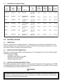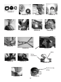
1
FRONTIER® Series
Self-Contained
Breathing Apparatus
User’s Instructions
North Safety Products
2000 Plainfield Pike
Cranston, RI 02921
USA
North Safety Products
10550 Parkway Blvd.
Anjou, Quebec
Canada H1J2K4
North Safety Products
Noordmonsterwegl
4332 Sc Middleberg
The Netherlands
Telephone 800 430-4110
Telephone 888 212-7233
Facsimile 800 572-6346
Facsimile 5140355-7233
www.northsafetyproducts.com
Telephone +31 (0) 118656400
Telephone +31 (0) 118627535
©2006 North Safety Products
Part No. 46001635 Rev. *
084112 Rev. A / A49222 Rev. A
Printed in U.S.A.
CONTENTS
1
1.1
1.1.1
1.1.2
1.1.3
1.1.4
1.1.5
1.1.6
1.2
1.3
1.4
2.0
2.1
2.2
2.3
2.4
2.5
2.6
2.7
3.0
3.1
3.2
3.3
4.0
4.1
4.2
5.0
5.1
5.1.3
5.1.4
5.2
6.0
6.1
7.0
7.1
7.2
8.0
8.1
9.0
9.1
9.2
9.2.1
9.2.2
9.3
9.4
10.0
10.1
10.2
10.3
11.0
12.0
13.0
PAGE NUMBER
INTRODUCTION
IMPORTANT INFORMATION
TERMINOLOGY
GENERAL WARNINGS
HEALTH LIMITATIONS
TRAINING PROGRAM
FIT TESTING
USER SEAL CHECKS
SERVICE DURATION
CAUTIONS AND LIMITATIONS
SPECIAL AND CRITICAL USERS’ INSTRUCTIONS
DESCRIPTION OF FRONTIER SCBA
FACEPIECE
COMPACT DEMAND VALVE (CDV)
FIRST STAGE PRESSURE REDUCER
REMOTE CYLINDER PRESSURE AND END-OF-SERVICE TIME INDICATORS
BACKFRAME AND HARNESS
CYLNDER AND VALVE ASSEMBLY
FRONTIER CYLINDER TABLE
ROUTINE CHECKS
UNPACKING
INVENTORY AND EXAMINATION
ROUTINE CHECKS AND INSPECTIONS
PUTTING ON THE RESPIRATOR AND SAFETY CHECKS
PUTTING ON THE RESPIRATOR
SAFETY CHECKS
DURING USE
NORMAL USE
INSTRUCTIONS FOR CHANGING CYLINDERS
CYLINDER BAND ADJUSTMENT
EMERGENCY EGRESS INDICATORS
AFTER USE PROCEDURES
REMOVING THE SCBA
AFTER USE CLEANING
CLEANING THE FACEPIECE AND HOOD
CLEANING THE BACKFRAME & HARNESS ASSEMBLY
SCBA STORAGE
SCBA STORAGE
USER MAINTENANCE
CYLINDER FILLING PROCEDURES
FACEPIECE DISASSEMBLY & REASSEMBLY
DISASSEMBLE FACEPIECE
REASEMBLE FACEPIECE
REPLACING FACEPIECE HEADSTRAP
BACKFRAME HARNESS
FRONTIER OPTIONS
AIRLINE
EMERGENCY AIRLINE SYSTEM (AES)
FIRST BREATH (CDV)
TROUBLE SHOOTING GUIDE
MAJOR COMPONENTS
FRONTIER WARRANTY
KEY TO CAUTIONS AND LIMITATIONS CONTAINED IN THE NIOSH APPROVAL
LABELS NIOSH APPROVAL LABEL.
2
3
3
3
4
4
5
5
5
5
6
6
8
8
9
9
9
9
9
10
10
10
10
10
12
12
13
14
14
15
15
15
16
16
16
16
17
18
18
18
18
19
19
19
20
20
20
20
21
22
22
22
23
1.0
INTRODUCTION
These instructions are for the North Frontier Series Self-Contained Breathing Apparatus, an open circuit self-contained, pressure demand, compressed air breathing apparatus. The Frontier Series was
designed to provide essential respirable air and adequate respiratory protection in both toxic and
oxygen deficient atmospheres.
The North Frontier Series respirator consists of a cylinder, backframe and harness assembly, and full
facepiece or hood.
These respirators are approved by the National Institute of Occupational Safety and Health (NIOSH).
Positive pressure is maintained within the facepiece during use, thus providing the highest degree of
respiratory protection in irrespirable atmospheres by preventing any inward leakage. The Frontier
series includes SCBA units having a NIOSH 60 minute duration, units having a NIOSH 45 minute
duration, and units having a NIOSH 30 minute duration. The North Frontier Series are also certified
by NIOSH as Pressure Demand, Type C, Supplied Air Respirators when supplied with breathing air
from a remote source, and equipped with the appropriate quick-connect couplers.
1.1
IMPORTANT INFORMATION
This Users’ Instructions contains important information and must be read and understood by all persons who may use or maintain this apparatus.
1.1.1 TERMINOLOGY
NOTE
Procedures and techniques that are considered important enough to emphasize.
CAUTION
Procedures and techniques which, if not carefully followed, will result in damage to the
equipment.
WARNING
Procedures and techniques which, if not carefully followed, will expose the user to the risk of
serious injury, illness or death.
Warnings, cautions and notes used in these instructions have the following significance:
3
WARNING
Improper Use of Your Respirator Can Be Harmful or Deadly!
For Your Safety, Read and Follow These Directives.
If You Do Not Understand Them—Ask Your Supervisor!
1. Failure to follow North’s instructions and warnings, may result in exposure to the hazardous
materials, exposing the user to the risk of serious injury, illness or death.
3.
•
•
•
•
•
•
NEVER use your respirator:
To perform or observe sand-blasting/abrasive-blasting;
To fight fires;
In temperatures below -25˚ F (-30˚ C);
Without a fully charged cylinder;
While working alone, except for escape;
When the atmospheric pressure is below 450mm (17.7 in) mercury.
4.
•
•
•
•
NEVER use your respirator if you cannot achieve a good facepiece-to-face seal due to:
Facial hair;
Eye wear that interferes with facepiece-to-face seal;
Head or face coverings that interfere with sealing area; or
Missing teeth, dentures, facial deformities or deep scars.
5.
•
•
•
•
•
IMMEDIATELY leave work area and remove respirator if:
Breathing becomes difficult;
You become dizzy or disoriented;
You no longer have a good facepiece-to-face seal;
You smell, taste or otherwise sense contaminants; or
Your respirator is damaged.
6. REMEMBER:
• Your respirator will not protect exposed areas of face or body from gases, vapors or airborne particles that can irritate, burn or be absorbed through your skin—wear hand and/or
body protection.
1.1.2 GENERAL WARNINGS
1.1.3 HEALTH LIMITATIONS
You should be certified medically fit prior to using this respirator. In addition there are both physiological and psychological limitations which should be considered before using an SCBA. They include,
but are not limited to:
a.
Emphysema
b.
Chronic obstructive pulmonary disease
c.
Bronchial asthma
d.
X-ray evidence of pneumoconiosis
e.
Evidence of reduced pulmonary function
4
f.
g.
h.
i.
j.
k.
l.
m.
n.
o.
Coronary artery disease
Severe or progressive hypertension
Neurological conditions
Anemia, pernicious
Diabetes, insipidus or mellitus
Breathing difficulty when wearing an SCBA
Claustrophobia or anxiety when wearing an SCBA
Abnormal EKG results from resting, or stress tests
Punctured or ruptured ear drum
Medications
1.1.4 TRAINING PROGRAM
These brief written instructions cannot substitute for a formal Respirator Training Program. Training
should be performed with a Safety Manager to ensure you are trained in the proper use of respirators, including putting on and removing them. Your training should include an opportunity for you to
handle the respirator, learn how to inspect it, have it properly fitted, test its facepiece-to-face seal
and wear it in an area with uncontaminated air while becoming familiar with it. You must inspect the
respirator before and after each use to ensure that it is in good working condition.
Training Programs in the U.S. should be based on ANSI Z88.2-1992, OSHA Regulation 29CFR
Section 1910.134 and other regulations promulgated by various Regulatory Authorities. In Canada,
the training program should be based on CSA Standard Z94.4-93.
1.1.5 FIT TESTING
Before you are assigned a respirator with a tight fitting facepiece, you should have a qualitative or
quantitative fit test to make sure it fits correctly. Ask your supervisor about these fit tests.
The North Frontier Series is approved with North facepieces and hoods in sizes small and
medium/large. Most faces can be fit with the medium/large; however some persons with small faces
may get a better fit with the small. In addition, if your respirator has a tight fitting facepiece, you
should be fit-tested at least once a year or any time there are changes that may affect the fit of the
respirator, such as weight changes or dental surgery.
A quantitative fit test adapter (North catalog number 900099) is available for conducting fit tests.
Instructions for fit testing are given in OSHA 29 CFR §1910.134 Appendix A, and respirator manuals
published by government agencies such as NIOSH, ERDA, and NRC.
1.1.6 USER SEAL CHECKS
Each time that the respirator is put on, and before each entry into a contaminated atmosphere, the
respirator wearer should check the effectiveness of the seal of the facepiece to the wearer’s face by
carrying out a user seal check. Instructions for carrying out user seal checks on this respirator are
given in Section 4.2.1 of these User’s Instructions.
1.2
SERVICE DURATION
The Frontier has been approved as a 30 minute, 45 minute or 60 minute breathing apparatus. The
useful service duration of this, or any SCBA, will depend on the user’s varying work rate, physical
condition and other factors which could substantially shorten the actual duration of the unit.
5
WARNING
The useful service duration of your SCBA will frequently be less than the rated service duration
depending on any of the factors listed below. In any event, when the respirator’s low air warning
whistle sounds it means the air cylinder is running out of air and you must PROCEED IMMEDIATELY TO A SAFE AREA. Failure to proceed to a safe area when the alarm sounds will result in
the risk of exhausting the supply of breathable air while in the hazardous area, and exposing you
to illness, injury or death.
1.3
CAUTION AND LIMITATIONS
CAUTION
D - Airline respirators can be used only when the respirators are supplied with respirable air
meeting the requirements of CGA G-7.1 Grade D or higher quality. Use only the pressure
ranges and hose lengths specified in the User’s Instructions.
E - Use only pressure ranges and hose lengths specified in the User's Instructions
J - Failure to properly use and maintain this product could result in injury or death.
M - All approved respirators shall be selected, fitted, used, and maintained in accordance with
OSHA and other applicable regulations.
N - Never substitute, modify, add, or omit parts. Use only exact replacement parts in the
configuration as specified by the manufacturer.
O - Refer to User’s Instructions and/or maintenance manuals for information on use and
maintenance of these respirators.
S - Special or critical User’s Instructions and/or specific use limitations apply. Refer to User’s
Instructions before donning.
1.4
SPECIAL AND CRITICAL USERS’ INSTRUCTIONS
WARNING
•
•
•
•
•
•
•
•
Approved for respiratory protection during entry into or escape from oxygen deficient
atmospheres, gases and vapors at temperatures above -25°F when using the standard face
mask or urethane (blue) AirHood.
Approved for respiratory protection during entry into or escape from oxygen deficient
atmospheres, gases and vapors at temperatures above 20°F when using the vinyl (clear)
AirHood.
Approved only when compressed gas container is charged with air meeting the requirements
of CGA G-7.1 Grade D or higher quality that has a dew point of -65°F or lower and a
maximum particulate level of 5 mg/m air.
The compressed gas container shall meet applicable DOT specifications.
When used as a combination apparatus, only 20% of the service pressure may be used on
entry.
This approval applies only when the device is supplied with respirable breathing air through
6 to 300 feet of hose at air pressures between 80 to 120 pounds per square inch gauge or
from self contained air supply.
If the supplied air fails, open the cylinder valve and proceed to fresh air immediately.
Use adequate skin protection when worn in gases and vapors that poison by absorption
(example: hydrocyanic-acid gas).
6
WARNING
When using this unit as a Type C Supplied Air Respirator
DO NOT
•
Use any supply hose longer than 300 feet
•
Use more than 12 sections of supply hose in any combination.
•
Use other than North air supply hose approved for use with this unit, or
•
Use a quick-connect coupler at the air source without compensating for the pressure drop
by increasing the required pressure at least 1 and no more than 5 psig.
Each of these prohibited hose configurations will reduce air flow to the facepiece below the
required minimum, exposing the user to risk of serious injury, illness or death.
Be sure that all respirable air system piping, tubing, fittings and couplings are incompatible with
non-respirable gas systems. OSHA Regulation 29 CFR 1910.134, “Respiratory Protection” states
“Airline couplings shall be incompatible with outlets for other gas systems to prevent inadvertent
servicing of air line respirators with non-respirable gases or oxygen.
WARNING
The air supply must have the capacity to maintain the required pressure during respirator use.
DO NOT USE COMPRESSED OXYGEN IN THIS RESPIRATOR.
The air supply source must be constructed and situated so as to avoid entry of contaminated air
into the system. Suitable in-line filters must be installed to assure breathing air quality. If using an
oil-lubricated compressor, it must be equipped with either a high temperature alarm or a carbon
monoxide alarm, or both. If only a high temperature alarm is used, the air from the compressor
must be frequently tested, (as outlined in the OSHA Regulation 29 CFR 1910.134), for the presence of carbon monoxide to ensure that the air conforms to specification requirements for
breathing air.
WARNING
If the supplied air fails, open the cylinder valve and proceed to fresh air immediately,
7
CAUTION
Do not expose the respirator to excessive heat (above 140°F / 60°C), moisture, or contaminating
substances during storage. Excessive heat may distort the facepiece or hood, and their components, resulting in the inability to achieve a proper fit. Moisture and contaminated air can damage the demand and exhalation valves. Either of these conditions will expose you to the risk of
serious injury, illness or death.
NOTE
MANUAL BYPASS: The FRONTIER has a manually operated bypass which provides a continuous
flow of air to the facepiece or hood when required, independent of normal operation of the regulator. The bypass is opened by turning the red knob on the Compact Demand Valve 90 degrees.
2.0
DESCRIPTION OF FRONTIER SCBA
The North FRONTIER is a self-contained, open-circuit, compressed-air breathing apparatus that is
approved by the National Institute of Occupational Safety and Health (NIOSH). (Figure 1)
Positive pressure is maintained within the facepiece during use, thus providing the highest degree of
respiratory protection in irrespirable atmospheres by preventing any inward leakage.
The FRONTIER consists of several major components described in the following paragraphs:
2.1
FACEPIECE OR HOOD
The North facepiece assembly has a four-point adjustable head harness. The facepiece standard
seal has a blended shape to ensure a proper fit. A standard inner-mask oral/nasal cup reduces
dead-air space and CO2 buildup. (Figure 2)
The North AirHood is also available for users that prefer to wear their own eyeglasses or may have
facial hair that may interfere with the sealing surface. The sealing surface of the hood is around the
neck, and there may not be any hair or jewelry interfering with the neck seal. The North AirHood is
NIOSH approved for entry into an IDLH atmosphere. The AirHood has a hard visor with a permanent
anti-fog coating that offers excellent vision, an inner oral/nasal cup to reduce CO2 build-up, and
adjustable side straps for a comfortable fit. The AirHood is available in two sizes to comfortably fit
any person. (Figure 2)
The AirHood facepiece is made of several components, each having different reactions to chemical
environments. It is vital to ensure that you have objective evidence that the hood will be able to
maintain its integrity against the expected chemical exposure during operations. This can be accomplished by tests you conduct or by contacting North for further information. Listed below are a few,
but not necessarily all chemicals that are known to work well with the AirHood's material:
Urethane (blue)
Alcohols
Fuels
Mineral oils
Greases, oils
Vinyl (clear)
Weak acids
Strong alkali solution
Organic acids
8
2.2
COMPACT DEMAND VALVE (CDV)
The patented Compact Demand Valve regulator combines high flow with a low profile to improve
mobility (Figure 3). The CDV exhalation valve greatly reduces breathing resistance which allows for
longer duration of cylinder use. The CDV is easily docked into the facepiece using a threaded hand
wheel. An optional first breath CDV is also available.
2.3
FIRST STAGE PRESSURE REDUCER
Air leaves the cylinder, passes through a sintered bronze filter in the hand wheel assembly, and then
continues on to the first-stage pressure reducer where it is reduced to approximately 125 psi. The
reducer is a simple piston type that requires no adjustment and incorporates an automatic, self-seating pressure relief valve to protect the downstream low-pressure components (Figure 4). It is made
of high quality aluminum, and is securely mounted to the cylinder.
2.4
REMOTE CYLINDER PRESSURE AND END-OF-SERVICE TIME INDICATORS
The remote pressure gauge and whistle assembly is chest mounted on the right shoulder strap. The
pressure gauge is waterproof with a neoprene protective cover and features a luminous dial and
pointer markings. The gauge display shows the fraction of cylinder pressure remaining.
The primary End-of-Service-Time indicator is a whistle which is set to sound at 23%-27% of rated
cylinder pressure per NIOSH requirements.
2.5
BACKFRAME AND HARNESS
The backframe and harness assembly utilize ergonomic design principles to produce a comfortable,
low profile unit that evenly distributes the SCBA weight between the wearer’s hips and shoulders
(Figure 5).
A quick-release cylinder band fits a wide range of cylinders with an infinitely adjustable strap to
ensure a tight fitting cylinder.
The harness material is a custom woven Nylon with easy slide shoulder buckles allowing for quick
donning of the Frontier SCBA. Optional Kevlar straps and shoulder pads are also available.
2.6
CYLINDER AND VALVE ASSEMBLY
A range of cylinder types and capacities are accommodated on the FRONTIER 2216 psi and 4500
psi models. (Please refer the table in Section 2.7 for specifics.)
The cylinder valve is of forged aluminum construction with a permanent Teflon coating. The valve
outlet is a standard CGA-346 fitting on 2216 psi cylinders, and a standard CGA-347 fitting on 4500
psi cylinders. Each valve has a frangible disc safety relief device, and a dual-reading pressure
gauge. Valve protection is provided by an elastomeric bumper.
CAUTION
Never lift or carry the unit by the facepiece or gauge assembly. If a hose becomes kinked or otherwise damaged, it should be replaced. Check for damage next to the metal ends of the hose.
9
2.7
FRONTIER CYLINDER TABLE
Part
Number
North
Catalog
Number
Pressure
PSIG
024.037.00
910301LP
2216
Aluminum
1287 liters
45 cu. ft.
024.035.00
910302LP
2216
Hoop Wrapped
Aluminum
1301 liters
45.5 cu. ft.
Material
Free
Air
Capacity
NIOSH
Rated
Duration
@ 40 lpm
Cylinder
& Valve
Charged
Weight
30 min.
20.5 lbs.
6.9 in.
5 years
30 min.
16.0. lbs.
6.9 in.
3 years
Cylinder Hydrostatic
Diameter
Interval
124001
910303LP
2216
Full Wrapped
Carbon
1301 liters
45.5 cu. ft.
30 min.
10.4 lbs.
6.9 in.
5 years
024.098.00
910302HP
4500
Hoop Wrapped
Aluminum
1287 liters
45 cu. ft.
30 min.
15.9 lbs.
5.5 in.
3 years
124002
910303HP
4500
Full Wrapped
Carbon
1287 liters
45 cu. ft.
30 min.
11.0 lbs.
5.4 in.
5 years
124003
910453HP
4500
Full Wrapped
Carbon
1887 liters
66 cu. ft.
45 min.
14.8 lbs.
6.8 in.
5 years
124004
910603HP
4500
Full Wrapped
Carbon
2516 liters
88 cu. ft.
60 min.
19.2 lbs.
7.1 in.
5 years
3.0
ROUTINE CHECKS
3.1
UNPACKING
Open the storage case or shipping container. Observe the relative position and placement of the
various components for future re-packing. Remove SCBA from the container and place on a clean
dry surface. Remove facepiece from protective bag.
3.2
INVENTORY AND EXAMINATION
Examine unit for physical condition and appearance of all components. Be sure the following major
components are included:
•
Facepiece or Hood
•
Backframe and Harness Assembly
•
Cylinder and Valve Assembly
•
Options ordered with unit
3.3
ROUTINE CHECKS AND INSPECTIONS
The following procedure shall be used for incoming and daily inspection of the apparatus. An SCBA
not routinely used, but kept for emergency use, shall be inspected at least monthly. All other apparatus shall additionally be inspected after each use.
WARNING
The apparatus must not be used until the following tests have been successfully completed. Any
discrepancy noted during the pre-use check and inspection shall be corrected only by authorized
personnel prior to the use of the apparatus.
10
3.3.1 Visually inspect complete apparatus for worn or aged parts and damaged components.
3.3.2 Basic cylinder inspection shall include:
A. Inspect gauge for damage.
B. Inspect cylinder for mechanical damage (cracks, dents, gouges) or signs of heat or
chemical damage. (Refer to CGA C-6.2 "Guideline for Visual Inspection and
Requalification of Fiber Reinforced High Pressure Cylinders" for all wrapped cylinders.)
C. Check that hydrostatic test date on cylinder is current.
D. Check that cylinder valve threads are not damaged.
E. Check that the valve body is not bent.
F. Check that the burst disc outlet is clean and free of debris.
G. If any item listed above is noted, depressurize cylinder to a slight positive pressure,
tag, and take out of service.
3.3.3 Connect the CDV to the FRONTIER facepiece or hood by screwing the CDV hand wheel into
the hood or facepiece. Make sure the manual red bypass knob is in the closed position, i.e., fully
turned clockwise.
3.3.4 Open the cylinder valve slowly by turning the cylinder valve knob counter-clockwise to the
fully open position. Hold facepiece tight to your face. The whistle alarm should activate and then shut
off. There should be no air flow from the facepiece. If air is flowing, check that bypass is closed. For
the First Breath CDV, inhale to activate air flow.
3.3.5 CHECK CYLINDER PRESSURE:
Remote cylinder pressure gauge should read above 90% of maximum rated pressure. If the
cylinder pressure reads 90% or less, refill or replace with a fully charged cylinder (Figure 6).
WARNING
Ensure that only a 2216 psi cylinder is used with low pressure pneumatics and a 4500 psi cylinder
is used with high pressure pneumatics.
3.3.6 POSITIVE PRESSURE CHECK FOR FACEPIECE:
While holding the facepiece tight to your face, insert two fingers between the facepiece and face.
Gently lift the seal away from the face and ensure a good outward flow of air (Figure 7). Reseal the
facepiece and hold your breath for three seconds. There should be no sound of air flowing. Open the
optional bypass knob and check for a constant air flow. Close bypass knob.
3.3.7 POSITIVE PRESSURE CHECK FOR HOOD:
insert two fingers between the seal and neck. Gently lift the seal away from the neck while pulling
the oral/nasal cup away from the face (Figure 8). A good outward flow of air should be felt. Reseal
the hood and stop breathing for three seconds. There should be no sound of air leaking from the
CDV. Open the bypass knob and check for a constant flow. Close the bypass knob.
3.3.8 LOW PRESSURE ALARM TEST:
Close cylinder valve and gradually reduce the pneumatics by opening the bypass to slowly vent the
air. Check to see that the whistle "End-of-Service" alarm activates as the needle enters the red section of the gauge (1/4 marking) (Figure 15).
11
3.3.9 LEAK TEST OF SCBA:
Remove the CDV from the SCBA by unscrewing the CDV from the facepiece or hood. To do this turn
the CDV counterclockwise and pull it out of the facepiece or hood. On the First Breath CDV, push
button "in" prior to removal. With the CDV disconnected from the facepiece or hood, open the cylinder valve and place the test cap over the CDV outlet port. Do not seal with test cap until air flow has
begun. Allow the pneumatics to pressurize and then close cylinder valve. Lightly place a finger over
the hole in the test cap to restrict air flow. The needle on the pressure gauge should not fall more
than 1/8 inch per minute. Remove the test cap to drain pneumatics.
NOTE
The CDV flows a very small amount of air past the pilot jet. The test cap has a small hole to allow
the air to escape. It may be necessary to hold the test cap in place while performing the leak test.
3.3.10 Connect CDV to the facepiece or hood. Pull gently outward on the CDV to ensure it is
docked properly.
3.3.11 Return apparatus to storage, or proceed to donning instructions.
IMPORTANT
Complete all routine checks and inspection procedures outlined in Section 3 before starting donning procedures provided in Section 4.
WARNING
If any of the tests listed above fail, remove the apparatus from service, tag and return for repair
by authorized personnel.
NOTE
After every 100 hours of use, or at least once per year, the entire SCBA should be taken out of
service and tagged for comprehensive maintenance by an authorized, trained technician.
4.0
DONNING PROCEDURES AND SAFETY CHECKS
4.1
DONNING PROCEDURES
4.1.1 Position the Frontier on the ground with the cylinder valve facing towards you (Figure 9).
4.1.2 Spread the shoulder straps apart. Ensure all strap assemblies, side and waist, are fully
extended and waist belt buckle assembly is not connected.
4.1.3 Grasp the left shoulder strap with your left hand. Lift the FRONTIER onto your left shoulder.
Place your right arm through the right shoulder strap (Figure 10).
4.1.4 Pull directly down on the shoulder straps to adjust position of unit on back (Figure 11).
4.1.5 Connect the waist belt buckle and adjust waist belt to a comfortable snug fit. Tuck the excess
waist belt and shoulder strap pull-downs inside the waist belt (Figure 12).
12
4.1.6 Attach the CDV into the facepiece or hood (Figures 13 and 14).
4.1.7 Rotate and pull outward to ensure CDV is not cross threaded into the facepiece or hood.
4.1.8 Open cylinder valve slowly by turning counter-clockwise to the full open position. The whistle
should activate when opening the cylinder valve. Air should be flowing out of the CDV.
4.1.9 TO PUT FACEPIECE ON:
Adjust the headstrap by pulling back on the lower straps first before adjusting the top straps. On
CDV's with First Breath, inhale to activate airflow.
TO PUT HOOD ON: Place your hands inside the neck seal opening and spread apart. Do not use
your fingertips to spread neck seal apart as the fingernails may puncture the seal. Also note, sharp
rings can tear the neck seal. Place your chin into the opening and pull the hood over your head.
Adjust the oral/nasal cup over your mouth and nose and tighten the side straps by pulling forward.
Ensure the neck seal lays flush against your neck and that no hair or other items pass between you
and neck seal. On CDV's with first breath, inhale to begin airflow.
NOTE
For hoods equipped with a First Breath CDV it is necessary to push the hood slightly towards your
face (sealing the oral/nasal cup against your face) before your first inhaled breath. A quick rush of
air should be heard when airflow is activated.
4.1.10
The whistle will shut off once a seal is achieved.
CAUTION
Do not over tighten the facepiece. Doing so may cause discomfort, facepiece deformation and
leakage.
4.2
SAFETY CHECKS
WARNING
These safety checks MUST be performed before entering a hazardous area. Failure to perform
these checks may result in respiratory injury or death.
4.2.1 POSITIVE PRESSURE USER SEAL CHECK:
With cylinder valve open, breathe normally. Insert two fingers between your facepiece and face.
Gently lift the facepiece seal away from your face and ensure a good outward flow of air, showing
that the facepiece pressure is positive. Reseal facepiece and hold your breath for 3 seconds. There
should be no sound of air leaking, and you should not sense any airflow in the eye region of the
mask.
13
NOTE
It is not necessary to perform a negative pressure user’s seal check because the CDV, facepiece
and hood are designed as positive pressure assemblies.
4.2.2 ALARM CHECK:
Close the cylinder valve and continue to breathe normally. Monitor pressure gauge and listen for the
whistle to activate as the gauge needle enters into the red zone (Figure 15). Open cylinder valve
fully.
4.2.3 Take two to three deep breaths to ensure you are getting adequate air into the facepiece. The
facepiece should not move towards your face.
4.2.4 BYPASS CHECK:
The red bypass knob is located on the right side of the CDV. Turn the bypass knob clockwise to
open the bypass valve. A constant flow of air should pass into the facepiece. Turn the knob in the
opposite direction to turn the bypass valve off.
4.2.5 RE-CHECK CYLINDER PRESSURE
Check the pressure gauge on the right shoulder harness. The gauge should read above 90% full
(more than halfway between 3/4 and full). Breathe normally and proceed as planned.
WARNING
If any of the safety checks noted above fail, DO NOT PROCEED. Remove the apparatus from
service, tag and return it for repair by authorized personnel.
Use of the optional bypass in non-emergency situations will substantially reduce the duration of
the apparatus.
The bypass will not function if the cylinder is out of air.
CAUTION
The user should have received training on how to handle a possible emergency before entering
a hazardous area.
5.0
DURING USE
5.1
NORMAL USE
5.1.1 Monitor cylinder pressure during use for remaining air supply and allow sufficient time to exit
the contaminated area.
5.1.2 The End-of-Service-Time indicator (whistle alarm) activates when the there is approximately
25% of the air supply from a full cylinder remaining. Exit when alarm activates.
14
WARNING
25% OF A FULL CYLINDER MAY BE INSUFFICIENT IN SOME CIRCUMSTANCES TO SAFELY
EXIT FROM AN IDLH ATMOSPHERE
One example would be a long-distance egress through a continuous IDLH (Immediately
Dangerous to Life or Health) atmosphere. In such situations, begin exiting prior to activation of
the End-of-Service-Time indicator
5.1.3 INSTRUCTIONS FOR CHANGING CYLINDERS
5.1.3.1
Make sure cylinder valve is closed and all air is released from the pneumatic system.
5.1.3.2
Pull the center of the locking latch outward to relieve cylinder band tension (Figure 16).
5.1.3.3 Disconnect the hand wheel from cylinder valve and remove cylinder by sliding cylinder
upward through cylinder band (Figure 17).
5.1.3.4 Insert new full cylinder by sliding down through cylinder band until cylinder rests against
bottom retainer (Figure 18).
5.1.3.5 Connect the hand wheel to cylinder valve and position cylinder.
5.1.3.6 Close the locking latch.
5.1.4
CYLINDER BAND ADJUSTMENT
5.1.4.1 Make sure cylinder valve is closed and air is released from the pneumatic system.
5.1.4.2 Pull outward on latch to relieve cylinder band tension (Figure 16).
5.1.4.3 To loosen the cylinder band, slide the outer cylinder band strap towards the locking latch
and pull the inner strap to enlarge strap opening (Figure 19).
To tighten the cylinder band, grab the outer cylinder band strap and pull up/away from the adjustment latch. Slide the slack across the inner strap (Figure 20). Slide the slack away from the latch,
across the cylinder. Do not over tighten the strap.
5.1.4.4 Connect the hand wheel to cylinder valve and position cylinder.
5.1.4.5 Close the locking latch.
5.2
EMERGENCY EXIT INDICATORS
If any of the
A.
B.
C.
following situations occur, immediately exit the contaminated area:
Harness failure
Chattering or unusual noises from SCBA
Submersion in water (Note: In this situation the FRONTIER will continue to supply air
on demand to a depth of at least 9.8 feet (3 meters)
15
D.
E.
F.
G.
6.0
SCBA is subjected to any high impact such as a fall
Air flow decreases so that the facepiece moves inward toward the face during
inhalation (Note: In this situation, open bypass to provide extra, constant flow.)
Air flows constantly at a high rate (Note: In this situation, adjust the flow rate by slowly
closing the cylinder valve until a comfortable flow rate is established. The flow rate
should match the bypass flow rate during normal operation.)
Exposure to unknown gases or chemicals that may require the use of a Class "A" suit.
AFTER USE PROCEDURES
CAUTION
Do not remove any equipment until you are completely clear of an Immediately Dangerous to
Life and Health (IDLH) atmosphere.
6.1
REMOVING THE SCBA
6.1.1 Loosen head straps fully. Air should start to free flow from the facepiece or hood. Take a deep
breath.
6.1.2 Close the cylinder valve by turning it fully clockwise.
6.1.3 TO REMOVE THE FACEPIECE: On CDV with First Breath, push button "in" and remove the
facepiece.
6.1.4 TO REMOVE THE HOOD: Place both hands under the neck seal and lift hood over the front
of your face.
6.1.5 Unfasten the waist belt and loosen shoulder straps. Extend shoulder straps and waist belt
fully.
6.1.6 Remove the apparatus.
6.1.7 Remove the cylinder and tag it for refilling. Refer to Section 9 for instructions.
6.1.8 Do not store or place apparatus in ready position until all steps in Section 7, “After Use
Cleaning”, are performed.
CAUTION
To avoid damage to the lens, do not place the facepiece or hood down on rough surfaces.
7.0
AFTER USE CLEANING
7.1
CLEANING THE FACEPIECE
16
7.1.1 Disconnect the CDV from the facepiece or hood by turning the hand wheel on the CDV counterclockwise and then remove the CDV (Figure 21). Wash the facepiece or hood in cool to warm
soapy water for no more than 10 minutes. Use a mild, non-detergent, dishwashing soap (e.g. Ivory).
CAUTION
Do not put the CDV under running water or submerge under water.
7.1.2 Rinse the facepiece or hood thoroughly in clean running water, allowing the water to flow
through the facepiece or hood.
7.1.3 After rinsing, shake to remove excess water. Wipe dry with a soft, clean cloth.
CAUTION
When further cleaning due to heavy contamination is required, clean with North recommended
Disinfectant/Cleaner (North catalog number 80992) after rinsing the facepiece or hood. Use of
other disinfectants may cause damage to SCBA components. Consult with North Customer
Service if you have any questions.
7.1.4 Ensure all head harness straps are fully extended, ready for use.
WARNING
If the apparatus is likely to be stored temperatures below freezing, 32˚F (0˚C), the facepiece or
hood must be dried thoroughly prior to storage.
7.2
CLEANING THE BACKFRAME AND HARNESS ASSEMBLY
7.2.1 Fully extend shoulder straps and waist belt to full open position. Clean off any dirt with a
medium bristle brush or sponge and a mild, non-detergent dishwashing soap. DO NOT USE
BLEACH OR ANY COMPOUND CONTAINING CHLORINE AS THIS WILL TEND TO RAPIDLY
DETERIORATE FABRIC.
CAUTION
If it is necessary to clean the exterior of the CDV, care should be taken to ensure no trace
amounts of water are left in the CDV opening. Connect the unit to a full cylinder and blow any
water out, particularly if the apparatus is to be used or stored at temperatures below freezing.
WARNING
Do not immerse pneumatics in water.
Perform all testing and maintenance work in a clean environment
17
8.0
SCBA STORAGE
8.1
SCBA STORAGE
8.1.1 Complete routine checks and inspection procedures outlined in Section 3.3 of these User’s
Instructions.
8.1.2 Ensure that complete apparatus is clean and dry.
8.1.3 Ensure that the bypass knob is in the CLOSED position.
8.1.4 Ensure that the head harness straps are fully extended on the facepiece. Connect CDV into
the facepiece or hood assembly and store in case, positioned to avoid distortion.
8.1.5 Ensure that shoulder and waist belt straps are fully extended.
8.1.6 Place the complete apparatus in the storage case or suitable storage place so it can be easily
reached for emergency use.
8.1.7 MOUNTING SCBA: When storing SCBA using mounting brackets, ensure that brackets are
secure and that no sharp objects will come in contact with SCBA or cylinder.
8.1.8 If you have the First Breath CDV, push button "in" to set first breath.
9.0
USER MAINTENANCE
9.1
CYLINDER FILLING PROCEDURES
9.1.1 Basic cylinder inspection shall include:
A.
Inspect gauge for damage.
B.
Inspect cylinder for mechanical damage (cracks, dents, gouges) or signs of heat or
chemical damage. (Refer to CGA C-6.2 "Guideline for Visual Inspection and
Requalification of Fiber Reinforced High Pressure Cylinders" for all wrapped cylinders.)
C.
Check that hydrostatic test date on cylinder is current.
D.
Check that cylinder valve threads are not damaged.
E.
Check that the valve body is not bent.
F.
Check that the burst disc outlet is clean and free of debris.
G.
If any item listed above is noted, depressurize the cylinder to a slight positive pressure,
tag, and take out of service.
CAUTION
Cylinders that are tagged for repair should always be stored empty with the cylinder valve closed
to prevent contamination or condensation inside the cylinder.
9.1.2 Prior to filling the cylinder, follow the basic inspection procedures outlined in 9.1.1
9.1.3 Cylinder air shall meet or exceed the standards in CGA G 7.1 Grade D or higher.
18
9.1.4 Fill cylinder to the maximum rated pressure (FULL). Wait at least 30 minutes to allow cylinder
to cool to room temperature, then add extra air to return the cylinder gauge to full. Note: the
pressure will drop as cylinder temperature drops.
9.2
FACEPIECE DISASSEMBLY AND REASSEMBLY
Tools required: #2 Phillips screwdriver, 2 pin spanner
9.2.1 TO DISASSEMBLE:
9.2.1.1 Remove the two screws from the lens clamps (Figure 22). The nuts may fall out of the
lower clamp. Carefully pry the clamps apart and remove from the lens.
9.2.1.2 Remove lens from the facepiece seal (Figure 23).
9.2.1.3 Remove inner oral/nasal cup. Lift up slightly and pull away from the exhalation assembly
(Figure 24).
9.2.1.4 Rotate the exhalation valve assembly clockwise until the slots align with the grove in the lens
(Figure 25). Push the exhalation valve assembly outward.
9.2.1.5 Remove the CDV adapter using the two pin spanner tool by placing the spanner tool on the
retaining nut and turning counter clockwise (Figure 26). Remove nut and CDV adapter, and
gently remove the CDV seal from the lens (Figure 27).
9.2.2 TO REASSEMBLE:
9.2.2.1 Gently install the CDV seal into lens, ensuring the seal is flat against the lens on both sides
(Figure 28). The seal needs to be orientated so that one detent points to the oral/nasal cup.
Install outer CDV connector through the seal and attach retainer nut from inside the mask
(Figure 29).
9.2.2.2 Tighten retainer nut using spanner tool until making contact with the seal (Figure 30). Turn
1/4 to 1/2 turn more using the spanner tool. Check the outside connector is tight by trying to
rotate connector. If loose, tighten retainer nut slightly and recheck.
9.2.2.3 Install exhalation valve assembly: There are three notches, one notch is
rectangular and the other two are curved. Place the rectangular notch in the upper left-hand
corner of the lens. Rotate the exhalation assembly from the inside of the visor counter
clockwise until the assembly locks in-place (Figure 31).
CAUTION
Do not rotate exhalation valve assembly by the outside cover.
9.2.2.4 Install oral/nasal cup: Install the oral/nasal cup over the first groove of the
exhalation valve assembly (Figure 32). Start at the bottom and gently seat the oral/nasal
cup. There are two notches in the oral/nasal cup, one at the top and one at the bottom.
Rotate slightly to align the notches to seat the oral/nasal cup properly.
19
9.2.2.5 Install facepiece seal: Install the lens into the facepiece seal (Figure 33). Gently
work the lens into the face seal. Ensure the visor is positioned so the facepiece is not
distorted. Place a small amount of liquid soap around the attaching area of the lens clamp.
Install the visor clamps and tighten screws.
9.3
REPLACING FACEPIECE HEADSTRAP
NOTE
It is helpful to have a second assembled facepiece for reference during reassembly.
9.3.1 The harness assembly is a four point harness. Remove harness assembly by pushing forward
at each attachment point to align the button with the groove and remove the harness from
facepiece (Figure 34). Repeat at each attachment point.
9.3.2 To remove the headstrap from the buckle (latch and bail assembly), gently work the pull tab of
the headstrap through the bail (Figure 35).
9.3.3 Orientate the new headstrap so the large opening is aligned near the chin opening of the
facepiece (Figure 36).
9.3.4 To reinstall, ensure the bail is placed on the inside of the latch and feed the pull tab end of the
headstrap through the buckle. The end of the pull tab should facing outward and the ribs
should engage the buckle. Repeat on the other three sides. Reinstall harness assembly to
facepiece, locking the buttons into the grooves of the buckle.
9.4
BACKFRAME HARNESS
NOTE
It is helpful to have a second assembled backframe for reference during reassembly.
9.4.1 Separate lower strap from upper shoulder strap.
9.4.2 The upper shoulder straps terminate in a “Z“ pattern (Figure 37). Pull one inch of slack
through the backframe (Figure 38), fold the end of the strap tight against the strap and pass
the end through the backframe. Repeat on other strap.
9.4.3 Remove waist belt strap in the same manner. Pull one inch of slack and pass the strap
through the pathway of the strap (Figure 39). Observe the path prior to removal.
9.4.4 Reverse the steps to reinstall.
10.0 FRONTIER OPTIONS
10.1
AIRLINE
10.1.1 The Airline Attachment is located on the left waist belt strap (Figure 40). It is approved with
Foster, Hansen HK, and Schrader couplings. Foster, Hansen HK, and Schrader couplings
include locking devices.
20
10.1.2 When using supplied air, the user must ensure that the cylinder valve is closed. Failure to do
so may result in reduced cylinder duration.
10.1.3 Airline respirators can be used only when the respirators are supplied with respirable air
meeting the requirements of CGA G-7.1 Grade D or higher quality.
10.1.4 When used as a combination apparatus, only 20% of the service pressure may be used on
entry.
10.1.5 This approval applies only when the device is supplied with respirable breathing air through 6
to 300 feet of hose at air pressures between 80 to 120 psi from a suitable compressed air
source.
10.1.6 Follow Donning Procedures located in Section 4.0 and Safety Checks in Section 4.2.
10.1.7 Plug airline hose from Frontier into supplied airline hose. Supplied air pressure shall be
between 80 to 120 psi. Close cylinder valve and continue to breathe normally. If supplied air
is interrupted, open cylinder valve fully, unplug airline hose and then exit to a safe area.
NOTE
Care must be taken to avoid pulling on the supplied air hose. Doing so may cause hose stress or
failure.
10.1.8 Take necessary actions to monitor the supplied air source pressure while operating with
supplied air.
10.1.9 To transfer from supplied air to cylinder air, open cylinder valve first. Disconnect supplied air
hose by retracting coupling sleeve.
10.2
EMERGENCY AIRLINE SYSTEM (EAS)
10.2.1 The NORTH Frontier EAS can be ordered with or without an airline attachment and is
attached to the left waist strap (Figure 40). The EAS socket will have a dust cover that must
be removed prior to use.
10.2.2 To disconnect the facepiece hose, hold the socket in one hand and push in on the male plug
(Figure 41). Then pull back on the socket sleeve to release. Remove dust cover from the
other Frontier, and firmly push facepiece hose into socket. Air will start flowing into the
facepiece.
10.2.3 After establishing airflow, immediately exit to a safe area.
NOTE
It is essential that individuals practice this procedure in a non-IDLH atmosphere prior to using the
EAS option. To simulate having an empty cylinder, close the cylinder, take a deep breath to deplete
the pneumatic pressure, then unplug the facepiece hose and plug into another Frontier EAS
attached to the left waist strap.
21
10.2.4 Although the EAS is a NIOSH approved accessory, NIOSH does not approve the use of an
EAS device. Use of the EAS voids NIOSH approval while being used.
10.3
FIRST BREATH CDV
10.3.1 The CDV with First Breath allows the user to save air. Open the cylinder valve and don the
facepiece. Activate the CDV by inhaling (taking a normal breath) and the button will release,
starting the flow of air. Prior to removing the SCBA, simply press the button inward and the
airflow will stop (Figure 42).
NOTE
If using the AirHood with a First Breath CDV, after donning immediately push the seal of the
oral/nasal cup to the face and inhale in order to activate the first breath. A quick rush of air will be
heard when airflow is activated.
11.0 TROUBLE SHOOTING GUIDE
PROBLEM
POSSIBLE CAUSE
Cylinder valve is not open
No air in the cylinder
CORRECTION
No air flow inside the facepiece
1.
2.
1.
2.
Open the cylinder valve
Fill the cylinder
Low air flow inside the facepiece
Cylinder valve is only slightly open
Open cylinder valve several turns
Air free flows in facepiece at all times
The Bypass is open
Close the Bypass
Air leakage is heard when exhaling
The Bypass is slightly open
Close the Bypass fully
12.0 MAJOR COMPONENTS
12.1 Full Facepiece Assemblies
North Catalog Number Description
903010
Complete Facepiece Assembly, Medium/Large
903010S
Complete Facepiece Assembly, Small
904010
Complete AirHood Assembly, Polyurethane, Large/ X Large
904010S
Complete AirHood Assembly, Polyurethane, Small/Medium
905010
Complete AirHood Assembly, PVC, Large/ X Large
905010S
Complete AirHood Assembly, PVC, Small/ Medium
12.2 Cylinders
North Catalog Number
910301LP
910302LP
910303LP
910302HP
Description
30 minute, Replacement
30 minute, Replacement
Aluminum, 2216 psi
30 minute, Replacement
2216 psi
30 minute, Replacement
Aluminum, 4500 psi
22
Cylinder, Aluminum, 2216 psi
Cylinder, Hoop Wrapped
Cylinder, Full Wrapped Carbon,
Cylinder, Hoop Wrapped
910303HP
910453HP
910603HP
30 minute, Replacement Cylinder, Full Wrapped Carbon, 4500 psi
45 minute, Replacement Cylinder, Full Wrapped Carbon, 4500 psi
60 minute, Replacement Cylinder, Full Wrapped Carbon, 4500 psi
12.3
Backframe & Harness Assembly
North Catalog Number
Description
900020
Backframe Harness Assembly, Low Pressure, Nylon Straps
900020K
Backframe Harness Assembly, Low Pressure, Kevlar Straps
900020
Backframe Harness Assembly, High Pressure, Nylon Straps
900020K
Backframe Harness Assembly, High Pressure, Kevlar Straps
FRONTIER WARRANTY
North Safety Products warrants the FRONTIER SCBA to the original owner to be free from defects in
materials and workmanship for a period of three (3) years from the date of original shipment from
North’s factory. North’s obligation under this warranty will be, at North’s option, to repair or replace
without charge the apparatus or any of its components found by North to have been defective during
the warranty period, under the following terms:
2.
The warranty claim is made (i) by the owner who purchased the apparatus new from
North or an authorized North Distributor, as shown on the completed Warranty &
Registration Card returned to North; and (ii) not more than three (3) months after the
end of the warranty period.
3.
The apparatus or component is found by North to have been defective in normal use
and service during the warranty period of three (3) years from the date of purchase by
the owner.
4.
The apparatus or component is returned freight prepaid to North, either to its factory in
Cranston, Rhode Island, or to a North authorized service center, and is thereafter
returned to the owner freight collect.
5.
This warranty does not apply (i) to any apparatus or component found by North to have
become defective as a result of any accident, alteration, misuse, abuse, or servicing
with parts not approved by North; or (ii) to deterioration or aging of any component
made of rubber or other elastomer since they can be adversely affected by undue
exposure to heat, sun, water, chemicals, ozone or other deteriorative elements; (iii)
facepiece lens, compressed-air cylinders and parts that become defective through
normal use.
The decision as to what constitutes normal use shall be made solely by NORTH.
6.
To maintain this warranty, the purchaser must perform maintenance and inspections as
prescribed in the User’s Instructions which shall include prompt replacement or repair
of defective parts, and replacement of parts per the maintenance schedule as
prescribed in the User’s Instructions.
7.
To validate this warranty, the Warranty & Registration Card supplied with the apparatus
MUST be detached, completed, and returned to NORTH WITHIN 30 DAYS of purchase
23
THE OWNER ASSUMES ALL OTHER RISKS, IF ANY, SUCH AS THE RISK OF ANY DIRECT,
INDIRECT OR CONSEQUENTIAL LOSS OR DAMAGE ARISING OUT OF THE USE OF, OR
INABILITY TO USE, THE PRODUCT. SERVICING NORTH RESPIRATORS WITH PARTS NOT
APPROVED BY NORTH WILL VOID THIS WARRANTY AND NIOSH APPROVAL FOR THE RESPIRATOR UNIT. THIS WARRANTY IS MADE IN LIEU OF THE WARRANTIES, EXPRESS OR
IMPLIED AND MAY NOT BE VARIED OR EXTENDED EXCEPT IN WRITING BY AN AUTHORIZED OFFICIAL OF NORTH.
NOTE
If user corrections do not resolve the problem, tag the unit “Out of Service” and give to a qualified
Service Technician.
FIGURE 2
FIGURE 3
FIGURE 1
FIGURE 6
FIGURE 7
FIGURE 4
FIGURE 5
FIGURE 11
FIGURE 8
FIGURE 9
FIGURE 10
24
FIGURE 12
FIGURE 15
FIGURE 14
FIGURE 13
FIGURE 17
FIGURE 16
FIGURE 21
FIGURE 19
FIGURE 23
FIGURE 18
FIGURE 22
FIGURE 20
FIGURE 25
FIGURE 24
25
FIGURE 26
FIGURE 27
FIGURE 29
FIGURE 28
FIGURE 32
FIGURE 31
FIGURE 33
FIGURE 30
FIGURE 34
Bottom
Top
FIGURE 35
FIGURE 37
FIGURE 36
(EAS)
Airline
attachment
FIGURE 38
FIGURE 39
FIGURE 40
Push in to stop
airflow
FIGURE 41
FIGURE 42
26
27