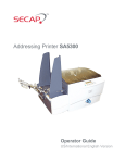
1
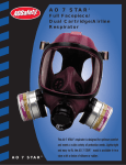
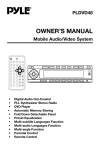
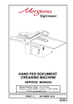
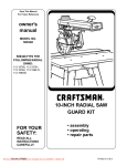
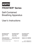
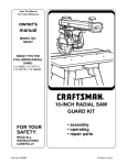
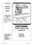
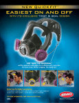
Viking ST SCBA
with Digital Indicators
ISI Viking ST...
A vital part of
your arsenal
User's Manual
Copyright
2002 International Safety Instruments, Inc.
COPYRIGHT 2002 INTERNATIONAL SAFETY INSTRUMENTS
User
s Man
ual
Users
Manual
for the
ISI Viking ST
with Digital Indicators
Self Contained Breathing Apparatus
MODELS
VIKING ST, 2216 PSI, 30 MINUTE
NIOSH APPROVAL TC-13F-508
VIKING ST, 4500 PSI, 30 MINUTE
NIOSH APPROVAL TC-13F-509
VIKING ST, 4500 PSI, 45 MINUTE
NIOSH APPROVAL TC-13F-510
VIKING ST, 4500 PSI, 60 MINUTE
NIOSH APPROVAL TC-13F-511
WARNING
Disassembly of the components beyond the procedures described
herein shall not be performed. Additional disassembly may cause
component damage and shall only be performed by authorized personnel or the factory.
INTERNATIONAL SAFETY INSTRUMENTS, INC
922 HURRICANE SHOALS ROAD LAWRENCEVILLE, GA 30043-4201
PHONE 770-962-2552 888-ISI-SAFE (toll free) FAX 770-963-2797
www.intsafety.com E-Mail: [email protected]
Part Number 084073
Artwork Number A49118
Issue A
Issue A
September 4, 2002
September 4, 2002
COPYRIGHT 2002 INTERNATIONAL SAFETY INSTRUMENTS
TABLE OF CONTENTS
PREFACE-IMPORTANT POINTS
Intent
Training
NIOSH warnings
Cautions and Limitations
Special or Critical User Instructions
1.0
2.0
3.0
4.0
5.0
1
1
1
1
2
2
DESCRIPTION OF VIKING ST
2
1.1
1.2
1.3
1.4
1.5
1.6
1.7
1.8
1.9
2
3
3
3
3
4
4
4
5
Facemask
AirSwitch Regulator
First Stage Pressure Reducer
End-of-Service Alarms
Backframe and Harness
Cylinder and Valve Assembly
Control Console Display
Flashing Locator Lights
Viking ST Cylinder Table
ROUTINE CHECKS
5
2.1
2.2
2.3
5
5
5
Unpacking
Inventory and Examination
Routine Checks and Inspections
DONNING PROCEDURES AND SAFETY
CHECKS
7
3.1
3.2
7
8
Donning Procedures
Safety Checks
DURING USE
9
4.1
4.2
4.3
4.4
4.5
9
9
10
10
11
Reading the Mask Pressure Display
Normal Use
Instructions for Changing Cylinders
Cylinder Band Adjustment
Emergency Egress Indicators
AFTER USE PROCEDURES
11
5.1
11
Doffing
6.0
7.0
8.0
9.0
10.0
11.0
12.0
AFTER USE CLEANING
12
6.1
6.2
12
12
Clean Facemask
Cleaning SCBA
SCBA STORAGE
12
7.1
12
SCBA Storage
USER MAINTENANCE
13
8.1
8.2
8.3
8.4
8.5
8.6
13
13
13
14
15
16
Cylinder Filling Procedures
Battery Pack Maintenance
Facemask Disassembly
Facemask Harness Replacement
Backframe Harness
Viking ST Components
AIRLINE ATTACHMENT
19
9.1
9.2
9.3
19
19
19
Description and Limitations
Donning with Supplied Air
Operation
BUDDY BREATHER TETHER
20
10.1
10.2
20
20
Description and Limitations
Operation
VIKING ST FEATURES
21
11.1
11.2
11.3
21
21
21
Stealth Mode
Low Battery Warning & Replacement
Communications
WARRANTY
22
TROUBLESHOOTING DEV
23
COPYRIGHT 2002 INTERNATIONAL SAFETY INSTRUMENTS
PREFACE
IMPORTANT POINTS - PLEASE READ CAREFULLY
FAILURE TO PROPERLY USE AND MAINTAIN THIS
PRODUCT COULD RESULT IN INJURY OR DEATH
INTENT
This manual is intended to acquaint owners and users with
operation for the ISI Viking ST Self-Contained Breathing Apparatus and to provide important safety information and limitations. All information, illustrations and specifications in this
manual are based on the latest product information available at
the time of printing. The right is reserved to make changes at any
time without notice.
IMPORTANT
ALL PERSONNEL USING THIS APPARATUS SHALL BE
THOROUGHLY TRAINED BY A QUALIFIED INSTRUCTOR
IN DONNING, OPERATION, INSPECTION AND EMERGENCY OPERATION.
EQUIPMENT SHOULD BE THOROUGHLY CHECKED AND
CLEANED AFTER EXPOSURE TO INTENSE HEAT OR
HARSH CHEMICALS.
The ISI Viking ST pneumatics and digital components are
designed to be simple to use and easy to maintain and will
operate for many years if properly maintained and cleaned. The
instructions for care and use given in this manual must be read,
understood and carefully followed before the apparatus is used.
The procedures in this manual DO NOT render ISI liable for any
losses or injury arising from any actions based on use of same.
Spare parts and accessories are available through your local ISI
authorized distributor. Service beyond the scope of this manual
is not recommended. If a problem persists, the apparatus
should be removed from service, tagged for repair and forwarded to an authorized ISI distributor or to the factory for evaluation
and/or repair. Do not mark the unit with inks or paints which
might be flammable or cover any label.
TRAINING
ISI strongly recommends that the training program used be
consistent with Occupational Safety and Health Programs.
Training and servicing programs are available upon request.
Please contact ISI or your local distributor for further details.
NIOSH/OSHA WARNINGS
The following warnings are given in accordance with accepted
safety conventions and/or NIOSH/OSHA requirements, and
apply to the use of breathing apparatus in general.
HEALTH LIMITATIONS: Wearers of the SCBA should be
certified medically fit prior to use. In addition, there are both
physiological and psychological limitations which should be
considered before using SCBA. They include, but are not limited
to:
*
*
*
*
*
*
*
*
*
*
*
*
*
*
Emphysema
Chronic obstructive pulmonary disease
Bronchial asthma
X-ray evidence of pneumonia
Evidence of reduced pulmonary function
Coronary artery disease
Severe or progressive hypertension
Epilepsy (grand mal or petit mal)
Pernicious anemia
Diabetes (insipidous or mellitus)
Breathing difficulties when wearing an SCBA
Claustrophobia or anxiety when wearing an SCBA
Abnormal EKG results from resting or stress tests
Punctured or ruptured ear drum
WORKING TEMPERATURES: The ISI Viking ST is approved
for respiratory protection during entry into or escape from
oxygen deficient atmospheres, gases, and vapors at temperatures above -25°F. When used below freezing, care must be
exercised to prevent moisture from entering the demand exhalation valve. The facemask should remain on the docking clip
when not in use. This includes when cylinders are being
changed.
DURATION OF USE: Although the ISI Viking ST has been
approved as either a 30-minute, 45-minute, or 60-minute breathing apparatus, the wearer’s varying work rate, physical condition and other factors could substantially shorten the actual
usable duration of the unit.
SCBA LIMITATIONS: A SCBA can only protect the wearer’s
respiratory system. Other protection may be necessary to avoid
contamination through skin absorption. If these types of materials are suspected, an effective full-body covering of impermeable material must be worn with the SCBA. A universal Class A
HazMat suit pass through is available for the ISI Viking ST from
HazMat suit manufacturers.
FACIAL HAIR: Facial hair or any items which may interfere with
the facemask-to-face seal, or in the operation of the exhalation
valve, must not be allowed. These include beards, sideburns,
mustaches, bangs, head coverings, or anything that may interfere with the correct seal of the facemask to the face.
EYE WEAR: Eye glasses shall not be used when the temple
bars interfere with the proper seal of the facemask to the face.
If a user must wear corrective lenses while wearing the SCBA,
they can be mounted in the facemask using a special lens
mounting kit (ISI part number 136001) available from ISI or
through your local ISI distributor.
MANUAL BYPASS OF THE AIRSWITCH REGULATOR: In
compliance with NIOSH requirements, the ISI Viking ST has a
manually operated bypass which provides a continuous flow of
air to the facemask when required, independent of normal
operation of the regulator. The bypass is opened by turning the
knob on the AirSwitch 90 degrees in the direction shown by the
knob arrow. Use of the bypass will shorten the duration of the
SCBA.
COPYRIGHT 2002 INTERNATIONAL SAFETY INSTRUMENTS
1
CAUTIONS AND LIMITATIONS
SPECIAL OR CRITICAL USER’S INSTRUCTIONS
•
Airline respirators can be used only when the respirators are
supplied with respirable air meeting the requirements of CGA G7.1 Grade D or higher quality.
•
Approved for respiratory protection during entry into or escape
from oxygen deficient atmospheres, gases and vapors at
temperatures above -25°F.
•
Use only the pressure ranges and hose lengths specified in the
User's Instructions.
•
•
Contains elecrtical parts which have not been evaluated as an
ignition source in flammable or explosive atmospheres by MSHA/
NIOSH.
Approved only when compressed gas container is charged with
air meeting the requirements of CGA G-7.1 Grade D or higher
quality that has a dew point of -65°F or lower and a maximum
particulate level of 5 mg/m3 air.
•
•
Failure to properly use and maintain this product could result in
injury or death.
The compressed gas container shall meet applicable DOT
specifications.
•
•
All approved respirators shall be selected, fitted, used and
maintained in accordance with MSHA, OSHA, and other
applicable regulations.
When used as a combination apparatus, only 20% of the service
pressure may be used on entry.
•
Never substitute, modify, add, or omit parts. Use only exact
replacement parts in the configuration as specified by the
manufacturer.
This approval applies only when the device is supplied with
respirable breathing air through 6 to 300 feet of hose at air
pressures between 80 and 120 pounds per square inch gauge
or from self contained air supply.
•
If the supplied air fails, open the cylinder valve and proceed to
fresh air immediately.
Refer to User's Instructions and/or maintenance manuals for
information on use and maintenance of these respirators.
•
Use adequate skin protection when worn in gases and vapors
that poison by absorption (example: hydrocyanic-acid gas).
•
•
•
Special or critical User's Instructions and/or specific use
limitations apply. Refer to User's Instructions before donning.
1.0 DESCRIPTION OF ISI VIKING ST SCBA
The ISI Viking ST consists of several major components described in the following paragraphs:
AirSwitch
Backframe
1.1
FACEMASK
Console
Single Curve
The ISI Viking ST is a self-contained, open-circuit, compressed-air breathing apparatus which is approved by the
National Institute of Occupational Safety and Health (NIOSH).
Positive pressure is maintained within the facemask during
use, thus providing the highest degree of respiratory protection in irrespirable atmospheres by preventing any inward
leakage.
2
Double Curve
The ISI full facemask assembly has a four-point adjustable
head harness in neoprene or a two point pull-forward
(Nomex or nylon) net with an optically-corrected, high-impact
polycarbonate visor. Two visors are available, single curvature and double curvature. The visor’s scratch-resistant coating conforms to NFPA standards. The interior of the visor has
a permanent anti-fog coating. The facemask seal is a highstrength silicone and has a patented blended shape. A standard inner-mask nosecup reduces dead-air space and CO2
buildup.
COPYRIGHT 2002 INTERNATIONAL SAFETY INSTRUMENTS
An in-mask display is mounted to the inner-mask nosecup.
The mask display includes five LEDs: 2 green, 2 yellow, and 1
red. The mask display indicates remaining cylinder pressure,
provides a primary end-of-service alarm and a low battery
warning. The mask display can provide additional status
indicators depending upon the options ordered.
1.3
FIRST STAGE PRESSURE REDUCER
Pressure
Reducer
yellow (B)
(low battery)
green
yellow
Air leaves the cylinder, passes through a sintered bronze filter in the handwheel elbow assembly, and then continues on
through a high pressure flexible hose to the first-stage pressure reducer where it is reduced to approximately 125 psi.
The reducer is a simple piston type that requires no adjustment and incorporates an automatic, self-seating pressure relief valve to protect the downstream low-pressure components. It is made of high quality aluminum, and is securely
mounted inside the backframe assembly.
red
1.2
1.4
AIRSWITCH® REGULATOR
The patented AirSwitch second stage regulator combines the
demand and exhalation valves and greatly reduces breathing
resistance which allows for longer duration of cylinder use. A
speech diaphragm provides excellent clarity and voice reproduction and incorporates the exhalation valve. The AirSwitch
regulator is incorporated into the facemask and combines inhalation and exhalation into one assembly.
REMOTE CYLINDER PRESSURE AND ENDOF-SERVICE INDICATORS
The digital pressure gauge is incorporated in the control console located on the left shoulder strap. Cylinder pressure is
displayed in the console with a two digit value which represents hundreds of psi (e.g. 45 = 4500 psi).
The primary end-of-service alarm is incorporated in the mask
display. The mask display will flash a single red LED at 23% 27% of rated cylinder pressure per NIOSH requirements.
1.5
BACKFRAME AND HARNESS
bypass
knob
The AirSwitch features a fresh air mode which allows users
to go from cylinder or supplied air to outside air by depressing
the two control slide tabs inward and then raising the slide upwards fully. Push down for cylinder or supplied air. The AirSwitch should stay open prior to donning and doffing of the
ISI Viking ST SCBA. The AirSwitch is made of high performance engineered plastics and incorporates a true manual
bypass control for emergency use.
The backframe and harness assembly utilize ergonomic design principles to produce a comfortable, low profile unit that
evenly distributes the SCBA weight between the wearer’s
hips and shoulders. (*Shown with optional KEVLAR® cylinder
sleeve.)
COPYRIGHT 2002 INTERNATIONAL SAFETY INSTRUMENTS
3
The unique double-wall backframe on the ISI Viking ST protects major airlines, the first stage reducer and digital components. A quick-release cylinder band fits a wide range of cylinders with an infinitely adjustable latch to ensure a tight fitting cylinder.
The harness material is custom woven KEVLAR® or nylon.
The upper harness has very resilient foam rubber padding
for added comfort and PBI/KEVLAR cover for maximum durability and protection. A lumbar pad is standard for added
comfort and support.
The backframe assembly also houses the battery pack assembly for the digital components. The battery pack accommodates two sets of four AA alkaline batteries. Each set is independent of the other. If one battery or battery set fails, the
other set will continue to power the digital components.
1.6
CYLINDER AND VALVE ASSEMBLY
A range of cylinder types and capacities are accommodated
on the ISI Viking ST 2216 psi and 4500 psi models. (Please
see the table in Section 1.9 for specifics.)
1.7
CONTROL CONSOLE DISPLAY
The Control Console display, depending on the options purchased, will display cylinder pressure and communications
within the console display. See Section 11.0 for additional
information. The Control Console is mounted on the upper
left shoulder strap. As with the In-mask Display, the console
display turns on automatically when the cylinder valve is
opened. For units calibrated in pounds per square inch (psi),
the console display shows hundreds of psi (example: “45”
means 4500 psi). For units calibrated in Bar, the “300”
means 300 bar. As an additional feature, when the Control
Console display is turned on manually by simultaneously
pressing both of the control buttons, the console display
briefly shows maximum pressure rating (“22” for 2216 psi or
“45” for 4500 psi), the software version installed (e.g. “602”)
and then the cumulative hours of usage (first displays “Hr X”
- when displays “YYY” - where total hours of usage equals x,
yyy). An example of hours displayed would show Hr 1 and
then would display 235. The cumulative hours would be
1235 hours of usage. The cumulative usage time will be
used to determine proper maintenance intervals. To manually turn off the Control Console, close cylinder valve, bleed
pressure from pneumatics by opening bypass knob and then
push in simultaneously on both Control Console buttons.
1.8
FLASHING LOCATOR LIGHTS
The cylinder valve is of forged aluminum construction with a
permanent teflon coating. The valve outlet is a standard
CGA-346 fitting on 2216 psi cylinders, and a standard CGA347 fitting on 4500 psi cylinders. Each valve has a frangible
disc safety relief device, and a dual-reading pressure gauge.
HANDLING PRECAUTIONS:
NEVER LIFT OR CARRY UNIT BY THE HIGH PRESSURE
HOSES. IF A HIGH PRESSURE HOSE BECOMES KINKED
OR OTHERWISE DAMAGED, IT SHOULD BE REPLACED.
CHECK FOR DAMAGE NEXT TO THE METAL ENDS OF
THE HOSE.
4
Flashing Locator Lights are located along each side of the
cylinder. The pair of high intensity, long life LED’s flash approximately every second whenever the unit is on to aid in
locating a user in low visibility conditions. These lights can
be deactivated by the user.
COPYRIGHT 2002 INTERNATIONAL SAFETY INSTRUMENTS
1.9
VIKING ST CYLINDER TABLE
Part
Number
Pressure
PSIG
Free Air
Capacity
Material
NIOSH
Rated
Duration
@ 40 lpm
Cylinder
& Valve
Charged
Weight
Cylinder
Diameter
Hydrostatic
Interval
024.037.00
2216
Aluminum
1287 liters
45 cu. ft.
30 min.
20.5 lbs.
6.9 in.
5 years
024.035.00
2216
Hoop-Wrapped
Aluminum
1301 liters
45.5 cu. ft.
30 min.
16.0 lbs.
6.9 in.
3 years
124001
2216
Full Wrapped
Carbon
1301 liters
45 cu. ft.
30 min.
10.4 lbs.
6.8 in.
5 years*
124027
4500
Hoop-Wrapped
Aluminum
1287 liters
45 cu. ft.
30 min.
15.9 lbs.
5.5 in.
3 years
124028
4500
Full Wrapped
Carbon
1287 liters
45 cu. ft.
30 min.
11.0 lbs.
5.4 in.
5years*
124029
4500
Full Wrapped
Carbon
1887 liters
66 cu. ft.
45 min.
14.8 lbs.
6.8 in.
5 years*
124030
4500
Full Wrapped
Carbon
2516 liters
88 cu. ft.
60 min.
19.2 lbs.
7.1 in.
5 years*
*All Carbon Cylinders with E10915 have 5 year hydrostatic intervals.
2.0 ROUTINE CHECKS
2.1
UNPACKING
Open the storage case or shipping container. Observe the
relative position and placement of the various components
for future re-packing. Remove the SCBA from the container
and place on a clean dry surface. Remove the facemask
from protective bag. Remove battery pack from protective
bag. Install battery pack into backframe according to battery
pack installation instruction in section 8.2.
2.2
2.3.1
Visually inspect complete apparatus for worn or
aged parts and damaged components.
2.3.2
Basic cylinder inspection shall include:
A. Inspect gauge for damage.
B. Inspect cylinder for mechanical damage (cracks,
dents, gouges) or signs of heat or chemical
damage. (Refer to CGA C-6.2 Guideline for Visual
Inspection and Requalification of Fiber Reinforced
High Pressure Cylinders for all wrapped cylinders.)
C. Check that hydrostatic test date on cylinder is
current.
D. Check that cylinder valve threads are not damaged.
E. Check that the valve body is not bent.
F. Check that the burst disc outlet is clean and free of
debris.
G. If any item listed above is noted, depressurize
cylinder to a slight positive pressure, tag, and take
out of service.
INVENTORY AND EXAMINATION
Examine unit for physical condition and appearance of all
components. Be sure the following major components are included:
• Facemask and AirSwitch Assembly in Storage Bag
• Backframe and Harness Assembly
• Cylinder and Valve Assembly
• Options ordered with unit
• Battery Pack
2.3
WARNING
THE APPARATUS MUST NOT BE USED UNTIL THE FOLLOWING TESTS HAVE BEEN SUCCESSFULLY COMPLETED. ANY DISCREPANCY NOTED DURING THE PRE-USE
CHECK AND INSPECTION SHALL BE CORRECTED ONLY
BY AUTHORIZED PERSONNEL PRIOR TO USE OF THE
APPARATUS.
ROUTINE CHECKS AND INSPECTIONS
The following procedure shall be used for incoming and daily
inspection of the apparatus. A SCBA not routinely used, but
kept for emergency use, shall be inspected at least monthly.
All other apparatus shall additionally be inspected after each
use.
COPYRIGHT 2002 INTERNATIONAL SAFETY INSTRUMENTS
5
Push IN and UP
to open
2.3.3
Open control slide on AirSwitch by pressing inward
and upward on two protruding features on both
sides of control slide. Also make sure the bypass
knob is in the closed position, i.e., fully turned clockwise when looking at front of mask.
2.3.4
Open the cylinder valve slowly by turning the cylinder valve knob counter-clockwise to the fully open
position. The console will emit an audible chirp.
There should be no air flow from the facemask. If air
is flowing, check that the bypass valve is closed.
Push DOWN
to close
2.3.6
While holding the facemask, push down on the top
of the control slide to close the AirSwitch and
QUICKLY push back to the UP position. There will
be a rush of air when the slide is pushed down, and
the air flow must stop when the slide is in the UP
position.
2.3.7
Open bypass and check for constant air flow. Close
bypass.
2.3.8
BATTERY CHECK: Check the control console display for a low battery indication. If the batteries are
low, the control console will alternately display cylinder pressure and "LoB" and the top yellow LED light
will be on in the in-mask display. If the control console displays a low battery warning, replace batteries in accordance with section 8.2, Battery Pack
Maintenance.
2.3.9
LEAK TEST OF APPARATUS: With control slide in
the OPEN position, close the cylinder valve. The
digital pressure gauge must not drop more than 300
psi per minute.
2.3.10
LOW PRESSURE ALARM TEST: Gradually reduce
the system pressure by slightly opening the bypass
valve. Verify that the mask display blinks a single
red LED between 600-500 psi for 2216 SCBA and
between 1200-1000 psi for 4500 psi SCBA.
2.3.11
Return apparatus to storage, or proceed to donning
instructions.
WARNING
ENSURE THAT ONLY A 2216 PSI CYLINDER IS USED
WITH LOW PRESSURE PNEUMATICS AND A 4500 PSI
CYLINDER IS USED WITH HIGH PRESSURE PNEUMATICS.
2.3.5
CHECK CYLINDER PRESSURE: The digital pressure gauge must read at or above 1900 psi for 2216
SCBA and at or above 3900 psi for 4500 psi SCBA.
The mask display must light all four LEDs (the last
green LED may blink). If no lights activate the control console is not functioning properly. If cylinder
pressure is below the specified levels, refill cylinder
or replace with a fully charged cylinder.
IMPORTANT
COMPLETE ALL ROUTINE CHECKS AND INSPECTION
PROCEDURES OUTLINED IN SECTION 2 BEFORE STARTING DONNING PROCEDURES, SECTION 3.
WARNING
IF ANY OF THE ABOVE TESTS FAIL, REMOVE APPARATUS FROM SERVICE, TAG, AND RETURN FOR REPAIR
BY AUTHORIZED PERSONNEL.
TECHNICIAN MAINTENANCE
AFTER EVERY 100 HOURS OF USE, OR AT LEAST ONCE
PER YEAR, THE ENTIRE SCBA SHOULD BE PLACED
OUT OF SERVICE AND TAGGED FOR COMPREHENSIVE
MAINTENANCE BY AUTHORIZED TRAINED TECHNICIAN.
6
COPYRIGHT 2002 INTERNATIONAL SAFETY INSTRUMENTS
3.0 DONNING PROCEDURES AND SAFETY CHECKS
3.1
DONNING PROCEDURES
3.1.1
Position the ISI Viking ST on the ground with the cylinder valve facing away from the wearer.
3.1.2
3.1.3
3.1.4
3.1.5
Connect the waistbelt buckle and adjust waistbelt to
a comfortable snug fit by pulling simultaneously on
both left and right adjustment straps. Tuck the excess waistbelt and shoulder strap pull-downs inside
the waistbelt.
3.1.6
With one hand on the head harness straps, put chin
into facemask first and pull harness straps over
head. Position facemask so that chin fits snugly into
chin cup.
3.1.7
Ensure the AirSwitch control slide is in the UP
(open) position, and the bypass valve is closed. To
connect the facemask to the console, connect display plug partially into socket, then connect hose
plug into connector. Press firmly in to lock both fittings into each socket.
Note:
When connecting the facemask hose to hose connector, make sure both hoses are connected and the
socket sleeve has moved forward. If socket sleeve is
moved forward without the facemask hose connected, air will leak out of the socket connector.
Spread the shoulder straps and fold open the side
arms. Ensure all strap assemblies, side and waist,
are fully extended and waist belt buckle assembly is
not connected. Reach inside the harness assembly
and grasp the frame with both hands.
Swing the unit up and over the head, making sure
that the elbows extend through the loops formed by
the shoulder straps. Allow the unit to slide down the
back.
Pull directly down on the shoulder straps to adjust
position of unit on back, attach optional chest strap,
if applicable.
COPYRIGHT 2002 INTERNATIONAL SAFETY INSTRUMENTS
7
WARNING
BE SURE TO ALIGN CONNECTOR AND DISPLAY PLUG
CORRECTLY AS SHOWN. DAMAGE WILL RESULT TO
THE PIN IN THE AIR HOSE CONNECTOR IF THE DISPLAY
PLUG IS PUSHED IN IT.
3.1.8
It is not necessary to perform a negative pressure
check because the AirSwitch regulator and
facemask are designed as a positive pressure
facemask.
3.2.2
ALARM CHECK: Close the cylinder valve and continue to breathe normally. Verify that the mask display blinks a single red LED between 600-500 psi for
2216 SCBA and between 1200-1000 psi for 4500 psi
SCBA. Open cylinder valve fully.
3.2.3
With cylinder valve open, take two to three deep
breaths to ensure you are getting adequate air into
the facemask. The facemask should not move towards your face.
Open the cylinder valve slowly by turning the cylinder valve counter-clockwise to the fully OPEN position. The control console should emit an audible
chirp.
Pull straps
FORWARD
on net
harness
3.1.9
Note:
Bypass
Knob
For Optional Net Head Harness: Pull straps outward
and then forward to adjust facemask tightness. Pull
net toward base of skull to ensure it is seated fully.
For Standard Rubber Spider: Pull straps back to adjust facemask tightness. Pull both lower straps first,
then both upper. Be sure to pull the straps in pairs.
Pull spider toward base of skull to ensure it is
seated fully. The upper straps have two positions.
Select the position which brings the spider to the
base of the skull.
3.2.4
BYPASS CHECK: The bypass knob is located in
the top center of the AirSwitch. Turn the bypass
knob in the direction shown by the knob arrow to
open the bypass valve. A constant flow of air should
pass into the facemask. Turn the knob in the opposite direction to turn the bypass valve off. (Do not
over tighten.)
3.2.5
RE-CHECK CYLINDER PRESSURE: Check the
digital pressure gauge. The gauge should read at or
above 1900 psi for a 2216 psi cylinder and 3900 psi
for 4500 psi cylinder. The mask display must light
the first four LEDs (the last green LED may blink).
Breathe normally and proceed as planned.
IMPORTANT
DO NOT OVER-TIGHTEN THE FACEMASK. DOING SO
MAY CAUSE DISCOMFORT OR FACEMASK DEFORMATION AND LEAKAGE.
3.2
SAFETY CHECKS
WARNING
THESE SAFETY CHECKS MUST BE PERFORMED BEFORE ENTERING A HAZARDOUS AREA. FAILURE TO
PERFORM THESE CHECKS MAY RESULT IN RESPIRATORY INJURY OR DEATH.
3.2.1
8
POSITIVE PRESSURE FIT CHECK: With cylinder
valve open, push down on the control slide to activate air supply and breathe normally. Insert two fingers between the facemask and face. Gently lift the
facemask seal away from the face and ensure a
good outward flow of air, showing that the facemask
pressure is positive. Reseal facemask and stop
breathing for 3 seconds. There should be no sound
of air leaking from the AirSwitch regulator, and there
should be no airflow sensed in the eye region of the
mask.
COPYRIGHT 2002 INTERNATIONAL SAFETY INSTRUMENTS
3.2.6
BATTERY CHECK: Check the Control Console display or in-mask display for a low battery indication. If
the batteries are low, the Control Console will alternately display cylinder pressure and "LoB" and an
audible beep every 12 seconds and the top yellow
light from the in-mask display will be "on". No audible sound is made while in stealth mode. If the
Control Console displays a low battery warning, replace batteries in accordance with section 8.2, Battery Pack Maintenance.
WARNINGS
IF ANY OF THE ABOVE CHECKS FAIL, DO NOT PROCEED. REMOVE THE APPARATUS FROM SERVICE, TAG,
AND RETURN FOR REPAIR BY AUTHORIZED PERSONNEL.
USE OF THE BYPASS IN NON-EMERGENCY SITUATIONS
WILL SUBSTANTIALLY REDUCE DURATION OF THE APPARATUS.
THE BYPASS WILL NOT FUNCTION IF THE CYLINDER IS
OUT OF AIR.
4.0 DURING USE
IMPORTANT
THE USER MUST RECEIVE TRAINING ON HOW TO
HANDLE A POSSIBLE EMERGENCY BEFORE ENTERING
A HAZARDOUS AREA.
The ISI Viking ST SCBA can be equipped with a variety of
fully-integrated solid state features that offer safety and
communication advantages for the user. Review section 11.0,
"Stealth Features," for detailed instruction of available options.
Remaining
Cylinder RED YELLOW GREEN GREEN YELLOW
Pressure
•
Full
•
•
•
•
•
Full → 3/4
•
•
•
3/4 → 1/2
•
1/2 → 1/4
Below 1/4
Low Battery
•
• = On
4.1 READING THE MASK PRESSURE DISPLAY
4.1.2
yellow (B)
(low battery)
green
yellow
= Blinking
= Off
One additional yellow light is above the height of the
rest of the lights in the sequence. This yellow light
indicates low battery status and will come on only
when the batteries are low. The unit will continue to
function fully for several hours if the light comes on
while in use. If the low battery light shows at start-up,
the batteries should be replaced with fresh ones
before putting the unit in service.
red
4.1.1
The mask pressure display includes five LED lights:
two green, two yellow and one red. Each of the 4
LEDs in a row represents a quarter increment of the
rated service pressure. As cylinder pressure decreases, the LEDs change status. At full rated service
pressure, all four LEDs are on. As cylinder pressure
drops below full, the last green LED begins blinking.
At 3/4 rated service pressure, the last green LED
turns off and the next green LED begins blinking. At
1/2 rated service pressure, the green LED turns off
and the yellow LED begins blinking. At 1/4 rated
service pressure, the yellow LED turns off, and the
red LED blinks at a fast rate. Refer to the following
table for more information regarding mask pressure
display interpretation.
4.2
NORMAL USE
4.2.1
The Control Console displays cylinder pressure as a
two digit number. The digital numbers correspond to
the flashing lights inside the facemask which represent quarter increments of cylinder pressure. Monitor
cylinder pressure for remaining air supply using the
Control Console, the in-mask display or both. Refer
to chart in section 4.1.1 for the LED light sequence.
4.2.2
The end-of-service-time alarm (mask display)
activates when there is approximately 25% of the full
air supply remaining. Egress when the alarm
activates. WARNING: 25% OF A FULL CYLINDER
MAY BE INSUFFICIENT IN SOME CIRCUMSTANCES TO SAFELY EXIT FROM AN IDLH
ATMOSPHERE. One example would be a longdistance ingress through a continuous IDLH (Immediately Dangerous to Life or Health) atmosphere. In
such situations, begin egress prior to activation of
the end-of-service-time indicator.
COPYRIGHT 2002 INTERNATIONAL SAFETY INSTRUMENTS
9
4.3
INSTRUCTIONS FOR CHANGING
CYLINDERS
4.3.1
Make sure cylinder valve is closed and all air is released from the pneumatic sytem.
4.3.2
Press down in the center of the locking latch to
release lock. While doing so, lift up on latch to
relieve cylinder band tension.
4.3.3
Disconnect handwheel from cylinder valve and remove cylinder by sliding cylinder upward through
cylinder band.
4.3.4
Insert new full cylinder by sliding down through
cylinder band until cylinder rests against bottom
retainer.
4.3.5
Connect handwheel to cylinder valve and position
cylinder.
4.3.6
Close the locking latch.
4.4
4.4.1
10
CYLINDER BAND ADJUSTMENT
Make sure cylinder valve is closed and air is released from the pneumatic system.
4.4.2
Press down in the center of the locking latch to release lock. While doing so, lift up on latch to relieve
cylinder band tension.
4.4.3
Press in both adjustment latch buttons. While doing
so, lift up and completely open the latch.
4.4.4
To loosen the cylinder band, grab the inner cylinder
band strap and pull out/away from the adjustment
latch. To tighten the cylinder band, grab the outer
cylinder band strap and pull up/away from the
adjustment latch. Make sure that the locking latch is
in the open position. Slide the slack across the inner
strap.
COPYRIGHT 2002 INTERNATIONAL SAFETY INSTRUMENTS
4.5
4.4.5
Further adjust cylinder band length until tight. Make
sure that the locking latch is in the open position.
Once tight, close the adjustment latch. Slide the
slack across the lower strap.
4.4.6
Connect handwheel to cylinder valve and position
cylinder.
4.4.7
Close the locking latch.
5.0
EMERGENCY EGRESS INDICATORS
If any of the following situations occur, egress immediately:
A. Exposure to flashover
B. Exposure to high temperature
C. Harness failure
D. Chattering or unusual noises from SCBA
E. Submersion in water (Note: In this situation the ISI Viking ST
will continue to supply air on demand to a depth of at least
3 meters.)
F. SCBA subjected to high impact such as a fall
G. Air flow decreases such that the facemask moves inward
toward the face during inhalation (Note: In this situation,
open bypass to provide extra, constant flow.)
H. Air flows constantly at a high rate (Note: In this situation,
adjust the flow rate by slowly closing the cylinder valve until
a comfortable flow rate in established. The flow rate should
match the bypass flow rate during normal operation.)
I. Stealth pressure gauge, mask pressure display, or other
digital options cease to function properly.
AFTER USE PROCEDURES
IMPORTANT
DO NOT REMOVE ANY EQUIPMENT UNTIL YOU ARE
CLEAR OF AN IDLH ATMOSPHERE.
WARNING
DURING COLD WEATHER OPERATIONS, THE AIRSWITCH
REGULATOR SHOULD BE STORED IN THE CLOSED
POSITION (CONTROL SLIDE DOWN) TO PREVENT ICE
BUILD-UP INSIDE THE REGULATOR. THIS PRACTICE IS
NECESSARY AS ICE MAY INTERFERE WITH THE SEALS
OF THE AIRSWITCH REGULATOR WHILE IN USE.
TO AVOID DAMAGE TO THE VISOR, DO NOT PLACE THE
FACEMASK DOWN ON ROUGH SURFACES.
5.1.6
Place facemask on the shoulder harness snap
hook.
5.1.7
Unfasten the waistbelt and loosen shoulder straps.
Extend shoulder straps and waistbelt fully. Unhook
chest strap if applicable.
Close the cylinder valve by turning it fully clockwise.
5.1.8
Remove the apparatus.
5.1.4
Release air pressure in the system by opening the
bypass until the air flow stops, then closing it.
5.1.9
Remove the cylinder and tag it for refilling. See
Section 8 for instructions.
5.1.5
Turn off electronics by simultaneously depressing
round buttons on both sides of the control console.
5.1.10
Do not store or place apparatus in ready position
until after performing “After Use Cleaning”
Section 6.
5.1
DOFFING
5.1.1
Push the control slide UP on AirSwitch.
5.1.2
Loosen head harness straps fully and remove
facemask.
5.1.3
COPYRIGHT 2002 INTERNATIONAL SAFETY INSTRUMENTS
11
6.0
AFTER USE CLEANING
6.1
CLEANING FACEMASK
6.1.1
Disconnect demand valve hose connector by pushing connector into socket and pulling back on the
socket sleeve. Open the AirSwitch.
6.1.2
6.1.3
Wash the facemask in cool to warm soapy water.
Use a mild, non-detergent, dish washing soap (e.g.
Ivory). The mask display is completely submersible.
Do not immerse the hose end connector in water.
After rinsing, shake to remove excess water, plug
into low pressure line and close AirSwitch to allow
free-flow for a few seconds. Repeat process several
times.
NOTE: Where futher cleaning due to heavy contamination
is required, clean with ISI recommended disinfectant/cleaner (Part Number 013003 or 013004) after
rinsing the facemask. Use of other disinfectants
may cause damage to scba components. Consult
with ISI customer service toll free 1-888-ISI-SAFE.
6.1.4
6.1.5
Ensure all head harness straps are fully extended,
ready for use.
WARNING
IF THE APPARATUS IS LIKELY TO BE STORED AT TEMPERATURES BELOW FREEZING (32°F), THE FACEMASK
MUST BE THOROUGHLY DRIED WITH PARTICULAR ATTENTION TO THE AIRSWITCH.
6.2
CLEANING SCBA
6.2.1
Fully extend shoulder straps and waistbelt to full
open position. Clean off any dirt with a medium
bristle brush or sponge and a mild, non-detergent
dishwashing soap. DO NOT USE BLEACH OR ANY
COMPOUND CONTAINING CHLORINE AS THIS
WILL TEND TO RAPIDLY DETERIORATE FABRIC.
CAUTION
IF IT IS NECESSARY TO CLEAN THE EXTERIOR OF THE
AIRSWITCH, CARE SHOULD BE TAKEN TO ENSURE NO
TRACE AMOUNTS OF WATER ARE LEFT IN THE
AIRSWITCH OPENING. CONNECT UNIT TO FULL CYLINDER AND ACTIVATE THE AIRSWITCH'S BYPASS AND
CONTROL SLIDE TO BLOW WATER OUT, PARTICULARLY
IF THE APPARATUS IS TO BE USED OR STORED AT TEMPERATURES BELOW FREEZING.
WARNING
DO NOT IMMERSE THE CONTROL CONSOLE IN
WATER. PERFORM ALL TESTING AND MAINTENANCE
WORK IN A CLEAN ENVIRONMENT.
NOTE: The Control Console should be cleaned or decontaminated by using a clean, damp cloth with an ISI
recommended disinfectant/cleanter (Part Number
013003 or 013004).
When dry, polish the visor inside and out with a soft
clean, lint-free cloth.
7.0 SCBA STORAGE
7.1
SCBA STORAGE
7.1.1
Complete routine checks and inspection procedures
outlined in Section 2.3 of this manual.
7.1.2
Ensure complete apparatus is clean and dry.
7.1.3
Ensure AirSwitch is in the UP position, and the bypass knob is in the CLOSED position.
7.1.4
Ensure facemask and head harness straps are fully
extended. Unplug facemask assembly and store in
case, positioned to avoid distortion.
7.1.5
12
7.1.6
Place the complete apparatus in the storage case or
suitable storage place so it can be easily reached for
emergency use.
7.1.7
MOUNTING SCBA IN VEHICLE: When storing the
ISI Stealth using mounting brackets, ensure that
brackets are secure and that no sharp objects will
come in contact with the SCBA. Ensure that the
brackets do not interfere with the backframe components.
7.1.8
Ensure Control Console is turned off and is clean
and dry.
Ensure shoulder and waistbelt straps are fully extended.
COPYRIGHT 2002 INTERNATIONAL SAFETY INSTRUMENTS
8.0
USER MAINTENANCE
8.1
CYLINDER FILLING PROCEDURES
8.1.1
Basic cylinder inspection shall include:
A. Inspect gauge for damage.
B. Inspect cylinder for mechanical damage (cracks,
dents, gouges) or signs of heat or chemical
damage. (Refer to CGA C-6.2 "Guideline for Visual
Inspection and Requalification of Fiber Reinforced
High Pressure Cylinders" for all wrapped cylinders.) If the optional cylinder sleeve is used,
it must be removed for inspection.
C. Check that hydrostatic test date on cylinder is
current.
D. Check that cylinder valve threads are not damaged.
E. Check that the valve body is not bent.
F. Check that the burst disc outlet is clean and free
of debris.
G. If any item listed above is noted, depressurize
cylinder to a slight positive pressure, tag, and take
out of service.
WARNING
TO REDUCE THE RISK OF IGNITION OF A FLAMMABLE
ATMOSPHERE, BATTERIES MUST ONLY BE CHANGED IN
AN AREA KNOWN TO BE NON-FLAMMABLE
8.2.1
BATTERY PACK INSTALLATION: Push battery pack
into battery compartment such that the clips snap over
the brass pins. The Control Console will turn on, emit
an audible chirp, and then turn off. Secure battery
pack to backframe with four Torx screws.
8.2.2
BATTERY PACK REMOVAL: Loosen the four Torx
screws which secure the battery pack to the
backframe. Begin lifting battery pack out of battery
compartment by prying fingernail, coin, or flat-head
screwdriver under battery pack recess.
8.2.3
BATTERY REPLACEMENT: With the battery pack
removed from the backframe, remove old batteries
from battery pack and replace with new AA alkaline
batteries. Ensure that each battery is properly installed, noting polarity. Ensure that each battery
touches both battery pack contacts. Always replace all
batteries at the same time.
NOTE: Cylinders that are tagged for repair should always be
stored empty with the cylinder valve closed to prevent
contamination or condensation inside the cylinder.
8.1.2
Prior to filling cylinder, follow the basic inspection
procedures outlined in 8.1.1
8.1.3
Cylinder air shall meet or exceed the standards of
CGA (Compressed Gas Association) and OSHA.
8.1.4
Fill cylinder to its maximum rated pressure (FULL).
Wait at least 30 minutes to allow cylinder to cool,
then add extra air to return to full at room temperature. (Note: pressure will drop as the cylinder cools.)
8.2
8.3 FACEMASK DISASSEMBLY
Tools required: #2 Phillips screwdriver, 9/32" Nut
Driver, 3/32" Hex socket driver.
BATTERY PACK MAINTENANCE
The battery pack accommodates two sets of four AA
alkaline batteries. Each set is independent of the
other. If one battery or battery set fails, the other set
will continue to power the digital components. Fresh
batteries will provide approximately five months of
heavy usage (30 minutes use per day), approximately
12 months of light use (30 minutes use per week),
and approximately 18 months of room temperature
storage. When the batteries need replacing, the
heads-up display will activate the offset top yellow
LED light. The Control Console display will show
"LoB" on start-up and alternate "LoB" with cylinder
pressure. With Voice Amplifier or Radio Interface
options, the Control Console display speaker will
sound a unique double beep every 12 seconds and
not sound the normal start-up chirp. No audible
sound is made while in stealth mode. The unit will
continue to function fully for several hours if "LoB"
starts during use. If "LoB" shows at start-up, the
batteries should be replaced with fresh ones before
putting the unit in service.
8.3.1
VISOR REPLACEMENT: Gently pull mask display
connector away from the regulator baseplate (note
orientation of connector prior to removal).
Unscrew the four nuts inside the facemask with the
9/32" socket driver and remove the regulator. Place
the regulator so the bypass knob is facing down and
the lever that is exposed does not get damaged.
COPYRIGHT 2002 INTERNATIONAL SAFETY INSTRUMENTS
13
8.3.2
Remove nosecup (with attached mask display) and
retaining plate from facemask.
8.3.3
Remove facemask retainer clip from right side of
facemask where visor clamps are joined. Remove
visor clamps from facemask using a phillips screwdriver. Take note that the upper and lower visor
clamps are different. Pull visor clamps apart and
remove from facemask seal.
8.3.4
To reassemble, place visor in facemask seal, align
marks on top of visor to marks on top of clamp for
proper alignment. Apply a thin coating of lubricant
(liquid soap or petroleum jelly) to the entire edge of
the seal to ease installation into the clamps. Place
visor clamps on facemask aligning marks and push
together. Install phillips screws in visor clamp. Install
retaining clip on right side of facemask where the
visor clamps are joined.
8.3.5
Place nosecup (with attached mask display) and
retaining plate in facemask. Start with the bottom of
the nosecup and make sure the sealing surface is flat
against visor. Push top of nosecup into position and
check the total sealing area. Check for nosecup
alignment to make sure that the nosecup is level with
facemask. Place a small amount of non-detergent
liquid soap on the seal of the nosecup.
8.3.7
Using the 9/32" socket driver, tighten the four nuts of
the retaining plate into the regulator, while still
holding regulator in place. Tighten the four nuts
equally using an "X" pattern to 3 in-lb Pull nosecup
up and over the top of the retaining plate. The
nosecup has a notch that puts the retaining plate in
between the nosecup and the visor. Make sure that
retaining plate is correctly positioned in nosecup
notch. Plug mask display connector into regulator.
8.4
FACEMASK HARNESS REPLACEMENT
Tools Required: Harness tool
RUBBER HEAD HARNESS REMOVAL
8.4.1
Remove the rubber spider from intermediate strap by
passing the spade ends through the rollers.
Pull top intermediate straps through visor clamp
bracket. Lower straps are removed by removing
buckle button and then pulling intermediate strap
through visor bracket.
8.4.2
8.3.6
Install regulator into the facemask. Start with placing
bottom of regulator into nosecup and push inward
making sure that the seal of the nosecup is not being
pushed into the facemask and causing a leak. Push
the top of the regulator into the nosecup. Check
again to make sure that the sealing surface is flat
against the regulator.
KEVLAR NET HEAD HARNESS
8.4.3
Pull up on top retaining clip that holds head harness
in place. Slide harness through the clip and pull
through bracket. Repeat on other side. Remove
lower strap from adjuster. Pull lower straps through
bracket to remove.
8.4.4
14
To reinstall, pull upper intermediate strap through
visor clamp bracket. Pass lower intermediate strap
through visor bracket. Raised button area must face
outward. Attach buckle button to harness. Attach
rubber spider through rolller of intermediate straps.
Ribbed side must face outward.
Position new head harness to match up with
facemask.
COPYRIGHT 2002 INTERNATIONAL SAFETY INSTRUMENTS
8.4.5
Slide head harness through the two top visor
brackets using harness tool or jeweller screwdrive to
pull harness through opening.
8.4.6
Slide retaining clip through head harness and lock in
place.
8.4.7
Pull lower straps through bracket so that ribs are
facing inward and the stop is located on the outer
part of the mask.
8.4.8
Attach lower straps through adjuster rollers.
NYLON NET HEAD HEARNESS
8.4.9
Pull up on retaining clip that holds head harness in
place. Slide harness through the clip and pull
through bracket. Repeat steps to remove harness
lower straps.
8.4.10
8.4.11
8.4.12
Position new head harness to match up with
facemask.
Slide head harness through the 4 visor brackets
using harness tool to pull harness through opening.
Slide retaining clips through head harness and lock
in place.
8.4.13
Feed lower straps through buckles on back of
harness.
8.5
BACKFRAME HARNESS
8.5.1
Upper Shoulder Strap Removal/Installation:
8.5.1.5 Push upper shoulder straps into backframe approximately one inch. Turn brackets upright and pull out of
backframe.
8.5.1.6 Pass upper shoulder straps through backframe cap
slots to remove backframe cap.
INSTALLATION
8.5.1.7 Reverse the above steps.
8.5.2
Side Arm Removal/Installation
Tools required: T- 25, Loctite 222
REMOVAL
8.5.2.1 Remove any accessory that is attached to waist belt
strap.
REMOVAL
8.5.1.1 Separate lower shoulder straps from upper shoulder
straps by passing straps through buckles.
8.5.2.2 Remove side arms by using a T-25 driver to unscrew
the bottom screw.
INSTALLATION
8.5.2.3 Reverse the above steps and use Loctite 222 on
sidearm allen screws before tightening.
8.5.1.2 Unsnap regulator hose and console from left upper
shoulder strap.
8.5.3
8.5.1.3 Unsnap gauge hose from right upper shoulder strap.
Lower Shoulder Strap and Waistbelt Strap
Removal/Installation
8.5.3.1
Separate lower shoulder straps from upper
shoulder straps by passing straps through buckles.
8.5.3.2
Remove waistbelt straps by passing waistbelt
straps through lower shoulder strap buckles.
8.5.1.4 Slide backframe cap up to provide access to upper
shoulder strap brackets.
COPYRIGHT 2002 INTERNATIONAL SAFETY INSTRUMENTS
15
8.5.3.3
8.5.3.4
INSTALLATION
The female belt buckle is attached to the left side of
the backframe. The male belt buckle is attached to
the right side of the backframe (from the user's
perspective).
Pass right lower shoulder strap through right side
arm: Starting on the outside, pass strap through
side arm until buckle is positioned 3" from side
arm. Pass back to the outside, then inside, then
outside, and then inside. Pass right lower shoulder
strap through right upper shoulder strap buckle.
Do not pass strap through two slots at bottom of
side arm. Repeat instructions for left lower
shoulder strap.
8.6
VIKING ST COMPONENTS
8.6.1
Disassembly of DIGITAL INDICATORS
8.6.1.4 Remove retaining cover from pressure reducer using
a T-15 driver and remove u-clip from transducer and
console hose. Remove transducer from reducer.
Remove the low pressure console hose from the
reducer.
Tools required: T-15, #2 phillips
8.6.1.2 Remove lumbar pad on one side of ISI Viking ST to
gain access to backframe cover. Loosen the four
screws that secure the battery cover using a T-15
driver. Note: The four screws are longer than the
backframe screws and are retained in the battery
case. Remove battery assembly.
8.6.1.5 Remove the four screws from the “Black Box.”
Carefully remove the board with the transducer by
lifting up on the lower end of the black box to allow
the flashing locator lights to clear the backframe and
slide the contacts out of the battery compartment.
Making sure that the hoses don’t get in the way of the
black box and wires.
8.6.1.6 Unplug the Control Console wire from harness inside
the backframe cover.
8.6.1.3 Remove backframe cover by removing the nine
screws using T-15 driver.
16
COPYRIGHT 2002 INTERNATIONAL SAFETY INSTRUMENTS
8.6.1.7 Unsnap the hose from the left shoulder harness.
Remove the two phillips screws from the back of the
console and remove support plate. Remove the low
pressure hose from the console.
8.6.2.3 Attach the transducer into the pressure reducer.
Ensure the o-ring is in place prior to attaching hose.
U-clip in place. Attach the retaining cover to the
pressure reducer using T-15 driver.
8.6.2.4 Attach the strain relief (grommet) that is incorporated
into the wire to the top of the backframe.
8.6.2
Reassembly of DIGITAL INDICATORS
8.6.2.1 Unpack the digital components carefully. Lubricate
the two o-rings on the battery contacts. Install the
“Black Box” in the backframe by aligning the battery
contacts with the holes in the battery compartment.
With the bottom of the black box elevated upward,
gently push the contacts into the battery compartment. Use care, because the o-rings could get
damaged during installation. Lower the black box and
align the box so the locator lights drop into place in
the backframe. Attach the four screws using T-15
driver.
8.6.2.2 Place the low pressure hose over the console cable,
then attach the hose to the pressure reducer. Ensure
the o-ring is in place prior to attaching hose. Put Uclip in place.
8.6.2.5 Attach the Control Console plug into the backframe
lead.
8.6.2.6 Place the support bracket on the low pressure hose
between the ferrule and the socket. Place the bracket
and hose on the back of the console. Align the holes
of the bracket to the console holes. Push the hose in
the recess and attach the two phillips screws. Do not
over tighten.
COPYRIGHT 2002 INTERNATIONAL SAFETY INSTRUMENTS
17
8.6.2.7 Place cover on backframe and tighten the screws
equally using a T-15 driver. Ensure that the strain
relief (grommet) is seated properly at the top of the
backframe.
8.6.3
Viking ST In-mask Microphone Removal
Tools required: None
8.6.3.1
Unplug connector inside nosecup. The connector has
an orientation flat side that must face down or
towards the nut in the facemask.
8.6.2.8 Attach the hose and console wire to the left shoulder
strap. Snap in place.
8.6.3.2 The microphone circuit board has a pin on each
corner that penetrates the nosecup. Gently pull
the pins out of the nosecup and pull the connector through the opening.
8.6.2.9 Attach the battery assembly in place by aligning the
battery contacts with the leads protruding through
the battery compartment. Place the battery on the
leads and push down gently to secure. Tighten the
longer T-15 screws equally.
8.6.4
Installation
8.6.2.10 Attach the lumbar pad to the backframe and snap in
place.
8.6.2.11 Attach cylinder to the ISI Viking ST; open cylinder
valve slowly and the digital components will be
activated.
8.6.2.12 Follow the Routine Checks in Section 2.0 of the ISI
Stealth User’s Manual.
8.6.4.1 Push the connector through the nosecup
opening. Position the circuit board so the five lights
are facing in towards the wearer.
18
COPYRIGHT 2002 INTERNATIONAL SAFETY INSTRUMENTS
flat side
8.6.4.2 Press the pins into the nosecup to secure the
board.
8.6.4.3 Position the plug with the flat side down and gently
plug the connector into the three pin connector. (Wire
ribbon must not be twisted.)
8.6.4.4 Test the communications. Follow instruction manual
for step by step instructions.
9.0 AIRLINE ATTACHMENT
9.1
DESCRIPTION AND LIMITATIONS
9.1.1
The Airline Attachment is located on the left waistbelt
strap. It is approved with Foster, Hansen, Hansen
HK, and Schrader couplings. Foster, Hansen, and
Hansen HK couplings include locking devices.
9.1.2
When using supplied air, the user must ensure that
the cylinder valve is closed. Failure to do so may
result in reduced cylinder duration.
9.1.3
Airline respirators can be used only when the
respirators are supplied with respirable air meeting
the requirements of CGA G-7.1 Grade D or higher
quality.
9.1.4
When used as a combination apparatus, only 20% of
the service pressure may be used on entry.
9.1.5
This approval applies only when the device is
supplied with respirable breathing air through 6 to
300 feet of hose at air pressures between 80 to 120
pounds per square inch gauge or from self contained
air supply.
9.2
DONNING WITH SUPPLIED AIR
9.2.1
Follow Donning Procedures located in Section 3.0
and Safety Checks in Section 3.2.
9.2.2
Plug airline hose from ISI Viking ST into supplied
airline hose. Supplied air pressure shall be between
80 to 120 psi. Close cylinder valve and continue to
breathe normally. If supplied air is interrupted, open
cylinder valve fully, unplug airline hose and then
egress to a safe area.
9.3
OPERATION
9.3.1
Take necessary actions to monitor the supplied air
source pressure while operating with supplied air.
9.3.2
To transfer from supplied air to cylinder air, open
cylinder valve first. Disconnect supplied air hose by
retracting coupling sleeve.
COPYRIGHT 2002 INTERNATIONAL SAFETY INSTRUMENTS
19
10.0 BUDDY BREATHER TETHER
10.1
DESCRIPTION AND LIMITATIONS
10.1.1
The ISI Buddy Breather Tether is designed so you do
not have to unplug the regulator hose from the
facemask in an IDLH atmosphere. The Buddy
Breather Tether includes two feet of retractable hose
stored within the backframe. The end of the hose
includes two couplings, one male and one female,
and a combination handle/dust cap. When stored,
the Buddy Breather Tether handle is located on the
lower right side of the backframe (from the user’s
perspective). In an emergency, the Buddy Breather
Tether is pulled out of the backframe and connected
to another Buddy Breather Tether forming a four foot
long combined tether hose.
10.1.2
If the Buddy Breather Tether is used, egress immediately to a safe, respirable atmosphere. The rescuer
must monitor cylinder air closely due to increased air
consumption.
10.1.3
20
Although the Buddy Breather Tether is a NIOSH
approved SCBA accessory, NIOSH does not approve
the use of buddy breathing devices. Use of the
Buddy Breather Tether voids NIOSH approvals while
in use.
10.2
OPERATION
10.2.1
REMOVE THE BUDDY BREATHER TETHER Using
your right hand, reach back above the cylinder valve
knob and locate the buddy breather handle. Pull
down on the handle and completely pull out the
hose. The tether is approximately two feet long.
10.2.2
CONNECT TO ANOTHER BUDDY BREATHER
TETHER: Each Buddy Breather Tether includes both
male and female quick connect couplings. Connect
one coupling, either male or female, to the opposite
coupling on the other Buddy Breather Tether. Air will
start to flow immediately.
10.2.3
Egress to a safe, respirable atmosphere and then
disconnect Buddy Breather Tethers.
10.2.4
To store Buddy Breather Tether, push the hose length
back into the backframe. Snap the handle into the
backframe and replace dust caps. It may be easier to
stow the tether while the pneumatics are pressurized.
COPYRIGHT 2002 INTERNATIONAL SAFETY INSTRUMENTS
11.0 VIKING ST FEATURES
11.1
STEALTH MODE
Radio Interface and VOX allows the user to transmit
via radio by keying the radio by PTT (push-to-talk)
button on the Control Console or by double clicking
the console “push to talk“ button and transmit in the
VOX mode. Double click again to be in the PTT mode.
While transmitting, the in-mask display green light
will be on and will return to monitoring cylinder
pressure when not transmitting. A separate radio
lead is required to integrate the Console Display to
the radio.
The Viking ST has the capability of turning off the
control console and flashing locator lights.
Depress for
Stealth Mode
11.3.1
The Voice Amplifier is on standby mode whenever
the SCBA cylinder is opened. When the Voice Amplifier senses speech, it turns on the amplifier and
sends the amplified speech to the Console Display
speaker. Shortly after speech ends, the amplifier
goes back to standby mode.
Depress the top button on the control console for
one second to turn off VAS, console cylinder pressure readout and the flashing locator lights. The
inmask display will still display cylinder pressure and
acknowledge radio transmissions. All communications will be received through the optional ear piece
interface cable. To reset to normal mode, depress the
top button on the control console for one second.
11.2
LOW BATTERY WARNING & BATTERY
REPLACEMENT
When battery voltage drops below a preset level, a
low battery warning (a series of beeps every 12
seconds) will sound, accompanied by a readout of
“Lob” on the Console (alternating with the pressure
readout). The in-mask display will also have the top
yellow light "on".
The Viking ST electronics are powered by a redundant power pack (two 4-AA cell batteries in parallel)
that fits into the backframe. Refer to Section 8.2 to
replace the batteries. To replace the PASS, follow the
step by step instructions in Section 8.6.
11.3
Voice Amplification (VAS)
The Voice Amplifier uses a sealed, in-mask microphone to capture the user’s voice, amplifies it and
broadcasts it from the speaker in the Console. This
is particularly useful in communicating with other
people nearby when the SCBA is in the positive
pressure mode. VAS is preset to be voice activated.
You must speak slightly louder than normal to
activte VAS.
The Voice Amplifier distinguishes between speech
and the sound of in-rushing air, and does not broadcast normal background breathing noise.
11.3.2
Radio Interface
When the ISI VIKING ST is equipped with Radio Interface it has the ability to significantly decrease the
background noise on outgoing transmissions. This
is due to the placement of the sealed microphone
inside the nosecup of the ISI Viking ST, which is
well insulated from ambient noise. Incoming transmissions are recieved into an optional ear speaker.
The radio connects to the interface cable on the
right shoulder harness.
COMMUNICATIONS
The ISI Viking ST is available with several communication options. The microphone is a standard feature
on the ISI Viking ST and is inside the facemask
nosecup. It offers excellent speech clarity. All
communications have a noise suppresser to
eliminate exhale breathing air noise.
VAS (Voice Amplification System) with VOX (Voice
Activated), will amplify the voice from the speaker
built into the Control Console.
COPYRIGHT 2002 INTERNATIONAL SAFETY INSTRUMENTS
21
PTT button
To start the VOX mode, press and release the PTT
button twice within one second (double click). A red
light will turn on in the Console Display. In this mode,
the radio is keyed automatically whenever the SCBA
senses user speech. The In-mask Display will illuminate the first green light whenever user speech has
keyed the radio. When speech has ended, the unit
automatically turns off the amplifier to conserve the
battery and the In-mask Display again monitors cylinder pressure. To end the automatic mode, double
click the PTT button again.
There are two ways to key the radio and transmit: In
the manual mode, press and hold the Push-To-Talk
button (PTT) on the side of the Console Display. As
an indication that the PTT button has been pressed, a
red indicator light turns on in the Console Display,
and a green light turns on in the In-mask Display. If
Voice Amplifier is installed with Radio Interface, the
Voice Amplifier is disabled whenever the radio is
keyed.
12.0
ISI VIKING ST SCBA WARRANTY
International Safety Instruments, Inc. (ISI) warrants the ISI
Viking ST SCBA to the original owner to be free from defects
in materials and workmanship from the date of shipment from
ISI’s factory for the life of this product. To maintain this
warranty, the purchaser must perform maintenance and
inspections as prescribed in the owner’s instruction manual,
which shall include prompt replacement or repair of defective
parts, and replacement of parts per the maintenance
schedule as prescribed in the owner’s instruction manual.
This warranty does not apply to expendable or consumable
parts whose normal life expectancy is less than one (1) year.
ISI’s obligation under this warranty is limited to replacing or
repairing, at ISI’s option, any defective part if returned to ISI
in Lawrenceville, GA, or an ISI authorized service center.
Shipping charges are to be prepaid by the buyer. Upon
inspection, ISI will repair all products that prove to have been
defective due to defects in materials and/or workmanship.
Replacement parts and repairs are warranted for ninety (90)
days from the date of repair of the product or sale of the
replacement part, whichever occurs first. ISI shall be released
from all obligations under this warranty in the event repairs or
modifications are made by persons other than its own or
authorized service personnel, or if the warranty claim results
from misuse of the product.
ISI warrants the Viking Digital’s solid- state components to be
free from defects in workmanship and materials for a period
of one (1) year from the date of purchase.
22
In addition, this warranty does not apply to elastomer or
rubber components since they can be adversely affected by
undue exposure to heat, sun, water, chemicals, ozone, or
other deteriorating elements. Also excluded from this
warranty are facemask lenses, compressed-air cylinders and
parts that become defective through normal use. The
decision as to what constitutes normal use shall be made
solely by ISI.
ISI will not repair or replace under warranty any merchandise
that has been damaged from accident, alteration, misuse, or
abuse while in the possession of the end-user. ISI shall not
be liable for any direct, incidental or other consequential loss
or damage arising out of the failure of the device to operate.
THIS WARRANTY IS EXPRESSLY IN LIEU OF ALL OTHER
WARRANTIES, EXPRESSED, IMPLIED, OR STATUTORY,
AND IS STRICTLY LIMITED TO THE TERMS HEREOF. ISI
SPECIFICALLY DISCLAIMS ANY WARRANTY OF
MERCHANTABILITY OR OF FITNESS FOR A PARTICULAR
PURPOSE. ISI neither assumes nor authorizes any other
person or firm to assume on ISI’s behalf any liability in any
way connected with the sale of ISI products.
To validate this warranty, the Warranty & Registration Card
supplied with the apparatus MUST be detached, completed,
and returned to ISI WITHIN 30 DAYS of purchase.
COPYRIGHT 2002 INTERNATIONAL SAFETY INSTRUMENTS
Troubleshooting Guide
PROBLEM
POSSIBLE CAUSE
CORRECTION
No flow when control
slide is in closed (lower)
position
1. Cylinder valve not open
2. No air in cylinder
3. Diaphragm seal obstructed
1. Open cylinder valve
2. Fill cylinder
3. Clear contaminants from
AirSwitch
Low flow when control
slide is closed
Cylinder valve only slightly open
Open cylinder valve several turns
Free flows at all times
Bypass open
Close bypass
Air leakage heard with
control slide in open
(up) position
1. Bypass slightly open
2. Contaminants inside
AirSwitch
1. Close bypass fully
2. Rinse AirSwitch thoroughly
and purge with air.
Low flow of air performing positive
pressure check
Inner mask seal creating excellent fit
Break seal on inner mask to ensure
positive pressure check
Control Console not turning on
Low battery power
Remove battery compartment and
check battery voltage or replace eight
AA batteries
No lights from in-mask display
1. Not connected properly at Console
display
2. In-mask display not plugged in
3. Low battery power
4. Empty cylinder
1. Ensure that connector is seated
properly by pushing connectors
together
2. Plug in the in-mask display inside
the nosecup
3. Check that Console is on
4. Fill cylinder
No indicators from Control
Console
Battery Issue
1. Check battery voltage
2. Replace batteries
3. On new Vikings, remove battery
pack and reinstall. Transducer may
not recognize power.
Two lights "on" with full cylinder
Pressure Display on wrong setting. May
be on 2216 (low pressure) when 4500
(high pressure) unit.
Turn on Control Console and check
pressure: should read "22" for low
pressure and "45" for high pressure. If
on wrong setting, remove battery
pack, push and hold in PTT button
and install battery pack.
Cylinder pressure, slow reacting
Lights in the facemask turn on slowly
as cylinder is opened. Bad transducer
Replace Black Box. Call Distributor or
ISI customer service.
COPYRIGHT 2002 INTERNATIONAL SAFETY INSTRUMENTS
23
Troubleshooting Guide
PROBLEM
POSSIBLE CAUSE
CORRECTION
No lights in the facemask
1. Facemask problem
2. Control Console problem
3. Black Box Problem
1. Try another facemask. If lights work,
replace facemask board. Still no
lights, replace facemask cable.
2. Swap Control Consoles. If no lights,
it is the lower console cable or
black box.
3. Check that lights work by turning on
Control Console only. If not, transducer bad. Replace black box.
Radio interface interference
1. Radio
2. Interface lead
1. Check radio on another Viking
2. Check interface lead on another
Viking. If background noise, touch
lead at Viking connection to ground
connection. If noise stops, need
new interface lead.
VAS not working
1. Facemask board
2. Bad speaker or speaker wire
3. Control Console
1. Try another facemask, if okay,
replace facemask board
2. Swap control console, if that works
speaker or speaker wire needs
replacing
3. Connector on circuit board not
making contact. Need to replace
Console. Call Distributor or ISI's
customer service.
If user corrections DO NOT resolve the problem, tag unit
"Out of Service" and have the SCBA serviced by a
qualified service technician.
24
COPYRIGHT 2002 INTERNATIONAL SAFETY INSTRUMENTS
INTERNATIONAL SAFETY INSTRUMENTS, INC
922 HURRICANE SHOALS ROAD LAWRENCEVILLE, GA 30043
PHONE 770-962-2552 888-ISI-SAFE FAX 770-963-2797
WEB: http://www.intsafety.com E-Mail: [email protected]
COPYRIGHT 2002 INTERNATIONAL SAFETY INSTRUMENTS