1
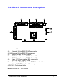
3395U2/U3
64-Bit PCI to Ultra3
Dual Channel
SCSI Host Adapter
User’s Manual
Revision 1.1E
Table of Contents
1.
Using the Host Adapter ........................................................ 1
1.1.
General Description.............................................. 1
1.2.
Features................................................................. 1
Board Connectors Description ............................................. 3
2.
Installing the Host Adapter ................................................... 4
2.1.
2.2.
3.
Board Installation ................................................. 4
Driver Installation................................................. 6
Configuring the Host Adapter ............................................... 7
3.1.
3.2.
When to Configure the Host Adapter ................... 7
Starting the BIOS Configuration Utility............... 7
3.2.1.
Configuration Utility Main Menu ................ 7
3.2.2.
Change Adapter Properties ........................... 8
3.2.3.
Boot Adapter List ....................................... 10
3.2.4.
Global Properties ........................................ 10
3.3.
Exiting the BIOS Configuration Utility ............. 10
4.
Q & A ...................................................................................11
3395U2/U3 User’s Manual
i
For Europe
This drive is in conformity with the EMC directive.
This device complies with Part 15 of the FCC Rules. Operation is subject to
the following two conditions: (1) This device may not cause harmful
interference, and (2) This device must accept any interference received,
including interference that may cause undesired operation.
Federal Communications Commission (FCC) Statement
This equipment has been tested and found to comply with the limits for a
Class B digital device, pursuant to part 15 of the FCC Rules. Those limits are
designed to provide reasonable protection against harmful interference in a
residential installation. This equipment generates, uses and can radiate radio
frequency energy and, if not installed and used in accordance with the
instructions, may cause harmful interference to radio communications.
However, there is no guarantee that interference will not occur in a particular
installation. If this equipment does cause harmful interference to radio or
television reception, which can be determined by turning the equipment off
and on, the user is encouraged to try to correct the interference by one or more
of the following measures:
• Reorient or relocate the receiving antennas.
• Increase the separation between the equipment and receiver.
• Connect the equipment into an outlet on a circlet different from that to
which the receiver is connected.
• Consult the dealer or an experienced radio/TV technician for help.
Warning:
A shielded-type power cord is required in order to meet FCC emission limits
and also to prevent interference to the nearby radio and television reception. It
is essential that only the supplied power cord be used.
Use only shielded cables to connect I/O devices to this equipment.
You are cautioned that changes or modifications not expressly approved by the
party responsible for compliance could void your authority to operate the
equipment.
ii
3395U2/U3 User’s Manual
1. Using the Host Adapter
1.1. General Description
The 3395U2/U3 is the new generation 64-bit PCI to Ultra2/Ultra3 (Ultra160)
Dual Channel SCSI high-speed host adapter board.
The 64-bit PCI bus can provide a maximum of 133*2=266 MB/Sec of bus
signal for power-user’s need.
The dual SCSI channels provide 16-bit Low Voltage Differential (LVD) and
Single-Ended (SE) SCSI solutions for your computer, using only one PCI slot.
This interface can provide a maximum of 80*2=160 MB/Sec for 3395U2 and
160*2=320 MB/Sec for 3395U3 burst transfer rate, and 30 devices connected
capabilities. Which can meet the increasing requirement on the today’s
mass-storage accessing.
The 3395U2/U3 has the ability of downward compatible with legacy devices.
The 32-bit PCI bus, legacy SE Fast/Ultra SCSI devices, narrow or wide, and
the newest Ultra2/Ultra3 SCSI devices, are all supported. These features make
the adapter one of the best choices for the next -generation servers, RAID
subsystems, and workstations system storage solutions.
1.2. Features
l
Full 32-bit or 64-bit DMA bus master, zero wait-state PCI bus provide
high-speed bus signal (133*2=266 MB/Sec max.); PCI specification
revision 2.1 conformed
l
Two separate Ultra2/Ultra3 SCSI channels high-performance interface
data transfer, support 30 devices (80*2=160 MB/Sec for 3395U2 and
160*2=320 MB/Sec for 3395U3 burst transfer rate)
l
Exclusive SureLINK™ domain validation technology verifies Ultra160
link integrity, ensures system operation at Ultra160 speeds, reduces
system downtime, and identifies marginal cabling environments.
l
Complete end-to-end protection of the SCSI I/O—Asynchronous
Information Protection (AIP) safeguards all non-data phases and
augments the cyclic redundancy check (CRC) feature of Ultra160 SCSI.
l
Improved signaling and compatibility—Proven LVDlink™ signaling
capability and SureLINK technology enhance system availability and
manageability.
3395U2/U3 User’s Manual
1
l
16-bit SE/LVD SCSI signal auto-detected, easy supporting for the legacy
SCSI devices
l
Auto/Active SCSI bus termination, need no manual operation
l
Support both 32-bit and 64-bit PCI bus slot, easily adapted for all kinds
of M/B
l
Single I/O Processor chip SYM53C896/53C1010 high-end technology
design from LSI Logic/Symbios
l
Downward compatible with legacy SE Fast/Ultra SCSI devices, narrow
or wide, and the newest Ultra2/Ultra3 SCSI devices
l
One external 68-pin SE/LVD HD connector, two internal 68-pin
SE/LVD connector, one internal 50-pin SE box header, provide
maximum possible devices connection
l
Flash EEPROM BIOS, easy F/W code upgrading
l
NVRAM with easy operating BIOS configuration utility for board
configuration information changing and storing
l
Storage Device Management System (SDMS) software from original
design of LSI Logic/Symbios
l
SCSI activity LED for each channel
l
PCI board dimensions, approximately 6.85 x 3.8 inches
l
Universal 64-bit PCI card edge connector
2
3395U2/U3 User’s Manual
1.3. Board Connectors Description
Fig. 1.1 3395U2/U3 Board Connectors
J2: External 68-pin SE/LVD HD connector
J4/J6 :Internal 68-pin SE/LVD connector
J3: Internal 50-pin SE box header
*
J2/J6 share the same SCSI channel 0
J3/J4 share the same SCSI channel 1
J5: 4-pin SCSI Busy status LED connector
(Pin-1/4: High, Pin-2/3: Low)
*
Two sets of 3 LEDs for each SCSI channel status
Active, LVD, SE (under J5 from top)
JP2/3/J7: Factory use only
Board Size: 6.85 x 3.8 inches
3395U2/U3 User’s Manual
3
2. Installing the Host Adapter
This chapter provides instructions on how to install the Host Adapter.
2.1. Board Installation
Step 1.
Ground yourself before removing this host adapter board.
Step 2.
Switch off and unplug the system.
Step 3.
Locate and install the board to one of the available 64-bit PCI
bus-master slot. A 32-bit slot can be used but full performance
requires a 64-bit slot.
Fig. 2.1 Adapter Board Insertion
4
3395U2/U3 User’s Manual
Step 4.
Properly connect the SCSI devices. Make sure no SCSI-ID
conflicting and termination at bus both end. SCSI ID 7 is the preset host
adapter setting
Fig. 2.2 SCSI devices installation
* Note the legacy devices (Fast/Ultra) combined connected with LVD devices
on the same bus will slow-down the throughput. Please install these devices on
one channel and other legacy-free(LVD) devices on the other channel.
3395U2/U3 User’s Manual
5
Step 5.
Connect the 4-pin SCSI Busy status LED cable as need.
Fig. 2.3 SCSI Busy status LED cable Insertion
Step 6.
Close and power-up the system.
Step 7.
Configure the BIOS if necessary.
Step 8.
Install the needed driver set.
Step 9.
Installation complete, restart the system.
2.2. Driver Installation
Please refer to the driver CD provided for detailed information on each
different Operation System installation.
6
3395U2/U3 User’s Manual
3. Configuring the Host Adapter
This chapter discusses how to change configuration settings and includes these
topics:
l
Section 3.1, “When to Configure the Host Adapter,”
l
Section 3.2, “Starting the BIOS Configuration Utility,”
l
Section 3.3, “Exiting the BIOS Configuration Utility,”
3.1. When to Configure the Host Adapter
In most cases you should not need to change the default configuration of your
host adapter. You may decide to alter these default values if there is a conflict
between device settings, or if you need to optimize system performance.
3.2. Starting the BIOS Configuration Utility
You can see the version number of your SCSI BIOS in a banner displayed on
your computer monitor during boot. If the utility is available, the following
message appears on your monitor:
Press Ctrl-C to start Symbios Configuration Utility...
This message remains on your screen for about five seconds, giving you time
to start the utility. If you decide to press “Ctrl-C”, the message changes to:
Please wait, invoking Symbios Configuration Utility...
After a brief pause, your computer monitor displays the Main Menu of the
SCSI BIOS Configuration Utility.
3.2.1.
Configuration Utility Main Menu
When you start the SCSI BIOS Configuration Utility, the Main Menu appears.
This menu displays a list of up to four PCI to SCSI host adapters in your
system and information about each of them.
3395U2/U3 User’s Manual
7
The Main Menu looks like this:
Symbios PCI SCSI Configuration Utility Version PCI-4.16.00
<Boot Adapter List> <Global Properties>
LSI Logic Host Bus Adapters
Adapter
PCI Dev/ Port
Bus Func Number
IRQ NVM Boot
Order
Symbios
Control
11
11
Enabled
Enabled
<SYM53C1010 2
<SYM53C1010 2
48> C800
49> C800
F1=Help
ESC=Abort/Exit
ArrowKeys=Select Item
Home/End=Select Item
Yes
Yes
0
1
-/+=Change[Item]
Enter=Execute[Item]
Each Adapter properties, Boot Adapter List, and Global Properties can be
reached from this window. They are described in details below.
3.2.2.
Change Adapter Properties
The change adapter properties allows you to change the properties of a host
adapter and all SCSI devices attached to it. If you made any change, the
change takes place after a reboot.
Symbios PCI SCSI Configuration Utility Version
Adapter
Properties
Adapter
PCI
Dev/
Bus
Func
<SYM53C1010 2
48>
Device Properties
SCSI Parity
Host SCSI ID
SCSI Bus Scan Order
Removable Media Support
CHS Mapping
Spin-up Delay (Secs)
Secondary Cluster Server
Termination Control
<Restore Defaults>
F1=Help
ESC=Abort/Exit
ArrowKeys=Select Item
Home/End=Select Item
PCI-4.16.00
[Yes]
[7]
[Low to high(0..Max)]
[None]
[SCSI PnP Mapping]
[2]
[No]
[Auto]
-/+=Change[Item]
Enter=Execute[Item]
SCSI Parity -The PCI to SCSI host adapters always generate parity, but some
older SCSI devices do not. Therefore, you are offered the option of disabling
parity checking.
8
3395U2/U3 User’s Manual
Note: When disabling parity checking, it is also necessary to disable
disconnects for all devices, as parity checking for the reselection phase is not
disabled. If a device does not generate parity, and it disconnects, the I/O never
completes because the reselection never completes.
Host SCSI ID -In general, it is suggested that you do not change your host
adapter ID from the default value of 7, as this gives it the highest priority on
the SCSI bus.
SCSI Bus Scan Order -This option allows you to tell the SCSI BIOS and
device drivers to scan the SCSI bus from low to high (0 to max) SCSI ID, or
from high to low (max to 0) SCSI ID. If you have more than one device on the
SCSI bus, changing the scan order changes the order in which drive letters are
assigned by the system. Drive order may be reassigned differently in systems
supporting the BIOS Boot Specification (BBS).
Note: This scan order option may conflict with operating systems that
automatically assign a drive order.
Removable Media Support -This option defines the removable media
support for a specific drive. When this option is selected, a window appears
with three choices:
l None
l Boot Drive Only
l With Media Installed
None indicates there is no removable media support whether the drive is
selected in BBS as being first, or first in scan order in non-BBS.
Boot Drive Only provides removable media support for a removable hard
drive if it is first in the scan order.
With Media Installed provides removable media support wherever the
drive(s) actually resides.
CHS Mapping -This option defines the cylinder head sector (CHS) values
that will be mapped onto a disk without pre-existing partitioning information.
SCSI Plug and Play Mapping is the default value.
To support interchange with non-compatible systems, there is another option
that can be selected by choosing CHS Mapping and then change to: ”Alternate
CHS Mapping”
Note: Neither of these options will have any effect after the disk has been
partitioned with the FDISK command.
3395U2/U3 User’s Manual
9
3.2.3.
Boot Adapter List
The adapter boot order allows you to set the order in which host adapters will
boot when you have more than one host adapter in your system. While the
maximum capacity is 32 adapters, only 0 through 3 can be assigned a boot
order in the list.
Symbios PCI SCSI Configuration Utility Version PCI-4.16.00
<Boot Adapter List>
Insert=Add an Adapter
Delete=Remove an Adapter
Adapter
PCI
Bus
<SYM53C1010 2
<SYM53C1010 2
Dev/ Boot
Func Order
Current
Status
Next
Boot
48> [0]
49> [1]
On
On
[On]
[On]
Hit Insert to Select an adapter from this list
<SYM53C1010
0 48>
<SYM53C1010
0 49>
3.2.4.
Global Properties
The global properties can be changed from the window at next.
Symbios PCI SCSI Configuration Utility Version PCI-4.16.00
<Global Properties>
Pause when Boot Alert Displayed
Boot Information Display Mode
Negotiate with devices
Video Mode
[No]
[Verbose]
[Supported]
[Color]
3.3. Exiting the BIOS Configuration Utility
Since some changes only take effect after your system reboots, it is important
that you exit this configuration utility properly. Return to the Main Menu and
exit. If you reboot the system without properly exiting the utility, some
changes may not take effect.
10
3395U2/U3 User’s Manual
4. Q & A
Q: What are the features of the different SCSI applications?
A: SCSI-1/2 is 5MB/Sec 8-bit bus. SCSI-2 Fast is 10MB/Sec 8-bit bus. SCSI-2
Fast Wide is 20MB/Sec 16-bit bus. Ultra SCSI is 20MB/Sec 8-bit bus. Ultra
Wide SCSI is 40MB/Sec 16-bit bus. Ultra2 Wide SCSI is 80MB/sec 16-bit bus.
Ultra3 (Ultra160) Wide SCSI is 160MB/sec 16-bit bus.
Q: What is the maximum cable length can be used on my host adapter?
A: The maximum total length should include internal plus external cables, and
is affected by the status and quality of the environment. The number of devices
on the bus and the maximum desired bandwidth determines it. The total cable
length limits the maximum bandwidth due to bus attenuation, impedance of the
devices, and propagation delay of the signals. Qualified cables should be used
to assure the good data transfer.
In general, the maximum cable lengths in different applications are:
SCSI-1/2 (5MB/Sec) 6 meters (18ft)
SCSI-2 fast/wide, Ultra (20MB/Sec) 3 meters (9 ft)
Ultra Wide (40MB/Sec) 1.5 meters (>4 devices)
Ultra Wide (40MB/Sec) 3 meters (<4 devices)
Ultra2 Wide (80MB/Sec) 12 meters (>2 devices)
Ultra3 Wide (160MB/Sec) 12 meters (>2 devices)
Q: Can I install the adapter on a 32-bit PCI slot?
A: A 32-bit slot can be used but only half of the PCI bus performance is got
compared with 64-bit bus. To get full performance requires a 64-bit slot.
Q: Can I connect Ultra2 devices with Ultra3 devices on the same channel?
A: Yes, these two kinds of devices can be connected on the same channel. They
are both using the compatible LVD signal. Ultra2 (Wide) signal data-rate is
still 80 MB/Sec, while Ultra3 (Wide) signal data-rate is still 160 MB/Sec.
There is no performance penalty.
3395U2/U3 User’s Manual
11
Q: Can I connect legacy devices with Ultra2/3 devices on the same channel?
A: The legacy devices (Fast/Ultra SE) combined connected with LVD devices
on the same bus is possible but will slow-down the throughput. All data were
transferred as the legacy devices type of bus. Please install these devices on
one channel and other legacy-free(LVD) devices on the other channel. You
can check the LEDs under J5 to get the current bus type (SE/LVD) status.
Q: What is the difference between SE (Single Ended) and LVD (Low Voltage
Differential) interfaces?
A: Single-ended (SE) interface uses one line for each data or command/status
signal, with a corresponding ground line. Voltage is carried only on the signal
line. The possible transfer distance is short and noisy.
Low Voltage Differential(LVD) interface uses signal transmitters and
receivers to drive the signal. The signal is split into positive and negative
parts and transmitted over cable pairs. Voltage is carried on both data lines.
The signal is re-combined at the receiving side. The possible transfer distance
is higher and with good signal noise immunity. It is strongly recommended for
the high bandwidth data transfer.
Q: What is SCSI Termination?
A: SCSI Termination is the electrical resistors (terminators) installed in the
devices at each end of the bus to meet the signal electrical specification. Any
devices in the middle of the bus should not terminate. The host adapter is
Auto/Active terminated to guaranty the proper and good data transfer. No
manual operation is need. While we recommend using the external terminator
on the bus to achieve easy maintenance and hot plugging of the devices.
12
3395U2/U3 User’s Manual