1
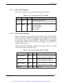
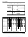
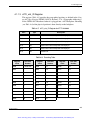
Artisan Technology Group is your source for quality
new and certified-used/pre-owned equipment
• FAST SHIPPING AND
DELIVERY
• TENS OF THOUSANDS OF
IN-STOCK ITEMS
• EQUIPMENT DEMOS
• HUNDREDS OF
MANUFACTURERS
SUPPORTED
• LEASING/MONTHLY
RENTALS
• ITAR CERTIFIED
SECURE ASSET SOLUTIONS
SERVICE CENTER REPAIRS
Experienced engineers and technicians on staff
at our full-service, in-house repair center
WE BUY USED EQUIPMENT
Sell your excess, underutilized, and idle used equipment
We also offer credit for buy-backs and trade-ins
www.artisantg.com/WeBuyEquipment
InstraView REMOTE INSPECTION
LOOKING FOR MORE INFORMATION?
Visit us on the web at www.artisantg.com for more
information on price quotations, drivers, technical
specifications, manuals, and documentation
SM
Remotely inspect equipment before purchasing with
our interactive website at www.instraview.com
Contact us: (888) 88-SOURCE | [email protected] | www.artisantg.com
USPIIe-cPCI Software Manual
Version 1.0 — January 2003
Themis Computer—Americas and Pacific Rim
3185 Laurelview Court
Fremont, CA 94538
Phone (510) 252-0870
Fax (510) 490-5529
World Wide Web http://www.themis.com
Themis Computer—Rest of World
5 Rue Irene Joliot-Curie
38320 Eybens, France
Phone +33 476 14 77 80
Fax +33 476 14 77 89
Artisan Technology Group - Quality Instrumentation ... Guaranteed | (888) 88-SOURCE | www.artisantg.com
Copyright © 2003 Themis Computer, Inc.
ALL RIGHTS RESERVED. No part of this publication may be reproduced in any form, by
photocopy, microfilm, retrieval system, or by any other means now known or hereafter invented without
the prior written permission of Themis Computer.
The information in this publication has been carefully checked and is believed to be accurate. However,
Themis Computer assumes no responsibility for inaccuracies. Themis Computer retains the right to
make changes to this publication at any time without prior notice. Themis Computer does not assume
any liability arising from the application or use of this publication or the product(s) described herein.
RESTRICTED RIGHTS LEGEND: Use, duplication, or disclosure by the United States Government
is subject to the restrictions set forth in DFARS 252.227-7013 (c)(1)(ii) and FAR 52.227-19.
TRADEMARKS
THEMIS® is a registered trademark of Themis Computer, Inc.
SOLARIS™ is a trademark of Sun Microsystems
SPARC® and UltraSPARC® are registered trademarks of SPARC International
All other trademarks or registered trademarks used in this publication are the property of their
respective owners.
Themis Customer Support
North America, South America, and Pacific Rim
Telephone:
Fax:
E-mail:
Web Site:
510-252-0870
510-490-5529
[email protected]
http://www.themis.com
USPIIe-cPCI Software Manual
January 2003
Part Number: 110553-023
Artisan Technology Group - Quality Instrumentation ... Guaranteed | (888) 88-SOURCE | www.artisantg.com
USPIIe-cPCI Software Manual
Version Revision History
Version 1.0.......................................................................................January 2003
iii
Themis Computer
Artisan Technology Group - Quality Instrumentation ... Guaranteed | (888) 88-SOURCE | www.artisantg.com
USPIIe-cPCI Software Manual
iv
Themis Computer
Artisan Technology Group - Quality Instrumentation ... Guaranteed | (888) 88-SOURCE | www.artisantg.com
Table of Contents
How to Use This Manual ...................................................................................................... ix
1. USPIIe-cPCI Address Map .......................................................................................... 1-1
1.1
Introduction ............................................................................................................ 1-1
1.2
USPIIe-cPCI Address Map .................................................................................... 1-1
1.3
PCI Address Map ................................................................................................... 1-2
1.4
List of PCI devices ................................................................................................. 1-3
1.5
Physical Memory Address Range .......................................................................... 1-4
1.6
UltraSPARC-IIe PCI Control and Status Registers ............................................... 1-4
1.7
Advanced PCI Bridge (APB) Configuration Space Registers ............................. 1-10
1.8
PCI Bridge 21154 Registers ................................................................................ 1-12
1.9
Ultra Fast/Wide SCSI Controller (SYMBIOS SYM53C896) ............................. 1-13
2. USPIIe-cPCI Interrupts ............................................................................................... 2-1
2.1
Overview ................................................................................................................ 2-1
2.2
Mondo Dispatch Overview .................................................................................... 2-2
2.3
UltraSPARC-IIe Interrupt Registers ...................................................................... 2-3
2.3.1 Interrupt Mapping Registers ...................................................................... 2-3
2.3.2 Interrupt Vector Data Register ................................................................... 2-3
2.3.3 Clear Interrupt Register ............................................................................. 2-5
2.4
Interrupt Level Mapping ........................................................................................ 2-5
3. Temperature Monitoring .............................................................................................. 3-1
3.1
Temperature Monitoring ........................................................................................ 3-1
4. PLD Register Set ........................................................................................................... 4-1
4.1
PLD Registers ........................................................................................................ 4-1
4.1.1 PLD Register Description .......................................................................... 4-1
v
Themis Computer
Artisan Technology Group - Quality Instrumentation ... Guaranteed | (888) 88-SOURCE | www.artisantg.com
USPIIe-cPCI Software Manual
4.1.1.1
4.1.1.2
4.1.1.3
4.1.1.4
4.1.1.5
4.1.1.6
4.1.1.7
4.1.1.8
4.1.1.9
4.1.1.10
4.1.1.11
4.1.1.12
PLD_ID/rev Register .................................................................. 4-3
Flash_status Register .................................................................. 4-3
cPCI_slot_ID Register ................................................................ 4-5
Patch_status Register (Themis-qualified personnel only) .......... 4-6
Test_status Register (Themis-qualified personnel only) ............ 4-6
Voltage_status Register .............................................................. 4-7
TTY/KBM_config Register ........................................................ 4-8
SCSI_A_status Register .............................................................. 4-8
Misc_status Register ................................................................... 4-9
2-Level Watchdog Registers ..................................................... 4-10
Semaphore_Status Register ...................................................... 4-10
Semaphore_Request1 Register ................................................. 4-11
5. Themis USPIIe-cPCI Software .................................................................................... 5-1
5.1
Introduction ............................................................................................................ 5-1
5.2
SUN OBP (OpenBoot PROM) .............................................................................. 5-1
5.2.1 OBP Environment Variables ..................................................................... 5-2
5.2.2 Updating Flash PROMs ............................................................................. 5-5
5.2.3 USPIIe-cPCI OBP Device aliases .............................................................. 5-7
5.3
SUN Solaris ........................................................................................................... 5-7
Index............................................................................................................................... Index-1
vi
Themis Computer
Artisan Technology Group - Quality Instrumentation ... Guaranteed | (888) 88-SOURCE | www.artisantg.com
Table of Contents
List of Figures
Figure 2-1
Interrupt Logic. ................................................................................................ 2-2
List of Tables
Table 1-1
UltraSPARC-IIe Address Map ........................................................................ 1-1
Table 1-2
Physical Address Space to PCI Space ............................................................ 1-2
Table 1-3
List of PCI Devices.......................................................................................... 1-3
Table 1-4
Physical Memory Address Range.................................................................... 1-4
Table 1-5
CSR Register Address Space ........................................................................... 1-4
Table 1-6
APB Configuration Space Registers.............................................................. 1-10
Table 1-7
PCI Bridge Registers ..................................................................................... 1-12
Table 1-8
SCSI Controller Registers.............................................................................. 1-13
Table 2-1
Interrupt Mapping register definition .............................................................. 2-3
Table 2-2
Interrupt Receive Data Register....................................................................... 2-4
Table 2-3
Clear Interrupt Register ................................................................................... 2-5
Table 2-4
Interrupt level mapping.................................................................................... 2-5
Table 4-1
PLD Register Address Map ............................................................................. 4-2
Table 4-2
PLD_ID/rev Register 0x1FF.F120.0000 ......................................................... 4-3
Table 4-3
Flash_status Register 0x1FF.F120.0002.......................................................... 4-3
Table 4-4
Flash PROM/Rombo Address Mapping .......................................................... 4-4
Table 4-5
cPCI_slot_ID Register 0x1FF.F120.0003 ....................................................... 4-5
Table 4-6
Encoding Table ................................................................................................ 4-5
Table 4-7
Patch_status Register 0x1FF.F120.0005 ......................................................... 4-6
Table 4-8
Test_status Register 0x1FF.F120.0006 ........................................................... 4-6
Table 4-9
Voltage_status Register 0x1FF.F120.0007...................................................... 4-7
Table 4-10
TTY/KBM_config Register 0x1FF.F120.0008 ............................................... 4-8
Table 4-11
SCSI_A_status Register 0x1FF.F120.0009 ..................................................... 4-9
vii
Themis Computer
Artisan Technology Group - Quality Instrumentation ... Guaranteed | (888) 88-SOURCE | www.artisantg.com
USPIIe-cPCI Software Manual
Table 4-12
Misc_status Register 0x1FF.F120.000a........................................................... 4-9
Table 4-13
Semaphore_Status Register 0x1FF.F120.00F0 ............................................. 4-11
Table 4-14
Semaphore_Request1 register 0x1FF.F120.00F1.......................................... 4-11
Table 5-1
OBP Environment Variables ........................................................................... 5-2
Table 5-2
List of OBP aliases .......................................................................................... 5-8
viii
Themis Computer
Artisan Technology Group - Quality Instrumentation ... Guaranteed | (888) 88-SOURCE | www.artisantg.com
How to Use This Manual
Introduction
Themis Computer’s USPIIe-cPCI is a UltraSPARC-IIe-based single-board computer
that operates at up to 650 MHz with up to 2 GB of custom memory. The USPIIecPCI is designed with a 6RU form factor and resides in a cPCI backplane. I/O from
the front faceplate includes two SCSI, two serial, a PS/2 keyboard/mouse or dual
USB, and two Ethernet ports. Additional connections are available through a userinstalled optional PMC Module mounted directly on the USPIIe-cPCI Baseboard
In addition, a 1-slot wide Rear Transition Board is available for the USPIIe-cPCI
that mounts behind the cPCI backplane and provides I/O connections for two SCSI,
one parallel, four serial, two USB, and four audio ports. Themis has also developed
custom software that enables software programmers to effectively use the powerful
features of high-speed PCI and cPCI architecture.
[See the USPIIe-cPCI Hardware Manual, Themis Part Number 110553-022, for
more information.]
Intended Audience
The custom software containing programs, documentation, and packaging, is targeted for various software users:
• System Administrators who install the software and perform the necessary
software configuration.
ix
Themis Computer
Artisan Technology Group - Quality Instrumentation ... Guaranteed | (888) 88-SOURCE | www.artisantg.com
USPIIe-cPCI Software Manual
• Users who perform day-to-day operations on USPIIe-cPCI systems.
• Application programmers who write user-level programs to access cPCI-bus
interface devices through the built-in software.
• System programmers/device-driver writers who develop kernel-level device
drivers for cPCI devices.
Some functions overlap one another. The basic concepts required for many of these
functions are common. This manual is structured around the basic concepts of using
a cPCI bus system.
In Case Of Difficulties
If the USPIIe-cPCI does not behave as described or if you encounter difficulties
installing or configuring the board, please call Themis Computer technical support at
+1 (510) 252-0870, fax your questions to +1 (510) 490-5529, or e-mail to [email protected]. You can also contact us via our web site: http://www.themis.com.
UNIX Commands
This document may not contain information on basic UNIX® commands and procedures such as shutting down the system, booting the system, and configuring
devices.
See one or more of the following for this information:
• Solaris Handbook for Sun Peripherals, which contains SolarisTM software commands
• AnswerBookTM on-line documentation for the Solaris software environment
• Other software documentation that you received with your system
x
Themis Computer
Artisan Technology Group - Quality Instrumentation ... Guaranteed | (888) 88-SOURCE | www.artisantg.com
How to Use This Manual
Shell Prompts
Shell Prompts
Shell
Prompt
C shell
machine_name%
C shell superuser
machine_name#
Bourne shell and Korn shell
$
Bourne shell and Korn shell superuser
#
Website Information
Themis Computer corporate and product information may be accessed on the World
Wide Web by browsing the website http://www.themis.com.
Notes, Cautions, Warnings, and Sidebars
The following icons and formatted text are included in this document for the reasons
described:
A note provides additional information concerning the procedure or action
being described that may be helpful in carrying out the procedure or action.
Note:
A caution describes a procedure or action that may result in injury to the
operator or equipment damage. This may involve—but is not restricted to—heavy
equipment or sharp objects. To reduce the risk, follow the instructions accompanying this symbol.
Caution:
xi
Themis Computer
Artisan Technology Group - Quality Instrumentation ... Guaranteed | (888) 88-SOURCE | www.artisantg.com
USPIIe-cPCI Software Manual
A warning describes a procedure or action that may cause injury to the
operator or equipment as a result of hazardous voltages. To reduce the risk of electrical shock and danger, follow the instructions accompanying this symbol.
Warning:
A “sidebar” adds detail to the section within which it is placed,
but is not absolutely vital to the description or procedure of the section.
Sidebar:
Your Comments are Welcome
We are interested in improving our documentation and welcome your comments and
suggestions. You can email your comments to us at [email protected].
Please include the document part number in the subject line of your email.
xii
Themis Computer
Artisan Technology Group - Quality Instrumentation ... Guaranteed | (888) 88-SOURCE | www.artisantg.com
1
Operation
Section
Chapter
1
USPIIe-cPCI Address Map
1.1
Introduction
This chapter provides detailed descriptions of the address maps and register address
locations for the Themis Computer USPIIe-cPCI single-board computer.
1.2
USPIIe-cPCI Address Map
The UltraSPARC-IIe CPU used on the USPIIe-cPCI divides its physical address
space among:
• DRAM
• PCI, that is further subdivided by three PCI segments into PCI A, B, and C bus
spaces
Table 1-1. UltraSPARC-IIe Address Map
Address Range in PA <40:0>
Size
Port Addressed
Access type
0x000.0000.0000
0x000.7FFF.FFFF
2 GB
SDRAM Main Memory
Cacheable
0x000.8000.0000
0x000.FFFF.FFFF
2 GB
Reserved
Cacheable
0x001.0000.0000
0x007.FFFF.FFFF
—
Reserved
Cacheable
0x008.0000.0000
0x1FD.FFFF.FFFF
—
Reserved
Non-Cacheable
1-1
Themis Computer
Artisan Technology Group - Quality Instrumentation ... Guaranteed | (888) 88-SOURCE | www.artisantg.com
USPIIe-cPCI Software Manual
Table 1-1. UltraSPARC-IIe Address Map (Continued)
Address Range in PA <40:0>
0x1FE.0000.0000
1.3
0x1FF.FFFF.FFFF
Size
8 GB
Port Addressed
Access type
Processor Subsystems
(PCI, memory, clock
control, GP outputs,
and ECU)
Non-Cacheable
PCI Address Map
The UltraSPARC-IIe CPU directly interfaces the primary PCI bus. The PCI Bus
mapping as seen from the CPU is given in Table 1-2.
Table 1-2. Physical Address Space to PCI Space
PCI Address
Space
PA[40:0]
Configuration Read
Non Cacheable
write (any)
(may also be Special
0x1FE.0200.0000-
NCa read (any)
I/O Read
0x1FE.02FF.FFFF
NC write (any)
I/O Write
0x1FE.0100.0000-
Space
0x1FE.01FF.FFFF
Don’t Use
PCI Commands Generated
Non Cacheable
read (any)
PCI Configuration
PCI Bus I/O Space
CPU Commands
Supported
0x1FE.0300.00000x1FE.FFFF.FFFF
Configuration Write
Cycle)
May wrap to
--
Configuration or I/O
Space behavior
NC read (4 byte)
Memory Read
NC read (8 byte)
Memory Read Multiple
PCI Bus Memory
0x1FF.0000.0000-
NC Block read
Memory Read Line
Space
0x1FF.FFFF.FFFF
NC write
Memory Write
NC Block write
Memory Write
NC Instruction fetch
Memory Read
a—NC = Non-Cacheable.
1-2
Themis Computer
Artisan Technology Group - Quality Instrumentation ... Guaranteed | (888) 88-SOURCE | www.artisantg.com
1—USPIIe-cPCI Address Map
List of PCI devices
1.4
List of PCI devices
Table 1-3 lists all on-board PCI devices that are attached to the PCI bus interface.
This does not include the PMC Module (expansion card) that may be plugged into
the USPIIe-cPCI Baseboard.
Table 1-3. List of PCI Devices
Bus
Number
Device
Number
Function
Number
Vendor
ID
Device ID
Configuration
space offseta
0
0
0
CPU PCI Bus Module
0x108e
0xa001
0
0
1
0
APB chip (Bus A)
0x108e
0x5000
0x800
0
1
1
APB chip (Bus B)
0x108e
0x5000
0x900
0
2
0
Intel PCI-PCI Bridge
(Bus C)
0x8086
0xb154
0x1000
1
C
0
PCIO-Rio (A)
(Ebus 1)
0x108e
0x1100
0x16000
1
C
1
PCIO-Rio
(Ethernet A)
0x108e
0x1101
0x16100
2
8
0
Symbios SCSI
Controller (Port A)
0x1000
0xb
0x24000
2
8
1
Symbios SCSI
Controller (Port B)
0x1000
0xb
0x24100
1
3
0
AcerLabs Super I/O
PMC-I2C
0x10bg
0x7101
0x11800
1
7
0
AcerLabs Southbridge
0x10bg
0x1533
0x13800
1
8
0
AcerLabs Audio
0x10bg
0x5451
0x14000
1
d
0
AcerLabs IDE
0x10bg
0x5229
0x16800
1
5
0
RIO (B) eBus
0x108e
0x1100
0x12800
1
5
1
RIO (B) Ethernet
0x108e
0x1100
0x12900
PCI Device
a—This offset is derived from bus #, device #, function #, as specified in PCI specs. To find the full CPU physical address, you
need to add the PCI configuration space base address 0x1FE.0100.0000. To examine the configuration header under OBP, use
the “sph” command. For example: “ok 21800 sph” will display the DEC PCI-PCI bridge configuration header.
1-3
Themis Computer
Artisan Technology Group - Quality Instrumentation ... Guaranteed | (888) 88-SOURCE | www.artisantg.com
USPIIe-cPCI Software Manual
1.5
Physical Memory Address Range
Table 1-4. Physical Memory Address Range
Memory
Bank/RASa
Address Range
1/0B
0x0000.0000 to 0x07FF.FFFF
2/0T
0x2000.0000 to 0x27FF.FFFF
3/1B
0x0800.0000 to 0x0FFF.FFFF
4/1T
0x2800.0000 to 0x2FFF.FFFF
5/2B
0x1000.0000 to 0x13FF.FFFF
6/2T
0x3000.0000 to 0x37FF.FFFF
7/3B
0x1800.0000 to 0x1FFF.FFFF
8/3T
0x3800.0000 to 0x3FFF.0000
a—128MB/RAS. One bank is equal to 128Mbytes (10bit column mode)
1.6
UltraSPARC-IIe PCI Control and Status
Registers
This table lists the UltraSPARC-IIe registers that controls the PCI Bus and the interrupts management.
Table 1-5. CSR Register Address Space
Physical Address
Register
Access size
DMA Error Registers: The following USPIIe-cPCI CPU registers control DMA activity (i.e PCI activity not generated by the CPU). Please refer to Sun’s UltraSPARC-IIe
manual for details.
1-4
0x1FE.0000.0030
DMA UE AFSR
8 bytes
0x1FE.0000.0038
DMA UE/CE AFAR
8 bytes
Themis Computer
Artisan Technology Group - Quality Instrumentation ... Guaranteed | (888) 88-SOURCE | www.artisantg.com
1—USPIIe-cPCI Address Map
UltraSPARC-IIe PCI Control and Status Registers
Table 1-5. CSR Register Address Space (Continued)
Physical Address
Register
Access size
0x1FE.0000.0040
DMA CE AFSR
8 bytes
0x1FE.0000.0048
CMD UE/CE AFAR (aliases to
0x1FE.0000.0038)
8 bytes
IOMMU Registers: The following CPU registers controls the IOMMU. Please refer
to Sun’s UltraSPARC-IIe manual for details.
0x1FE.0000.0200
IOMMU Control Register
8 bytes
0x1FE.0000.0208
IOMMU TSB Base address Register
8 bytes
0x1FE.0000.0210
IOMMU FlushRegister
8 bytes
Interrupt Registers: The following CPU registers are the Interrupt Mapping Registers. There is one such register for each Interrupt source. They are programmed with
the INO (Interrupt Number Offset) for that interrupt. The INO will be used to retrieve
the interrupt handler for that IRQ source. These registers also contain a VALID bit
that will enable the related interrupt (See Chapter 5, “USPIIe Interrupts”.)
0x1FE.0000.0C00
PCI Bus A Slot 0 Int Mapping register
8 bytes
0x1FE.0000.0C08
PCI Bus A Slot 1Int Mapping register
8 bytes
0x1FE.0000.0C10
PCI Bus A Slot 2 Int Mapping register
8 bytes
0x1FE.0000.0C18
PCI Bus A Slot 3Int Mapping register
8 bytes
0x1FE.0000.0C20
PCI Bus B Slot 0 Int Mapping register
8 bytes
0x1FE.0000.0C28
PCI Bus B Slot 1Int Mapping register
8 bytes
0x1FE.0000.0C30
PCI Bus B Slot 2 Int Mapping register
8 bytes
0x1FE.0000.0C38
PCI Bus B Slot 3Int Mapping register
8 bytes
0x1FE.0000.1000
SCSI In Mapping register
8 bytes
0x1FE.0000.1008
Ethernet Int Mapping register
8 bytes
0x1FE.0000.1010
Parallel port Int Mapping Register
8 bytes
0x1FE.0000.1018
Audio Record Int Mapping Register
8 bytes
0x1FE.0000.1020
Audio Playback Int Mapping Register
8 bytes
0x1FE.0000.1028
Power fail Int Mapping Register
8 bytes
0x1FE.0000.1030
Keyboard/mouse Int Mapping Register
8 bytes
0x1FE.0000.1038
Floppy Int mapping register
8 bytes
1-5
Themis Computer
Artisan Technology Group - Quality Instrumentation ... Guaranteed | (888) 88-SOURCE | www.artisantg.com
USPIIe-cPCI Software Manual
Table 1-5. CSR Register Address Space (Continued)
Physical Address
Register
Access size
0x1FE.0000.1040
Space HW Int Mapping Register
8 bytes
0x1FE.0000.1048
Keyboard Int Mapping register
8 bytes
0x1FE.0000.1050
Mouse Int mapping Register
8 bytes
0x1FE.0000.1058
Serial Int Mapping Register
8 bytes
0x1FE.0000.1070
DMA UE Int Mapping Register
8 bytes
0x1FE.0000.1078
DMA CE Int Mapping Register
8 bytes
0x1FE.0000.1080
PCI Error Int Mapping Register
8 bytes
0x1FE.0000.1098
On Board Graphic Int Mapping Register
(also mapped at 0x1FE.0000.6000)
8 bytes
0x1FE.0000.10A0
Expansion UPA64 Int mapping register
Interrupt clear registers:
0x1FE.0000.1400 to
PCI bus A slot 0 clear Int registers
8 bytes
PCI Bus A slot 1 clear registers
8 bytes
PCI Bus A slot 2 clear Int registers
8 bytes
PCI Bus A slot 3 clear Int register
8 bytes
PCI bus B slot 0 clear Int registers
8 bytes
PCI Bus B slot 1 clear registers
8 bytes
PCI Bus B slot 2 clear Int registers
8 bytes
PCI Bus B slot 3 clear Int register
8 bytes
0x1FE.0000.0180
SCSI clear Int register
8 bytes
0x1FE.0000.1808
Ethernet clear Int register
8 bytes
0x1FE.0000.1418
0x1FE.0000.1420 to
0x1FE.0000.1438
0x1FE.0000.1440 to
0x1FE.0000.1458
0x1FE.000.1460 to
0x1FE.0000.1478
0x1FE.0000.1480 to
0x1FE.0000.1498
0x1FE.0000.14A0 to
0x1FE.0000.14B8
0x1FE.0000.14C0 to
0x1FE.0000.14D8
0x1FE.0000.14E0 to
0x1FE.0000.14D8
1-6
Themis Computer
Artisan Technology Group - Quality Instrumentation ... Guaranteed | (888) 88-SOURCE | www.artisantg.com
1—USPIIe-cPCI Address Map
UltraSPARC-IIe PCI Control and Status Registers
Table 1-5. CSR Register Address Space (Continued)
Physical Address
Register
Access size
0x1FE.0000.1810
Parallel port clear Int register
8 bytes
0x1FE.0000.1818
Audio record clear Int register
8 bytes
0x1FE.0000.1820
Audio Playback clear Int register
8 bytes
0x1FE.0000.1828
Power fail clear Int register
8 bytes
0x1FE.0000.1830
Keyboard / mouse clear Int register
8 bytes
0x1FE.0000.1838
Floppy clear Int register
8 bytes
0x1FE.0000.1840
Spare HW clear Int register
8 bytes
0x1FE.0000.1848
Keyboard clear Int register
8 bytes
0x1FE.0000.1858
Serial clear Int register
8 bytes
0x1FE.0000.1870
DMA UE clear Int register
8 bytes
0x1FE.0000.1878
DMA CE clear Int register
8 bytes
0x1FE.0000.1880
PCI error clear Int register
8 bytes
0x1FE.0000.1C20
PCI DMA write synchronization register
8 bytes
0x1FE.0000.2000
PCI control / status register
8 bytes
0x1FE.0000.2010
PCI PIO write AFSR
8 bytes
0x1FE.0000.2018
PCI PIO write AFAR
8 bytes
0x1FE.0000.2020
PCI diagnostic register
8 bytes
0x1FE.0000.2028
PCI target address space register
8 bytes
PCI buffer diag access
56 bytes
DMA buffer diag access
56 bytes
0x1FE.0000.51C0
DMA buffer diag access (72:64)
8 bytes
0x1FE.0000.6000
On-board graphics Int Mapping register
(also mapped at 0x1FE.0000.1098)
8 bytes
0x1FE.0000.8000
Expansion UPA64S Int mapping register
(also mapped at 0x1FE.0000.10A0)
8 bytes
0x1FE.0000.5000 to
0x1FE.0000.5038
0x1FE.0000.5100 to
0x1FE.0000.5138
1-7
Themis Computer
Artisan Technology Group - Quality Instrumentation ... Guaranteed | (888) 88-SOURCE | www.artisantg.com
USPIIe-cPCI Software Manual
Table 1-5. CSR Register Address Space (Continued)
Physical Address
Register
Access size
0x1FE.0000.A400
IOMMU virtual address diag register
8 bytes
0x1FE.0000.A408
IOMMU tag compare diag
8 bytes
0x1FE.0000.A580 to
0x1FE.0000.A5FF
0x1FE.0000.A600 to
0x1FE.0000.A67F
IOMMU tag details
128 bytes
IOMMU data RAM diag
128 bytes
0x1FE.0000.A800
PCI Int state diag register
8 bytes
0x1FE.0000.A808
OBIO and misc Int State diag register
8 bytes
0x1FE.0000.F010
MC_Control0
4 bytes
0x1FE.0000.F018
MC_Control1
4 bytes
0x1FE.0000.F020
Reset _Control
4 bytes
PCI Bus I/O bus
16 Mbytes
0x1FE.0200.0000 to
0x1FE.02FF.FFFF
0x1FF.0000.0000 to
0x1FF.FFFF.FFFF
PCI bus memory space
4 Gbytes
PCI Bus Module (PBM) registers: The following CPU registers control aspects of
USPIIe-cPCI PCI operations that are not defined by the PCI specification. The registers defined by the PCI specification are listed in the following section (PBM Configuration space registers)
0x1FE.0000.2000
PCI Control / Status Register
8 bytes
0x1FE.0000.2010
PCI PIO Write AFSR
8 bytes
0x1FE.0000.2018
PCI PIO Write AFAR
8 bytes
0x1FE.0000.2020
PCI Diagnostic Register
8 bytes
0x1FE.0000.2028
PCI Target Address Space Register
8 bytes
0x1FE.0000.1C20
PCI DMA Write Synchronization Register
8 bytes
PIO Data Buffer Diagnostics Access
8 bytes
0x1FE.0000.5000 to
0x1FE.0000.5038
1-8
Themis Computer
Artisan Technology Group - Quality Instrumentation ... Guaranteed | (888) 88-SOURCE | www.artisantg.com
1—USPIIe-cPCI Address Map
UltraSPARC-IIe PCI Control and Status Registers
Table 1-5. CSR Register Address Space (Continued)
Physical Address
0x1FE.0000.5100 to
0x1FE.0000.5138
0x1FE.0000.51C0
Register
Access size
DMA Data Buffer Diagnostics Access
8 bytes
DMA Data Buffer Diagnostics Access
(72:64)
8 bytes
PBM Configuration Space registers: The PBM contains a configuration header
whose format is specified by the PCI specification. The registers in the PBM configuration header are accessed through PCI configuration address space. The PBM is
considered to be device 0 and function 0 on bus 0. This means that the configuration
header base address will be 0x1FE.0100.000. Also note that the PCI configuration
space is little endian.
0x1FE.0100.0000
Vendor ID (0x108E)
2 bytes
0x1FE.0100.0002
Device ID (0xA001)
2 bytes
0x1FE.0100.0004
Command register
2 bytes
0x1FE.0100.0006
Status register
2 bytes
0x1FE.0100.0008
Revision ID
1 bytes
0x1FE.0100.0009
Programming I/F code
1 byte
0x1FE.0100.000A
Sub-class Code
1 byte
0x1FE.0100.000B
Base class code
1 byte
0x1FE.0100.000D
Latency time register
1 byte
0x1FE.0100.000E
Header type
1 byte
(The two following registers are part of the PCI optional bridge configuration header,
as the PBM is considered to be a PCI bridge device).)
0x1FE.0100.0040
Bus Number
1 byte
0x1FE.0100.0041
Subordinate bus
1 byte
1-9
Themis Computer
Artisan Technology Group - Quality Instrumentation ... Guaranteed | (888) 88-SOURCE | www.artisantg.com
USPIIe-cPCI Software Manual
1.7
Advanced PCI Bridge (APB) Configuration
Space Registers
The advanced PCI bridge or APB (Sun) is connected to the UltraSPARC-IIe through
the primary PCI bus (66-MHz/32-bit), and splits the PCI into two secondary PCI
buses, A and B (both 33-MHz/32-bit).
The APB internal configuration space is organized as 2 functions. Function 0 contains registers for transactions to/from PCI Bus A. Function 1 contains registers for
transactions to/from PCI bus B. The APB IDSEL pin is connected to Bus 0 AD[12]
signal. This means APB is device 1 on PCI bus 0. APB registers can be divided into
two classes:
1. Registers from the PCI specification and PCI Bridge specification
2. Device-specific registers.
Note: These registers are little endian
Table 1-6. APB Configuration Space Registers
Offseta
1-10
Register
Access size
00
Vendor ID (0x108E)
2 bytes
02
Device ID (0x5000)
2 bytes
02
Primary command
2 bytes
06
Primary status
2 bytes
08
Revision ID
1 byte
09
Class code
3 bytes
0C
Cache line size
1 byte
0D
Primary Master Latency Timer
1 byte
0E
Header type
1 byte
18
Primary Bus Number
1 byte
19
Secondary Bus Number A/B
1 byte
1A
Subordinate Bus Number A/B
1 byte
Themis Computer
Artisan Technology Group - Quality Instrumentation ... Guaranteed | (888) 88-SOURCE | www.artisantg.com
1—USPIIe-cPCI Address Map
Advanced PCI Bridge (APB) Configuration Space Registers
Table 1-6. APB Configuration Space Registers (Continued)
Offseta
Register
Access size
1B
Secondary Master Latency Timer A/B
1 byte
1E
Secondary status A/B
2 bytes
3E
Bridge Control A/B
2 bytes
Device specific registers:
B0
Tick register
4 bytes
B8
INT ACK Generation register A/B
4 bytes
C8
DMA AFSR A/B
8 bytes
D0
DMA AFAR A/B
1 byte
D8
PIO Target Retry Limit A/B
1 byte
D9
PIO target Latency Timer A/B
1 byte
DA
DMA target Retry Limit A/B
1 byte
DB
DMA Target Latency Timer A/B
1 byte
DC
Secondary Master Retry Limit A/B
1 byte
DD
Secondary Control register
1 byte
DE
I/O Address Map Register A/B
1 byte
DF
Memory Address Map Register
1 byte
E0
PCI Control Register A/B
1 byte
E8
PIO AFSR A/B
8 bytes
F0
PIO AFAR A/B
8 bytes
F8
Diagnostic register A/B
8 bytes
a—These values are offset from the APB base PCI Configuration address. See Table 2-3, “List
of PCI Devices”, on page 2-3.
1-11
Themis Computer
Artisan Technology Group - Quality Instrumentation ... Guaranteed | (888) 88-SOURCE | www.artisantg.com
USPIIe-cPCI Software Manual
1.8
PCI Bridge 21154 Registers
The Intel 21154 PCI bridge converts the 66-MHz/32-bit primary PCI bus into a 33MHz/64-bit secondary PCI bus C. It permits the installation of a PMC Module on
USPIIe-cPCI Baseboard. This bridge is programmable through its configuration
header registers. This PCI device is configured as Bus #2, Device #3, Function #0.
Table 1-7. PCI Bridge Registers
Offseta
Register
Access size
00
Vendor ID (0x1011) / 8086
2 bytes
02
Device ID (0x26) / b154
2 bytes
04
Primary command
2 bytes
06
Primary status
2 bytes
08
Revision ID
1 byte
09
Class code
3 bytes
0C
Cache line size
1 byte
0D
Primary Master Latency Timer
1 byte
0E
Header type
1 byte
18
Primary Bus Number
1 byte
19
Secondary Bus Number A/B
1 byte
1A
Subordinate Bus Number A/B
1 byte
1B
Secondary Master Latency Timer A/B
1 byte
1E
Secondary status A/B
2 bytes
3E
Bridge Control A/B
2 bytes
Device-specific registers:
1-12
B0
Tick register
4 bytes
B8
INT ACK Generation register A/B
4 bytes
C8
DMA AFSR A/B
8 bytes
D0
DMA AFAR A/B
1 byte
D8
PIO Target Retry Limit A/B
1 byte
Themis Computer
Artisan Technology Group - Quality Instrumentation ... Guaranteed | (888) 88-SOURCE | www.artisantg.com
1—USPIIe-cPCI Address Map
Ultra Fast/Wide SCSI Controller (SYMBIOS SYM53C896)
Table 1-7. PCI Bridge Registers (Continued)
Offseta
Register
Access size
D9
PIO target Latency Timer A/B
1 byte
DA
DMA target Retry Limit A/B
1 byte
DB
DMA Target Latency Timer A/B
1 byte
DC
Secondary Master Retry Limit A/B
1 byte
DD
Secondary Control register
1 byte
DE
I/O Address Map Register A/B
1 byte
DF
Memory Address Map Register
1 byte
E0
PCI Control Register A/B
1 byte
E8
PIO AFSR A/B
8 bytes
F0
PIO AFAR A/B
8 bytes
F8
Diagnostic register A/B
8 bytes
a—These values are offset from the base PCI configuration address. See Table 2-3, “List of
PCI Devices”, on page 2-3
1.9
Ultra Fast/Wide SCSI Controller (SYMBIOS
SYM53C896)
The SYMBIOS Ultra Fast/Wide SCSI Controller is located on PCI bus A. It has two
PCI functions, as it is managing the two on-board SCSI interfaces.
Table 1-8. SCSI Controller Registers
Offset
Register
Access size
00
Vendor ID (0x1000)
2 bytes
02
Device ID (0x000b)
2 bytes
04
Primary command
2 bytes
06
Primary status
2 bytes
08
Revision ID
1 byte
09
Class code
3 bytes
1-13
Themis Computer
Artisan Technology Group - Quality Instrumentation ... Guaranteed | (888) 88-SOURCE | www.artisantg.com
USPIIe-cPCI Software Manual
Table 1-8. SCSI Controller Registers (Continued)
Offset
Register
Access size
0C
Cache line size
1 byte
0D
Primary Master Latency Timer
1 byte
0E
Header type
1 byte
18
Primary Bus Number
1 byte
19
Secondary Bus Number A/B
1 byte
1A
Subordinate Bus Number A/B
1 byte
1B
Secondary Master Latency Timer A/B
1 byte
1E
Secondary status A/B
2 bytes
3E
Bridge Control A/B
2 bytes
Device specific registers:
1-14
B0
Tick register
4 bytes
B8
INT ACK Generation register A/B
4 bytes
C8
DMA AFSR A/B
8 bytes
D0
DMA AFAR A/B
1 byte
D8
PIO Target Retry Limit A/B
1 byte
D9
PIO target Latency Timer A/B
1 byte
DA
DMA target Retry Limit A/B
1 byte
DB
DMA Target Latency Timer A/B
1 byte
DC
Secondary Master Retry Limit A/B
1 byte
DD
Secondary Control register
1 byte
DE
I/O Address Map Register A/B
1 byte
DF
Memory Address Map Register
1 byte
E0
PCI Control Register A/B
1 byte
E8
PIO AFSR A/B
8 bytes
F0
PIO AFAR A/B
8 bytes
F8
Diagnostic register A/B
8 bytes
Themis Computer
Artisan Technology Group - Quality Instrumentation ... Guaranteed | (888) 88-SOURCE | www.artisantg.com
Operation
Section
Chapter
2
2
USPIIe-cPCI Interrupts
2.1
Overview
The UltraSPARC-IIe CPU interrupt mechanism is based on the SPARC V9 “Mondo
interrupt transfer mechanism”. This mechanism features interrupt packets being
delivered to the CPU over the UPA bus. But this mechanism is simpler on the
UltraSPARC-IIe CPU, since it occurs internally within the CPU.
The “Mondo” interrupt transfer mechanism for Sun4u systems reduces interrupt service overhead by directly identifying the unique interrupter, without polling multiple
status registers.
An interrupt packet contains a Mondo vector which has three double words designed
to assist the processor in servicing the interrupt. Limitations of the Mondo vector
approach include:
• Only one interrupt request packet can be serviced at a time.
• There is no priority level associated with Mondo vector interrupts; they are serviced on a first come, first served basis.
This interrupt packet delivery now happens inside the UltraSPARC-IIe CPU, rather
than being visible on the UPA interconnect. Since it is an internal dedicated uniprocessor path, the flow control issues are simpler, and no interrupt retry is needed.
UltraSPARC-IIe just causes one interrupt packet delivery at a time, after each
acknowledgment by software (clearing of the BUSY bit in the Interrupt Mapping
Register in the Mondo receive trap handler).
2-1
Themis Computer
Artisan Technology Group - Quality Instrumentation ... Guaranteed | (888) 88-SOURCE | www.artisantg.com
CPU
Pipeline
Mondo
Receive
Trap
ICHIP
USPIIe-cPCI Software Manual
PIE
Logic
Block
Interrupt requests
lines
INT_NUM <5,0>
UltraSPARC-IIe
CPU
Figure 2-1. Interrupt Logic.
SPARC V9 processors provide a dedicated set of registers to be used exclusively for
servicing interrupts. This eliminates the need for the processor to save its current
register set to service an interrupt, and then restore it later. There is a unique interrupt number register or INR for each interrupt source. These numbers are defined in
the UltraSPARC-IIe User’s manual (Table 11-4), and are also programmed in the
interrupt mapping registers.
2.2
Mondo Dispatch Overview
UltraSPARC-IIe’s PIE logic block is responsible for fielding interrupts from external PCI sources, other external sources, and internal UltraSPARC-IIe resources,
loading the Mondo data receive registers, and signalling a Mondo receive trap to the
UltraSPARC-IIe pipeline.
External interrupt sources include PCI slots on three separate PCI busses, the
onboard IO devices, and a graphics interrupt. These interrupts are concentrated in an
external ASIC (ICHIP) and presented to the Mondo Unit one at a time. This saves
pins on UltraSPARC-IIe. Internal interrupt sources include ECC (memory errors)
and PBM (PCI bus errors). The CPU can process only one interrupt at a time. The
Mondo Dispatch Unit is responsible for remembering all interrupts that have arrived,
and serializing them to the CPU pipeline as traps. In addition, it tracks the state of
pending DMA writes in the APB and UltraSPARC-IIe, and guarantees that all DMA
writes complete on the Secondary PCI buses (temporally) before a PCI interrupt
request, complete to memory before notifying the CPU. This is for the case, where
the interrupt routine is called prior to the DMA transfer not being done, potentially
resulting in data structures being not coherent.
2-2
Themis Computer
Artisan Technology Group - Quality Instrumentation ... Guaranteed | (888) 88-SOURCE | www.artisantg.com
2—USPIIe-cPCI Interrupts
UltraSPARC-IIe Interrupt Registers
2.3
UltraSPARC-IIe Interrupt Registers
The UltraSPARC-IIe registers involved for interrupt processing are:
• Interrupt mapping registers.
• Incoming Interrupt Vector Data <2:0>
• Clear Interrupt Register
• Softint register
2.3.1
Interrupt Mapping Registers
Each source of interrupt has a mapping register associated to it. These registers must
be initialized by software. They act as an “enable interrupt register”, since the only
bit that is writable is the “valid” bit. The rest of the information is hard-wired into
these registers.
Table 2-1. Interrupt Mapping register definition
Field
Bits
Description
POR
State
Type
Reserved
63:32
Reserved read as 0
0
R
31
Valid bit. When set to 0, any incoming interrupt will not be dispatched to CPU. Has no other impact on interrupt state.
0
R/W
Reserved
30:11
Reserved. Read as 0
0
RO
IGN
10:6
Interrupt Group Number: Read as 0x1F
0
RO
INO
5:0
Interrupt Number Offset: The value of this
field is hardwired for each mapping register.
-
R
V
2.3.2
Interrupt Vector Data Register
UltraSPARC-IIe maintains an interrupt number lookup table. The Interrupt Vector
Data Register in UltraSPARC-IIe is used to store the INR created from this lookup.
After an Interrupt Vector Data Register is loaded with data, the UltraSPARC-IIe
core must not receive another interrupt until it empties the register. Loading interrupt
data into an Interrupt Vector Data Register sets the Interrupt Vector Receive Regis-
2-3
Themis Computer
Artisan Technology Group - Quality Instrumentation ... Guaranteed | (888) 88-SOURCE | www.artisantg.com
USPIIe-cPCI Software Manual
ter “Busy” bit. This bit indicates to the UltraSPARC-IIe IO that it must neither send
another interrupt to the UltraSPARC-IIe core, nor load an Interrupt Vector Data
Register until this bit is cleared. The “Busy” bit can also be cleared by software.
After the UltraSPARC-IIe core receives the interrupt, an interrupt trap is generated if
IE bit of PSTATE Register is set to 1. The trap type for the interrupt trap is II 0x60.
Table 2-2. Interrupt Receive Data Register
Name
Bits
Description
Interrupt RCV Data #0
63:11
Reserved read as 0
Interrupt RCV Data #0
11:0
INR
Interrupt RCV Data #1
63:0
Reserved read as 0
Interrupt RCV Data #2
63:0
Reserved read as 0
INR is an 11 bit interrupt number that indicates the source of the interrupt. Where
possible, the interrupt is precise (that is, it points to only one interrupt source). This
singularity permits the dispatch of the proper interrupt service routine without any
register polling.
Bits [11] through [63]of the first word are guaranteed to be 0 for all UltraSPARC-IIe
IO generated interrupts. Words 1 and 2 of the interrupt packet are also guaranteed to
be 0.
Each interrupt source has a mapping register, containing the INR value used for the
interrupt. The INR has two parts: IGN and INO. The Interrupt Group Number (IGN)
is the upper 5 bits of the INR, and for most interrupts is 0x1f.
Note: Compatibility—The IGN on UltraSPARC-IIe is not programmable for
the Partial Interrupt Mapping Registers, and is fixed to 0x1f.
The lower 6 bits of the INR are the Interrupt Number Offset (INO). This value is
hardcoded by UltraSPARC-IIe for each interrupt source, as shown in Table 2-4,
page 2-5, and is read-only in the mapping register. For PCI slot interrupt mapping
registers, INO<1:0> is always read as 00.
2-4
Themis Computer
Artisan Technology Group - Quality Instrumentation ... Guaranteed | (888) 88-SOURCE | www.artisantg.com
2—USPIIe-cPCI Interrupts
Interrupt Level Mapping
2.3.3
Clear Interrupt Register
There is one such register per interrupt source.
Table 2-3. Clear Interrupt Register
Field
Bits
Description
63:02
Reserved
STATE
01:00
State Bits for the interrupt state machine associated with this interrupt. The following valued
may be written:
00 - Set state machine to IDLE
01 - Set state machine to RECEIVED state
10 - Reserved
11 - Set state machine to PENDING state
Interrupt RCV Data #1
63:0
Reserved. Read as 0
Interrupt RCV Data #2
63:0
Reserved. Read as 0
RESERVED
2.4
Interrupt Level Mapping
This table lists the interrupt level used by Solaris on the USPIIe-cPCI. These levels
correspond to the level at which the software interrupt is running. (The SW interrupt
is generated by the general trap TT 0x60. This is contained in the intr_vector table.)
Table 2-4. Interrupt level mapping
INO
Level
Interrupt Source
0x14
0xc
TTYB
0x16
0x6
PMC Expansion and ETHERNET B
0x17
0xb
Not assigned
0x1C
0xc
TTYA
0x20
0x4
SCSI
0x21
0x6
ETHERNET A
0x22
0x3
Parallel Port
2-5
Themis Computer
Artisan Technology Group - Quality Instrumentation ... Guaranteed | (888) 88-SOURCE | www.artisantg.com
USPIIe-cPCI Software Manual
Table 2-4. Interrupt level mapping (Continued)
INO
2-6
Level
Interrupt Source
0x23
0x9
Audio Int
0x24
0x9
Audio Playback
0x29
0x9
PS/2 Keyboard
0x2A
0x9
PS/2 Mouse
0x2B
0xc
TTYC
0x2E
0xe
Uncorrectable ECC
0x2F
0x9
Correctable ECC
0x30
0xe
PCI Bus Error
Themis Computer
Artisan Technology Group - Quality Instrumentation ... Guaranteed | (888) 88-SOURCE | www.artisantg.com
Operation
Section
Chapter
3
3
Temperature Monitoring
3.1
Temperature Monitoring
Temperature monitoring on the USPIIe-cPCI can be enabled by setting the OBP
environment variable env-monitor to enabled.
ok setenv env-monitor enabled
Enabling this variable triggers the OBP to set up the Winbond registers at boot-time.
The environment variables cpu-shutdown-temp and cpu-warning-temp
are used to set up the Hysteresis and OverTemp registers of the Winbond chip. The
OverTemp register is assigned the cpu-shutdown-temp value. The Hysteresis
register is assigned the cpu-warning-temp minus 10°C.
ok printenv cpu-shutdown-temp
cpu-shutdown-temp =
85
ok printenv cpu-warning-temp
cpu-warning-temp =
70
Note: See section 5.2.1 “OBP Environment Variables” on page 5-2., Chapter 5,
for more information on environment variables.
3-1
Themis Computer
Artisan Technology Group - Quality Instrumentation ... Guaranteed | (888) 88-SOURCE | www.artisantg.com
USPIIe-cPCI Software Manual
An OBP function, “themis-temp-show” can be invoked at any time to see the Current temperature and the values assigned to the Hysteresis & OverTemp registers.
When the CPU junction temperature reaches the overtemp value, then the PLD shuts
down the CPU.
ok themis-temp-show
CPU Junction Temperature
= 57
Hysteresis Temperature setting
= 60
Over Temperature setting
= 85
A new OBP environment variable themis-temp-restart has been introduced
to control the automatic wakeup of the CPU. The default value of this variable is
“disabled” and needs to be set to “enabled” to avail the automatic restart of the CPU.
After a hot shutdown of the CPU, once the CPU junction temperature cools down to
the Hysteresis temperature (in the Winbond chip) then the PLD automatically
restarts the CPU.
ok setenv themis-temp-restart enabled
The PLD generates a hardware reset (just like pushing the front-panel button) when
the temperature auto-restart feature is enabled. Initial messages after one such automatic restart are as follows:
Processor Speed = [Speed Jumper = 0] 650 MHz
Firmware CORE Sun Microsystems, Inc.
@(#) core 1.0.10 2002/08/23 16:05
Hardware Power ON
Verifying NVRAM...Done
As can be seen, there is no difference from a hardware cold start.
Note: The OBP environment variable ras-shutdown-enabled? is not used
and should be left with its default assigned value of false.
3-2
Themis Computer
Artisan Technology Group - Quality Instrumentation ... Guaranteed | (888) 88-SOURCE | www.artisantg.com
Operation
Section
Chapter
4
4
PLD Register Set
4.1
PLD Registers
The Programmable Logic Device or PLD resides on the Ebus of the Sun Rio I/O
Controller on the USPIIe-cPCI Baseboard. A full description of PLD features and
implementation is contained in Chapter 5 of the USPIIe-cPCI Hardware Manual.
This chapter only describe the PLD software registers.
The PLD has two primary functions:
• To implement miscellaneous control/status resisters and manipulate the
address map of their EEPROM flash devices.
• To implement the RESET logic, LED control, and SCSI A definition logic.
Table 4-1 on page 4-2 describes the PLD register address map.
4.1.1
PLD Register Description
The PLD has its own chip select signal to select unambiguously any internal registers. The synchronous logic implemented into this PLD is driven by a 33-Mhz clock,
synchronous to the PCI clock. The PLD is reprogrammable on-board.
4-1
Themis Computer
Artisan Technology Group - Quality Instrumentation ... Guaranteed | (888) 88-SOURCE | www.artisantg.com
USPIIe-cPCI Software Manual
Table 4-1. PLD Register Address Map
Reg
ister
Refer to:
Register Name
Offset Address
Description
0
Table 4-2, page 4-3
pld_ID/rev
0x1FF.F120.0000
Revision and ID of the
base_Usp2e_PLD
1
Table 4-3, page 4-3
flash_status
0x1FF.F120.0002
Boot addess space mapping
2
Table 4-5, page 4-5
cpci_slot_ID
0x1FF.F120.0003
USPIIe-cPCI id status register
3
Reserved for future
use
4
Table 4-7, page 4-6
patch_status
0x1FF.F120.0005
Status of JP2704, JP2705, and
JP2706
5
Table 4-8, page 4-6
test_status
0x1FF.F120.0006
Presence bits of plug-in boards
6
Table 4-9, page 4-7
voltage_status
0x1FF.F120.0007
Voltage status
7
Table 4-10, page 4-8
TTY/KBM_config
0x1FF.F120.0008
TTY ports and Keyboard/Mouse
setting (Front panel versus cPCI)
8
Table 4-11, page 4-9
SCSI_A_status
0x1FF.F120.0009
SCSI-A termination and others
9
Table 4-12, page 4-9
misc_status
0x1FF.F120.000a
10
N/A
watchdog 1
counter
0x1FF.F120.0010
Watch dog 1 counter loaded value
11
N/A
watchdog 1 Limit
0x1FF.F120.0014
Watch dog 1 limiter loaded value
12
N/A
watchdog 1 status
0x1FF.F120.0018
Watchdog 1 status
13
N/A
watchdog 2
counter
0x1FF.F120.0020
Watch dog 2 counter loaded value
14
N/A
watchdog 2 Limit
0x1FF.F120.0024
Watch dog 2 limiter loaded value
15
N/A
watchdog 2 status
0x1FF.F120.0028
Watchdog 2 status
16
N/A
watchdog int mask
0x1FF.F120.0040
Watchdog interrupt mask
17
Table 4-13, page 4-11
semaphore status
0x1FF.F120.00F0
Semaphore status and requester
flag
18
Table 4-14, page 4-11
semaphore
request1
0x1FF.F120.00F1
requester’s image of semaphore
4-2
0x1FF.F120.0004
Themis Computer
Artisan Technology Group - Quality Instrumentation ... Guaranteed | (888) 88-SOURCE | www.artisantg.com
4—PLD Register Set
PLD Registers
4.1.1.1 PLD_ID/rev Register
This register returns the revision number and ID number of this PLD.
Table 4-2. PLD_ID/rev Register 0x1FF.F120.0000
Field
8-bit
Bit 0-3
Revision
Type
RO
Description
Provide the revision number:
b1111 and b0000 reserved for Themis Engineering
Family
Bit 4-7
RO
Provides the CPU family information for which the
PLD was designed.
0001 = Hummingbird
0010 = Phantom
0011 = Corsair
4.1.1.2 Flash_status Register
This register returns the status of the jumpers JP2701, JP2702, JP2703, JP2201,
JP2202, and JP2203. Jumpers JP270x are used to define mapping of the four boot
devices (Flash 0, Flash 1, Flash 2, and ROMBO). Jumpers JP220x are used to enable
or disable write accesses to Flash 0, Flash 1, and Flash 2. The correspondence
between jumpers JP270x settings and the boot space mapping is given in Table 4-3
and Table 4-4 on page 4-4.
[Note that each Flash (28F032SA - 4 MB) has two sections: the lower (1st) 2-MB
section and the upper (2nd) 2-MB section.]
Table 4-3. Flash_status Register 0x1FF.F120.0002
Field
8-bit
Type
Status of JP2703
Bit 0
RO
Status of JP2701
Bit 1
RO
Status of JP2702
Bit 2
RO
Reserved
Bit 3
RO
Description
0 means the jumper is installed
1 means the jumper is not installed
0 means the jumper is installed
1 means the jumper is not installed
0 means the jumper is installed
1 means the jumper is not installed
Read as 0.
4-3
Themis Computer
Artisan Technology Group - Quality Instrumentation ... Guaranteed | (888) 88-SOURCE | www.artisantg.com
USPIIe-cPCI Software Manual
Table 4-3. Flash_status Register 0x1FF.F120.0002 (Continued)
Field
8-bit
Type
0 means write access to device Flash 0
is enabled
Status of JP2201
Bit 4
Description
RO
Flash 0 write-protect
1 means write access to device Flash 0
is write protected
Status of JP2202
0 means write access to device Flash 1
is enabled
Bit 5
RO
Flash1 write-protect
1 means write access to device Flash 1
is write protected
Status of JP2203
0 means write access to device Flash 2
is enabled
Bit 6
RO
Bit 7
RO
1 means write access to device Flash 2
is write protected
Flash 2 write-protect
Reserved
Read as 0.
Table 4-4. Flash PROM/Rombo Address Mapping
UPA Address Start
Map 1
U
Map 2
U
F2
0x1FF.F0E0.0000
L
Map 3
Map 4
U
U
F2
L
F2
L
Map 5
U
F2
L
Map 6
Map 7
U
U
F2
L
F2
L
Map 8
U
F2
F2
L
L
0x1FF.F0C0.0000
U
U
F1
0x1FF.F0A0.0000
L
U
F1
L
U
F1
L
U
F1
L
U
F1
L
U
F1
L
U
F1
F1
L
L
0x1FF.F080.0000
U
0x1FF.F060.0000
U
F0
L
U
F0
L
U
F0
L
U
F0
L
U
F0
L
U
F0
L
U
F0
F0
L
L
0x1FF.F040.0000
0x1FF.F020.0000
F0
F0
F1
F1
F2
F2
R
R
L
U
L
U
L
U
L
U
ON (0)
OFF (1)
ON (0)
OFF (1)
ON (0)
OFF (1)
ON (0)
OFF (1)
0x1FF.F000.0000
JP2703
JP2701
ON (0)
OFF (1)
ON (0)
OFF (1)
JP2702
ON (0)
ON (0)
OFF (1)
OFF (1)
. Note: U = Upper (2nd) bank of flash address space, L = Lower (1st) bank of flash address space.
Flash PROM designations: F0 = Flash0, F1 = Flash1, F2 = Flash2, R = Rombo
4-4
Themis Computer
Artisan Technology Group - Quality Instrumentation ... Guaranteed | (888) 88-SOURCE | www.artisantg.com
4—PLD Register Set
PLD Registers
4.1.1.3 cPCI_slot_ID Register
This register (Table 4-5) provides the geographical position (as defined in the CompactPCI Specification, PICMG 2.0 R3.0, Section 3.2.7.6, “Geographic Addressing”)
of the USPIIe-cPCI Baseboard when it is plugged into a cPCI backplane. Encoding
(see Table 4-6) of the physical position is done directly on the backplane.
Table 4-5. cPCI_slot_ID Register 0x1FF.F120.0003
8-bit
Type
Description
Bit 0
RO
Status of the cPCI backplane GA0 input pin; see Table 4-6.
Bit 1
RO
Status of the cPCI backplane GA1 input pin.
Bit 2
RO
Status of the cPCI backplane GA2 input pin.
Bit 3
RO
Status of the cPCI backplane GA3 input pin.
Bit 4
RO
Status of the cPCI backplane GA4 input pin.
Bit 5
RO
Read as 0.
Table 4-6. Encoding Table
Register
Value
cPCI Slot
Number
Register
Value
cPCI Slot
Number
Register
Value
cPCI Slot
Number
0x00
0 Reserved
0x0B
11
0x16
22
0x01
1
0x0C
12
0x17
23
0x02
2
0x0D
13
0x18
24
0x03
3
0x0E
14
0x19
25
0x04
4
0x0F
15
0x1A
26
0x05
5
0x10
16
0x1B
27
0x06
6
0x11
17
0x1C
28
0x07
7
0x12
18
0x1D
29
0x08
8
0x13
19
0x1E
30
0x09
9
0x14
20
0x1F
31
0x0A
10
0x15
21
4-5
Themis Computer
Artisan Technology Group - Quality Instrumentation ... Guaranteed | (888) 88-SOURCE | www.artisantg.com
USPIIe-cPCI Software Manual
4.1.1.4 Patch_status Register (Themis-qualified personnel only)
See Table 4-7 on page 4-6.
Table 4-7. Patch_status Register 0x1FF.F120.0005
8-bit
Bit 0
Type
RO
Description
For Themis use only:
0 means JP2704 is ON
1 means JP2704 is OFF
Bit 1
RO
For Themis use only:
0 means JP2705 is ON
1 means JP2705 is OFF
Bit 2
RO
For Themis use only:
0 means JP2706 is ON
1 means JP2706 is OFF
Bit 5-7
RO
Unused - Read as 0
4.1.1.5 Test_status Register (Themis-qualified personnel only)
The ROMBO connector interface has two CS (chip-select) lines, one for the
ROMBO device (which can be set as the BIOS device; see Table 4-4, page 4-4), the
other for any device attached to the Ebus (selected by the value of bits 0, 1, and 2 of
the test-status register; see Table 4-8). If the value is 0,the ROMBO is
selected; if the value is 1, NVRAM is selected; if the value is 3, PLD is selected; and
if the value is 4, the dual UART is selected.
Table 4-8. Test_status Register 0x1FF.F120.0006
8-bit
4-6
Type
Description
Bit 0-2
RO
Bits 0, 1, and 2 are used to select which chip-select
(CS) will be sent to the ROMBO interface. These
bits are used only for debugging purposes and are
irrelevant to the user.
Bit 3-7
RO
Unused - Read as 0
Themis Computer
Artisan Technology Group - Quality Instrumentation ... Guaranteed | (888) 88-SOURCE | www.artisantg.com
4—PLD Register Set
PLD Registers
4.1.1.6 Voltage_status Register
The Vdd core DC/DC converters can be shut down by software. However, this feature can be disabled by solder-bead configuration (SB2702 for the Vdd core). The
setting of this solder bead is accessible through voltage_status register bit 1
(see Table 4-9). When the solder bead is set to disable the shutdown mode, the programmable shutdown bits (bits 2 and 6) must have no effect, meaning it cannot turn
off the DC/DC converter. This condition is called the “battle or “self-preservation”
mode, where we do not try to save the board from total destruction, but rather try to
have the board operate as long as it possibly can.
The programmable shut-down bit 2 must be reset ONLY during the power-up phase.
In other words, when this bit is set to one (assuming it has an effect authorized by the
solder-bead setting), it shall remain so. Only recycling the cPCI Vcc power will
place the programmable shutdown bit back to its inactive state (= 0).
Table 4-9. Voltage_status Register 0x1FF.F120.0007
Field
8-bit
Type
Description
Reserved
Bit 0
RO
Read as 0
Vdd_core
shutdown
mode
Bit 1
RO
0 means the Vdd-core DC/DC converter CANNOT be shut down by S/W
(SB2702 shorted or ON)
1 means the Vdd-core DC/DC converter can be turned-off by S/W (SB2702
open or OFF)
[See SB2702 in Table B-4, Appendix B of the USPIIe-cPCI Hardware Manual.]
Vdd_core
shutdown
S/W control
Bit 2
Vdd_core
DC/DC
converter
status
Bit 3
Reserved
Bit 4
RO
3.3V standby signal
Bit 5
RO
Bit 6
RO
Bit 7
RO
3.3V shutdown status
3.3V signal
status
R/W
0 means there is no software request to shut down the Vdd-core converter
1 means there is a software request to shut down the Vdd-core convertera
Note: This bit is reset to 0 on system power-up.
RO
0 means the Vdd-core DC/DC converter is off (disabled)
1 means the Vdd-core DC/DC converter is turned-on (enabled)
Note: This bit should always be read as a 1.
Read as 0
0 means SB2701 is shorted (ON), therefore the 3.3V standby signal is disabled
1 means SB2701 is open (OFF), therefore the 3.3V standby signal is disabled
Not applicable
Not applicable
a—The software request to shut down the Vdd-core converter will only be effective if solder-bead SB2702 is OPEN (not installed).
4-7
Themis Computer
Artisan Technology Group - Quality Instrumentation ... Guaranteed | (888) 88-SOURCE | www.artisantg.com
USPIIe-cPCI Software Manual
4.1.1.7 TTY/KBM_config Register
The many options available on the USPIIe-cPCI with regard to the USB and PS/2
Keyboard/Mouse configuration prompted the addition of a status register to help
software obtain results during the probing process (see Table 4-10). See the USPIIecPCI Hardware Manual to find out the correct solder-bead settings for any specific
configuration.
Table 4-10. TTY/KBM_config Register 0x1FF.F120.0008
Field
8-bit
Type
RO
Description
Always read as 0
TTYB I/F
mode status
Bit 0
Reserved
Bit 1
R/W
Reserved for future use
USB statusa
Bit 2
RO
0 means USB is available on the Front Panel
(TTYB is in RS232 mode only)
1 means USB is NOT available on the Front Panel
USB power
Bit 3
RO
0 means USB power has failed
1 means USB power is OK
PS/2
KB/Mouse
statusa
Bit 4
RO
0 means PS/2 is available on the Front Panel
1 means PS/2 is NOT available on the Front Panel
Reserved
Bit 5
RO
Read as 0
Reserved
Bit 6
RO
Read as 0
Reserved
Bit 7
RO
Read as 0
a—Bits 2 and 4 are always reversed, therefore cannot have the same value (i.e., when one is 0, the other is 1, and
vice versa).
4.1.1.8 SCSI_A_status Register
Since the SCSI-A port is routed to both the front panel and the cPCI backplane connector, it is important that all SCSI terminations are properly configured. This register reports the status of the SCSI-A bus terminations (see Table 4-11 on page 4-9).
4-8
Themis Computer
Artisan Technology Group - Quality Instrumentation ... Guaranteed | (888) 88-SOURCE | www.artisantg.com
4—PLD Register Set
PLD Registers
Table 4-11. SCSI_A_status Register 0x1FF.F120.0009
Field
8-bit
Type
Description (defaults are in boldface)
Reserved
Bit 0
R/W
Set to 1 when system is reset
Reserved
Bit 1
R/W
Set to 1 when system is reset
Reserved
Bit 2
R/W
Set to 1 when system is reset
SCSI-A front-panel
sense pin
Bit 3
RO
SCSI-A backplane
sense pin
Bit 4
RO
Reserved
Bits 5-7
RO
0 means SCSI-A device is not installed on front panel
1 means SCSI-A device is installed on front panel
0 means SCSI-A device is not installed on cPCI backplane
1 means SCSI-A device is installed on cPCI backplane
Read as 0
[SCSI termination is covered in detail in section 1.2.2, “SCSI Termination”, of
Chapter 1, USPIIe-cPCI Hardware Manual.]
4.1.1.9 Misc_status Register
This register provides control of the user-LED on the front-panel and the software
alarm on the cPCI backplane.
Table 4-12. Misc_status Register 0x1FF.F120.000a
Field
8-bit
Type
User LED
Bit 0
R/W
Reserved
Bit 1
R/W
Bit 2
R/W
Vdd_Core
Thermal
shutdown
Bit 3
R/W
Reserved
Bits 4-7
RO
Reserved
Description (defaults are in boldface)
0 means the front-panel user LED is turned OFF
1 means the front-panel user LED is turned ON
Set to 0 when system is reset
Set to 0 when system is reset
0 means the Vdd-CORE thermal shutdown is DISABLED
1 means the Vdd-CORE thermal shutdown is ENABLED
Read as 0
4-9
Themis Computer
Artisan Technology Group - Quality Instrumentation ... Guaranteed | (888) 88-SOURCE | www.artisantg.com
USPIIe-cPCI Software Manual
4.1.1.10 2-Level Watchdog Registers
A watchdog is started:
• When the counter register is loaded with the contents of the limit register
• When a read to the counter register occurs.
Either action will cause the counter register to begin its countdown from the programmed limit to zero. A watchdog expires when its counter register has counted
down to zero (0). The hexadecimal offsets for these registers are provided in Table
4-1 on page 4-2. Note that the software should never read the counter register before
the limit register has first been programmed. In this case, the (default) value of the
limit register is 1 and the watchdog will expire on the next 10 MHz clock cycle.
All watchdog status registers contain 2 read-only information bits:
• Bit 0: the “Running Bit” indicates, when set to ‘1’, that the counter register has
started its countdown at least once. This bit is only reset when the watchdog
itself is reset.
• Bit 1: the “Expired Bit” indicates, when set to ‘1’ that the counter value is at
zero (0) and the respective watchdog has expired.
Caution: Since the EBus2 is little-endian, an odd byte access will start a watchdog.
Any access to a 16-bit Watchdog register (Limit register or Counter register) must
be made by half-word access.
Upon expiration, any high-order watchdog will reset a lower-order watchdog, i.e:
The expiration of watchdog 2 resets watchdog 1 to its initially programmed states.
When a watchdog is reset the following occurs:
• The limit register and the counter register are reset. The default value for these
registers is ‘1’.
• The countdown process is disabled
• The watchdog status bits are set.
4.1.1.11 Semaphore_Status Register
This 8-bit Register provides one semaphore and its ownership information. However, the software can ONLY read this register directly. To get the ownership of the
4-10
Themis Computer
Artisan Technology Group - Quality Instrumentation ... Guaranteed | (888) 88-SOURCE | www.artisantg.com
4—PLD Register Set
PLD Registers
semaphore, use the requester’s image address.
Table 4-13. Semaphore_Status Register 0x1FF.F120.00F0
Field
semaphore
8-bit
Bit 0
Type
RO
Description (defaults are in boldface)
0 means the semaphore is available
1 means the semaphore is NOT available
Reserved
Bit 1
RO
Read as 0
Reserved
Bit 2
RO
Read as 0
Reserved
Bit 3
RO
Read as 0
request ID0
Bit 4
RO
bit 0 of the requester’s ID
request ID1
Bit 5
RO
bit 1 of the requester’s ID
request ID2
Bit 6
RO
bit 2 of the requester’s ID
Reserved
Bit 7
RO
Read as 0
4.1.1.12 Semaphore_Request1 Register
This 8-bit Register is the image of the Semaphore_Status Register. It is read-only
and can not perform read-modify-write.
Table 4-14. Semaphore_Request1 register 0x1FF.F120.00F1
Field
8-bit
Type
RO
Description
semaphore
status
Bit 0
0 means the semaphore is available.
Reserved
Bit 1
RO
Read as 0
Reserved
Bit 2
RO
Read as 0
Reserved
Bit 3
RO
Read as 0
request ID0
Bit 4
RO
bit 0 of the requester’s ID
request ID1
Bit 5
RO
bit 1 of the requester’s ID
request ID2
Bit 6
RO
bit 2 of the requester’s ID
Reserved
Bit 7
RO
Read as 0
1 means the semaphore is NOT available.
4-11
Themis Computer
Artisan Technology Group - Quality Instrumentation ... Guaranteed | (888) 88-SOURCE | www.artisantg.com
USPIIe-cPCI Software Manual
4-12
Themis Computer
Artisan Technology Group - Quality Instrumentation ... Guaranteed | (888) 88-SOURCE | www.artisantg.com
Software
Section
Chapter
5
5
Themis USPIIe-cPCI Software
5.1
Introduction
This chapter describes the software used on the Themis USPIIe-cPCI. This includes
the OBP firmware (OpenBoot 4.0; Themis version 1.2), Sun Solaris 7 (or higher)
Operating System, and Wind River Systems VxWorks Operating System. The
default firmware is Sun’s OBP (Open Boot Prom), which will boot the Solaris operating system. Users can also install VxWorks bootrom firmware (bootrom.bin file).
The VxWorks bootrom will boot the VxWorks image.
5.2
SUN OBP (OpenBoot PROM)
The Themis USPIIe-cPCI OBP is based on OBP 3.10.x from SUN. Themis has
added several OBP command extensions that are specific to the USPIIe-cPCI. All
other OBP commands are the same as the Sun UltraSPARC-IIe Platform. Specific
details of the OBP architecture are defined in the IEEE 1275 specification document.
Reference materials that describe the OBP include:
• OpenBoot 3.1 Command Reference -- Sun Part Number: 802-3242-31
• OpenBoot Quick Reference -- Sun Part Number: 802-5675-31
• Writing FCode 3.1 Programs -- Sun Part Number: 802-3239-31.f3f_
5-1
Themis Computer
Artisan Technology Group - Quality Instrumentation ... Guaranteed | (888) 88-SOURCE | www.artisantg.com
USPIIe-cPCI Software Manual
5.2.1
OBP Environment Variables
The environment variables (see Table 5-1 and Table 5-1 on page 5-2) may be set at
the ok prompt in OBP by using the setenv command.
ok setenv variable_name value
when running Solaris with the command (the syntax may vary depending on the
shell used):
# eeprom variable_name=value
A board RESET is required for the new values to take effect.
Important: By default, all values are decimal at the OBP prompt. The Solaris command line will accept hexadecimal if they are preceded by 0x.
Table 5-1 shows the results of the printenv command.
Table 5-1. OBP Environment Variables
ok printenv
Variable Name
Value
force-system-controller
false
false
ttyd
/pci@1f,0/pci@1,1/ebus@c ...
/pci@1f,0/pci@1,1/ebus@c ...
ttyc
/pci@1f,0/pci@1,1/ebus@c ...
/pci@1f,0/pci@1,1/ebus@c ...
themis-temp-restart
disabled
disabled
ras-shutdown-enabled?
5-2
Default Value
false
false
sys-shutdown-temp
70
70
sys-warning-temp
65
65
cpu-shutdown-temp
85
85
cpu-warning-temp
25
80
env-monitor
disabled
disabled
diag-passes
1
1
diag-continue?
0
0
Themis Computer
Artisan Technology Group - Quality Instrumentation ... Guaranteed | (888) 88-SOURCE | www.artisantg.com
5—Themis USPIIe-cPCI Software
SUN OBP (OpenBoot PROM)
Table 5-1. OBP Environment Variables (Continued)
diag-targets
0
0
diag-verbosity
0
0
scsi-initiator-id
7
7
#power-cycles
278
No default
system-board-serial#
No default
system-board-date
00 00 00 00 00 00 00 00
...
No default
ttyb-rts-dtr-off
false
false
ttyb-ignore-cd
true
true
ttya-rts-dtr-off
false
false
ttya-ignore-cd
true
true
ttyb-mode
9600,8,n,1,-
9600,8,n,1,-
ttya-mode
9600,8,n,1,-
9600,8,n,1,-
pcic-probe-list
4,5,6,7
4,5,6,7
pcib-probe-list
7,c,3,5,2
7,c,3,5,2
keyboard-click?
false
false
watchdog-timeout
63
63
watchdog-enable?
false
false
mfg-mode
off
off
diag-level
max
max
fcode-debug?
false
false
output-device
screen
screen
input-device
keyboard
keyboard
load-base
16384
16384
auto-boot-retry?
false
false
boot-command
boot
boot
auto-boot?
false
true
watchdog-reboot?
false
false
disk1
net
pcia-probe-list
keymap
diag-file
diag-device
boot-file
5-3
Themis Computer
Artisan Technology Group - Quality Instrumentation ... Guaranteed | (888) 88-SOURCE | www.artisantg.com
USPIIe-cPCI Software Manual
Table 5-1. OBP Environment Variables (Continued)
boot-device
disk
disk net
local-mac-address?
false
false
net-timeout
0
0
ansi-terminal?
true
true
screen-#columns
80
80
screen-#rows
34
34
silent-mode?
false
false
use-nvramrc?
false
false
none
No default
nvramrc
security-mode
security-password
security-#badlogins
No default
128
No default
oem-logo
oem-logo?
No default
false
false
oem-banner
oem-banner?
No default
false
false
hardware-revision
5-4
No default
last-hardware-update
80 00 00 00 00 00 00 00
diag-switch?
true
...
No default
false
Themis Computer
Artisan Technology Group - Quality Instrumentation ... Guaranteed | (888) 88-SOURCE | www.artisantg.com
5—Themis USPIIe-cPCI Software
SUN OBP (OpenBoot PROM)
5.2.2
Updating Flash PROMs
Warning: GREAT CARE must be taken when performing a Flash Upgrade. If an
invalid or corrupted PROM file was downloaded, or if you experience a power outage during the process, the USPIIe-cPCI may not be bootable. DO NOT interrupt
the command while it is in progress.
USPIIe-cPCI board has 3 Flash PROMs (0, 1, and 2). Since each Flash PROM has
two banks and each bank can be used as boot PROM, each board has 6 Flash PROM
banks from which to choose a boot PROM. Please refer to the jumper-pin section in
Appendix B of the USPIIe-cPCI Hardware Manual on how to select a particular
Flash PROM bank as the boot PROM. Once a particular Flash PROM bank is chosen through the jumper configuration, it becomes the default boot PROM, hence during a flash update the program will write to the current boot PROM set by the
jumpers (see following Caution).
Caution: Selecting the proper Flash PROM bank requires three jumpers: JP2701
and JP2702 to select Flash PROM 0, 1, or 2, and JP2703 to select the bank.
If OBP needs to be updated in the field, it is advisable to program the new OBP
binary to a spare Flash PROM bank, and use the new bank as the boot PROM. In this
case, if there is anything wrong with the flash-update process, the user can still go
back to original Flash PROM bank to boot OBP.
If there is a working OBP in one of the Flash PROM banks other than the current
boot PROM, the current boot PROM can be overwritten with the new OBP.
For USPIIe-cPCI boards, flash-update is no longer used to update the OBP,
since the command does not erase all boot PROM contents and can cause the board
to fail once the flash-update is complete. Instead, flat-update is used. This command erases the complete contents of boot PROM, then programs the new OBP into
the boot PROM.
Use the following procedure to burn OBP into a new Flash PROM bank:
1. Power up the USPIIe-cPCI board until the ok prompt is displayed. At this
point, the OBP is run from memory, not the boot PROM.
2. Change the jumper to select a new Flash PROM bank as the new boot PROM.
5-5
Themis Computer
Artisan Technology Group - Quality Instrumentation ... Guaranteed | (888) 88-SOURCE | www.artisantg.com
USPIIe-cPCI Software Manual
3. Use flat-update to program OBP into the new boot PROM. Please remember to specify the device pathname net:, as flat-update does not
assume “net” to be the default device.
For example, to update the OBP from the network to a new revision
usp2e.postobp.sunkbd, use the following command:
ok flat-update net:,usp2e.postobp.sunkbd
Loading file: net:,usp2e.postobp.sunkbd
Using Onboard Transceiver - Link Up.
104000
Server IP address: 92.111.0.1
Client IP address: 92.111.0.80
100000 Bytes
Erasing Flash PROM ... Done
Programming Flash PROM ... Done
Verifying Flash PROM ... Done
4. Reset the board to make the new OBP effective.
If the current boot PROM can be overwritten, use flat-update to overwrite the
current boot PROM with new OBP revision:
1. For example, to update OBP from the network to a new revision
usp2e.postobp.sunkbd, use the following:
ok flat-update net:,usp2e.postobp.sunkbd
Loading file: net:,usp2e.postobp.sunkbd
Using Onboard Transceiver - Link Up.
104000
Server IP address: 92.111.0.1
Client IP address: 92.111.0.80
5-6
Themis Computer
Artisan Technology Group - Quality Instrumentation ... Guaranteed | (888) 88-SOURCE | www.artisantg.com
5—Themis USPIIe-cPCI Software
SUN Solaris
100000 Bytes
Erasing Flash PROM ... Done
Programming Flash PROM ... Done
Verifying Flash PROM ... Done
2. Reset the board to make the new OBP effective.
Remember that usp2e.postobp.sunkbd is a file containing the binary image
of the new PROM. Prior to Flash upgrade, this file must be copied in the /tftpboot directory of a TFTP server. This server must be configured to support TFTP
requests from the USPIIe-cPCI client. Both systems must be connected to Ethernet
to allow USPIIe-cPCI to download its PROM file.
Call your Unix system administrator in case of problems.
5.2.3
USPIIe-cPCI OBP Device aliases
The devalias command displays the list of OBP aliases for the USPIIe-cPCI, as
shown in Table 5-2 on page 5-8.
Note: OBP device aliases for the USPIIe-cPCI are different from other models of
the USPIIe. OBP device aliases for any model of the USPIIe are described in the
Software Manual for that model.
5.3
SUN Solaris
The USPIIe-cPCI can run the Solaris OS from either a local disk or from the Ethernet network as a diskless client. In the case of a local disk, the Solaris OS will be
loaded from the Sun Solaris CD-ROM.
To install the USPIIe-cPCI as a diskless client, users need to run Sun’s Solstice on a
boot server system. Please refer to Sun’s documentation on how to install the Solaris
Operating System.
5-7
Themis Computer
Artisan Technology Group - Quality Instrumentation ... Guaranteed | (888) 88-SOURCE | www.artisantg.com
USPIIe-cPCI Software Manual
Table 5-2. List of OBP aliases
ok devalias
5-8
userprom2
/pci@1f,0/pci@1,1/ebus@c/flashprom@10,800000
userprom1
/pci@1f,0/pci@1,1/ebus@c/flashprom@10,400000
dload
/pci@1f,0/pci@1,1/network@c,1:,
net2
/pci@1f,0/pci@2/pci@6/network@4,1
net
/pci@1f,0/pci@1,1/network@c,1
cdrom
/pci@1f,0/pci@2/scsi@4/cdrom@6,0:f
disk
/pci@1f,0/pci@2/scsi@4/disk@0,0
disk3
/pci@1f,0/pci@2/scsi@4/disk@3,0
disk2
/pci@1f,0/pci@2/scsi@4/disk@2,0
disk1
/pci@1f,0/pci@2/scsi@4/disk@1,0
disk0
/pci@1f,0/pci@2/scsi@4/disk@0,0
ide
/pci@1f,0/pci@1,1/ide@d
floppy
/pci@1f,0/pci@1,1/isa@7/dma/floppy
ttyb
/pci@1f,0/pci@1,1/isa@7/serial@0,2e8
ttya
/pci@1f,0/pci@1,1/isa@7/serial@0,3f8
Themis Computer
Artisan Technology Group - Quality Instrumentation ... Guaranteed | (888) 88-SOURCE | www.artisantg.com
Index
Numerics
A
device aliases 5-7
environment variable 3-1
Environment Variables 5-2
OverTemp register 3-1
address map 1-1
P
2-Level Watchdog Registers 4-10
C
cPCI_slot_ID Register 4-5
CPU junction temperature 3-2
E
Encoding Table 4-5
F
Flash PROM
updating 5-5
Flash PROM/Rombo Address Mapping 4-4
Flash_status Register 4-3
FPGA
Status Register 4-1
H
Hysteresis register 3-1
I
In Case Of Difficulties x
Intended Audience ix
M
Misc_status Register 4-9
Mondo
Dispatch Overview 2-2
interrupt transfer mechanism 2-1
O
OBP 5-1
Patch_status Register 4-6
PCI
address map 1-2
Advanced PCI Bridge (APB) Configuration
Space Registers 1-10
Control and Status Registers 1-4
devices 1-3
PCI Bridge 21150 Registers 1-12
Physical Memory Address Range 1-4
PLD 4-1
PLD Registers 4-1
PLD_ID/rev Register 4-3
Programmable Logic Device 4-1
Programmable Logic Device. See PLD
R
Rio I/O Controller 4-1
S
SCSI_A_status Register 4-8
Semaphore_Request1 Register 4-11
Semaphore_Status Register 4-10
software 5-1
SUN Open Boot PROM 5-1
SUN Solaris Operating System 5-7
Solaris 5-7
SPARC V9 2-1
SUN OBP (Open Boot Prom) 5-1
SUN Solaris 5-7
Index-1
Themis Computer
Artisan Technology Group - Quality Instrumentation ... Guaranteed | (888) 88-SOURCE | www.artisantg.com
USPIIe-cPCI Software Manual
T
Temperature 3-1
Temperature Monitoring 3-1
Test_status Register 4-6
TTY/KBM_config Register 4-8
U
UltraSPARC-IIe
Clear Interrupt Register 2-5
CPU interrupt mechanism 2-1
Interrupt Mapping Registers 2-3
Interrupt Registers 2-3
Interrupt Vector Data Register 2-3
USPIIe-cPCI
address map 1-1
Interrupt Level Mapping 2-5
USPIIe-cPCI Software 5-1
USPIIe-cPCI software 5-1
V
Voltage_status Register 4-7
W
Watchdog Registers 4-10
Winbond registers 3-1
Index-2
Themis Computer
Artisan Technology Group - Quality Instrumentation ... Guaranteed | (888) 88-SOURCE | www.artisantg.com
Artisan Technology Group is your source for quality
new and certified-used/pre-owned equipment
• FAST SHIPPING AND
DELIVERY
• TENS OF THOUSANDS OF
IN-STOCK ITEMS
• EQUIPMENT DEMOS
• HUNDREDS OF
MANUFACTURERS
SUPPORTED
• LEASING/MONTHLY
RENTALS
• ITAR CERTIFIED
SECURE ASSET SOLUTIONS
SERVICE CENTER REPAIRS
Experienced engineers and technicians on staff
at our full-service, in-house repair center
WE BUY USED EQUIPMENT
Sell your excess, underutilized, and idle used equipment
We also offer credit for buy-backs and trade-ins
www.artisantg.com/WeBuyEquipment
InstraView REMOTE INSPECTION
LOOKING FOR MORE INFORMATION?
Visit us on the web at www.artisantg.com for more
information on price quotations, drivers, technical
specifications, manuals, and documentation
SM
Remotely inspect equipment before purchasing with
our interactive website at www.instraview.com
Contact us: (888) 88-SOURCE | [email protected] | www.artisantg.com