1
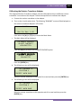
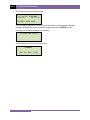
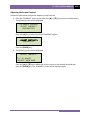
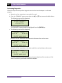
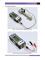
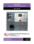
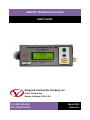
RESISTOR TRANSDUCER ADAPTER
USER’S GUIDE
Vanguard Instruments Company, Inc.
1520 S. Hellman Ave.
Ontario, California 91761, USA
TEL: (909) 923-9390
FAX: (909) 923-9391
March 2011
Revision 1
CT-7500 S2 USER’S MANUAL
REV 2
Calibrating the Resistor Transducer Adapter
The Vanguard Resistor Transducer Adapter must be calibrated each time a different resistor
transducer is connected to the adapter. Follow the steps below to calibrate the adapter:
a. Connect the resistor transducer to the adapter.
b. Turn on the circuit breaker timer. The following “RUNNING” screen will be displayed on
the resistor transducer adapter’s LCD screen:
RUNNING
Res Enc Rev: 1.00
Press either the [▲] or [▼] key to access the Main Menu.
c. The Main Menu will be displayed:
CALIBRATE ENCODER
ADJUST CONTRAST
<DIAGNOSTIC>
Press the [▲] key to select the CALIBRATE ENCODER option:
<CALIBRATE ENCODER>
ADJUST CONTRAST
DIAGNOSTIC
Press the [ENTER] key.
d. The following screen will be displayed:
SET ENCODER TO
POSITION 1
“ENTER” WHEN DONE
Move the resistor transducer to one end of its travel and then press the [ENTER] key.
e. The following screen will be displayed:
SET ENCODER TO
POSITION 2
“ENTER” WHEN DONE
Move the resistor transducer to the opposite end of its travel and then press the
[ENTER] key.
1
REV 2
CT-7500 S2 USER’S MANUAL
f. The following screen will be displayed:
↑/↓ TO SET DISTANCE
5.00 IN
12.70 CM
“ENTER” WHEN DONE
Press the [▲] or [▼] key to set the value to the known traveled distance (distance
between the endpoints of the transducer) and then press the [ENTER] key. The
following screen will be displayed momentarily:
CALIBRATION SAVED
The following screen will then be displayed:
RUNNING
Res Enc Rev: 1.00
2
CT-7500 S2 USER’S MANUAL
REV 2
Adjusting the Screen Contrast
Follow the steps below to adjust the adapter’s screen contrast
a. From the “RUNNING” screen, press either the [▲] or [▼] key to access the Main Menu.
The following screen will be displayed:
CALIBRATE ENCODER
ADJUST CONTRAST
<DIAGNOSTIC>
Press the [▲] key to select the ADJUST CONTRAST option:
CALIBRATE ENCODER
<ADJUST CONTRAST>
DIAGNOSTIC
Press the [ENTER] key.
b. The following screen will be displayed:
ADJUST CONTRAST
↑/↓ TO ADJUST
“ENTER” WHEN DONE
Press the [▲] or [▼] key to adjust the screen contrast to the desired level and then
press the [ENTER] key. The “RUNNING” screen will be displayed again.
3
REV 2
CT-7500 S2 USER’S MANUAL
Performing Diagnostics
Follow the steps below to perform diagnostics and confirm that the adapter is calibrated
properly:
a. Move the resistor transducer to one end of its travel.
b. From the “RUNNING” screen, press either the [▲] or [▼] key to access the Main Menu.
The following screen will be displayed:
CALIBRATE ENCODER
ADJUST CONTRAST
<DIAGNOSTIC>
The DIAGNOSTIC option should be highlighted. Press the [ENTER] key.
c. The following screen will be displayed:
ENCODER TRAVEL:
0.00 IN
0.00 CM
“ENTER” WHEN DONE
Move the resistor transducer and observe the distance values on the screen:
ENCODER TRAVEL:
2.23 IN
5.66 CM
“ENTER” WHEN DONE
Move the resistor transducer to the other end of its travel and observe the screen:
ENCODER TRAVEL:
5.00 IN
12.7 CM
“ENTER” WHEN DONE
The value should be the distance between the two endpoints of the transducer. If this
value is not correct, you should calibrate the adapter.
4
CT-7500 S2 USER’S MANUAL
REV 2
Connection Illustrations
Figure 1. Typical Connection to ABB AHMB Transducer
Figure 2. Typical Connection to a Resistor Transducer
5
1520 S. Hellman Ave • Ontario, CA 91761 • USA
Phone: 909-923-9390 • Fax: 909-923-9391
www.vanguard-instruments.com
Copyright © 2011 by Vanguard Instruments Company, Inc.
Resistor Transducer Adapter Calibration Procedure • Revision 1.0 • March 1, 2011 • TA