1
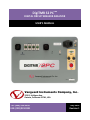
DigiTMR S2 PCTM
DIGITAL CIRCUIT BREAKER ANALYZER
USER’S MANUAL
Vanguard Instruments Company, Inc.
1520 S. Hellman Ave.
Ontario, California 91761, USA
TEL: (909) 923-9390
FAX: (909) 923-9391
July 2012
Revision 1
DIGITMR S2 PC USER’S MANUAL
REV 1
SAFETY SUMMARY
FOLLOW EXACT OPERATING PROCEDURES
Any deviation from the procedures described in this User’s Manual may create one or more
safety hazards, may damage the DigiTMR S2 PC, or cause errors in the test results. Vanguard
Instruments Company, Inc. assumes no liability for unsafe or improper use of the DigiTMR S2
PC.
All safety precautions provided in this manual must be observed during all phases of testing
including test preparation, test lead connection, actual testing, and test lead disconnection.
SAFETY WARNING AND CAUTIONS
The DigiTMR S2 PC shall be used only by trained operators. When using the DigiTMR S2 PC in
Time-versus-Travel mode, all circuit breakers under test shall be off-line and fully isolated.
DO NOT MODIFY TEST EQUIPMENT
To avoid the risk of introducing additional or unknown hazards, do not install substitute parts or
perform any unauthorized modification to any DigiTMR S2 PC test unit. To ensure that all
designed safety features are maintained, it is highly recommended that repairs be performed
only by Vanguard Instruments Company factory personnel or by an authorized repair service
provider. Unauthorized modifications can cause safety hazards and will void the manufacturer’s
warranty.
WARNING
Do not remove test leads during a test. Failure to heed this warning can result in damage to the
equipment.
i
REV 1
DIGITMR S2 PC USER’S MANUAL
TABLE OF CONTENTS
1.0 INTRODUCTION .................................................................................................................... 1
1.1 General Description and Features ................................................................................... 1
1.2 Operational Modes .......................................................................................................... 3
1.2.1. “On-Line” Mode ....................................................................................................... 3
1.2.2. Time-versus-Travel Circuit Breaker Analyzer Mode ................................................. 3
1.3 Technical Specifications ................................................................................................... 4
1.4 DigiTMR S2 PC Controls and Indicators ........................................................................... 5
2.0 OPERATING PROCEDURES ................................................................................................... 6
2.1 Configuring the VCBA S2 Software for use with the DigiTMR S2 PC ............................... 6
2.2 Connecting the DigiTMR S2 PC to a PC via Bluetooth ..................................................... 8
2.3 DigiTMR S2 PC Cable Connections ................................................................................. 16
2.3.1. Contact Cable Connections .................................................................................... 16
2.3.2. Initiate Cable Connections ..................................................................................... 17
2.3.3. Analog and Digital Voltage Monitor Connections .................................................. 19
2.3.5. AC Current Sensor Connection ............................................................................... 22
2.3.6. Transducer Connections ......................................................................................... 23
3.0 GLOSSARY OF TERMS ......................................................................................................... 26
4.0 Compatible Transducers and Transducer Adapters .......................................................... 27
LIST OF TABLES
Table 1. DigiTMR S2 PC Technical Specifications ............................................................................ 4
LIST OF FIGURES
Figure 1. DigiTMR S2 PC Controls and Indicators ........................................................................... 5
Figure 2. Contact Cable Connections ............................................................................................ 16
Figure 3. DC Trip and DC Close Initiate Circuit Cable Connections ............................................... 17
Figure 4. DC Trip and AC Close Initiate Circuit Cable Connections ............................................... 18
Figure 5. Analog and Digital Voltage Monitoring Cable Connections .......................................... 19
Figure 6. External Trigger Cable Connection for an Open Connection......................................... 20
Figure 7. External Trigger on a Close Operation Less 52Y Delay Time ......................................... 21
Figure 8. Typical CT Connection .................................................................................................... 22
Figure 9. Typical Transducer Connection ...................................................................................... 23
Figure 10. Typical Resistor Type Transducer Connection ............................................................. 24
Figure 11. Vanguard Resistor Transducer Adapter Connected to an ABB AHMB Transducer ..... 24
Figure 12. Vanguard Doble Transducer Adapter Connected to a Doble Linear Transducer ........ 25
Figure 13. Vanguard Doble Transducer Adapter Connected to a Doble Rotary Transducer ....... 25
ii
DIGITMR S2 PC USER’S MANUAL
1.0
INTRODUCTION
1.1
General Description and Features
REV 1
The Vanguard DIGITMR S2 PC is an inexpensive, easy to use digital circuit breaker analyzer that
is designed to be used with a PC. This inexpensive analyzer offers the most cost-effective
method for testing circuit breakers. It can fully analyze a circuit-breaker’s performance by
testing the contact time, stroke, velocity, over-travel, and contact wipe. Contact-motion
analysis can be performed for all breaker contact operations (Open, Close, Open – Close, Close
– Open, and Open – Close – Open). The DIGITMR S2 PC offers three dry-contact channels (for
timing circuit breaker main and insertion resistor contacts), one digital transducer channel (to
monitor CB contact motion), and two voltage monitoring channels.
“On-Line” Timing Mode Option
An optional “on-line” timing mode is available for the DIGITMR S2 PC. In this mode, the
DIGITMR S2 PC captures the breaker’s trip or close time, the trip/close coil current
“fingerprint,” and the battery supply voltage while the breaker is still in service. The trip/close
time is derived from the time of trip, or close coil initiation, to the breaker’s bushing current
breaker-make as detected by an AC clamp-on current sensing probe.
The “on-line” timing mode can detect a breaker’s operating conditions with little or no down
time. In this mode, the first trip operation time of the breaker is captured. If a breaker has been
in service for a long period of time and sitting in close position, the first trip time of the breaker
may be slow possibly due to a sticky mechanism. The “on-line” mode is very useful in such
cases because traditional breaker timing may not detect this condition since several operations
may have occurred before the first timing test is conducted.
Open/Close Coil Current Monitoring
A built-in Hall-Effect current sensor records the circuit breaker’s operating coil current
amplitude and duration. The circuit breaker’s operating-coil waveforms (effectively, a
performance “fingerprint” or “current profile”) can be used as a diagnostic tool for analyzing a
circuit breaker’s performance.
Contact Timing Inputs
Dry-contact input channels are used for timing circuit-breaker contacts. Each contact input
channel can detect main contact and insertion resistor contact times in milliseconds and cycles.
Three contact timing channels are available on the DIGITMR S2 PC.
Breaker Stroke and Velocity
One digital transducer input channel is available to measure circuit breaker contact stroke,
velocity, over-travel, and bounce-back. With the use of a Vanguard digital travel transducer, no
set-up calibration is required before testing. A special feature is also available to “Slow-Close”
test a circuit breaker and obtain test results. An optional Resistor Transducer Adapter Device
can be used to interface with any resistor transducer.
1
REV 1
DIGITMR S2 PC USER’S MANUAL
CT Input
One non-contact AC current sensor is used to monitor circuit breaker on-line current for the
“on-line” timing mode.
Voltage Monitoring Input
One analog input channel, designated as (V1), is dedicated to monitoring the substation DC
supply or coil voltage (0-255 Volts, DC or peak AC). A second voltage input channel, designated
as V2, is dedicated to detecting voltage On/Off status (presence or absence). This input can be
used to monitor the status of an A/B switch.
Circuit Breaker Initiate Feature
A built-in solid-state initiate device is used to operate the circuit breaker from the DIGITMR S2
PC. Operational modes include Open, Close, Open-Close, Close-Open, and Open-Close-Open.
Multiple operations such as Open-Close, Close-Open, and Open-Close-Open can be initiated
using a programmable delay or by sensing the circuit breaker’s contact condition.
Computer Interface
One USB interface port and an optional Bluetooth interface is available for computer-control.
Vanguard's Windows®-based Circuit Breaker Analyzer Series 2 (VCBA S2) software is included
with each DIGITMR S2 PC. The software can be used to control the unit, review test records,
and create circuit breaker test plans. Test records can be exported to PDF, Excel, and XML
format. All future software updates can be downloaded from the Vanguard web site at no
additional charge.
2
DIGITMR S2 PC USER’S MANUAL
1.2
REV 1
Operational Modes
1.2.1. “On-Line” Mode
In “On-Line” mode, the trip/close time is derived from the time of trip, or close-coil initiation, to
the breaker’s bushing current-break-or-make as detected by an AC clamp-on current sensing
probe. The DigiTMR S2 PC can time a circuit breaker’s OPEN operation by sensing the time when
the OPEN coil is energized until the bushing CT current returns to zero. The breaker’s CLOSE time
is detected when the close coil is energized until the bushing CT current is detected. The “On-Line”
mode provides a quick way to diagnose a breaker’s performance and can reduce maintenance
costs.
1.2.2. Time-versus-Travel Circuit Breaker Analyzer Mode
In Time-versus-Travel mode, the DigiTMR S2 PC applies a test voltage of 35 Vdc to each of the
contact channels, thus allowing an analog to digital converter (A/D) to determine a close, open,
or an insertion resistor as the state of the contact. The DigiTMR S2 PC records into memory
20,000 readings (in on second) from the A/D’s and the transducer position counters. The
contact time, circuit breaker stroke and velocity are then derived from the stored data.
NOTE
The DigiTMR S2 PC’s travel transducer employs optical encoders to send quadrature
signals to the unit’s counters. With the use of digital transducers and counters, the
need to setup or calibrate the transducers is eliminated.
3
REV 1
1.3
DIGITMR S2 PC USER’S MANUAL
Technical Specifications
Table 1. DigiTMR S2 PC Technical Specifications
TYPE
PHYSICAL SPECIFICATIONS
INPUT POWER
DRY-CONTACT INPUTS
TIMING WINDOWS
TIMING RESOLUTIONS
TIMING ACCURACY
DRY-CONTACT DETECTION
RANGE
RESISTOR DETECTION RANGE
TRIGGER INPUT VOLTAGE
Portable digital circuit breaker analyzer
18.5"W x 14"H x 7"D (47.0 cm x 35.7cm x 17.6 cm); Weight: 16 lbs (7.3 kg)
3 Amps, 100 – 240 Vac, 50/60 Hz
3 dry-contact channels; each channel detects main contact and insertion resistor
contact
1 second, 10 seconds, or 20 seconds
±50 micro-seconds @ 1 sec. duration,
±500 micro-seconds @ 10 sec. duration,
±1.0 milliseconds @ 20 sec. duration
0.05% of reading ±0.1 milliseconds @ 1 second duration
Closed: less than 20 ohms; Open: greater than 5,000 Ohms
50 – 5,000 ohms
Open/Close: 30 – 300 V, DC or peak AC
VOLTAGE SENSING INPUT RANGE
V1: analog input; 0 – 255V, DC or peak AC; Sensitivity: ±1V
V2: voltage presence/absence detector input; 30 – 300V, DC or peak AC
BREAKER OPERATIONS
Initiate Open, Close, Open – Close, Close – Open, Open – Close – Open
BREAKER INITIATE CAPACITY
INITIATE CURRENT READING
RANGE
DIGITAL TRAVEL TRANSDUCER
INPUT
CONTACT TRAVEL POINT
DIFFERENCE
CT CURRENT SENSOR
COMPUTER INTERFACES
PC SOFTWARE
SAFETY
ENVIRONMENT
30A, 250 Vac/dc max
One, non-contact, Hall-effect sensor, 0 – 20 amp range, dc to 5Khz
1 digital travel transducer channel; linear range: 0.0 – 60.0 in (±0.005 in)
rotary range: 0 – 360 degrees (±0.006 degrees)
Measures “slow-close” contact-point distances; results can be printed
One, non-contact, 0-100A
One USB port, optional Bluetooth interface
Windows®-based Circuit Breaker Analysis software (VCBA S2) included with
purchase price. Software updates available at
no additional charge
Designed to meet UL/IEC 61010 and CAN/CSA C22.2 No. 1010.1-92 standards
Operating: -10°C to 50° C (15°F to +122° F); Storage: -30° C to 70° C (-22°F to
+158° F)
HUMIDITY
90% RH @ 40°C (104°F) non-condensing
ALTITUDE
2,000 m (6,562 ft) to full safety specifications
CABLES
OPTIONS
WARRANTY
Furnished with full set of test leads (including 20-foot contact leads and 30-foot
contact lead extensions)
transportation case (available for the DIGITMR S2 and travel transducers)
One year on parts and labor
The above specifications are valid at nominal operating voltage and at a
temperature of 25°C (77°F). Specifications may change without prior notice.
NOTE
4
DIGITMR S2 PC USER’S MANUAL
1.4
REV 1
DigiTMR S2 PC Controls and Indicators
The DigiTMR S2 PC’s controls and indicators are shown in Figure 1 below. The purpose of the
controls and indicators may seem obvious, but users should become familiar with them before
using the DigiTMR S2 PC. Accidental misuse of the controls will usually cause no serious harm.
Users should also be familiar with the safety summary found on the front page of this User’s
Manual.
Figure 1. DigiTMR S2 PC Controls and Indicators
5
REV 1
DIGITMR S2 PC USER’S MANUAL
2.0
OPERATING PROCEDURES
2.1
Configuring the VCBA S2 Software for use with the DigiTMR S2 PC
The DigiTMR S2 PC is operated using the Vanguard Circuit Breaker Analyzer Series 2 (VCBA S2)
PC software. Follow the steps below to properly connect the DigiTMR S2 PC and configure the
VCBA S2 application to recognize the unit.
a. Install the VCBA S2 software (please see the VCBA S2 software user’s manual for details)
b. Connect the DigiTMR S2 PC to the PC by connecting a USB cable from an open USB port
on the PC to the unit’s “USB PC” port.
c. Turn on the power on the DigiTMR S2 PC.
d. If this is the first time you are connecting the unit to the PC, Windows will recognize it as
a new device and automatically install necessary drivers. If using Windows XP, you may
be prompted to install drivers. Select the automatic installation option and Windows will
locate the generic drivers necessary.
e. Please note that although the unit is connected via USB, it uses an internal serial
interface to communicate with the PC. As such, it will appear in the windows Device
Manager as a USB Serial Port. Open the Device Manager from the Windows Control
Panel and note the COM port number. For example, in the installation shown below, the
DigiTMR S2 PC is shown as COM10 (USB Serial Port).
6
DIGITMR S2 PC USER’S MANUAL
REV 1
f. Launch the VCBA S2 application. From the “Sys-Config” menu, select “System Setup…”.
The following window will be displayed:
Make sure that the “Enable USB” option is UN-checked. Then, from the “Port” dropdown menu, select the COM port that corresponds to the port that the DigiTMR S2 PC is
connected to. Then click the OK button. The VCBA S2 software will now recognize the
DigiTMR S2 PC.
7
REV 1
2.2
DIGITMR S2 PC USER’S MANUAL
Connecting the DigiTMR S2 PC to a PC via Bluetooth
The DigiTMR S2 PC can also be connected wirelessly to a PC using Bluetooth (if the Bluetooth
option is installed). To connect the unit via Bluetooth, it must first be paired with the PC. Follow
the steps below to pair the DigiTMR S2 PC to a PC via Bluetooth:
For Windows XP:
a. Make sure the DigiTMR S2 PC is turned on. Then double click on the Bluetooth system
tray icon (on the bottom right corner of your computer screen):
b. The “My Bluetooth Places” window will be displayed:
Click on “Add a Bluetooth Device” on the left window pane.
c. The Bluetooth Setup Wizard window will be displayed. Click on the “Next” button. The
PC will scan for nearby devices and list all available Bluetooth devices:
8
DIGITMR S2 PC USER’S MANUAL
REV 1
The DigiTMR S2 PC will be listed as “DigiTmr S/N” where S/N is the device’s serial
number. Click on the icon for the DigiTMR S2 PC and then click on the “Next” button.
d. The following window will be displayed asking for a secret key to connect to the
DigiTMR S2 PC:
Type the word “default” (without the quotes and in all lower-case) and then click on the
“Next” button.
e. The following window will be displayed with the option to connect to the DigiTMR S2 PC
as a serial port:
Make sure to check the box next to “AT Serial” and then click on the “Next” button.
9
REV 1
DIGITMR S2 PC USER’S MANUAL
f. The following confirmation screen will be displayed:
Click on the “Finish” button.
g. The DigiTMR S2 PC will now be displayed in the “My Bluetooth Places” window:
Note the port number listed under the device name. In the above case, the port number
is COM14. Follow the directions in section Error! Reference source not found. to
configure the VCBA S2 software to connect to the DigiTMR S2 PC using this COM port.
10
DIGITMR S2 PC USER’S MANUAL
REV 1
For Windows 7:
a. Make sure the DigiTMR S2 PC is turned on. Then double click on the Bluetooth system
tray icon (on the bottom right corner of your computer screen):
b. The “Bluetooth Devices” window will be displayed:
Click on “Add a device”.
11
REV 1
DIGITMR S2 PC USER’S MANUAL
c. All nearby Bluetooth devices will be listed:
The DigiTMR S2 PC will be listed as “DigiTmr S/N” where S/N is the device’s serial
number. Click on the icon for the DigiTMR S2 PC and then click on the “Next” button.
d. The device pairing screen will be displayed:
Click on “Enter the device’s pairing code” option.
12
DIGITMR S2 PC USER’S MANUAL
REV 1
e. The following window will be displayed:
Type the word “default” (without the quotes and in all lower-case) in the text box and
click on the “Next” button.
f. The following screen will be displayed:
Click on the “Close” button.
13
REV 1
DIGITMR S2 PC USER’S MANUAL
g. The DigiTMR S2 PC will now be listed under “Bluetooth Devices”:
Right click on the DigiTmr S2 PC icon and select “Properties” from the pop-up menu.
h. The properties window will be displayed. Click on the “Hardware” tab:
14
DIGITMR S2 PC USER’S MANUAL
REV 1
Note the port number listed after the device name (COM23 in the above example).
Follow the directions in section Error! Reference source not found. to configure the
VCBA S2 software to connect to the DigiTMR S2 PC using this COM port.
15
REV 1
2.3
DIGITMR S2 PC USER’S MANUAL
DigiTMR S2 PC Cable Connections
2.3.1. Contact Cable Connections
A typical contact cable connection to a circuit breaker is shown in Figure 2. Red clips are
connected to phase A, B, and C of the breaker’s bushings. The black clips are connected to the
ground or common side of the bushings. If the common side of the bushing is not grounded,
jumpers should be installed between the bushings.
NOTE
It is advisable to ground one side of the contacts for most testing purposes. If a
breaker is floating or ungrounded, ensure that the contact input channels are
protected against static discharge.
Figure 2. Contact Cable Connections
16
DIGITMR S2 PC USER’S MANUAL
REV 1
2.3.2. Initiate Cable Connections
The DigiTMR S2 PC will trip or close breakers through a solid-state device which will operate on
any AC or DC control voltage ranging from 10 to 300 Volts. Both the trip and close circuits are
protected by 5-Ampere fuses. A typical DC trip and DC close control circuit test connection is
shown in Figure 3. A typical DC trip and AC close control circuit is shown in Figure 4.
NOTE
Always connect the initiate circuit with an auxiliary switch in series. The auxiliary
switch provides the coil current interruption. Failure to follow this recommendation
will damage the DigiTMR S2 PC initiate circuit.
Figure 3. DC Trip and DC Close Initiate Circuit Cable Connections
17
REV 1
DIGITMR S2 PC USER’S MANUAL
Figure 4. DC Trip and AC Close Initiate Circuit Cable Connections
18
DIGITMR S2 PC USER’S MANUAL
REV 1
2.3.3. Analog and Digital Voltage Monitor Connections
The analog voltage input “V1” is dedicated to monitoring a breaker’s DC control voltage during
an operation. The analog input records the nominal DC voltage at no load and the minimum DC
voltage while the Trip or Close coil is energized.
Nominal and minimum voltage readings can be printed on a tabulated report. Analog
waveforms can also be plotted graphically. Using the reports, the user can see the breaker’s DC
control voltage “dip” under load conditions and can easily detect problems such as a poor
connection or an excessive voltage drop.
The digital voltage input “V2” monitors the voltage status as “ON” or “OFF” states and can
graph the results.
A typical analog voltage monitoring connection (V1) and a typical digital monitoring connection
(V2) are shown in Figure 5.
Maximum voltage recorded is 255 Vdc.
NOTE
Figure 5. Analog and Digital Voltage Monitoring Cable Connections
19
REV 1
DIGITMR S2 PC USER’S MANUAL
2.3.4. External Trigger Input Connections
The External Trigger Mode can be used to start recording when the DigiTMR S2 PC senses a
voltage (see Figure 6). This feature can be used to time a circuit breaker without using the
initiate circuit (for example, if the initiate circuit is non-operational). Another typical application
for the External Trigger Mode is to time a circuit breaker in a close operation and to start timing
only when the close coil is energized, thus bypassing the 52Y relay delay time. The DigiTMR S2
PC will energize the 52Y relay to start the close operation and will then start timing when it
senses the voltage across the closing coil. Please see Figure 7 for a typical test connection.
Another application for the External Trigger Mode is to start timing the breaker when the user
trips or closes the breaker remotely.
NOTES
• Minimum trigger voltage is set at 30 Vac/dc. Maximum continuous voltage is set
at 300 Vac/dc.
• Different trigger voltages can be set at the factory based on specific user
requests.
• The DigiTMR S2 PC will start looking for the external trigger voltage when the
message “AWAITING TRIGGER…” is shown on the LCD. If the external trigger
voltage is not sensed by the DigiTMR S2 PC within ten seconds after the initiate
sequence has begun, the DigiTMR S2 PC will return to the main menu.
Figure 6. External Trigger Cable Connection for an Open Connection
20
DIGITMR S2 PC USER’S MANUAL
REV 1
Figure 7. External Trigger on a Close Operation Less 52Y Delay Time
21
REV 1
DIGITMR S2 PC USER’S MANUAL
2.3.5. AC Current Sensor Connection
The DigiTMR S2 PC can sense a breaker’s bushing current by using a clamp-on AC current sensor
connected to the breaker’s bushing CT. The AC current sensor is used in “On-Line” Mode only.
The AC current sensor requires a minimum of 100 mA to operate. The maximum current is 25
Amperes. A typical AC sensor connection is shown in Figure 8.
Figure 8. Typical CT Connection
22
DIGITMR S2 PC USER’S MANUAL
REV 1
2.3.6. Transducer Connections
A typical transducer connection is shown in Figure 9.
Figure 9. Typical Transducer Connection
23
REV 1
DIGITMR S2 PC USER’S MANUAL
The DigiTMR S2 PC can also be connected to a resistor type transducer such as the ABB AHMB
(see Figure 10 and Figure 11) using the Vanguard Resistor Transducer Adapter (sold separately).
Figure 10. Typical Resistor Type Transducer Connection
Figure 11. Vanguard Resistor Transducer Adapter Connected to an ABB AHMB Transducer
24
DIGITMR S2 PC USER’S MANUAL
REV 1
The DigiTMR S2 PC can also be connected to Doble linear and rotary transducers using the optional
Vanguard Doble Transducer adapter shown below.
Figure 12. Vanguard Doble Transducer Adapter Connected to a Doble TR3189 Linear Transducer
Figure 13. Vanguard Doble Transducer Adapter Connected to a Doble TR31170 Rotary Transducer
25
REV 1
3.0
DIGITMR S2 PC USER’S MANUAL
GLOSSARY OF TERMS
Breaker Bounce-Back Distance
Bounce-back is the distance the breaker contact moves before the resting position after the
over-travel. Bounce-back is typically found in the close operation.
Breaker Over-Travel Distance
Over-travel is the distance the contact moves beyond the resting position. Over-travel is
typically found in the close operation.
Breaker Stroke
Circuit breaker contact stroke is the absolute distance measured from the open position to the
close position, excluding the over-travel and bounce-back distance. The DigiTMR S2 PC uses a
digital transducer to measure a breaker's contact stroke, over-travel and bounce-back. The
digital transducer outputs 200 counts per linear inch of travel, therefore the resolution is
accurate to about 1/200 inch. The output resolution is ±0.01 inch on the test result report.
Unlike resistor-type transducers, the DigiTMR S2 PC’s transducer needs no calibration or setup.
A user verifies the transducer’s functionality by selecting a diagnostic test for the transducer.
Breaker Velocity (Speed)
The DigiTMR S2 PC, when used with a travel transducer, calculates the breaker contact velocity
through the arc zone. Users need to program the calculation points or analysis points on the
travel curve for the unit to calculate the contact velocity. Velocity calculation points are shown
as Point 1 and Point 2 under the “Speed Analysis” section of the tabulated report.
Contact Wipe
Contact wipe is the distance measured from the close position to the contacts touching or
parting positions. In the close operation, contact wipe is measured from the contacts touching
position to the final close position. In the open operation, the contact wipe is measured from
the close position to the contact break or parting position.
NOTE
26
Contact wipe is measured during an operation. The measurement may not be as
accurate as the measurement done using the Slow-Close Mode. It is recommended
that the Slow-Close Test be used to verify the contact wipe measurement.
DIGITMR S2 PC USER’S MANUAL
4.0
REV 1
Compatible Transducers and Transducer Adapters
ABB AHMA-8
Mechanism
Transducer
ABB AHMB-8
Mechanism
Transducer
Linear
Transducers
Available in
10”, 25”, and
30”
Rotary
Transducer
15” Universal
Transducer
Rotary
Transducer
with Magnetic
Mount
Resistor-Type
Transducer
Westinghouse
SF/SFA
Transducer
Resistor
Transducer
Adapter
Doble
Transducer
Adapter
27
1520 S. Hellman Ave • Ontario, CA 91761 • USA
Phone: 909-923-9390 • Fax: 909-923-9391
www.vanguard-instruments.com
Copyright © 2012 by Vanguard Instruments Company, Inc.
DigiTMR S2 PC User’s Manual • Revision 1.0 • July, 2012 • TA