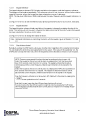
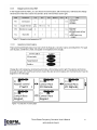
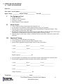
1
$75 Price Each Three Phase Frequency Converter User’s Manual #018-0168-01 Revision B Phone: 1.877.DSPM.POWER 1.877.377.6769 Fax: 909.930.3335 Website: www.DSPManufacturing.com E-Mail: [email protected] Three Phase Frequency Converter User’s Manual #018-0168-01 Rev B 1 Three Phase Frequency Converter User’s Manual #018-0168-01 Rev B 2 Three Phase Frequency Converter User’s Manual #018-0168-01 Rev B 3 Three Phase Frequency Converter User’s Manual #018-0168-01 Rev B 4 REVISION HISTORY REV DATE PRIMARY REASON FOR CHANGE B February. 26, 2013 Production Release LIST OF EFFECTIVE PAGES PAGE REV PAGE REV PAGE REV PAGE REV Three Phase Frequency Converter User’s Manual #018-0168-01 Rev B PAGE REV 5 Reproduction or Distribution forbidden NOTICE: THIS DOCUMENT CONTAINS PROPRIETARY INFORMATION This document contains proprietary and confidential information of Digital Signal Power Manufacturer, Inc. (”Digital Signal Power Manufacturer”). In consideration of the receipt of this document, the recipient agrees not to copy any of its contents, nor to disclose them to or allow them to be used by any person not currently an Digital Signal Power Manufacturer employee or an employee of the recipient having a need to know, without the express written consent of Digital Signal Power Manufacturer, and further agrees to surrender this document to Digital Signal Power Manufacturer when the reason for its receipt has terminated. © 2012 Digital Signal Power Manufacturer, Inc. - All rights reserved Three Phase Frequency Converter User’s Manual #018-0168-01 Rev B 6 About this Manual Thank you for selecting this Three Phase Frequency Converter. It provides you with perfect protection for connected loads and equipment. This manual contains important instructions that should be followed during the installation and maintenance of this DSPM converter. It includes important safety and maintenance instructions for operating the Three Phase Frequency Converter. If you should have any problems with this Three Phase Frequency Converter, please refer to this manual and/or call technical support. Your DSPM Converter is designed to provide reliable protection from power disturbances for many years. Please be sure to follow the manufacturers instructions to ensure optimum performance of the equipment. This manual contains descriptions of all controls and indicators required to operate the DSPM Converter. Please read this manual carefully and retain it for future reference. To the best of our knowledge and at the time written, the information contained in this document is technically correct and the procedures accurate and adequate to operate this instrument in compliance with its original advertised specifications. While every precaution has been made to ensure accuracy and completeness in this manual, DSPM assumes no responsibility and disclaims all liability for damages resulting from the use of this information or for any errors or omissions. This instrument is designed to prevent accidental shock to the operator when properly used. However, no engineering design can render safe an instrument which is used carelessly. Therefore, this manual must be read carefully and completely before making any measurements. Failure to follow directions can result in a serious or fatal accident. How to use this Manual This manual is designed for ease of use, giving the user easy and quick reference to information. This manual uses notice icons to draw attention to the user important information regarding the safe operation and installation of the Frequency Converter. The notice icons used in this manual are explained below, and should be taken into account and adhered to whenever they appear in the text of this manual. Technical Assistance Safety Recommendations: If any problems are encountered while following this manual, DSPM assistance and correspondence is recommended. For technical support or help with any questions not covered in the manual, contract. DSPM Inc. 1921 S. Quaker Ridge Place Ontario, CA 91761 Work Hours: 8 a.m. – 5 p.m. Pacific Standard Time Phone:1(877) DSPM POWER 1(877) 377-6769 After Hours: 5 p.m. – 1 a.m. Pacific Standard Time 1(951) 840-0811 Fax: 1(909) 930-3335 Email: [email protected] Internet: http://www.DSPManufacturing.com To expedite assistance if required, Please have the following information from your unit’s System Label (found on the right side and inside door panel) available: Model: Model Number: S/O Number: Input Voltage: Output Voltage: Power Rating and Frequency: Three Phase Frequency Converter User’s Manual #018-0168-01 Rev B 7 IMPORTANT SAFETY INSTRUCTIONS SAVE THESE INSTRUCTIONS SECTION - SAFETY Notes and Safety Information Following safety precautions is important when operating or servicing electrical equipment. Always heed these precautions since they are essential to the safe operation and servicing of this product. This Manual contains warning symbols which alert the user to check for hazardous conditions. The symbols are used extensively throughout this manual and are defined below. To ensure the safety of operating performance of this electrical equipment, these instructions must be adhered too. WARNING: A Warning notice icon conveys information to protect the user and service personnel against hazardous conditions. DANGER: A Danger notice icon conveys that there is a risk of electric shock, personal injury, or death to the user if instructions are not followed. CAUTION: A Caution notice icon conveys to the user or service personnel information making them aware that there is a possibility of equipment damage. NOTE: A Note notice icon indicates when the user should make a reference of information regarding the Frequency Converter operation, load status and display status. Such information is essential if DSPM, Inc. field service assistance and correspondence is required. CAUTION! ENSURE THAT NO FLUIDS OR OTHER FOREIGN OBJECTS CAN ENTER THE CONVERTER SYSTEM. NOTE! READ THIS MANUAL IN ITS ENTIRETY BEFORE PERFORMING THE INSTALLATION, START-UP, OPERATION, OR MAINTENANCE OF THE FREQUENCY CONVERTER SYSTEMS. FAILURE TO DO SO COULD RESULT IN ELECTROCUTION, FIRE, EXPLOSION, OR EQUIPMENT FAILURE. WARNING! ONLY FACTORY TRAINED OR AUTHORIZED PERSONNEL SHOULD ATTEMPT TO INSTALL OR REPAIR THE FREQUENCY CONVERTER SYSTEM. IMPROPER INSTALLATION HAS PROVEN TO BE THE SINGLE MOST SIGNIFICANT CAUSE OF START-UP PROBLEMS. HIGH AC AND DC ELECTRICAL VOLTAGES ARE PRESENT THROUGHOUT THE UNIT(S) AND INCORRECT INSTALLATION OR SERVICING COULD RESULT IN ELECTROCUTION, FIRE, EXPLOSION, OR Three Phase Frequency Converter User’s Manual #018-0168-01 Rev B 8 EQUIPMENT FAILURE. CAUTION! ALL POWER CONNECTIONS MUST BE COMPLETED BY A LICENSED ELECTRICIAN WHO IS EXPERIENCED IN WIRING THIS TYPE OF EQUIPMENT. WIRING MUST BE INSTALLED IN ACCORDANCE WITH ALL APPLICABLE NATIONAL AND LOCAL ELECTRICAL CODES. IMPROPER WIRING MAY CAUSE DAMAGE TO THE EQUIPMENTS, INJURY OR DEATH OF PERSONNEL. VERIFY THAT ALL HIGH AND LOW VOLTAGE INPUT POWER CIRCUITS ARE DE-ENERGIZED AND LOCKED OUT BEFORE INSTALLING CABLES OR MAKING ANY ELECTRICAL CONNECTIONS. NOTE! THIS EQUIPMENT GENERATES, USES, AND CAN RADIATE RADIO FREQUENCY ENERGY, AND, IF NOT INSTALLED AND USED IN ACCORDANCE WITH THIS MANUAL, MAY CAUSE INTERFERENCE TO RADIO COMMUNICATIONS. IT HAS BEEN TESTED AND FOUND TO COMPLY WITHIN THE LIMITS FOR A COMPUTING DEVICE PURSUANT TO SUB PART J OF PART 15 OF FCC RULES, WHICH ARE DESIGNED TO PROVIDE REASONABLE PROTECTION AGAINST SUCH INTERFERENCE WHEN OPERATED IN A COMMERCIAL ENVIRONMENT. DANGER! LETHAL VOLTAGES EXIST WITHIN THE EQUIPMENT DURING OPERATION. EXTREME CAUTION IS REQUIRED WHEN PERFORMING MAINTENANCE. OBSERVE ALL WARNINGS AND CAUTIONS IN THIS MANUAL. FAILURE TO COMPLY MAY RESULT IN SERIOUS INJURY OR DEATH. OBTAIN QUALIFIED SERVICE FOR THIS EQUIPMENT AS INSTRUCTED. DANGER! BE CONSTANTLY AWARE THAT THE FREQUENCY CONVERTER SYSTEM CONTAINS HIGH DC AS WELL AS AC VOLTAGES. WITH INPUT POWER OFF AND THE BATTERY, DISCONNECTED, HIGH VOLTAGE AT THE FILTER CAPACITORS AND POWER CIRCUITS SHOULD DISCHARGE WITHIN 30 SECONDS. HOWEVER, POWER CIRCUIT FAILURES CAN OCCUR, SO YOU SHOULD ALWAYS ASSUME THAT HIGH VOLTAGE MIGHT STILL EXIST 30 SECONDS AFTER SHUTDOWN. VERIFY THAT POWER IS OFF USING AC AND DC VOLTMETERS BEFORE MAKING CONTACT. DANGER! SOME COMPONENTS WITHIN THE CABINETS ARE NOT CONNECTED TO CHASSIS GROUND. ANY CONTACT BETWEEN FLOATING CIRCUITS AND THE CHASSIS IS A LETHAL SHOCK HAZARD. Three Phase Frequency Converter User’s Manual #018-0168-01 Rev B 9 DANGER! OBSERVE ALL SAFETY PRECAUTIONS DURING SERVICE OF THE FREQUENCY CONVERTER. EVEN WITH THE MAIN CIRCUIT BREAKERS IN THE OFF POSITION, THE DANGER OF ELECTROCUTION MAY STILL BE PRESENT. THE UTILITY POWER TO THE UNIT MUST BE LOCKED AND TAGGED “OFF” BEFORE PERFORMING ANY SERVICE OR WORK ON THE UNIT. FAILURE TO FOLLOW THOSE INSTRUCTIONS AND THE INSTRUCTION LISTED ABOVE AND ELSEWHERE IN THIS MANUAL COULD RESULT IN AN EXPLOSION, FIRE, EQUIPMENT FAILURE, OR ELECTROCUTION. CAUTION! EXERCISE EXTREME CARE WHEN HANDLING FREQUENCY CONVERTER CABINETS TO AVOID EQUIPMENT DAMAGE OR INJURY TO PERSONNEL. CABINETS WEIGH SEVERAL HUNDRED POUNDS. CAUTION! TEST LIFT AND BALANCE THE CABINETS BEFORE MOVING. MAINTAIN MINIMUM TILT FROM VERTICAL AT ALL TIMES. THE BOTTOM STRUCTURE WILL SUPPORT THE UNIT ONLY IF THE FORKLIFT FORKS ARE COMPLETELY UNDERNEATH THE UNIT. WARNING! LEAD-ACID BATTERIES CONTAIN HAZARDOUS MATERIALS. BATTERIES MUST BE HANDLED, TRANSPORTED, AND RECYCLED OR DISCARDED IN ACCORDANCE WITH FEDERAL, STATE, AND LOCAL REGULATIONS. BECAUSE LEAD IS A TOXIC SUBSTANCE, LEAD-ACID BATTERIES SHOULD BE RECYCLED RATHER THAN DISCARDED. DO NOT DISPOSE OF BATTERIES IN A FIRE, THE BATTERIES MAY EXPLODE. DO NOT OPEN OR MUTILATE THE BATTERIES. RELEASED ELECTROLYTE IS HARMFUL TO THE SKIN AND EYES AND MAY BE TOXIC. A BATTERY CAN HAVE A HIGH SHORT CIRCUIT CURRENT AND PRESENT A RISK OF ELECTRICAL SHOCK. THE FOLLOWING PRECAUTIONS SHOULD BE OBSERVED WHEN WORKING ON BATTERIES: 1. 2. 3. 4. 5. REMOVE WATCHES, RINGS OR OTHER METAL OBJECTS. USE TOOLS WITH INSULATED HANDLES. WEAR RUBBER GLOVES AND BOOTS. DO NOT LAY TOOLS OR METAL PARTS ON TOP OF BATTERIES. DISCONNECT CHARGING SOURCE PRIOR TO CONNECTING OR DISCONNECTING BATTERY TERMINALS. 6. DETERMINE IF BATTERY IS INADVERTENTLY GROUNDED. IF SO, REMOVE THE SOURCE OF THE GROUND. CONTACT WITH ANY PART OF A GROUNDED BATTERY CAN RESULT IN ELECTRICAL SHOCK. THE LIKELIHOOD OF SUCH SHOCK WILL BE REDUCED IF SUCH GROUNDS ARE REMOVED DURING INSTALLATION AND MAINTENANCE. Three Phase Frequency Converter User’s Manual #018-0168-01 Rev B 10 7. LEAD-ACID BATTERIES CAN PRESENT A RISK OF FIRE BECAUSE THEY GENERATE HYDROGEN GAS. THE FOLLOWING PROCEDURES SHOULD BE FOLLOWED: DO NOT SMOKE WHEN NEAR BATTERIES. DO NOT CAUSE FLAME OR SPARK IN BATTERY AREA. 8. DISCHARGE STATIC ELECTRICITY FROM YOUR BODY BEFORE TOUCHING BATTERIES BY FIRST TOUCHING A GROUNDED SURFACE. CAUTION! IN CASE OF FIRE INVOLVING ELECTRICAL EQUIPMENT. ONLY CARBON DIOXIDE FIRE EXTINGUISHERS, OR THOSE APPROVED FOR USE ON ELECTRICAL EQUIPMENT, SHOULD BE USED. USE OF WATER ON FIRES INVOLVING LIVE HIGH VOLTAGE ELECTRICAL CIRCUITS COULD PRESENT AN ELECTROCUTION HAZARD. DANGER! TO REDUCE THE RISK OF ELECTRICAL SHOCK; DISCONNECT THE THREE PHASE FREQUENCY CONVERTER FROM THE MAIN SUPPLY BEFORE INSTALLING AN INTERFACE SIGNAL CABLE. RECONNECT THE POWER ONLY AFTER SIGNALING INTERCONNECTIONS HAVE BEEN MADE. DO NOT DISMANTLE THE THREE PHASE FREQUENCY CONVERTER. Three Phase Frequency Converter User’s Manual #018-0168-01 Rev B 11 1. INTRODUCTION 1.1. GENERAL The principles of operation described herein are applicable to all models. The product is an advanced Three Phase Frequency Converter based on Intelligent Microprocessor Control that meets or exceeds the life safety codes of UL924 and UL1778. Under normal power conditions, this design enables the system to adjust and filter power fluctuations continuously and automatically. The this unit uses a Digital Signal Processing/Pulse-Width Modulation (DSP/PWM) Monitoring System for managing the system. The DSP/PWM Monitoring System is temperature compensated resulting in maintaining maximum operating parameters. It is listed for compliance to UL1778, UL924, UL924A and CSA107.1 standards. The Frequency Converter is available with a variety of three phase input and output voltages and frequencies. This information is provided on the System Labels located on the inside front door and the right side of the Converter. See Chapter 2 for a complete listing of the Frequency Converter specifications. This manual provides an overview of the Frequency Converter components and their functions. The appearance and purpose of operator controls and indicators is described with procedures for operation, start-up, and basic maintenance included. 1.2 THEORY OF OPERATION 1.2.1. Standby Mode After power is applied, the system is placed in STANDBY mode and a self-check starts. During this period, the start subroutine checks for the input voltage and proper operation of the converter. After the routine is completed and check confirmed OK, the system goes into the NORMAL mode. 1.3 OVERVIEW 1.3.1. Drive Principle of Operation Figure 1.3.1 presents the block diagram of the Vacon drive unit. The drive mechanically consists of two units, the Power Unit and the Control Unit. The three-phase AC-choke (1) at the mains end together with the DC-link capacitor (2) form an LC-filter, which, again, together with the diode bridge produce the DC-voltage supply to the IGBT Inverter Bridge (3) block. The AC-choke also functions as a filter against High Frequency disturbances from the mains as well as against those caused by the frequency converter to the mains. It, in addition, enhances the waveform of the input current to the frequency converter. The entire power drawn by the frequency converter from the mains is active power. The IGBT Inverter Bridge produces a symmetrical, 3-phase PWM-modulated AC-voltage to the motor/ Output Filter. The Motor and Application Control Block is based on microprocessor software. The microprocessor controls the motor basing on the information it receives through measurements, parameter settings, control I/O and control keypad. The motor and application control block controls the motor control ASIC which, in turn, calculates the IGBT positions. Gate drivers amplify these signals for driving the IGBT inverter bridge. The control keypad constitutes a link between the user and the frequency converter. The control keypad is used for parameter setting, reading status data and giving control commands. It is detachable and can be operated externally and connected via a cable to the frequency converter. Instead of the control keypad, also a PC can be used to control the frequency converter if connected through a similar cable. Three Phase Frequency Converter User’s Manual #018-0168-01 Rev B 12 Figure 1.3.1 Three Phase Frequency Converter User’s Manual #018-0168-01 Rev B 13 2. SPECIFICATIONS The Frequency Converter maintains efficient AC Power to operate all output loads, providing superior dependability and security to commercial/industrial environments in a small footprint. The System Label displays the rated kW as well as nominal voltages. There are System Labels located on the interior side of the Frequency Converter front door and the exterior right side of the unit. Table 2.1 2.1. POWER RATING Eight to one-hundred and twenty-five KVA three phase output unit uses the latest DSP/PWM technology to provide the most advanced performance and reliability features. 2.2. INPUT Refer to Table 2.1 2.3. OUTPUT Refer to Table 2.1 2.4. CODES 2.4.1. Listed to UL 924, meets NFPA 101, NFPA 70, NEC and OSHA standards 2.4.2. Cities of Chicago and New York approved 2.4.3. Complies with the Buy American Act 2.5. PROTECTION 2.5.1. Provides overload, surge and undercurrent protection using DSP/PWM technology to protect system performance and reliability 2.5.2. Surge protection against load surges as defined in ANSI/IEEE C62.45 category A and B Three Phase Frequency Converter User’s Manual #018-0168-01 Rev B 14 2.6. DIAGNOSTICS AND MAINTENANCE 2.6.1. DSP/PWM technology provides complete self diagnostic capabilities and LCD Monitoring 2.6.2. Informative advanced Display and Alarms keep you in control of your operating environment 24/7 2.6.3 Automatically performs periodic self-tests ensuring a safely operating environment prior to an emergency. 2.6.4. Water Dots are placed on every shelf and door panel to indicate if moisture is present or has got inside the unit. The Dots are originally white in color but will turn red when water are absorbed. 2.7. CABINET 2.7.1. Modular design enables flexible installation 2.7.2. Forced air cooling for maximum reliability 2.7.3. All systems are self contained 2.8. INSTALLATION 2.8.1. Modular design and small footprint allow easy installation in electrical closet or other convenient locations 2.8.2. Phone assisted factory start-up standard for all systems 2.8.3. Extended warranty available 2.9. SPECIAL APPLICATIONS 2.9.1. DSPM offers numerous UL924 optional devices to meet unusual or difficult application parameters 2.9.2. ECM - Environmental Circuit Module allows fixtures and lamps on the emergency circuit (s) to be operated by normal switching and/or dimming devices in non-emergency conditions 2.9.3. Dimming Panel Interface allows use with emergency lights controlled by common dimmer panel 2.10. WARRANTY 2.10.1. One-Year full warranty on system electronics 2.10.2. System 1-year on-site warranty labor with DSPM phone assisted start-up 2.10.3. Five-Year powertrain warranty 2.10.4. Maintenance contracts available 3. FIELD REPLACEABLE UNITS (FRUS) Each FRUS comes with detail instructions of how the part should be performed. At the ends of most wires/ cables are labels that indicates their locations. When ordering replacement parts from the factory, supply the information from the System Label (refer to Technical Assistance section in this manual). Include the model number, serial number, input/output voltages, and power rating when ordering parts. Replacement parts must be replaced by qualified factory trained service personnel only. Circuit boards and IGBTs contain ESDS (Electro-Static Discharge Susceptible) components. Handle and package ESDS devices in accordance with JEDEC standard JESD625-A. Use a grounded ESD wrist strap when handling the devices and circuit boards. Always package components and circuit boards in static-dissipative plastic bags or the static-dissipative material that the FRUS came in before transporting (Even if a device has failed). Failure to do so could result in further damage, complicating repair and failure analysis. 3.1. All Parts Verify that the cables are marked before disconnecting. Replace the defective part with the new part. Reconnect wiring the same way as it was disconnected. Three Phase Frequency Converter User’s Manual #018-0168-01 Rev B 15 4. TRANSPORTATION, INSPECTION, AND INSTALLATION 4.1. HOW TO TRANSPORT THE SYSTEM Note: Do not transport in a horizontal position. Cabinets should be maintained upright within +/- 15° of the vertical during handling. 4.2. INSPECTION 4.2.1. Upon receipt, inspect the container and pallet for shipping damage. If there was any damage during transportation; Do Not turn on the unit. Immediately notify the shipping agent/transportation carrier and DSPM. If no damage is evident, move the packed DSPM Frequency Converter to its installation location. The packaging is recyclable; keep it for reuse or please disposed of it. 4.2.2. Using care to avoid puncturing the shipping material with any sharp objects, which would damage the contents, open the shipping material by carefully removing any banding and shipping material from the sides, ends and top. 4.2.3. Remove the packing and vapor barrier and inspect the equipment for any obvious shipping damage. It is recommended that the units not be loosened from the shipping pallet until after all handling by forklift or pallet jack is completed. 4.2.4. Immediately file a claim with the shipping agency if any damage, as a result of shipping, is observed. 4.2.5. Follow these steps to inspect all surfaces for abrasions and dents: 4.2.5.1. Open the front door of the cabinet. 4.2.5.2. Verify that all the transformers, inductors, electrical, and electronic devices are firmly mounted. 4.2.5.3. Verify that the transformer coils and terminal lugs are free of contact with any grounded metal surface and that the transformer terminal wires are securely connected. 4.2.5.4. Verify that the internal Wiring is not damaged. 4.2.5.5. Verify that all wires to and from the output filter assembly, input filter assembly, inverter assembly, and bypass switch are securely connected. 4.2.5.6. Verify that the circuit breakers are firmly seated and that the wires are securely connected. 4.2.5.7. Inspect all batteries for damage (cracks, leaks, loose connections, etc.,) 4.2.5.8. Reinstall all panels, covers and close all doors. 4.3 LOCATION AND PLACEMENT 4.3.1. Before starting, check the load tolerance of the floor and verify that the floor will be able to support the Frequency Converter at its final destination and the route to get it there. After verifying the weights verify that when the unit is placed in its final position that the minimum clearances required have been met. Install the Three Phase Frequency Converter in a protected area with adequate airflow and free from excessive dust. Do not operate the Three Phase Frequency Converter where the temperature and humidity is out of the specified limits. Water Dots are placed on every shelf and door panel to indicate if moisture is present or has got inside the unit. The Dots are originally white in color but will turn red when water is absorbed. WARNING: Condensation of water may occur if the system is unpacked in a very low temperature environment. In this case it is necessary to wait until the system is fully dry inside before proceeding with the connection of any power; otherwise an electrical shock hazards might exist. Installation and wiring must be performed in accordance with the local electrical code and under the guidance or instructions of professional personnel. Note: Per code requirements, leave 3” on each side of the cabinet (including the back) and 3 foot clearance in front (Refer to Figure 4.3.1). Storage of the system should be in a cool and dry area with the unit being upright and covered. The warranty can be affected if the unit is stored for more then 3 months without charging the batteries. Operating Temperature: 0º to 40ºC (32º to 104ºF); Storage Temperature: -20º to 60ºC (-4º to 140ºF) Three Phase Frequency Converter User’s Manual #018-0168-01 Rev B 16 Figure 4.3.1 5. DESCRIPTION 5.1. DESCRIPTION OF FREQUENCY CONVERTER’S CABINET 5.1.1. SYSTEM COMPONENT LAYOUT The following layouts will help you find the parts and components in your Emergency Lighting Inverter. Maintenance should only be performed by factory-trained or qualified personnel. Do not attempt to service. If you need technical assistance, please contact DSPM. 1 Input Terminal Block—TB1 2 Input Circuit Breaker—CB1 3 Output Circuit Breaker—CB2 4 Output Terminal Block—TB2 5 0-10V Reference Transformer—T3 6 Fan Transformer—T5 7 0-10V Bridge Rectifier 8 Fan Fuses—F3 and F4 9 0-10V Interface PCBA 10 Fan Assembly—Fan-1 and Fan-2 11 Variable Frequency Drive—VFD/IMU 12 Inverter input Filter Capacitors—C1, C2, and C3 13 Inverter Output Filter Capacitors—C3, C4, and C4 14 Inverter Output Filter Capacitors Terminal Block 15 Inverter Transformer—T1 16 Inductors—L1, L2, and L3 17 Remote LCD Control Panel—(Not shown in Figure) Table 5.1.1 Three Phase Frequency Converter User’s Manual #018-0168-01 Rev B 17 6 8 2 1 3 5 4 7 9 11 10 12 15 13 16 14 Figure 5.1.1 The AC Input, AC Output Terminals Blocks are provided for the connection of incoming power and the connection of the load (equipment) intended to be powered by the Frequency Converter. Refer to Figure 5.1.1Component Layout for these connections and their locations in the Frequency Converter Cabinet. Lethal voltages exist within the cabinet, even when the unit is on bypass. Only qualified service personnel with adequate training must service this equipment. 6. INSTALLATION 6.1. INPUT POWER CONNECTIONS It is highly recommended that a qualified electrician make all input power connections. The input power should be connected correctly at the required voltages and the ground cable should be of the same gauge as the input power cables. Ensure that the utility power to be connected is rated as on the system label. Make sure the hots, neutral and grounds are correctly identified and wired to the input terminal block as designated. Phase rotation should be checked and verified for clockwise rotation. The DSPM System will automatically configure the phase rotation in the forward direction (even if the input power is miss-wired). However, the output of the DSPM System will not automatically configure the phase rotation in the forward direction. Therefore, the DSPM System output power should be checked for proper forward phase rotation. The input power connections to the Frequency Converter come from the building supplied services. These connections are made inside the Frequency Converter cabinet (Refer to Figure 5.1.1a-Component System Layout). The input cables are connected to a five (5) pole terminal block(TB1) which is comprised of three (3) input power, neutral, and ground connections. Three Phase Frequency Converter User’s Manual #018-0168-01 Rev B 18 6.2. OUTPUT POWER CONNECTIONS It is highly recommended that a qualified electrician make all output power connections. The output power should be connected correctly at the required voltages and the ground cable should be of the same gauge as the output power cables. Ensure that the loads to be connected are as listed on the system label, and the hots, neutral and grounds are correctly identified and are wired to the output terminal block as designated. Loads not powered by the system cannot use the neutral of the Three Phase Frequency Converter. Do not bond the output neutral to chassis ground! The system has been bonded as required by the manufacturer and National Electrical Code. These connections are made inside the Frequency Converter cabinet (Refer to Figure 5.1.1aComponent System Layout). The output cables are connected to a five (5) pole terminal block (TB1) which is comprised of three (3) input power, neutral, and ground connections. The output over current protection from the DSPM Frequency Converter System is the responsibility of the End User. 6.3. SYSTEM CURRENT RATINGS All circuit breakers provided by the end user that are connected to the inputs and outputs, need to be of the “High Inrush” type. This is to prevent the breakers from tripping during the startup of the unit and its load. DSPM uses only the “High Inrush” type of breaker in its units. Refer to Charts 6.3.1-13 when determining the size of your input and output breakers. Three Phase Frequency Converter User’s Manual #018-0168-01 Rev B 19 Three Phase Frequency Converter User’s Manual #018-0168-01 Rev B 20 8 kV A 20.2 19.5 16.9 415 480 21.3 380 400 36.8 38.9 208 220 Utility Feed Amps Input Voltage Chart 5.3.1 8kVA 480 415 400 380 220 208 Input Voltage 22.2 12.2 11.6 11.1 208 380 400 415 9.6 22.2 12.2 11.6 11.1 21 9.6 22.2 12.2 11.6 11.1 21 9.6 22.2 12.2 11.6 11.1 21 9.6 22.2 12.2 11.6 11.1 21 9.6 480 208 380 400 415 220 480 208 380 400 415 220 480 208 380 400 415 220 480 208 380 400 415 220 480 21 9.6 480 220 21 11.6 400 220 12.2 380 11.1 22.2 208 415 Max Output Amps Output Voltage Three Phase Frequency Converter User’s Manual #018-0168-01 Rev B 21 10 kV A 25.3 24.4 21.1 415 480 26.6 380 400 46 48.6 208 220 Utility Feed Amps Input Voltage Chart 5.3.2 10kVA 480 415 400 380 220 208 Input Voltage 15.2 14.5 13.9 26.3 12 27.8 15.2 14.5 13.9 26.3 12 27.8 15.2 14.5 13.9 26.3 380 400 415 220 480 208 380 400 415 220 480 208 380 400 415 220 13.9 26.3 415 220 12 14.5 400 480 15.2 380 26.3 220 12 13.9 415 27.8 14.5 400 208 15.2 380 480 12 26.3 220 27.8 13.9 415 208 14.5 400 480 15.2 27.8 380 208 12 27.8 208 480 Max Output Amps Output Voltage Three Phase Frequency Converter User’s Manual #018-0168-01 Rev B 22 12 kV A 30.3 29.2 25.3 415 480 31.9 380 400 55.2 58.4 208 220 Utility Feed Amps Input Voltage Chart 5.3.3 12kVA 480 415 400 380 220 208 Input Voltage 31.5 14.5 33.3 18.3 17.3 16.7 31.5 14.5 33.3 18.3 17.3 16.7 31.5 14.5 33.3 18.3 17.3 16.7 31.5 14.5 33.3 18.3 17.3 16.7 31.5 14.5 33.3 18.3 17.3 16.7 31.5 14.5 480 208 380 400 415 220 480 208 380 400 415 220 480 208 380 400 415 220 480 208 380 400 415 220 480 208 380 400 415 220 480 17.3 400 16.7 18.3 380 220 33.3 208 415 Max Output Amps Output Voltage Three Phase Frequency Converter User’s Manual #018-0168-01 Rev B 23 16 kV A 40.5 39 33.7 415 480 42.6 380 400 73.6 77.8 208 220 Utility Feed Input Voltage Chart 5.3.4 16kVA 480 415 400 380 220 208 Input Volt208 380 400 415 220 480 208 380 400 415 220 480 208 380 400 415 220 480 208 380 400 415 220 480 208 380 400 415 220 480 208 380 400 415 220 480 Output Volt- 44.5 24.3 23.1 22.3 42 19.3 44.5 24.3 23.1 22.3 42 19.3 44.5 24.3 23.1 22.3 42 19.3 44.5 24.3 23.1 22.3 42 19.3 44.5 24.3 23.1 22.3 42 19.3 44.5 24.3 23.1 22.3 42 19.3 Max Output Three Phase Frequency Converter User’s Manual #018-0168-01 Rev B 24 20 kV A 53.2 50.6 48.7 42.1 380 400 415 480 92 97.3 208 220 Utility Feed Amps Input Voltage Chart 5.3.5 20kVA 480 415 400 380 220 208 Input Voltage Max Output Amps 55.6 30.4 28.9 27.9 52.5 24.1 55.6 30.4 28.9 27.9 52.5 24.1 55.6 30.4 28.9 27.9 52.5 24.1 55.6 30.4 28.9 27.9 52.5 24.1 55.6 30.4 28.9 27.9 52.5 24.1 55.6 30.4 28.9 27.9 52.5 24.1 Output Voltage 208 380 400 415 220 480 208 380 400 415 220 480 208 380 400 415 220 480 208 380 400 415 220 480 208 380 400 415 220 480 208 380 400 415 220 480 Three Phase Frequency Converter User’s Manual #018-0168-01 Rev B 25 24 kV A 63.9 60.7 58.5 50.6 400 415 480 110.4 116.7 Amps Utility Feed 380 220 208 Input Voltage Chart 5.3.6 24kVA 480 415 400 380 220 208 Input Voltage Max Output Amps 66.7 36.5 34.7 33.4 63.1 28.9 66.7 36.5 34.7 33.4 63.1 28.9 66.7 36.5 34.7 33.4 63.1 28.9 66.7 36.5 34.7 33.4 63.1 28.9 66.7 36.5 34.7 33.4 63.1 28.9 66.7 36.5 34.7 33.4 63.1 28.9 Output Voltage 208 380 400 415 220 480 208 380 400 415 220 480 208 380 400 415 220 480 208 380 400 415 220 480 208 380 400 415 220 480 208 380 400 415 220 480 Three Phase Frequency Converter User’s Manual #018-0168-01 Rev B 26 30 kV A 79.9 75.9 73.1 63.2 400 415 480 137.9 145.9 Amps Utility Feed 380 220 208 Input Voltage Chart 5.3.7 30kVA 480 415 400 380 220 208 Input Voltage Max Output Amps 83.4 45.6 43.4 41.8 78.8 36.1 83.4 45.6 43.4 41.8 78.8 36.1 83.4 45.6 43.4 41.8 78.8 36.1 83.4 45.6 43.4 41.8 78.8 36.1 83.4 45.6 43.4 41.8 78.8 36.1 83.4 45.6 43.4 41.8 78.8 36.1 Output Voltage 208 380 400 415 220 480 208 380 400 415 220 480 208 380 400 415 220 480 208 380 400 415 220 480 208 380 400 415 220 480 208 380 400 415 220 480 Three Phase Frequency Converter User’s Manual #018-0168-01 Rev B 27 40 kV A 106.5 101.2 97.5 84.3 400 415 480 183.9 194.5 Amps Utility Feed 380 220 208 Input Voltage Chart 5.3.8 40kVA 480 415 400 380 220 208 Input Voltage Max Output Amps 111.2 60.8 57.8 55.7 105.1 48.2 111.2 60.8 57.8 55.7 105.1 48.2 111.2 60.8 57.8 55.7 105.1 48.2 111.2 60.8 57.8 55.7 105.1 48.2 111.2 60.8 57.8 55.7 105.1 48.2 111.2 60.8 57.8 55.7 105.1 48.2 Output Voltage 208 380 400 415 220 480 208 380 400 415 220 480 208 380 400 415 220 480 208 380 400 415 220 480 208 380 400 415 220 480 208 380 400 415 220 480 Three Phase Frequency Converter User’s Manual #018-0168-01 Rev B 28 50 kV A 126.4 121.9 105.4 415 480 133.1 380 400 230 243.2 208 220 Utility Feed Amps Input Voltage Chart 5.3.9 50kVA 480 415 400 380 220 208 Input Voltage Max Output Amps 139 76.1 72.3 69.6 131.4 60.2 139 76.1 72.3 69.6 131.4 60.2 139 76.1 72.3 69.6 131.4 60.2 139 76.1 72.3 69.6 131.4 60.2 139 76.1 72.3 69.6 131.4 60.2 139 76.1 72.3 69.6 131.4 60.2 Output Voltage 208 380 400 415 220 480 208 380 400 415 220 480 208 380 400 415 220 480 208 380 400 415 220 480 208 380 400 415 220 480 208 380 400 415 220 480 Three Phase Frequency Converter User’s Manual #018-0168-01 Rev B 29 60 kV A 480 126.4 146.2 159.7 380 415 275.9 220 151.7 291.8 208 400 Utility Feed Amps Input Voltage Chart 5.3.10 60kVA 480 415 400 380 220 208 Input Voltage 157.6 72.3 166.7 91.3 86.7 83.6 157.6 72.3 166.7 91.3 86.7 83.6 157.6 72.3 166.7 91.3 86.7 83.6 157.6 72.3 166.7 91.3 86.7 83.6 157.6 72.3 208 380 400 415 220 480 208 380 400 415 220 480 208 380 400 415 220 480 208 380 400 415 220 480 86.7 400 480 91.3 380 220 166.7 208 83.6 72.3 480 415 83.6 86.7 400 157.6 91.3 380 220 166.7 208 415 Max Output Amps Output Voltage Three Phase Frequency Converter User’s Manual #018-0168-01 Rev B 30 80 kV A 202.3 195 168.6 415 480 213 380 400 367.8 389.1 208 220 Utility Feed Amps Input Voltage Chart 5.3.11 80kVA 480 415 400 380 220 208 Input Voltage Max Output Amps 222.3 210.2 115.6 111.4 210.2 96.3 222.3 210.2 115.6 111.4 210.2 96.3 222.3 210.2 115.6 111.4 210.2 96.3 222.3 210.2 115.6 111.4 210.2 96.3 222.3 210.2 115.6 111.4 210.2 96.3 222.3 210.2 115.6 111.4 210.2 96.3 Output Voltage 208 380 400 415 220 480 208 380 400 415 220 480 208 380 400 415 220 480 208 380 400 415 220 480 208 380 400 415 220 480 208 380 400 415 220 480 Three Phase Frequency Converter User’s Manual #018-0168-01 Rev B 31 100 kV A 252.9 243.7 210.7 415 480 266.2 380 400 459.8 486.3 208 220 Utility Feed Amps Input Voltage Chart 5.3.12 100kVA 480 415 400 380 220 208 Input Voltage Max Output Amps 277.9 152.1 144.5 139.3 262.7 120.4 277.9 152.1 144.5 139.3 262.7 120.4 277.9 152.1 144.5 139.3 262.7 120.4 277.9 152.1 144.5 139.3 262.7 120.4 277.9 152.1 144.5 139.3 262.7 120.4 277.9 152.1 144.5 139.3 262.7 120.4 Output Voltage 208 380 400 415 220 480 208 380 400 415 220 480 208 380 400 415 220 480 208 380 400 415 220 480 208 380 400 415 220 480 208 380 400 415 220 480 Three Phase Frequency Converter User’s Manual #018-0168-01 Rev B 32 125 kV A 332.8 316.1 304.7 263.4 380 400 415 480 574.8 607.9 208 220 Utility Feed Amps Input Voltage Chart 5.3.13 125kVA 480 415 400 380 220 208 Input Voltage Max Output Amps 347.4 190.1 180.6 174.1 328.4 150.5 347.4 190.1 180.6 174.1 328.4 150.5 347.4 190.1 180.6 174.1 328.4 150.5 347.4 190.1 180.6 174.1 328.4 150.5 347.4 190.1 180.6 174.1 328.4 150.5 347.4 190.1 180.6 174.1 328.4 150.5 Output Voltage 208 380 400 415 220 480 208 380 400 415 220 480 208 380 400 415 220 480 208 380 400 415 220 480 208 380 400 415 220 480 208 380 400 415 220 480 Three Phase Frequency Converter User’s Manual #018-0168-01 Rev B 33 Three Phase Frequency Converter User’s Manual #018-0168-01 Rev B 34 Three Phase Frequency Converter User’s Manual #018-0168-01 Rev B 35 Three Phase Frequency Converter User’s Manual #018-0168-01 Rev B 36 Three Phase Frequency Converter User’s Manual #018-0168-01 Rev B 37 Three Phase Frequency Converter User’s Manual #018-0168-01 Rev B 38 Three Phase Frequency Converter User’s Manual #018-0168-01 Rev B 39 Three Phase Frequency Converter User’s Manual #018-0168-01 Rev B 40 Three Phase Frequency Converter User’s Manual #018-0168-01 Rev B 41 8. OPERATION AND PROCEDURE 8.1. START-UP PROCEDURE Model No. _________________________ Sales Order / Serial Number: __________________________ Input Voltage ___________ Output Voltage ___________ I. Test Equipment Used 1. 2. 3. 4. II. kVA/kW _______________ Digital Volt Meter Digital AC/DC Amp Meter Frequency Counter Phase Sequence Tester (Optional) Initial Checks: 4. Check wiring, for loose connections, loose hardware, etc. 5. Set the input Circuit Breaker and the Output Breaker to the “Off” position. 6. Measure the resistance between the Main Output Terminal Block Ground and Neutral. This value should be greater then 100K Ohms. 7. Measure the resistance between the Main Output Terminal Block Neutral and each of the Output Distribution Terminal Block Neutrals, this value should be less then 5 Ohms 8. Have the proper system input voltage, as indicated on the system label, connected to input terminal block. III. Functional Testing: 1. Turn on Input Circuit Breaker in the converter. 2. Verify input phase sequence using the Phase Sequence Tester. 3. Record all the appropriate measured input values for the system below. A to B _________________, B to C ________________, C to A ________________ A to N _________________, B to N ________________, C to N ________________ N to G _________________, Input Frequency _________________ Hz 4. Turn on Output Circuit Breaker and verify that the output voltage matches the System Label. 5. Record all the appropriate measured output values for the system below. A to B _________________, B to C ________________, C to A ________________ A to N _________________, B to N ________________, C to N ________________ N to G _________________, Output Frequency _________________ Hz Technician: ______________________________ Date: _____________ Three Phase Frequency Converter User’s Manual #018-0168-01 Rev B 42 9. SERVICE PROGRAM DESCRIPTIONS 9.1. SERVICE PROGRAM DESCRIPTIONS TOS Equipment Turn On Service WITHOUT On Site Warranty Equipment Turn On Service is for customer that would like to have start-up performed without adding additional coverage to the of the equipment warranty. This coverage can be performed as an On-Site Startup Service for any DSPM product. All parts and labor to repair if NOT covered under a current Warranty or Service Plan and will be billed from DSPM current rates unless covered by a current warranty or service plan. CI Certification Inspection Visit The Certification/Inspection is a service provided to certify equipment capable is placed under a warranty/service plan. The Certification Inspection is complete when all repairs are completed The Certification Inspection is billed at DSPM current hourly rates based on time of day and day of week service is performed. All part needed to complete the repairs are billed from DSPM current list prices. SW58 Extended On-Site Warranty 8-5 Mon.-Fri. This Extended Warranty Plan is to be purchased while the equipment is still under current warranty coverage, or after approval by DSPM and a Certification Inspection by DSPM. This plan covers all replacement parts and labor including travel time and expenses for all emergency calls to service the unit. All service calls will be made between 8:00 a.m. and 5:00 p.m. and will be limited to Monday through Friday with the exception of the DSPM’s designated holidays. If the Customer requests remedial maintenance outside of the contracted coverage or preventive maintenance, DSPM will provide this service. This service will be charged to the Customer at DSPM’s standard hourly rates in effect at the time of the service, and will be subject to an available field engineer. DSPM will provide all replacement parts for parts that are found defective during emergency service calls. If replaced parts are used from any Customer- spare parts kit, DSPM will replace them to the Customer-owned spare parts kit with no charges to the Customer. DSPM will include installation of any changes for safety reasons and at DSPM option, install any factory enhancements and upgrades, and reliability changes or improvements during the emergency service call. Uninterruptible Power Systems (UPS) and Emergency Lighting Inverter’s batteries are NOT warranted under this plan unless specified. DSPM will provide the maintenance and testing for the batteries at DSPM’s the hourly rates in effect for DSPM. DSPM unless specified otherwise in contract, will NOT provide Battery replacements but will assist the customer in the replacement of the batteries through the battery manufacturers warranty. SW724 Extended On-Site Warranty 24Hr/day 7Days/week Except Holidays This Extended Warranty Plan is to be purchased while the equipment is still under current warranty coverage, or after approval by DSPM and a Certification Inspection by DSPM. This plan covers all replacement parts and labor including travel time and expenses for all emergency calls to service the unit. All service calls will be made Seven (7) days a week exception of the DSPM’s designated holidays. If the Customer requests remedial maintenance outside of the contracted coverage or preventive maintenance, DSPM will provide this service. This service will be charged to the Customer at DSPM’s standard hourly rates in effect at the time of the service, and will be subject to an available field engineer. DSPM will provide all replacement parts for parts that are found defective during emergency service calls. If Replaced parts are used from any Customer- spare parts kit, DSPM will replace them to the Customer-owned spare parts kit with no charges to the Customer. DSPM will include installation of any changes for safety reasons and at DSPM option, install any factory enhancements and upgrades, and reliability changes or improvements during the emergency service call. Uninterruptible Power Systems (UPS) and Emergency Lighting Inverter’s batteries are NOT warranted under this plan unless specified. DSPM will provide the Three Phase Frequency Converter User’s Manual #018-0168-01 Rev B 43 maintenance and testing for the batteries at DSPM’s the hourly rates in effect for DSPM. DSPM unless specified otherwise, will NOT provide Battery replacements but will assist the customer in the replacement of the batteries through the battery manufacturers warranty. SW36 Extended On-Site Warranty 24Hr/day 7Days/week including Holidays This Extended Warranty Plan is to be purchased while the equipment is still under current warranty coverage, or after approval by DSPM and a Certification Inspection by DSPM. This plan covers all replacement parts and labor including travel time and expenses for all emergency calls to service the unit. All service calls will be made Seven (7) days a week exception of the DSPM’s designated holidays. If the Customer requests remedial maintenance outside of the contracted coverage or preventive maintenance, DSPM will provide this service. This service will be charged to the Customer at DSPM’s standard hourly rates in effect at the time of the service, and will be subject to an available field engineer. DSPM will provide all replacement parts for parts that are found defective during emergency service calls. If Replaced parts are used from any Customer- spare parts kit, DSPM will replace them to the Customer-owned spare parts kit with no charges to the Customer. DSPM will include installation of any changes for safety reasons and at DSPM option, install any factory enhancements and upgrades, and reliability changes or improvements during the emergency service call. Uninterruptible Power Systems (UPS) and Emergency Lighting Inverter’s batteries are NOT warranted under this plan unless specified. DSPM will provide the maintenance and testing for the batteries at DSPM’s the hourly rates in effect for DSPM. DSPM unless specified otherwise, will NOT provide Battery replacements but will assist the customer in the replacement of the batteries through the battery manufacturers warranty. SF58-n Full Service Contract 8-5 Mon.-Fri. This Full Service Plan is to be purchased while the equipment is still under current warranty coverage, or after approval by DSPM and a Certification Inspection by DSPM. This Full Service Plan covers all emergency calls to service the unit and one (1) Preventive Maintenance call per year. Additional Preventive Maintenance calls can per purchased/added to the plan This plan covers all replacement parts and labor including travel time and expenses for all emergency calls and one (1) Preventive maintenance call to service the unit. All service calls will be made between 8:00a.m. and 5:00p.m. and are limited to Monday through Friday excluding DSPM’s designated holidays. If the Customer requests remedial maintenance or preventive maintenance outside of the contracted coverage, DSPM will provide this service. This service will be charged to the Customer at DSPM’s standard hourly rates in effect at the time of the service, and will be subject to an available field engineer. DSPM will provide all replacement parts for parts that are found defective during emergency service calls. If Replaced parts are used from any Customer- spare parts kit, DSPM will replace them to the Customer-owned spare parts kit with no charges to the Customer. DSPM will include installation of any changes for safety reasons and at DSPM option, install any factory enhancements and upgrades, and reliability changes or improvements during the preventive maintenance service call. Uninterruptible Power Systems (UPS) and Emergency Lighting Inverter’s batteries are NOT warranted under this plan unless specified. DSPM will provide the maintenance and testing for the batteries at DSPM’s the hourly rates in effect for DSPM. DSPM unless specified otherwise, will NOT provide Battery replacements but will assist the customer in the replacement of the batteries through the battery manufacturers warranty. SF724-n Full Service Contract 24Hr/day 7 Days/week Except Holidays This Full Service Plan is to be purchased while the equipment is still under current warranty coverage, or after approval by DSPM and a Certification Inspection by DSPM. This Full Service Plan covers all emergency calls to service the unit and one (1) Preventive Maintenance call per year. Additional Preventive Maintenance calls can per purchased/added to the plan This plan covers all replacement parts and labor including travel time and expenses for all emergency calls and one (1) Preventive maintenance call to service the unit. All service calls will be made Seven (7) days a week with exception of the DSPM’s designated holidays. Three Phase Frequency Converter User’s Manual #018-0168-01 Rev B 44 If the Customer requests remedial maintenance or preventive maintenance outside of the contracted coverage, DSPM will provide this service. This service will be charged to the Customer at DSPM’s standard hourly rates in effect at the time of the service, and will be subject to an available field engineer. DSPM will provide all replacement parts for parts that are found defective during emergency service calls. If Replaced parts are used from any Customer- spare parts kit, DSPM will replace them to the Customer-owned spare parts kit with no charges to the Customer. DSPM will include installation of any changes for safety reasons and at DSPM option, install any factory enhancements and upgrades, and reliability changes or improvements during the preventive maintenance service call. Uninterruptible Power Systems (UPS) and Emergency Lighting Inverter’s batteries are NOT warranted under this plan unless specified. DSPM will provide the maintenance and testing for the batteries at DSPM’s the hourly rates in effect for DSPM. DSPM unless specified otherwise, will NOT provide Battery replacements but will assist the customer in the replacement of the batteries through the battery manufacturers warranty. SF365-n Full Service Contract 24Hr/day 7 Days/week including Holidays This Full Service Plan is to be purchased while the equipment is still under current warranty coverage, or after approval by DSPM and a Certification Inspection by DSPM. This Full Service Plan covers all emergency calls to service the unit and one (1) Preventive Maintenance call per year. Additional Preventive Maintenance calls can per purchased/added to the plan This plan covers all replacement parts and labor including travel time and expenses for all emergency calls and one (1) Preventive maintenance call to service the unit. All service calls will be made Seven (7) days a week with exception of the DSPM’s designated holidays. If the Customer requests remedial maintenance or preventive maintenance outside of the contracted coverage, DSPM will provide this service. This service will be charged to the Customer at DSPM’s standard hourly rates in effect at the time of the service, and will be subject to an available field engineer. DSPM will provide all replacement parts for parts that are found defective during emergency service calls. If Replaced parts are used from any Customer- spare parts kit, DSPM will replace them to the Customer-owned spare parts kit with no charges to the Customer. DSPM will include installation of any changes for safety reasons and at DSPM option, install any factory enhancements and upgrades, and reliability changes or improvements during the preventive maintenance service call. Uninterruptible Power Systems (UPS) and Emergency Lighting Inverter’s batteries are NOT warranted under this plan unless specified. DSPM will provide the maintenance and testing for the batteries at DSPM’s the hourly rates in effect for DSPM. DSPM unless specified otherwise, will NOT provide Battery replacements but will assist the customer in the replacement of the batteries through the battery manufacturers warranty. Three Phase Frequency Converter User’s Manual #018-0168-01 Rev B 45 Plan Type COVERAGE LABOR PARTS TRAVEL EXPANSES 8-5 Mon-Fri X X1 X Service is as per customer request X SW58* 8-5 Mon-Fri X X X X SW724* 7 days per week 24 hours per day Except Holidays X X X X SW365* 7 days per week 24 hours per day Including Holidays X X X X SF58-n* 8-5 Mon-Fri X X X X X SF724-n* 7 days per week 24 hours per day Except Holidays X X X X X SF365-n* 7 days per week 24 hours per day Including Holidays X X X X X TOS CI EMERGENCY CALLS PREVENTIVE MAINTENANCE X Table 3 NOTES: X X Included with Plan Type 1 Included If Performed During Warranty Period or With Unit Under a Service Contract. Coverage for parts must be from other coverage such as an Extended Warranty or Service Contract. -n indicates the number of Preventive Maintenance Calls per year * Must be purchased during an active original factory warranty, during an active Extended Warranty, during an active Service Contract, or After a CI with DSPM Management approval. Multiple Unit discount for more then one unit at a single location only, and startups are all at the same time. Expenses: Travel expenses for all services NOT covered under an EXTENDED WARRANTY PLAN or a SERVICE CONTRACT will be billed at actual cost. SERVICE AND SUPPORT AT ALL TIMES Three Phase Frequency Converter User’s Manual #018-0168-01 Rev B 46 When insulated grip tools are not available, a method for insulating grips on tools that we use at DSPM using Plasti Dip by Performix is illustrated in Figures 15a-f. The illustration is only an example of how to insulate your tools, i.e. you may want to insulate the open end of the wrench. The product give the user a lot of flexibility when it comes to how many coats to apply (as many as you want). Applying multiple coats by following the instructions on the can should insulate sufficiently. Figures 16a-f DSPM cannot control use of this product and will not accept liability. Three Phase Frequency Converter User’s Manual #018-0168-01 Rev B 47 Figure 18a Figure 18b Three Phase Frequency Converter User’s Manual #018-0168-01 Rev B 48 10.3. NOTES Three Phase Frequency Converter User’s Manual #018-0168-01 Rev B 49