1
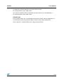
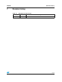
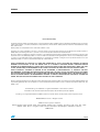
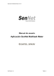
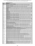
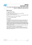
UM0289
User manual
eMotion: a motion control kit based on ST10F276
Introduction
This user manual describes the features of the eMotion Kit, and explains how use the kit to
perform generic speed control of DC and BLDC motors.
Figure 1.
eMotion kit
Key features
■
GUI software (Windows XP OS-compatible)
■
Control board MDK-ST10 (ST10F276 core, 16-bit DSP @ 64 MHz)
■
Shielded interface board (for encoder feedback)
■
powerSPIN boards (L6205 / L6235 eval)
■
Configurable PID closed speed loop for up three motors DC or BLDC
■
RS232 communication
November 2006
Rev 1
1/29
www.st.com
Contents
UM0289
Contents
1
Overview . . . . . . . . . . . . . . . . . . . . . . . . . . . . . . . . . . . . . . . . . . . . . . . . . . 3
1.1
2
Hardware . . . . . . . . . . . . . . . . . . . . . . . . . . . . . . . . . . . . . . . . . . . . . . . . . . 5
2.1
MDK-ST10 . . . . . . . . . . . . . . . . . . . . . . . . . . . . . . . . . . . . . . . . . . . . . . . . . 5
2.2
PowerSPIN boards . . . . . . . . . . . . . . . . . . . . . . . . . . . . . . . . . . . . . . . . . . . 7
2.3
3
5
2.2.2
L6235 Eval board (BLDC Motor) . . . . . . . . . . . . . . . . . . . . . . . . . . . . . . . 8
Feedback board . . . . . . . . . . . . . . . . . . . . . . . . . . . . . . . . . . . . . . . . . . . . . 9
eMotion GUI . . . . . . . . . . . . . . . . . . . . . . . . . . . . . . . . . . . . . . . . . . . . . . . 12
3.1.1
EVAL 6235 window . . . . . . . . . . . . . . . . . . . . . . . . . . . . . . . . . . . . . . . . 12
3.1.2
EVAL 6205 window . . . . . . . . . . . . . . . . . . . . . . . . . . . . . . . . . . . . . . . . 14
3.1.3
Log window . . . . . . . . . . . . . . . . . . . . . . . . . . . . . . . . . . . . . . . . . . . . . . 16
4.1
Communication protocol . . . . . . . . . . . . . . . . . . . . . . . . . . . . . . . . . . . . . . 17
4.2
Control algorithm . . . . . . . . . . . . . . . . . . . . . . . . . . . . . . . . . . . . . . . . . . . 21
Using eMotion . . . . . . . . . . . . . . . . . . . . . . . . . . . . . . . . . . . . . . . . . . . . . 23
Evaluate eMotion kit . . . . . . . . . . . . . . . . . . . . . . . . . . . . . . . . . . . . . . . . . 23
5.1.1
Installing eMotion GUI . . . . . . . . . . . . . . . . . . . . . . . . . . . . . . . . . . . . . . 23
5.1.2
Board configuration . . . . . . . . . . . . . . . . . . . . . . . . . . . . . . . . . . . . . . . . 23
5.1.3
Control operations . . . . . . . . . . . . . . . . . . . . . . . . . . . . . . . . . . . . . . . . . 24
Limitations . . . . . . . . . . . . . . . . . . . . . . . . . . . . . . . . . . . . . . . . . . . . . . . . 26
6.1
7
L6205 Eval board (DC Motor) . . . . . . . . . . . . . . . . . . . . . . . . . . . . . . . . . 7
ST10 firmware . . . . . . . . . . . . . . . . . . . . . . . . . . . . . . . . . . . . . . . . . . . . . 17
5.1
6
2.2.1
PC software . . . . . . . . . . . . . . . . . . . . . . . . . . . . . . . . . . . . . . . . . . . . . . . 12
3.1
4
Getting started . . . . . . . . . . . . . . . . . . . . . . . . . . . . . . . . . . . . . . . . . . . . . . 3
Hardware issues . . . . . . . . . . . . . . . . . . . . . . . . . . . . . . . . . . . . . . . . . . . . 26
Revision history . . . . . . . . . . . . . . . . . . . . . . . . . . . . . . . . . . . . . . . . . . . 27
Appendix A Bibliography . . . . . . . . . . . . . . . . . . . . . . . . . . . . . . . . . . . . . . . . . . . . 28
2/29
UM0289
Overview
1
Overview
1.1
Getting started
eMotion is a motion control kit able to manage up to 3 motors (DC or BLDC) simultaneously,
it can be used as starting point for the evaluation of control algorithms, motors and drivers.
The complete kit is composed of:
●
Windows GUI (XP-compatible): a Multi-Windows software for managing, through a
serial connection, the control of up three motors.
●
MDK-ST10 board: control board based on microcontroller ST10F276 and three
connectors compatible with a powerSPIN board (eval 62xx)
●
Interface board: a board with two shielded connectors, to be stacked into the sockets of
MDK-ST10 to allow motor feedback of encoder signals.
●
powerSPIN boards: the eMotion kit can manage up to three motor driver boards based
on L6205 (DMOS dual full bridge motor driver) and L6235 (DMOS fully integrated
three-phase motor driver) chips, for DC and BLDC motors respectively.
●
Firmware for open/closed loop operation: a complete source library is developed to
manage the control of DC and BLDC motors in open loop mode (PWM and driver
settings) and closed loop mode (speed regulation with encoder feedback) using 62xx
eval boards.
●
Protocol communication: a complete frame-based protocol is developed to allow the
exchange of data with GUI via standard RS232 channel.
Figure 2.
eMotion kit block diagram
RS232
Serial
Protocol
PC + GUI
Encoder
signals
Control
board MDK
ST10
PWM/
Driver
Board
Power
Encoder
signals
Feedback
board
(shielded)
PowerSPIN
boards
BLDC or
DC
motors
Power
signals
Driver
Power
It is possible via the GUI to interact with the ST10F276 control board (MDK-ST10) and
generate open loop signals for up three DC or BLDC motors. The PWM frequency (17-30
kHz) and duty cycle (0-100%) can be managed together with driver signals such as
enable/disable, brake/unbrake (BLDC) and forward/reverse (DC).
The closed loop operation can be performed in terms of motor speed with encoder
feedback.
A complete PID (Proportional, Integrative, And Derivative) control algorithm is implemented.
The user can configure:
●
the value of PID terms (from 0.01 to 100)
●
the speed (from 1 to 3000 rpm)
●
the control loop time (from 1 to 52 ms)
●
the number of encoder pulses per revolution (1 to 65536)
3/29
Overview
UM0289
Encoder feedback signals are directly managed by the ST10F276 through its dedicated
peripherals.
In order to guarantee an optimum quality of encoder waveforms, a special adapter is
included to shield the signals and to avoid interference (refer to Section 2.3 on page 9 for
further information).
4/29
UM0289
Hardware
2
Hardware
2.1
MDK-ST10
(Refer to the MDK-ST10 User manual (UM0288) for more detailed information)
The core of the eMotion Kit is the control board which is based on the ST10F276
microcontroller, in which all the driver board management routines are implemented.
Board key features:
●
ST10F276 core (16-bit with DSP @ 64 MHz, 832 KB Flash,68 KB RAM)
●
RS232
●
RS485
●
2 CAN
●
I2C (3.3V and 5V)
●
MC Connector
●
3 powerSPIN connectors
●
VN808 board / GP connector
●
All pin outs available
The board design allows the user to develop a high-end motion control system based on this
16-bit microcontroller. The features of this powerful device allow the integration of complex
routines to create advanced motion control algorithms.
Referring on Figure 2, the eMotion kit uses the connectors PowerSpin_1, 2, 3 as indicated
on the silkscreen of the board with the text "PractiSpin 1", "PractiSpin 2", "PractiSpin 3".
To allow the compatibility with powerSPIN evaluation boards, for each board connector is
inserted a jumper (VCC PRACTI X, located close to the connector) that, if closed, provides
a 5V power supply to the respective board.
Communication with a PC and GUI system is achieved via an RS232 channel through a
standard DB9 female connector and using a standard RS232 cable.
5/29
Hardware
UM0289
Figure 3.
MDK-ST10 board
POWERSPIN_1
CAN1
MC_CONNECTOR
POWERSPIN_2
ST10F276
CAN2
VN808 / GP
2
I C
RS485
POWERSPIN_3
RS232
Note:
Refer also to Section 5.1.2: Board configuration on page 23
The default configuration of the board (once programmed) is:
●
EA jumper: 1 (in order to obtain the fetch of the code from internal flash of
microcontroller)
●
SW3 switches: all OFF
●
SW5 switches:
–
●
Switch 2 (CSEL 0): ON
–
Switch 7 (CLK 1): ON
–
Other switches: OFF
Selector J206: "PRACTI" position (in order to connect micro lines to powerSPIN
connectors)
These configurations impose a 60 MHz core clock frequency and leave port 6 of
microcontroller free for I/0s (needed because P6.0=CS0 is used to manage powerSPIN
boards)
To better understand how powerSPIN boards are managed by control board, Table 1
provides a description of the powerSPIN connectors:
6/29
UM0289
Hardware
Table 1.
PractiSPIN connectors description
PIN No.
2.2
PractiSPIN 1
PractiSPIN 2
PractiSPIN 3
Functionality
1
5V via Jumper
J207 (VCC
PRACTI 1)
5V via Jumper
J208 (VCC
PRACTI 2)
5V via Jumper
J209 (VCC
PRACTI 3)
-
2
P2_10
P2_11
P2_12
Interrupt
3
P5_5
P5_6
P5_7
ADC
4
P0L.0
P0L.1
P0L.2
GPIO
5, 6
NC
NC
NC
-
7
P1L.0
P1L.1
P1L.2
ADC
8
P0L.3
P0L.4
P0L.5
GPIO
9
NC
NC
NC
-
10
P0L.6
P0L.7
P6.3
GPIO
11, 13
NC
NC
NC
-
14
P6.0
P6.1
P6.2
GPIO
15, 16, 17, 18, 19
NC
NC
NC
-
20
P2.0
P2.1
P2.2
GPIO / Capcom
21
NC
NC
NC
-
22
P8.0
P8.1
P8.2
PWM / GPIO
23
GND
GND
GND
-
24, 25
NC
NC
NC
-
26
P7.4
P7.5
P7.6
GPIO / Capcom
27
NC
NC
NC
-
28
P7.0
P7.1
P7.2
PWM / GPIO
29, 30
NC
NC
NC
-
31
P2.13
P2.14
P2.15
GPIO / Capcom
32
P2.3
P2.4
P2.5
GPIO / Capcom
33
P1H.4
P1H.5
P1H.6
GPIO / Capcom
34
NC
NC
NC
-
PowerSPIN boards
eMotion kit can manage up to three boards based on monolithic driver of L62xx family. This
first release of system works with DC and BLDC drivers so with boards L6205 and L6235
but also with similar boards for the same motors.
2.2.1
L6205 Eval board (DC Motor)
(refer to application note AN1762 and the L620x datasheet for more details)
7/29
Hardware
UM0289
eMotion kit can manage the evaluation board based on DMOS full bridge ICs
(L6205,L6206,L6207).
Figure 4.
Eval 6205N board
Refer to Section 5.1.2: Board configuration on page 23 for a description of the board
configuration using eMotion.
2.2.2
L6235 Eval board (BLDC Motor)
(refer to application note AN1625 and the L6235 datasheet for more details)
eMotion kit can manage the evaluation board based on L6235 three phase brushless DC
motor.
Figure 5.
Eval 6235 board
Refer to Section 5.1.2: Board configuration on page 23 for a description of the board
configuration using eMotion.
8/29
UM0289
2.3
Hardware
Feedback board
In order to interface the control system with encoder signals coming from motors, a special
board, with two 20 pins connectors in the top side, is used (Feedback board).
This is a stackable board and has to be inserted using the four 36-pin connectors around the
microcontroller in the MDK-ST10 board. The insertion orientation is indicated with a dot in a
corner of the board (corresponding to pin 1 of the ST10 MCU)
The two connectors (Conn1 J3, Conn2 J4), used to allow the encoder feedback, are
shielded with the pair of pins connected to GND.
The dimensions of this board are about 6.5 x 6.5 cm. The following tables show the pin
assignments for each connector.
Table 2.
Conn1 Feedback board
Conn.1
MDK-ST10 Pin
Functionality
1
P3.7
T2IN (encoder_1 A)
2
GND
-
3
P5.15
T2EUD (encoder_1 B)
4
GND
-
5
P3.6
T3IN (encoder_2 A)
6
GND
-
7
P3.4
T3EUD (encoder_2 B)
8
GND
-
9
P3.5
T4IN (encoder_3 A)
10
GND
-
11
P5.14
T4EUD (encoder_3 B)
12
GND
-
13
P2.6
CC16 (capture / GPIO)
14
GND
-
15
P1L.3
GPIO / ADC In
16
GND
-
17
P1L.4
GPIO / ADC In
18
GND
-
19
+5V
-
20
GND
-
Table 3.
Conn2 Feedback board
Conn.2
MDK-ST10 Pin
Functionality
1
P1L.5
GPIO/ ADC In
2
GND
-
3
P2.7
CC7 (capture / GPIO)
9/29
Hardware
UM0289
Conn.2
Functionality
4
GND
-
5
P1L.6
GPIO / ADC In
6
GND
-
7
P1L.7
GPIO / ADC In
8
GND
-
9
P1H.0
GPIO
10
GND
-
11
P1H.7
CC27 (capture / GPIO)
12
GND
-
13
P1H.1
GPIO
14
GND
-
15
P1H.2
GPIO
16
GND
-
17
P1H.3
GPIO
18
GND
-
19
+5V
-
20
GND
-
Figure 6.
10/29
MDK-ST10 Pin
Feedback board schematic
UM0289
Hardware
Figure 7.
Feedback board - TOP
In order to report the feedback of motors, a 20-pin flat cable could be used. The first
connector can be used for an incremental encoder as the timer pins are used for
incremental interface mode. The second connector can be used for absolute encoder
feedback where the GPIO and capture pins are used.
Note:
The system allows the feedback of encoder signals (A and B channels) for each motor,
Signals must be squared and with the right logic level (0 and 5V). When necessary, refer to
the datasheet of the encoder used. If needed, pull-up the encoder signals (not provided with
encoder kit).
11/29
PC software
3
UM0289
PC software
The parameters of eMotion system can be configured through a Windows-based GUI
(eMotion GUI), that interacts with the control board via an RS232 straight cable.
The following paragraphs provide a description of all the software features.
3.1
eMotion GUI
Refer to Section 5.1.1: Installing eMotion GUI on page 23 for the installation procedure.
After start-up of the eMotion GUI, a series of menu functions are available to the user:
File:
Connect: Open the "Serial Port Selection" window, from which it is possible to select the
serial port to open the communication between the PC and the MDK-ST10 board
Disconnect: Close the connection between the PC and the MDK-ST10 board.
New: Open a new 6205 or 6235 window (for a DC or BLDC motor respectively)
Log Window: Open the Log Window. In this window it is possible to see the communication
data as a hexadecimal value sent to the MDK-ST10 board
Exit: Exit the program
View:
Toolbar: Display or hide the toolbar
Status Bar: Display or hide the status bar in the bottom-right corner of the main window
Help
Help Topics: Open the Help Topics
About: Displays eMotion Project credits
3.1.1
EVAL 6235 window
The 6235 window allows the user to drive a BLDC motor through the EVAL6235 board. After
starting eMotion, click on the 6235 window icon or choose New - 6235 window from the
File menu. A new 6235 window opens.
12/29
UM0289
PC software
Figure 8.
6235 window
The Connector Selection panel shows the connector of the MDK-ST10 with which the
EVAL6235 can be connected (some connector selections could be disabled if the connector
is used by other windows). The left part of this window allows the user to control a BLDC
motor in open loop mode. The right part of the window allows the user to perform a PID
speed closed loop control with encoder feedback.
The Motor Control Command panel is always enabled, while the Control Parameters and
Control Loop Time panels are disabled when the Closed Loop check button is not checked.
In each case the Get button is always enabled.
Motor Control Command panel:
Note:
●
Enable: Enables the 6235 driver. This command switches ON all Power MOSFETs of
the driver (pin EN high).
●
Disable: Disables the 6235 driver. This command switches OFF all Power MOSFETs of
the driver (pin EN low).
●
Unbrake: Sets the pin BRAKE high of the 6235 and enables the normal mode (six step
control strategy).
●
Brake: Sets the pin BRAKE low of the 6235. This command switches ON all High Side
Power MOSFETs, implementing the Brake Function.
●
Duty Cycle Set: This slider allows the user to set the duty cycle of the PWM generated
by the ST10 as input for the FWD/REV pin of the 6235 driver. Values between 0 and
50% cause the rotation of the motor in one direction, while values between 50% and
100% cause the rotation of the motor in the other direction. A 50% value corresponds
to no motor rotation.
The real direction (clockwise or counterclockwise) depends on the connection between the
6235 and the motor.
●
Note:
PWM set: This slider allows the user to change the frequency of the PWM generated by
the ST10. The allowed values go from a minimum of 17 kHz to a maximum of 30 kHz.
(with 1 kHz steps)
At system startup the default values are: disable, brake, PWM duty cycle 50%, PWM
frequency 17 kHz.
13/29
PC software
UM0289
Enable/Disable Control Parameters panel:
●
Closed Loop: This check control enables/disables the text boxes and push buttons of
the Control Parameters and Control Loop Time panels.
Control Parameters panel:
This panel allows the user to perform a PID speed closed loop control with encoder
feedback. The user must fill the following text boxes and then press the Set button in order
to set the control parameters:
Note:
●
Enc. Pulses/r: The number of pulses per revolution of motor encoder.
●
Speed: Speed of the motor expressed in RPM. Allowed values go from 0 to 3000 rpm
(steps 1 rpm).
●
P: Proportional gain of the PID control. Allowed values go from 0 to 100, in steps of
0.01.
●
I: Integral gain of the PID control. Allowed values go from 0 to 100, in steps of 0.01.
●
D: Derivative gain of the PID control. Allowed values go from 0 to 100, in steps of 0.01.
●
Set: Set the control parameters.
If values out of range are inserted in one or more text boxes, a pop-up window will appear
indicating that at least one value is out of range.
●
Start: Start the PID speed closed loop control. The rotation of the motor remains the
same of the motor before starting the control.
●
Stop: Stop the PID speed closed loop control. The motor will rotate with a speed
accordingly to the duty cycle calculated in the last control routine before stopping.
●
Get: This command returns the status of the control parameters and of the control loop
time actually memorized in the MDK-ST10 board.
Control loop time:
This text box allow the user to insert the value of control loop time (in case of closed loop
operation); the range of this parameter is from 1 to 52 ms (with 200 us steps)
Note:
For control loop time is intended the frequency of adjustment of PWM duty cycle (according
to PID action) in order to reach the speed reference.
3.1.2
EVAL 6205 window
The 6205 window is designed to allow the user to drive a DC motor through EVAL6205.
After starting eMotion click on the 6205 window icon or choose New - 6205 window from the
File menu. A new 6205 window is now opened.
Note:
14/29
The functions of this window are the same of 6235 window, except for the motor control
panel.
UM0289
PC software
Figure 9.
6205 window
The Connector Selection panel shows the connector of the MDK-ST10 with which the
EVAL6205 can be connected (some connector selections could be disabled if the connector
is used by other windows). The left part of this window allows the user to control a DC motor
in open loop mode. The right part of the window allows the user to perform a PID speed
closed loop control with encoder feedback.
The Motor Control Command panel is always enabled, while the Control Parameters and
Control Loop Time panels are disabled when the Closed Loop check button is not checked.
In each case the Get push button is always enabled.
Motor Control Command panel:
Note:
●
Enable: Enables the 6205 driver. This command switches ON all Power MOSFETs of
the driver (pin EN high).
●
Disable: Disables the 6205 driver. This command switches OFF all Power MOSFETs of
the driver (pin EN low).
●
Forward: This command set low the pin IN1 of the EVAL6205 (pin IN1A of 6205 driver).
●
Reverse: This command set high the pin IN1 of the EVAL6205 (pin IN1A of 6205
driver).
●
Duty Cycle Set: This slider allows the user to set the duty cycle of the PWM generated
by the ST10 as input for the IN2 of the EVAL6205 (pin IN2A of the 6205 driver).The
direction of rotation of the motor depends on the Forward/Reverse radio buttons. If
Forward (Reverse) radio button is checked a value of PWM of 0% (100%) stops the
motor while a value of PWM of 100% (0%) runs the motor at maximum velocity.
The real direction (clockwise or counterclockwise) depends on the connection between the
6205 and the motor.
●
Note:
PWM set: This slider allows the user to change the frequency of the PWM generated by
the ST10. The allowed values go from a minimum of 17 kHz to a maximum of 30 kHz
(steps 1 kHz).
At systems startup the default value are: disable, forward, PWM duty cycle 50%, PWM
frequency 17 kHz.
Enable/Disable Control Parameters panel:
Refer to Section 3.1.1: EVAL 6235 window on page 12.
15/29
PC software
UM0289
Control Parameters panel:
Refer to Section 3.1.1: EVAL 6235 window on page 12.
Control loop time:
Refer to Section 3.1.1: EVAL 6235 window on page 12.
3.1.3
Log window
Using the log window is possible to view the frames sent and received by the GUI (to check
the state of communication with the board).
A text string is shown explaining the command and also the hexadecimal value of the
command (refer to Section 4.1: Communication protocol on page 17).
Figure 10. Log window
16/29
UM0289
4
ST10 firmware
ST10 firmware
The firmware to manage the eMotion system is organized in two separate modules:
●
Communication module: able to exchange data with the PC-GUI using a structured
protocol.
●
Control module: able to perform the open and closed loop operation on three motors
and communicates with the first module.
Note:
All the firmware is developed, in standard C language, using tasking toolchain v 8.5 from
Altium.
4.1
Communication protocol
The serial protocol used for communicate with PC-GUI is a frame based protocol, with a
baud rate of 115200, 8-bit data length, no parity check, 1 bit stop.
The frame has a variable length, with a CRC field. A mechanism of acknowledgement for
each command is implemented.
Figure 11. Frame protocol
Frame Type
Length
1 byte
Payload
1 byte
variable length
CRC
1 byte
Figure 11 shows the general frame format on which the communication is based, the CRC is
a field of 1 byte length computed with this formula:
16_Total_Length = (16_bit) (FRAME_TYPE + LENGTH + DATA)
CRC = (8_bit) (High_Byte(16_Total_Length) + Low_Byte(16_Total_Length))
Table 4 shows the general description of the frames.
Table 4.
Frame description
Frame name
Description
Frame Type
Length
Direction
Type
Connect
Open
connection
0x00
0
PC-MDK ST10 Command
Enable_Motor
Enable motor
drive
0x01
1
PC-MDK ST10 Command
Disable_Motor
Disable motor
drive
0x02
1
PC-MDK ST10 Command
Brake_Motor
Enable brake
motor drive
0x03
1
PC-MDK ST10 Command
Unbrake_Motor
Disable brake
motor drive
0x04
1
PC-MDK ST10 Command
Forward_Motor
Set forward
motor direction
0x05
(6205 motor
drive)
1
PC-MDK ST10 Command
17/29
ST10 firmware
UM0289
Frame name
Description
Frame Type
Length
Direction
Type
Reverse_Motor
Set reverse
motor direction
0x06
(6205 motor
drive)
1
PC-MDK ST10 Command
Set_PWM
Set duty cycle
0x07
of PWM
2
PC-MDK ST10 Command+Data
Set_Freq_PWM
Set frequency
of PWM
0x08
2
PC-MDK ST10 Command+Data
Set_PID_Contr
ol
Set the PID
and speed
values
0x09
12
PC-MDK ST10 Command+Data
Set_Control
_Loop Time
Set the time for
executing the
0x0A
closed control
loop
2
PC-MDK ST10 Command+Data
Get_Parameter
s
Get the control
0x0B
parameters.
1
PC-MDK ST10 Command
Start_Control
Start control
loop
0x0C
1
PC-MDK ST10 Command
Stop_Control
Stop control
loop
0x0D
1
PC-MDK ST10 Command
Get_Latest_Err
or
Get Latest
error occurred
0x0E
0
PC-MDK ST10 Command
Send_Paramet
ers
Transmission
of the
parameters
values
0x40
15
MDK ST10-PC Data
Send_Latest_E Send latest
rror
error occurred
0x41
1-50
MDK ST10-PC Data
Confirm the
correct
reception of a
frame
0x80
1
MDK ST10-PC
Acknowledgment
PC-MDK ST10
ACK
The length field indicated the number of bytes in the payload.
In each frame (with length greater than 0) the first byte of the payload indicates the
association connector-powerspin board (except "Send_Latest_Error") (see Table 5):
Table 5.
Connector-Eval62xx
Byte
18/29
Value
0x1A
First connector with eval 6235
0x1B
First connector with eval 6205
0x2A
Second connector with eval 6235
0x2B
Second connector with eval 6205
UM0289
ST10 firmware
Byte
Value
0x3A
Third connector with eval 6235
0x3B
Third connector with eval 6205
ACK timeout is fixed at 10 ms, both for the PC and ST10, and the payload of the "ACK"
frame is the command code to be acknowledged.
"Set_PID_Control" (0x09) is the frame used for setting the specific values of each control
loop, the contents of this frame is shown in the table below.
Table 6.
Table 6 - Set_PID_Control payload
Payload
byte order
Field
Description
1
Motor Connector
Association connector-powerSPIN board
2
Driver
Byte for reserved use, indicating the kind of driver
(0xCD for a6205,0xEB for a 6235)
3-4
Encoder
2 Bytes indicating number of pulse for revolution of
motor encoder.
5-6
Speed
2 Bytes indicating the reference speed of motor
(range 1-3000 rpm)
7-8
P
2 Bytes indicating the proportional gain of the
speed control (range 1-1000, with a firmware
scaling)
9-10
I
2 Bytes indicating the integral gain of the speed
control (range 1-1000, with a firmware scaling)
11-12
D
2 Bytes indicating the derivative gain of the speed
control (range 1-1000, with a firmware scaling)
"Set_Control_Loop time" (0x0A) is a frame used to set the control loop time of each motor
control, according to the table below.
Table 7.
Set_Control loop time payload
Payload
byte order
Field
Description
1
Motor Connector
1 Byte indicating which powerSPIN board is connected
to a specific connector.
2
Time
Byte indicating the control loop time (number of 200us
steps to be added to the basic control loop of 1ms).
"Send_Parameters" (0x40) is a particular frame used to send the status of all system
parameters to the PC, the contents of this frame is shown in Table 8.
19/29
ST10 firmware
UM0289
Table 8.
Send_Parameters contents
Payload
Field
byte order
Description
Motor Connector
1 Byte indicating which powerSPIN board is connected to
a specific connector.
2-3
Encoder
2 Bytes indicating the number of pulses for revolution of
motor encoder.
4
PWM %
Byte indicating the duty cycle value of PWM (range: 0100)
5
PWM Freq.
Byte indicating the frequency PWM (range: 17-30)
6
Time control loop
Byte indicating the control loop time (number of 200us
steps to be added to the basic control loop of 1ms).
7
Status
Byte indicating if the control is enabled (0 or 1)
8-9
Speed
2 Bytes indicating the reference speed of motor (range 13000 rpm)
10-11
P
2 Bytes indicating the proportional gain of the speed
control (range 1-1000, with a firmware scaling)
12-13
I
2 Bytes indicating the integral gain of the speed control
(range 1-1000, with a firmware scaling)
14-15
D
2 Bytes indicating the derivative gain of the speed control
(range 1-1000, with a firmware scaling)
1
"Send latest error" (0x41) is a particular frame in which the payload is formed by a text string
indicating the last error occurred, typical values are shown below.
Table 9.
Error strings
String Types
No error
CRC not valid
Command not valid
Command not executable
Motor error
Value out of range
A series of protocol frames, used for communication, are provided in Table 10.
Table 10.
Frame examples
Frame Description
20/29
Value (Hex)
Connect
00-00-00
Enable 6235 driver on powerSPIN connector 1
01-01-1A-1C
Brake 6205 driver on powerSPIN connector 3
03-01-3B-3F
ACK for a Forward command
80-01-05-86
UM0289
ST10 firmware
Frame Description
Value (Hex)
Set PWM% to 22% for 6235 driver on connector 2
08-02-2A-16-4A
Set 2ms of control loop time for a 6205 driver on connector 2
0A-02-2B-05-3C
Set control for a DC motor with a 1024/revolution encoder,
09-0C-1B-CD-04-00-00-64-00-04connected to the first connector. Set the speed reference to 100
00-02-00-01-6D
rpm with control parameters of P=0.04,I=0.02,D=0.01
Receive the parameters of connector 3 with a BLDC motor with
500/revolution encoder controlled at 200 rpm with P=0.60,
40-0F-3A-01-F4-00-0A-16-02-01I=0.02,D=0.00 and control loop of 1.2 ms. With actual PWM
00-C8-00-3C-00-02-00-00-A9
signal 10% / 22 Khz
4.2
Control algorithm
Communication layer after the reception and checking of a complete frame puts the
microcontroller in an execution state in which the right control layer function is involved.
The management of open loop signals is executed with functions that directly act in the
register of PWM signals or through the pins for the right generation of connector signals.
Closed loop operations, are instead managed through three independent ISR where the
reload timing depends on the closed loop time of the specific control.
The speed reference is expressed in terms of encoder pulses, counted in the closed loop
timing imposed, so each ISR works with the actual values of encoder inputs and with PWM
duty cycles to perform a PID action for reach the right value of encoder reference.
Figure 12. Algorithm block diagram
Communication
Layer
Shared
memory
Control
Layer
SERIAL BUFFER
Figure 12 shows how the two modules interact (through shared memory) to perform
eMotion operations.
The PID algorithm implemented is approximated with the following formula:
n
u (n) = P ⋅ e(n) + I ⋅ ∑ ⋅e(k ) ⋅ T + D ⋅
K =1
e(n) − e(n − 1)
T
21/29
ST10 firmware
UM0289
where:
u(n): is the output at time n (related to the duty cycle sent to driver)
P, I, D: are respectively proportional gain, integrational gain and derivative gain.
e : is the error (in terms of encoder pulses)
T : is the sample time
22/29
UM0289
Using eMotion
5
Using eMotion
5.1
Evaluate eMotion kit
In order to start eMotion system all this items should be available:
5.1.1
●
eMotion GUI
●
MDK-ST10 board
●
Feedback board
●
At least 1 powerSPIN board (Eval 6205 / Eval 6235)
●
At least 1 BLDC or 1 DC motor (respectively to be used with Eval 6205 or Eval 6235)
●
eMotion firmware
Installing eMotion GUI
To install the eMotion GUI, launch the setup file named eMotion_GUI_XX_Setup.exe. After
the acceptance of the license agreement, a new menu item (STMicroelectronics \ eMotion )
will be created; use this link to launch the software.
The eMotion software is compatible with the Windows XP OS.
5.1.2
Board configuration
MDK-ST10:
ST10 FLASHING: The first operation to perform, before starting to use eMotion kit, is to
flash ST10 microcontroller with eMotion firmware; in order to achieve this task, ST10Flasher
(V2.4B or above) software has to be used (i.e. a software windows compatible useful to
program the internal flash of ST10).
Connect MDK-ST10 to PC via a RS232 straight cable and puts ST10 in BSL mode (turn on
bit 5 of switch 3 and reset the board). Using ST10Flasher, load file named "emotion.hex"
and perform the flashing of microcontroller, so turn off bit 5 of switch 3 and reset the board.
Now MDK-ST10 is ready to be used with eMotion kit (EA jumpers has to be switched to 1)
J206 jumpers: In order to use the power spin boards, J206 jumpers have to placed in
"Practi" position.
VCC Practi X Jumpers: leave open the Jumper VCC Practi1,VCC Practi2 and VCC Practi3.
SW3: All OFF
SW5: CSSEL0 ON,CLK1 ON, all the remains bits OFF.
Feedback board:
Connect the feedback board to the four expansion connectors of MDK-ST10 (the connectors
surrounding microcontroller).
The correct connection for incremental encoder of motors is shown in Table 11
23/29
Using eMotion
UM0289
Table 11.
Feedback connector
MDK-Connector/ Motor Value
Feedback board connector
Motor on Practi 1 encoder A
Connector 1 (J3), Pin 1
Motor on Practi 1 encoder B
Connector 1 (J3), Pin 3
Motor on Practi 2 encoder A
Connector 1 (J3), Pin 5
Motor on Practi 2 encoder B
Connector 1 (J3), Pin 7
Motor on Practi 3 encoder A
Connector 1 (J3), Pin 9
Motor on Practi 2 encoder B
Connector 1 (J3), Pin 11
The use of a flat cable is recommended to keep the signals shielded.
Eval 6205 configuration:
JP1: Place JP1 in the INT position to enable the on-board 5VDC supply.
JP2 and JP3: Install JP2 and JP3 to assure proper timing operation of the L6205's internal
high side overcurrent protection.
JP4 and JP5: Install JP4 and JP5 to configure the Vref circuits.
Supply the power to eval 6205 through connector CN1.
Connect the DC motor through CN3 connector (OUT1A and OUT2A).
Refer to the L6205 datasheet for more detailed information
Note:
For each EVAL 6205 board eMotion kit allows to connect and control one motor.
Eval 6235 configuration:
JP1 and JP2: Install JP1 and JP2 to enable the on-board 5VDC supply.
SWITCHES: Place all four switches in the OFF position.
HALL SENSORS: Connect the Hall sensors of the BLDC motor at CN5. Connect the power
supply wires from the Hall sensors at pins GND and 5V. Connect H1, H2, and H3 signals to
their respective pins.
Motor Connections: Connect the three motor armature wires at CN3 being careful to match
the phasing to the Hall sensor connections.
Refer to L6235 datasheet for more detailed information.
To connect the power spin boards use a flat 34-pin cables and before power on all the
systems (motors and boards) please refer to Section 6.1: Hardware issues on page 26.
5.1.3
Control operations
Before starting to use the motors, ensure that all the connection are correctly established.
Turn on MDK-ST10 and later turn the power of motors.
Open Loop
For a DC: enable the driver and modify the PWM in terms of DUTY % (depending on the
motor connection, a 0 value corresponds to either the minimum or the maximum speed).
24/29
UM0289
Using eMotion
The direction of rotation depends on the connection of motor.
At startup the Duty cycle is fixed at 50 %
For a BLDC: enable the driver and unbrake the motor. Start to vary the PWM Duty %
At startup the Duty cycle is fixed at 50 %
Closed Loop
The parameter values of P, I and D depend on the type of motor and the suggestion is to
start with lower values and increment them in order to reach better performance.
At low speeds it is recommended to use a high control loop time.
25/29
Limitations
6
UM0289
Limitations
This section provides tips for use of the eMotion system to avoid incorrect operation.
6.1
Hardware issues
Due to the sharing of some microcontroller configuration pins with the powerSPIN
connectors (P0L.0 and P0L.1), the reset phase, when a L6235 evaluation board is
connected through the "practi1" or "practi2" connectors causes the micro to enter "ADAPT"
or "EMU" modes (when a pull-up is used).
A feature release (v 1.2) of MDK-ST10 will include a series of buffers to isolate these pins
from connectors during the reset phase.
26/29
UM0289
7
Revision history
Revision history
Table 12.
Document revision history
Date
Revision
30-Nov-2006
1
Changes
Initial release.
27/29
Bibliography
UM0289
Appendix A
28/29
Bibliography
●
AN1794 Application Note, "PractiSpin evaluation system configuration and setup
guide".
●
L6205 datasheet
●
L6235 datasheet
●
UM0288, MDK-ST10 user manual
UM0289
Please Read Carefully:
Information in this document is provided solely in connection with ST products. STMicroelectronics NV and its subsidiaries (“ST”) reserve the
right to make changes, corrections, modifications or improvements, to this document, and the products and services described herein at any
time, without notice.
All ST products are sold pursuant to ST’s terms and conditions of sale.
Purchasers are solely responsible for the choice, selection and use of the ST products and services described herein, and ST assumes no
liability whatsoever relating to the choice, selection or use of the ST products and services described herein.
No license, express or implied, by estoppel or otherwise, to any intellectual property rights is granted under this document. If any part of this
document refers to any third party products or services it shall not be deemed a license grant by ST for the use of such third party products
or services, or any intellectual property contained therein or considered as a warranty covering the use in any manner whatsoever of such
third party products or services or any intellectual property contained therein.
UNLESS OTHERWISE SET FORTH IN ST’S TERMS AND CONDITIONS OF SALE ST DISCLAIMS ANY EXPRESS OR IMPLIED
WARRANTY WITH RESPECT TO THE USE AND/OR SALE OF ST PRODUCTS INCLUDING WITHOUT LIMITATION IMPLIED
WARRANTIES OF MERCHANTABILITY, FITNESS FOR A PARTICULAR PURPOSE (AND THEIR EQUIVALENTS UNDER THE LAWS
OF ANY JURISDICTION), OR INFRINGEMENT OF ANY PATENT, COPYRIGHT OR OTHER INTELLECTUAL PROPERTY RIGHT.
UNLESS EXPRESSLY APPROVED IN WRITING BY AN AUTHORIZED ST REPRESENTATIVE, ST PRODUCTS ARE NOT
RECOMMENDED, AUTHORIZED OR WARRANTED FOR USE IN MILITARY, AIR CRAFT, SPACE, LIFE SAVING, OR LIFE SUSTAINING
APPLICATIONS, NOR IN PRODUCTS OR SYSTEMS WHERE FAILURE OR MALFUNCTION MAY RESULT IN PERSONAL INJURY,
DEATH, OR SEVERE PROPERTY OR ENVIRONMENTAL DAMAGE. ST PRODUCTS WHICH ARE NOT SPECIFIED AS "AUTOMOTIVE
GRADE" MAY ONLY BE USED IN AUTOMOTIVE APPLICATIONS AT USER’S OWN RISK.
Resale of ST products with provisions different from the statements and/or technical features set forth in this document shall immediately void
any warranty granted by ST for the ST product or service described herein and shall not create or extend in any manner whatsoever, any
liability of ST.
ST and the ST logo are trademarks or registered trademarks of ST in various countries.
Information in this document supersedes and replaces all information previously supplied.
The ST logo is a registered trademark of STMicroelectronics. All other names are the property of their respective owners.
© 2006 STMicroelectronics - All rights reserved
STMicroelectronics group of companies
Australia - Belgium - Brazil - Canada - China - Czech Republic - Finland - France - Germany - Hong Kong - India - Israel - Italy - Japan Malaysia - Malta - Morocco - Singapore - Spain - Sweden - Switzerland - United Kingdom - United States of America
www.st.com
29/29