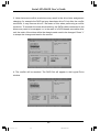
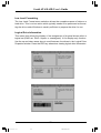
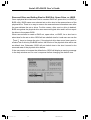
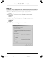
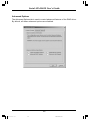
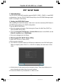
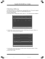
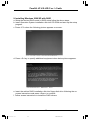
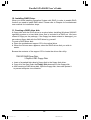
1
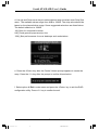
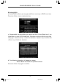
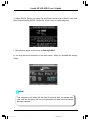
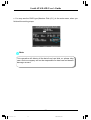
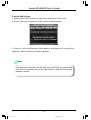
RAID User Guide Edition V1.0 P/N: 91-187-U25-A2-0E Trademarks All brand or product names mentioned are trademarks or registered trademarks of their respective holders. RAID Manual Preface.p65 1 2004-12-15, 9:01 Contents Intel ICH6R SATA RAID ........................................................................... 1 1. Introduction ................................................................................................. 1 2. Installing SATA Hard Disks ........................................................................ 3 3. BIOS Configuration .................................................................................... 3 4. RAID Configuration Utility .......................................................................... 3 5. Installing Windows 2000/XP with RAID .................................................. 13 6. Installing RAID Driver ............................................................................... 15 Silicon 3114 SATA RAID ........................................................................ 16 1. Introduction ............................................................................................... 16 2. SATARAID5 Features ................................................................................ 16 3. Installing Serial ATA (SATA) hard disks ................................................... 17 4. Setting the BIOS RAID items ................................................................... 17 5. Creating and Deleting RAID Sets ........................................................... 18 6. Installing Drivers and Software ............................................................... 27 7. Creating / Naming Partitions ................................................................... 29 8. Using Silicon Image SATA RAID GUI ....................................................... 32 ITE® 8212F RAID .................................................................................... 37 1. Introduction ............................................................................................... 37 2. Setting the BIOS RAID items ................................................................... 37 3. Entering the ITE® 8212F Setup Utility ...................................................... 37 4. Auto-configuring a RAID array .................................................................. 38 5. Defining a RAID array ............................................................................... 39 6. Deleting a RAID array ............................................................................... 40 7. Rebuilding a RAID array .......................................................................... 41 8. Viewing your RAID configuration ............................................................. 42 9. Installing Windows 2000/XP with RAID .................................................. 43 10. Installing RAID Driver ............................................................................. 44 11. Creating a RAID driver disk ................................................................... 44 RAID Manual Preface.p65 2 2004-12-15, 9:01 Serial ATA RAID User’s Guide Intel ICH6R SATA RAID 1. Introduction RAID (Redundant Array of Independent Disks) is a method of combining two hard disk drives into one logical unit. The advantage of an Array is to provide better performance or data fault tolerance. Fault tolerance is achieved through data redundant operation, where if one drives fails, a mirrored copy of the data can be found on another drive. This can prevent data loss if the operating system fails or hangs. The individual disk drives in an array are called members. The configuration information of each member is recorded in the reserved sector. That identifies the drive as a member. All disk members in a formed disk array are recognized as a single physical drive to the operating system. Hard disk drives can be combined together through a few different methods. The different methods are referred to as different RAID levels. Different RAID levels represent different performance levels, security levels and implementation costs. RAID 0 (Striping) RAID 0 reads and writes sectors of data interleaved between multiple drives. If any disk member fails, it affects the entire array. The disk array data capacity is equal to the number of drive members times the capacity of the smallest member. The striping block size can be set from 4KB to 128KB. RAID 0 does not support fault tolerance. RAID 1 (Mirroring) RAID 1 writes duplicate data onto a pair of drives and reads both sets of data in parallel. If one of the mirrored drives suffers a mechanical failure or does not respond, the remaining drive will continue to function. Due to redundancy, the drive capacity of the array is the capacity of the smallest drive. Under a RAID 1 setup, an extra drive called the “spare drive” can be attached. Such a drive will be activated to replace a failed drive that is part of a mirrored array. Due to the fault tolerance, if any RAID 1 drive fails, data access will not be affected as long as there are other working drives in the array. 1 RAID Manual.p65 1 2004-12-15, 9:04 Serial ATA RAID User’s Guide RAID 0+1 RAID 0+1 is a combination of striping and mirroring. This configuration provides optimal speed and reliablility, but you need four SATA hard disks. Matrix RAID Matrix RAID is a combination of RAID 0 and RAID 1 bringing you the best of both worlds. You only need two SATA hard disks to utilize this function. Advantages: 1. Faster data transfer 2. Improve the safety and stability of data 3. Swift and easy management for volume of data 2 RAID Manual.p65 2 2004-12-15, 9:04 Serial ATA RAID User’s Guide 2. Installing SATA Hard Disks STEP 1: Install two SATA hard disks into the drive bays at least. STEP 2: Connect one end of the SATA data cable to the motherboard’s one of SATA connectors. STEP 3: Connect the other end of the SATA data cable to one SATA hard disk. STEP 4: Connect one end of the second SATA data cable to the motherboard’s the other of SATA connectors. STEP 5: Connect the other end of SATA data cable to the other SATA hard disk. 3. BIOS Configuration 1. Enter the BIOS setup program by pressing the <Del> key during the POST (Power-On Self Test ). 2. Select the OnChip IDE Device item form Integrated Peripherals menu. 3. Switch the SATA Mode option to [RAID]. 4. Save the BIOS setting and exit the BIOS setup program. 4. RAID Configuration Utility A. Setting RAID 0 a. When the system powers on, the following information will appear on screen: Press the <Ctrl-I> to enter RAID Configuration Utility. At this moment, press <Ctrl>+<I> to enter Main Menu: 3 RAID Manual.p65 3 2004-12-15, 9:04 Serial ATA RAID User’s Guide b. Choose Create RAID Volume and press <Enter> to enter. Press <Tab> to switch to RAID Level item, and then use Up and Down arrow keys to select RAID0 (Stripe), pressing <Enter> confirms. c. Choose which two hard disks you want to set RAID 0 from Disks item, if you install three or more SATA hard disks. Otherwise continue with the next step. Using up or down arrow key to select the hard disk, <Space> key to confirm and <Enter> key to finish the selection. 4 RAID Manual.p65 4 2004-12-15, 9:04 Serial ATA RAID User’s Guide d. Use Up and Down arrow keys to select desired strip size when enter Strip Size menu. The available values range from 4KB to 128KB. The strip value should be based on the planned drive usage. Some suggested selections are listed below. The default selection is 128KB. 16K_Best for sequential transfer 64K_Good general purpose strip size 128K_Best performance for most desktops and workstations e. Press the <Enter> key after the Create Volume prompt appears to create the array. Press the <Y> key after the prompt to confirm this selection. f. Select option 4. Exit in main menu and press the <Enter> key to exit the RAID configuration utility. Press <Y> key to confirm the exit. 5 RAID Manual.p65 5 2004-12-15, 9:04 Serial ATA RAID User’s Guide B. Setting RAID1 a. Select RAID1 (Mirror) by using Up and Down arrow keys in RAID Level item. Press the <Enter> key to make selecting. c. Choose which two hard disks you want to set RAID 1 from Disks item, if you install three or more SATA hard disks. Otherwise continue with the next step. Using up or down arrow key to select the hard disk, <Space> key to confirm and <Enter> key to finish the selection. b. The following information will appear on screen: Press “Enter” to create the specified volume. Press the <Enter> key again to confirm. 6 RAID Manual.p65 6 2004-12-15, 9:04 Serial ATA RAID User’s Guide c. In below screen, press <Y> key to confirm your choice. d. Select option 4. Exit in main menu and press the <Enter> key to exit the RAID configuration utility. Press <Y> key to confirm the exit. Note: This operation will delete all the data from hard disk, so please take care. And our company will not be responsible for data lose and benefit damage caused. 7 RAID Manual.p65 7 2004-12-15, 9:04 Serial ATA RAID User’s Guide C. Setting RAID 0+1 a. To utilize RAID 0+1 function, four SATA hard disks should be installed. b. Choose Create RAID Volume and press <Enter> to enter. Press <Tab> to switch to RAID Level item, and then use Up and Down arrow keys to select RAID0 (Stripe), pressing <Enter> confirms. c. Using up and down arrow keys to select two hard disks for RAID 0, <Space> key to confirm and <Enter> key to finish the selection in the Disks item. d. The following steps is the same as Setting RAID 0. 8 RAID Manual.p65 8 2004-12-15, 9:04 Serial ATA RAID User’s Guide e. Select RAID1 (Mirror) by using Up and Down arrow keys in RAID Level item after finished setting RAID0. Press the <Enter> key to make selecting. f. The following steps is the same as Setting RAID 1. g. You may see the information in the main menu, when you finished the setting steps. Note: This operation will delete all the data from hard disk, so please take care. And our company will not be responsible for data lose and benefit damage caused. 9 RAID Manual.p65 9 2004-12-15, 9:04 Serial ATA RAID User’s Guide D. Setting Matrix RAID a. Intel ICH6R chipset features a new RAID form named Matrix RAID, a combination of RAID 0 and RAID 1 bringing you the best of both worlds. b. Follow Setting RAID 0 steps to set RAID 0. You should divide half capacity size or less for RAID 1 in Capacity item. (For example, if the SATA hard disks total capacity is 300 GB, divide 150 GB or less capacity for RAID 1.) c. Follow Setting RAID 1 steps to set RAID 1. 10 RAID Manual.p65 10 2004-12-15, 9:04 Serial ATA RAID User’s Guide c. You may see the RAID type (Member Disk (0,1)) in the main menu, when you finished the setting steps. Note: This operation will delete all the data from hard disk, so please take care. And our company will not be responsible for data lose and benefit damage caused. 11 RAID Manual.p65 11 2004-12-15, 9:04 Serial ATA RAID User’s Guide D. Delete RAID Volume 1. Select Delete RAID Volume in main menu and press <Enter> key. 2. Press <Del> key to delete the RAID volume in below screen. 3. Press <Y> key to confirm the volume deletion, and press <N> to cancel the operation, when following information appears. Note: This operation will delete all the data from hard disk, so please take care. And our company will not be responsible for data lose and benefit damage caused. 12 RAID Manual.p65 12 2004-12-15, 9:04 Serial ATA RAID User’s Guide E. Reset RAID 1. Select Reset Disk to Non-RAID in main menu and press <Enter> key to delete the RAID setting and remove all RAID structures from the drives. 2. Press <Y> key to confirm the volume deletion, press <N> to cancel the operation. 5. Installing Windows 2000/XP with RAID 1. Setup the desired RAID mode in BIOS setup follow the above steps. 2. Insert Operation System installation disk into CD-ROM and start up the setup program. 3. Press <F6> when the following picture appears on screen: 4. Press <S> key to specify additional equipment when below picture appears. 13 RAID Manual.p65 13 2004-12-15, 9:04 Serial ATA RAID User’s Guide 5. Insert the add-on RAID installation disk into floppy disk drive following the on-screen instructions and press <Enter> to continue. 6. Select the right choice and press <Enter> to continue. The choice is determined by South Bridge. 14 RAID Manual.p65 14 2004-12-15, 9:04 Serial ATA RAID User’s Guide 7. Press <Enter> to continue. 8. After this, the installation steps are the same as normal setup methods. No details are provided herein. 6. Installing RAID Driver When you finish installing Operation System with RAID, in order to enable RAID function you need to install RAID driver. Please refer to Chapter 4 of motherboard user manual for installation steps. 15 RAID Manual.p65 15 2004-12-15, 9:04 Serial ATA RAID User’s Guide SiIicon 3114 SATA RAID (optional) 1. Introduction Silicon Image’s SATARAID5TM software provides Serial ATA RAID 0 (Striping), RAID 1 (Mirroring), RAID 5 (Parity RAID), RAID 10 (Striping and Mirroring), and JBOD (just a bunch of disks) functionality to enhance the industry’s leading PCI-to-SATA host controller products. Two major challenges facing the storage industry today are keeping pace with the increasing performance demands of computer systems by improving disk I/O throughput and providing data accessibility in the face of hard disk failures while utilizing full disk capacity. With SiIicon Image Serial ATA host controller and SATARAID5, both of these problems are solved. SATARAID5 software provides a Graphical User Interface (GUI) for easy-to-use configurations of the RAID Groups. 2. SATARAID5 Features • RAID 0, RAID 1, RAID 5, RAID 10, and JBOD • Hot Spare and On-line Rebuilding • System GUI Monitoring Utility: - Displays/Logs/Alerts Users to Vital RAID Set Information - Manages RAID Group Functions (configures, rebuilds, etc.) • Supports the ability to partition and map a segment of disk to a virtual LUN or disk • HDDs Function Normally When Not in RAID Sets • Adjustable Stripe Size for RAID 0, RAID 5, and RAID 10 • Automatically Selects Highest Available Transfer Speed for All SATA Devices • Supports: - Data transfer rate up to 150MB/Sec (SiI3114, SiI3124-1), and 300MB/Sec (SiI3124-2) - Up to 4 SATA devices connected to a single controller. - ACPI, SATA 1.0 (SiI3114, Sii3124-1), and SATA 2.0 (SiI3124-2) 16 RAID Manual.p65 16 2004-12-15, 9:04 Serial ATA RAID User’s Guide 3. Installing Serial ATA (SATA) hard disks To install the SATA hard disk for a RAID configuration: 1. Install the SATA hard disk into the drive bays. 2. Connect the SATA signal cables. 3. Connect a SATA power cable to the power connector on each drive. 4. Setting the BIOS RAID items After installing the hard disk drives, make sure to set the necessary RAID item in the BIOS before setting your RAID configuration. To set the BIOS RAID items: 1. Boot the system and press <Del> during the Power-On Self-Test (POST) to enter the BIOS Setup Utility. 2. From the Integrated Peripherals > Onboard Device menu item in the BIOS set the Sil3114 SATA Controller item to RAID Mode. 3. Save your changes and Exit Setup. 17 RAID Manual.p65 17 2004-12-15, 9:04 Serial ATA RAID User’s Guide 5. Creating and Deleting RAID Sets Creating and deleting RAID sets is a function found in the Raid Configuration Utility - Silicon Image. During booting up, the following message will appear, pausing for a few moments to allow the user to choose what to do: Press <Ctrl+S> or F4 to enter RAID utility The Main Menu in the upper left corner is used to choose the operation to be performed. The selections are: Create RAID Set Delete RAID Set Rebuild RAID1 Set Resolve Conflicts Low Level Format Logical Drive Info Help Window displays context-sensitive help and status messages. Physical Drive Information window displays the model number and capacities of the drives physically attached to the SATA host adapter. Logical Drive Information window displays all logical drives connected to the controller. The upper part lists RAID sets and JBOD drives reported to the system BIOS. The lower part lists spare drives, reserved drives, conflict drives, and invalid drives not reported to the system BIOS. The bottom line of the display lists the currently active command keys: Up and Down arrows select the menu item or action ESC takes the user to the previous menu Enter selects the highlighted choice Ctrl-E exits the utility Other keys may be active depending upon the currently selected action. 18 RAID Manual.p65 18 2004-12-15, 9:04 Serial ATA RAID User’s Guide Creating RAID Sets As previously discussed, the Silicon Image SATA host adapter supports RAID 0, 1, 5, 10, and JBOD configurations. The selection of the RAID level to be used should be based upon factors including performance, data security, and number of drives available. It is best to carefully consider the long-term role of the system and plan the data storage strategy appropriately. Silicon Image has made the creation of RAID sets very simple. They can be created either automatically or to allow the greatest flexibility, manually. 1. Select “Create RAID set” 2. Choose a RAID 0 Striped, a RAID 1 Mirrored, a RAID 5 Parity, or a RAID 10 combination set. 3. Select Automatically or Manually configuration of the RAID Set. 19 RAID Manual.p65 19 2004-12-15, 9:04 Serial ATA RAID User’s Guide 4. If manual configuration is selected, the chunk size of Striped Sets can be selected. For Mirrored Sets, the Source and Target drives can be selected. 5. If auto configuration is selected, BIOS will select RAID member drives automatically and the chunk size of Striped Sets is set to 64KB. 6. Select RAID set size with and keys. 7. After the RAID set size is set, the message “Are You Sure?” will display before completing the configuration. Answer “N” to abort the creation of the new RAID set, or “Y” to proceed with the RAID set creation. 8. RAID sets can be created in both BIOS and in the SATARaid5 GUI. If you have excess capacity left on your hard drives after creating a RAID set in the BIOS, you can later go to the SATARaid5 GUI to create additional logical drives that fully utilize the capacity on all your hard drives. 20 RAID Manual.p65 20 2004-12-15, 9:04 Serial ATA RAID User’s Guide Creating Spare Drive If there is a RAID 1 set, spare driver can be created. The spare drive can be allocated to the RAID 1 set in the event of a failure of one of the drives in the RAID1 set. 1. To create a spare drive for RAID 1 set, Select “Create RAID set” 2. Select “Spare Drive” and press Enter. 3. Select spare drive from the physical drive list and press Enter. 4. Select spare drive size with and keys. 5. After the spare drive size is set, the message “Are You Sure?” will display before completing the configuration. Answer “N” to abort the creation of the spare drive, or “Y” to proceed with the spare drive creation. Creating JBOD Since BIOS no longer reports non-RAID drives to the system BIOS, if a non-RAID boot drive or data drive is desired, a JBOD can be created so BIOS will report it to the system BIOS. 1. To create a JBOD, Select ”Create RAID set”. 2. Select “JBOD” and press Enter. 3. Select JBOD drive from the physical drive list and press Enter. 4. Select JBOD size with and keys. 5. After the JBOD size is set, the message “Are You Sure?” will display before completing the configuration. Answer “N” to abort the creation of the JBOD, or “Y” to proceed with the JBOD creation. 21 RAID Manual.p65 21 2004-12-15, 9:04 Serial ATA RAID User’s Guide Deleting RAID Groups, Spare Drive, and JBOD 1. To remove one or more RAID sets, spare drives, and JBODs, select “Delete RAID set”. 2. Select the desired item to delete from the logical drive list and press Enter. 3. Press “Y” when asked, “Are You Sure?” 4. The drives will be returned to the selection of logical drives from which a new RAID set can be created. Rebuild RAID 1 Set This menu selection is used to initiate the copying of data from an existing drive to a replacement drive that has been installed in a RAID 1 set after the failure of one of the members. 1. Select “Rebuild RAID1 set. 2. Select the desired set and press Enter. 3. Press “Y” when asked, “Are You Sure?” 4. The set will be rebuilt. The status of the rebuild is displayed in the MAIN MENU window. 22 RAID Manual.p65 22 2004-12-15, 9:04 Serial ATA RAID User’s Guide Resolving Conflict When a RAID set is created, the metadata written to the disk includes drive connection information including the channel on the host adapter to which it is connected. If after a disk failure the replacement disk was previously part of a RAID set or used in another system, it may have conflicting metadata, specifically in reference to the drive connection information. If so, this will prohibit the RAID set from being either created or rebuilt. In order for the RAID set to function properly, this old metadata must be first overwritten with the new metadata. To correct this, select “Resolve Conflict” and the correct metadata, including the correct drive connection information; will automatically be written to the replacement disk. 1. Select “Resolve Conflicts” and press Enter. 2. Select the “Conflict” entry in the Logical Drive Status window and press Enter. 23 RAID Manual.p65 23 2004-12-15, 9:04 Serial ATA RAID User’s Guide 3. Note that some conflict resolutions may result in the drive letter assignment changing; for example the RAID set may have been drive D: but after the conflict resolution, it may become drive E. Be aware of this when performing a conflict resolution. To maintain the same drive lettering, the SATA cables connected to the drives may need to be swapped, or in the case of a SATA-based removable drive unit, the order of the drives within the chassis made need to be changed. Press ‘Y’ to accept the change and resolve the conflict. 4. The conflict will be resolved. The RAID Set will appear in the Logical Drive window. 24 RAID Manual.p65 24 2004-12-15, 9:04 Serial ATA RAID User’s Guide Low Level Formatting The Low Level Format menu selection allows the complete erasure of data on a hard drive. This is not an action which typically needs to be performed as formatting the drive under Windows is usually sufficient to prepare the drive for use. Logical Drive Information This menu item allows the display of the assignment of physical drives within a logical set (RAID set, RAID 1 spare, or unassigned). It is a display-only function. Use the up and down arrow keys to scroll between the drives in the Logical Drive Properties window. Press the ESC key when done viewing logical drive information. 25 RAID Manual.p65 25 2004-12-15, 9:04 Serial ATA RAID User’s Guide Reserved Drive and Setting Size for RAID Set, Spare Drive, or JBOD Once a physical drive has been used to create a RAID set, spare drive, or JBOD by BIOS utility, BIOS saves user selected set or drive size in the reserved area of the physical drive. There is no way to remove the reserved area information even after the user deletes the set or drive. For this reason, after a set or drive is deleted, BIOS recognizes the physical drive as a reserved logical drive and it will not report the drive to the system BIOS. When user selects to create a RAID set, spare drive, or JBOD, he or she has to select size for the set or drive. BIOS will set a default size for it and user can use the and keys to change the size. If the physical drive has never been used to create a set or drive by the BIOS before, the full size of the physical drive will be set as default size. Otherwise, BIOS will set default size to the size it saved in the reserved area of the physical drive before. If the user wants to increase the default size, BIOS will display a warning message in the help window and for user’s response before changing the default size. 26 RAID Manual.p65 26 2004-12-15, 9:04 Serial ATA RAID User’s Guide 6. Installing Drivers and Software To install drivers and software: 1. After computer restarts, insert cd in disk drive. 2. Double-click on Install SATARaid.exe. 3. Follow on-screen instructions to complete installation. Install Windows XP/2000/2003 with RAID 1. Setup the desired RAID mode in BIOS setup. 2. Insert a WinXP installation CD. 3. Press the <F6> when the following pictures appear: 4. Insert the previous floppy disk (RAID driver installation disk). 5. Press <S> to continue. 27 RAID Manual.p65 27 2004-12-15, 9:04 Serial ATA RAID User’s Guide 6. Press <Enter> to continue. 7. Follow screen instructions to install the RAID drivers. 28 RAID Manual.p65 28 2004-12-15, 9:04 Serial ATA RAID User’s Guide 7. Creating / Naming Partitions The creating and naming of partitions is something done within the Windows operating system. And while Windows XP/2000/2003 use the Disk Management window, there are enough nuances that make it important to follow the procedure specifically for the appropriate operating system. Windows XP/2000/2003 Windows XP/2000/2003 Operating System Before creating any partitions, RAID sets must first be created/dissolved by using the BIOS RAID Utility. Once completed, continue booting Windows. Once Windows is running, open the Disk Management window located at: Administrative Tools Computer Management Storage Control Panel Disk Management Something similar to the following window should appear: 29 RAID Manual.p65 29 2004-12-15, 9:04 Serial ATA RAID User’s Guide SECTION1 SECTION2 SECTION3 This window has three main sections: SECTION 1: System listing of all formatted and available disks/RAID Sets. SECTION 2: Report of physical connection of disks/RAID Sets. SECTION 3: Report of partition status, disk letter, and volume name. Initial Window In SECTION 2, every disk should report as: Basic Disk Size (the actual available disk space will be reported here) Online Instead of “Basic”, a disk may also report as either “Unknown” or “Dynamic”. If the disk reports as “Unknown”, right-click on the disk icon (SECTION 2) and click on Write Signature. At this point, a window will appear with the disk in question (all “Unknown” disks may appear in this window).Make sure the box next to each disk is checked, then click OK. The disk should now report as “Basic”. If a disk reports as “Dynamic”, right-click on SECTION 2 of that disk, and click on “Return disk to Basic...” Within seconds the disk should report as Basic. 30 RAID Manual.p65 30 2004-12-15, 9:04 Serial ATA RAID User’s Guide Creating Partitions In SECTION 2, the disk order corresponds directly to the order the Sets appear in the BIOS. Therefore, the first Unallocated Partition represents Set 1, and so on. 1. At this point, there should be two disks with Unallocated partitions. Right-click on the partition of the first disk and click on “Creat Partition”. The “Create Partition Wizard” should appear. 1. In this example, there are two disks with unallocated partitions. Right-click on the partition of the first disk and click on “Creat Partition.” 2. The “Create Partition Wizard” should appear. The first window is an intro ductory window to the Wizard. Click Next. 3. The second window designates the partition type. Choose primary parti tion and click Next. 4. The third window designates the partition size. Since this is a Striped RAID set utilizing 2 disk drives, the size of the partition will be approximately twice the size of the smallest single disk drive. Click Next. 5. The fourth window designates the drive letter of the partition. Change the drive letter if desired. Click Next. 6. The next window allows the volume label to be set and selection of the type of formatting to take place upon the creation of the partition. Make sure the Format this partition. . .” radio button is selected. Name the volume as de sired (suggestions are generic names such as STRIPED SET or something specific to use such as FINANCIAL, CRITICAL, MISCELLANEOUS, etc.). It is recommended to use the default NTFS for the file system. Click Next. 7. The last window is a summary window listing all of the selections made. After verifying that everything is correct, click Finish. The status of the newly created partition in the Disk Management window should change to Formatting and the percentage complete will be displayed. Depend ing upon the size of the partition, the format process may take several minutes. When complete, the status will change to “Healthy” and the name and drive letter will be updated. Also note that once the disk reports Healthy, it appears in the listing in SECTION 1 with all of its pertinent information as well. 2. Repeat the above procedure as needed for any other partitions. 3. Close the Data Management window by clicking on the small boxed “X” in the top right corner of the window. 4. Click on the “My Computer” icon on the Desktop. The new drives will be visible and properly named. The new disks are available for use. 31 RAID Manual.p65 31 2004-12-15, 9:04 Serial ATA RAID User’s Guide 8. Using Silicon Image SATA RAID GUI Overview The SATARAID5 GUI Installation program configures the SATARAID5 GUI to automatically start when Windows is started. If the SATARAID5 GUI does not automatically start or is closed by the user, choose the SATARAID5 program from the Start Menu to launch the GUI. The SATARAID5 GUI monitors the system’s RAID Group. The main window will display: 32 RAID Manual.p65 32 2004-12-15, 9:04 Serial ATA RAID User’s Guide RAID Groups and Device Configuration Windows The RAID Groups window identifies SATA host adapters and configured RAID groups. Selecting each RAID group in the RAID Groups window, members consisting of the RAID group will be highlighted in the Device Configuration window. Right clicking on each node in the RAID Group window, a popup menu will be displayed to let user select action to be performed for the selected controller or RAID group. The Device Configuration window identifies all physical drives and their partitions. A physical drive can be partitioned to several portions and each portion can be a RAID group member, a spare drive, or a virtual drive. The following is another example of the main window showing different configuration. One RAID 10 (mirrored-striped) group, one RAID 1 (mirrored) group, and one global spare drive are configured. 33 RAID Manual.p65 33 2004-12-15, 9:04 Serial ATA RAID User’s Guide Configuration SATARAID5 configuration options include customization of the settings for Log File, Popup, and Advanced Options. This command displays a dialog box to let user set different configurations for SATARAID5 with the following three tabs: Log File Tab The log file is used to store event information received from all Silicon Image RAID drivers. The log file is a text file and can be viewed with any text viewer (such as Notepad) or with the Event Log window of SATARAID5. Use the Log File tab to set location and the desired filename for the log file. 34 RAID Manual.p65 34 2004-12-15, 9:04 Serial ATA RAID User’s Guide Popup Tab SATARAID5 can be configured to notify the user of events using messages in popup windows. Use the slider control to set the event level for popups to occur: - Error Level - The following events will trigger a popup window: Errors - Warning Level - The following events will trigger a popup window: Warnings Errors - Information Level - The following events will trigger a popup window: Informational Warnings Errors - Disable All - No events will trigger a popup window. 35 RAID Manual.p65 35 2004-12-15, 9:04 Serial ATA RAID User’s Guide Advanced Options The Advanced Options tab is used to control advanced features of the RAID driver. By default, all these advanced options are disabled. 36 RAID Manual.p65 36 2004-12-15, 9:04 Parallel ATA RAID User’s Guide ITE® 8212F RAID 1. Introduction The ITE® 8212F IDE RAID controller supports RAID 0, RAID 1, RAID 0+1 and JBOD configurations. Use the IT8212F BIOS Setup Utility or the ATA RAID Manager application to configure a disk array. 2. Setting the BIOS RAID items After installing the hard disk drivers, make sure to set the necessary RAID items in the BIOS before setting your RAID configuration. To set the BIOS RAID items: a. Boot the system and press <Del> during the Power-On Self-Test (POST) to enter the BIOS Setup Utility. b. From the Intergrated Peripherals > Onboard Device menu in the BIOS, set the IT8212F Controller item to RAID Mode. c. Save your changes and exit Setup. 3. Entering the ITE® 8212F Setup Utility To enter the ITE® 8212F Setup Utility: a. Boot up your computer. b. The IT8212F controller scans for IDE devices attached on the IDE RAID ports. When prompted, press <Ctrl+F> or <Ctrl+E> to display the main menu of the utility. c. At the bottom of the screen are the navigation keys. These keys allow you to move through and select from the menu options. d. Press the number of your selection or <Esc> to exit. 37 RAID Manual.p65 37 2004-12-15, 9:04 Parallel ATA RAID User’s Guide 4. Auto-configuring a RAID array This option allows you to select a supported RAID set for the utility to automatically configure. To auto-configure a RAID set: a. From the IT8212F Setup Utility screen, press <1>. The following screen appears. b. Use the left or right arrow keys or the space bar to select a RAID set. As you select an option, the screen displays the array configuration of the RAID based on the number of IDE devices installed. 2 2 c. Press <Ctrl+Y> to save your RAID set. d. Press <Esc> to exit. Note: There are five configurations supported: RAID Type RAID 0 RAID 1 RAID 0+1 JBOD IDE Configurations Disk Striping Disk Mirroring Disk Striping+Mirroring Disk Concatenation None Number of disks needed 2/ 3/ 4 2 4 2/ 3/ 4 1/ 2/ 3/ 4 38 RAID Manual.p65 38 2004-12-15, 9:04 Parallel ATA RAID User’s Guide 5. Defining a RAID array This option allows you to define supported RAID arrays. To define a RAID set: a. From the IT8212F Setup Utility screen, press <2>. The following screen appears. b. Use the up or down keys or the space bar to select a RAID array, then press <Enter>. The following sub-menu appears. c. Use the up or down arrow keys to select editable fields. d. Use the Space bar to change field values. e. Press <Ctrl+Y> to save RAID array. f. Press <Esc> to exit. 39 RAID Manual.p65 39 2004-12-15, 9:04 Parallel ATA RAID User’s Guide 6. Deleting a RAID array This option allows you to delete an existing RAID arrays. To delete a RAID array: a. From the IT8212F Setup Utility screen, press <3>. The following screen appears. b. Use the up or down arrow keys to select a RAID array, then press <D> to delete. c. Press <Esc> to exit. 40 RAID Manual.p65 40 2004-12-15, 9:04 Parallel ATA RAID User’s Guide 7. Rebuilding a RAID array This option allows you to reconstruct an existing RAID array. This option applies only to RAID1 (Mirrored) or RAID 0+1 (Striped+Mirrored) sets. To rebuild a RAID array: a. From the IT8212F Setup Utility screen, press <4>. The following screen appears. b. Use the up or down arrow keys to select a RAID array, then press <Enter> to rebuild. The following screen appears. c. Use the up or down arrow keys to select a drive, then press <Enter>. Follow succeeding screen instructions. d. Press <Esc> to exit. 41 RAID Manual.p65 41 2004-12-15, 9:04 Parallel ATA RAID User’s Guide 8. Viewing your RAID card configuration This option allows you to see the controller’s resources, each hard driver’s status and the setting of the RAIDExpress 133 card. You can also enable or disable the Auto-rebuild function in this section. To view your RAID configuration: a. From the IT8212F Setup Utility screen, press <5>. The following screen appears. b. Use the left or right keys or the space bar enable or disable the Auto-rebuild item. c. Press <Esc> to exit. 42 RAID Manual.p65 42 2004-12-15, 9:04 Parallel ATA RAID User’s Guide 9. Installing Windows 2000/XP with RAID a. Setup the desired RAID mode in BIOS setup follow the above steps. b. Insert Operation System installation disk into CD-ROM and start up the setup program. c. Press <F6> when the following picture appears on screen: d. Press <S> key to specify additional equipment when below picture appears. e. Insert the add-on RAID installation disk into floppy disk drive following the onscreen instructions and press <Enter> to continue. f. Follow screen instructions to install the RAID drivers. 43 RAID Manual.p65 43 2004-12-15, 9:04 Parallel ATA RAID User’s Guide 10. Installing RAID Driver When you finish installing Operation System with RAID, in order to enable RAID function you need to install RAID driver. Please refer to Chapter 4 of motherboard user manual for installation steps. 11. Creating a RAID drive disk A floppy disk with the RAID driver is required when installing Windows 2000/XP operating system on a hard disk driver that is included in a RAID set. We have offered a floppy on the package, if the floppy has been missed or damaged, you can make a floppy disk with the RAID driver by yourself. To creat a RAID driver disk: a. Place the motherboard support CD in the optical drive. b. When the Drivers menu appears, select the RAID driver disk you wish to create: Browse the contents of the support CD to locate the driver disk utility: IT8212F RAID Driver Disk: \ ChipDrv\ IDE\ Floppy Disk c. Insert a formatted high-density floppy disk to the floppy disk driver. d. Copy all of the files under the Floppy Disk document to the floppy disk. e. After creating a RAID driver disk, eject the floppy disk, then write-protect it to prevent computer virus infection. 44 RAID Manual.p65 44 2004-12-15, 9:04