1
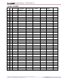
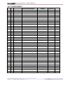
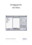
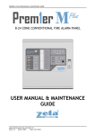
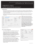
PREMIER EX8 EXTINGUISHING PANEL USER MANUAL COMBINED FIRE & EXTINGUISHING CONTROL PANEL COMPLIES WITH BS EN 12094 PART 1 & EN54 PARTS 2 & 4 USER MANUAL Approved Document No: GLT.MAN-132 Issue : 1.2 Author: NRPJ Date: 06/10/2010 Extinguishing Panel - USER MANUAL INDEX INDEX ....................................................................................................................................... 2 INTRODUCTION ...................................................................................................................... 3 INDICATIONS & CONTROLS ................................................................................................ 4 Indications .............................................................................................................................. 4 Controls .................................................................................................................................. 6 PANEL OPERATION ............................................................................................................... 7 Normal Operation ................................................................................................................... 7 Fire Alarm Condition (Peripheral Zones) .............................................................................. 7 What to do in the event of a fire. ........................................................................................ 7 Resetting from an alarm condition ..................................................................................... 7 First Stage Alarm ................................................................................................................... 8 Second Stage Alarm ............................................................................................................... 8 Hold / Abort a Second Stage Alarm ...................................................................................... 8 Manual Mode ......................................................................................................................... 8 Reset ....................................................................................................................................... 9 Faults ...................................................................................................................................... 9 DISABLEMENT ...................................................................................................................... 10 To Programme an Input or Output as Disabled.................................................................... 10 LOG BOOK ............................................................................................................................. 11 MAINTENANCE WORK ................................................................................................... 11 FALSE ALARMS ................................................................................................................ 12 ALL OTHER EVENTS ....................................................................................................... 13 Approved Document No: GLT.MAN-132 Issue : 1.2 Author: NRPJ Date: 06/10/2010 PAGE 2 Extinguishing Panel - USER MANUAL INTRODUCTION The Premier EX 8 is a combined 2 zone , 1 area extinguishing panel, and 4 zone conventional fire alarm panel. It has 2 zones dedicated to the extinguishing section. These are known as crossed or co-incidence zones. Both circuits will need to be triggered in order to activate the extinguishing circuit. This kind of operation also referred to as “double – knock” It has 4 zones for fire detection (referred to as peripheral zones, or fire zones). These will not trigger the extinguishing circuit. The Extinguishing section is designed to BSEN12094-1:2003. The fire alarm section is designed to EN54-2:1998 A1 + A2. The Power Supply section is designed to EN54-4:1998 A1 + A2 This design allows the same panel to protect an extinguishing area, and also monitor the rest of the site for a fire. The panel has an integral Manual Release call point fitted to the front of the panel. The panel has monitored inputs for field connections, such as manual release, emergency hold, etc. The panel has relay outputs for first & second stage alarms, fault & gas fired. The panel has remote inputs for Start/Stop Sounders, Silence & Reset, to allow the panel to be controlled remotely. The panel has Open collector repeat outputs for most panel status indications (eg 1 st stage alarm, 2nd stage alarm, Automatic mode, Manual mode etc) The panel has a connection for a serial repeater unit (4 wire) The Premier EX8 can be in any of the following conditions: Quiescent condition – ie System Normal Fire condition – ie a fire on one of the peripheral zones o The Premier EX8 will enter the fire condition within 1 second of a detector on a peripheral zone signalling an alarm. Fault condition Disabled condition Test condition Pre-activated condition o The Premier EX8 will enter the pre-activated condition (first stage alarm) within 1 second of a detector on one of the crossed zone signalling an alarm. Activated condition o The Premier EX8 will enter the activated (second stage alarm) condition within 1 second of the second crossed zone signalling an alarm. Released condition o The Premier EX8 will enter the released condition (bottle output activated) within 1 second of establishing the activated condition, OR after the delay configured in the bottle output timer. WARNING: Access to live components inside this fire alarm enclosure. The key to open the door to gain internal access should be held by authorised personnel only. Approved Document No: GLT.MAN-132 Issue : 1.2 Author: NRPJ Date: 06/10/2010 PAGE 3 Extinguishing Panel - USER MANUAL INDICATIONS & CONTROLS Indications Here is the fascia for the Premier EX8 panel. SUPPLY COMBINED FIRE & EXTINGUISHING CONTROL PANEL COMPLIES WITH BS EN 12094 PART 1:2003 CLASS A & EN54 PARTS 2 & 4 START/STOP 1st STAGE SOUNDERS SILENCE BUZZER FIRE PANEL EXTINGUISHING SYSTEM SC RO LL SC RO LL DISABLED by GLT Exports Ltd MADE IN THE UK Each function has its own indication LED. There are Alarm (Active), Fault, Test & Disablement LEDs for most panel inputs & outputs. Some of these indications are not applicable for certain functions (EG a fault on the 1st or 2nd stage relays). In such cases, the LEDs are not present on the matrix (See white outlines above) For most functions, more than one LED will light (eg zone 1 fire & COMMON ALARM) The second stage sounder is pulsed, and it`s sounder active LED will also pulse in time with the actual sounder output. The panel also has a 3 digit 7 segment display. This is used to display the countdown timers during a second stage alarm. Approved Document No: GLT.MAN-132 Issue : 1.2 Author: NRPJ Date: 06/10/2010 PAGE 4 Extinguishing Panel - USER MANUAL The Premier EX8 has the following LED indicators:LED COLOUR FUNCTION / MEANING POWER COMMON FIRE COMMON FAULT BATTERY FAULT CHARGER FAULT LOW BATTERY EARTH FAULT EXT.FAN DISABLE SYSTEM FAULT REMOTE FAULT REPEATER FAULT GEN S/C FAULT GREEN RED YELLOW YELLOW YELLOW YELLOW YELLOW YELLOW YELLOW YELLOW YELLOW YELLOW The panel is supplied with power, either battery, mains or both There is an alarm on the system. Check which zone caused the alarm There is a fault on the system. Another LED(s) will be lit to indicate the specific fault There is a problem with the batteries. Rectify or replace. The panel is not charging the batteries (usually mains fail or low mains) The batteries are below their final voltage & should be replaced Problem in system wiring. At least one cable is shorting to earth. The external equipment relay has been disabled The CPU has crashed, (Or CPU reset has been pressed & held) The panel has received a fault input from external equipment The panel has lost communication with the repeater panel Indicated that a line fault is caused by a short circuit EXTINGUISHANTRELEASED RELEASEIMMINENT HOLD/ABORT MANUALRELEASE ST 1 STAGEALARM ND 2 STAGEALARM LOWPRESSURE FLOODINGZONEFAULT MANUALMODE AUTOMATICMODE RED RED YELLOW RED RED RED YELLOW YELLOW YELLOW GREEN The bottle output has been activated & the gas released The panel has started the release timer and will activate bottle imminently An emergency hold OR emergency abort input has been activated. A manual release call point has been activated One of the crossed zones is in alarm Both of the crossed zones are in alarm A drop in bottle pressure has been detected There is a fault relating to the flooding zone1 (ie the extinguishing section of the panel) The panel is in manual only mode (ie will not be triggered by detectors) The panel is in automatic or manual mode GENERALDISABLEMENT GENERALTEST CONTROLSACTIVE YELLOW YELLOW YELLOW Lights when any section of the system is disabled Lights when any section of the panel is in test mode Lights when controls enabled keyswitch is on ZONE1-6FIRE ZONE1-6FAULT ZONE1-6TEST ZONE1-6DISABLED RED YELLOW YELLOW YELLOW Lights when one of the detection zones is in alarm Lights when one of the detection zones has a fault Lights when one of the detection zones is in test mode Lights when one of the detection zones is in disablement mode 1STSTAGESNDR ACTIVE 1STSTAGESNDRFAULT 1STSTAGESNDRTEST 1STSTAGESNDRDISABLED 2ND STAGESNDRACTIVE 2ND STAGESNDRFAULT 2ND STAGESNDRTEST 2ND STAGESNDRDISABLED BOTTLEOUTPUTACTIVE BOTTLEOUTPUTFAULT BOTTLEOUTPUTDISABLED 1STSTAGERELAYACTIVE 1STSTAGERELAY TEST 1STSTAGERELAYDISABLED 2ND STAGERELAY ACTIVE 2ND STAGERELAY TEST 2ND STAGERELAY DISABLED RED YELLOW YELLOW YELLOW RED YELLOW YELLOW YELLOW RED YELLOW YELLOW RED YELLOW YELLOW RED YELLOW YELLOW Lights when the first stage sounder is on Lights when the first stage sounder has a wiring fault Lights when the first stage sounder is in test mode Lights when the first stage sounder is disabled Lights when the second stage sounder is on Lights when the second stage sounder has a wiring fault Lights when the second stage sounder is in test mode Lights when the second stage sounder is disabled Lights when the bottle output is on Lights when the bottle output has a wiring fault Lights when the bottle output is disabled Lights when the first stage relay is on Lights when the first stage relay is in test mode Lights when the first stage relay is disabled Lights when the second stage relay is on Lights when the second stage relay is in test mode Lights when the second stage relay is disabled MAN.LRELEASEINPUTACTIVE MAN.RELEASEINPUTFAULT MAN.RELEASEINPUT DISABLED GASFIREDINPUTACTIVE GASFIREDINPUTFAULT EMERG.HOLDINPUTACTIVE EMERG.HOLDINPUTFAULT EMERG.ABORTINPUTACTIVE EMERG.ABORTINPUTFAULT AUTO/MANUALINPUTACTIVE AUTO/MANUALINPUTFAULT PRESS.SWITCHINPUTACTIVE PRESS.SWITCHINPUTFAULT BOTTLESCALESINPUTACTIVE BOTTLESCALESINPUTFAULT RED YELLOW YELLOW RED YELLOW YELLOW YELLOW YELLOW YELLOW YELLOW YELLOW YELLOW YELLOW YELLOW YELLOW A manual release call point connected to the remote input has been activated Fault in wiring to Manual release call point Manual release call point circuit is disabled The panel has received a signal from the cylinder to say the gas has been released. There is a wiring fault to the bottle`s sensor The emergency hold input has been activated Fault in wiring to Emergency hold switch The emergency abort input has been activated Fault in wiring to Emergency abort switch The panel has been set to manual mode by a remote input Fault in wiring to Auto / Manual switch The bottle`s pressure switch output has been activated Fault in wiring to bottle`s pressure switch The bottle`s scales switch has been activated Fault in wiring to bottle`s scales switch ACCESSLEVEL3 GASRELEASECOUNTER RELEASEDURATIONTIME RESETINHIBITTIME YELLOW YELLOW YELLOW YELLOW Access level 3 selected Gas release counter is being displayed on 3 digit display Release duration time is being displayed on 3 digit display Reset inhibit time is being displayed on 3 digit display Approved Document No: GLT.MAN-132 Issue : 1.2 Author: NRPJ Date: 06/10/2010 PAGE 5 Extinguishing Panel - USER MANUAL Controls The Premier EX8 has the following controls:LABEL st START/STOP 1 STAGE SOUNDER SILENCE BUZZER RESET FIRE PANEL RESET EXTINGUISHING SYSTEM LED TEST DISABLE DISABLE – SELECT DISABLE – CONFIRM TEST TEST – SELECT TEST – CONFIRM AUTO / MANUAL GAS RELEASE COUNTER RELEASE DURATION TIME RESET INHIBIT TIME 0-9 ENTER CANCEL TERMINATE DURATION TIMER USE Used to silence the sounders in an alarm, or to manually start the FIRST STAGE sounders to evacuate building Used to silence the panel`s internal buzzer in a fault or alarm condition. Used to reset the Fire detection section of the Control panel (Ie Zones 1 to 6) Used to Reset the extinguishing section of the Control panel. To check that all indicator LEDs are working. Use as part of the daily / weekly fire alarm inspection. Used to access Disablement mode Used to scroll to select which part of the system to disable Used to confirm disablement of the highlighted part of the system. Used to access test mode Used to scroll to select which part of the system to test Used to confirm test mode of the highlighted part of the system. Used to toggle between automatic & manual only mode Used to view or alter Gas Release Counter Used to view or alter Release Duration Time Counter Used to view or alter Reset Inhibit Time Counter To enter access code & timer values To confirm new timer setting To Save an edited time and exit from the timer set-up. Used to terminate the release duration timer (Bottle output Active). Internal button. Used during commissioning only. Note that the controls can only be used after the keyswitch has been turned to the CONTROLS ENABLED (ON) position. As the Premier EX8 is a combined Extinguishing & fire alarm control panel, it is possible that both the extinguishing section, and the fire alarm section are in alarm at the same time. If this occurs, the reset Fire Panel button can be used to reset the Zone alarms, leaving the extinguishing section active. After the pre-programmed Reset Inhibit delay, the reset Extinguishing System button can then be used to reset the extinguishing section. If the Extinguishing system has been through it`s release cycle, and the zones that triggered the release are still in alarm, the reset fire panel button must be pressed first to reset the zones in alarm, before the reset extinguishing system button can be pressed. Approved Document No: GLT.MAN-132 Issue : 1.2 Author: NRPJ Date: 06/10/2010 PAGE 6 Extinguishing Panel - USER MANUAL PANEL OPERATION Normal Operation With the “CONTROL” Key in the “OFF” position and under normal conditions the system will be silent and the green “POWER LED” illuminated. The system may either be in “Automatic” or “Manual” mode of operation. This will be evident by the illumination of either the “Automatic” or “Manual” LED. In Manual Mode, the bottle output will not be activated automatically. It must be started manually by pressing a manual release call point. Fire Alarm Condition (Peripheral Zones) The Premier EX8 signals an alarm by the following: Turn on the General Fire LED Turn on the Zonal Fire Indicator Turn on internal buzzer Start any sounders connected to the panel`s sounder circuits Activate the fire relay What to do in the event of a fire. 1. Follow the building evacuation procedure, and check that everyone has left the building safely. 2. The building fire officer or suitably trained responsible person should CAREFULLY enter the building, and locate the area of the alarm from the fire alarm panel. 3. Investigate to determine the cause of the alarm. Look for the detector in the zone in alarm that signalled the fire. The detector that signalled an alarm will have its RED ALARM LED on. 4. If a small fire is found, a suitably trained person could tackle this with a suitable fire extinguisher. 5. If a larger fire is found, leave the building immediately, and contact the fire brigade. 6. If no fire is found, make a note of the detector that signalled fire, and look for anything nearby that could be the cause of the activation, eg cooking, or use of a hot air gun etc. 7. Record findings in the fire alarm log book. Resetting from an alarm condition After the relevant action has been taken, the Premier EX8 fire alarm panel can be reset by the following:1 2 3 Press Start/Stop sounder button, This will silence the external sounders. Press Silence Fault Tone button. This will silence the panel`s internal buzzer. Press the Reset button. This will return the panel to it`s normal condition. If the panel goes straight back into alarm, then the cause of the alarm has not been cleared. This could be a detector still exposed to smoke, or a call point still in the active position. Press Start/Stop Sounder button, followed by silence buzzer button on the panel, then investigate for a call point, or detector that still has it`s RED ALARM LED on. Reset the call point, or clear the smoke. If the problem persists, contact an engineer. Approved Document No: GLT.MAN-132 Issue : 1.2 Author: NRPJ Date: 06/10/2010 PAGE 7 Extinguishing Panel - USER MANUAL First Stage Alarm On detection of a “FIRE” in either Zone 1 or Zone 2, the zone fire LED will be illuminated and the internal buzzer will be on. The first stage LED and first stage sounder will be on. The first stage relay output will be active. To silence the sounder, turn the keyswitch to ON position, and press silence button. The panel’s internal tone and fire LEDs will remain active until the cause of the alarm has been removed, and the panel has been reset A first stage alarm can be created manually by turning the keyswitch to the on position and pressing the 1st STAGE ALARM button. A first stage alarm can be silenced & reset when the panel is in automatic or manual mode. Second Stage Alarm As soon as a “FIRE” is detected in the second Zone, the second stage alarm is initiated. The second stage sounder will be pulsed on for 1 second, then off for 1 second. This will be repeated as the timer counts down. The two-zone alarm LEDs will be illuminated as well as first stage alarm, second stage alarm and Gas Imminent LEDs. The second stage cannot be silenced and after a delay period, (Set by the the installer) the extinguishing output will be initiated releasing the extinguishing agent, and the second stage sounder will now be on constantly. This will be followed by the “GAS FIRED” indication, indicating that the extinguishing agent has been released. Once the second stage alarm has been initiated, it is advisable to evacuate and Seal the protected area prior to the release of the extinguishing agent. Also, the operation of the Yellow “Manual Release” call point will initiate the second stage alarm. To do this, lift the flap and push the operating element. A second stage alarm can only be silenced & reset when the panel is in manual mode. Hold / Abort a Second Stage Alarm If the hold input is activated during a second stage alarm, the second stage sounder will now pulse on for 0.5 seconds, then be off for 2 seconds, and will repeat. The counter will be reset to it`s programmed value and the panel will restart it`s programmed countdown when the input is released. If an abort input is used, the panel will abort the gas release, and the panel will need to be reset. Manual Mode In this mode operation, Zone Fire and Fault alarms are still in operation, and first & second stage sounders will operate, but the bottle output to the extinguishing agent will not operate. Approved Document No: GLT.MAN-132 Issue : 1.2 Author: NRPJ Date: 06/10/2010 PAGE 8 Extinguishing Panel - USER MANUAL Reset To reset panel from an alarm condition, press Start/Stop Sounders, Silence Buzzer, then Reset. If the panel enters the second stage alarm (while in automatic mode), the panel cannot be reset until the reset inhibit timer has finished it`s countdown. The panel can NOT be reset from a fault condition. All faults are non latching, so when a fault clears from the panel it will be automatically cleared from the display. Faults The relevant LED will illuminate and the internal tone will sound. Pressing the “Silence buzzer” button, with the control key “ON”, will silence the tone. If there are any faults, call an Engineer. Approved Document No: GLT.MAN-132 Issue : 1.2 Author: NRPJ Date: 06/10/2010 PAGE 9 Extinguishing Panel - USER MANUAL DISABLEMENT The Premier EX8 allows any of the following to be disabled to aid commissioning and assist routine maintenance work: Crossed zones Peripheral Zones First stage sounders Second stage sounders & Bottle output (Disabled together) First Stage Relay Second Stage Relay External Equipment Relay When an zone is disabled, the panel will not respond to any fault or fire signals it receives from that input. When an output is disabled, the panel will not activate that output. This might be used if the system requires routine maintenance, and the customer needs the system to continue running, but doesn’t want spurious false alarms or fault signals. The panel will respond in the usual manner to any events in any non-disabled inputs. To Programme an Input or Output as Disabled Any number of inputs or outputs can be disabled, but it is good practice to only disable the minimum requirement at a time. Insert and turn control key to enabled position; Press DISABLE button and the GENERAL DISABLEMENT LED will come on (flashing fast, 4 flashes then off, repeated); Press SELECT button. The GENERAL DISABLEMENT LED will light steady, and the Crossed Zone 1 Disabled LED will flash 4 quick flashes & off. The panel is now in SELECT DISABLEMENT MODE. The select button is used to highlight (flash) the section that needs to be disabled. Press select button until the correct LED is flashing, then press confirm. The LED will now flash 4 quick flashes & on, to indicate that this section is disabled. If more than one section needs to be disabled, then press SELECT button again until the required zone is selected. (The previously disabled section will now have its disabled LED lit steady.) If the panel needs to be taken out of SELECT DISABLEMENT MODE (eg to silence a fault on another part of the system), turn the keyswitch off, then back on again. Once all the work has been done the zones need to be enabled again. If the panel is not in SELECT DISABLEMENT MODE, turn the keyswitch to controls enabled, press DISABLE button. Press the scroll button until the disabled section has been selected. Press CONFIRM button to reenable. Scroll to any other disabled section and enable in the same way. When all sections are enabled again, turn the keyswitch to off to return the system to normal. NOTE: During a Disabled condition, sections of the fire alarm system will be inoperative. Extra caution should be used in the disabled part of the premises. Approved Document No: GLT.MAN-132 Issue : 1.2 Author: NRPJ Date: 06/10/2010 PAGE 10 Extinguishing Panel - USER MANUAL LOG BOOK MAINTENANCE WORK DATE TIME ZONE / LOCATION REASON FOR WORK Approved Document No: GLT.MAN-132 Issue : 1.2 Author: NRPJ Date: 06/10/2010 WORK CARRIED OUT ADDITIONAL WORK REQUIRED PAGE 11 SIGNED Extinguishing Panel - USER MANUAL FALSE ALARMS DATE TIME ZONE / LOCATION CAUSE (IF KNOWN) OR ACTIVITIES IN ALARM AREA Approved Document No: GLT.MAN-132 Issue : 1.2 Author: NRPJ Date: 06/10/2010 MAINTENANCE VISIT NEEDED (YES/NO) MAINTENANCE FINDINGS CATEGORY OF FURTHER FALSE ALARM ACTION REQUIRED PAGE 12 SIGNED Extinguishing Panel - USER MANUAL ALL OTHER EVENTS DATE TIME ZONE / LOCATION DETAILS OF EVENT (INCLUDING CAUSE IF KNOWN) Approved Document No: GLT.MAN-132 Issue : 1.2 Author: NRPJ Date: 06/10/2010 ACTION REQUIRED DATE COMPLETED PAGE 13 INITIALS