Download 2 - Idec

Transcript
B-1698(0)
External Device Setup Manual
SAFETY PRECAUTATIONS
Confirm that the delivered product is what you have ordered. Read this manual to make sure of correct operation.
SAFETY PRECAUTATIONS
• Be certain to read the INSTRUCTION SHEET and the WindO/I-NV4 User's manual carefully before performing
installation, wiring, or maintenance work, or operating the HG2G-5T.
• The HG2G-5T has been manufactured with careful regard to quality. However, if you intend to use this product in
applications where failure of this equipment may result in damage to property or injury, ensure that it used in
conjunction with appropriate fail-safe backup equipment.
• In this manual, safety precautions are categorized in order of importance to Warning and Caution:
Warning notices are used to emphasize that improper operation may cause severe
personal injury or death.
Caution notices are used where inattention might cause personal injury or damage to
equipment.
• The HG2G-5T is not intended to be used for applications which require high reliability and safety, such as medical
equipment, nuclear equipment, railways, aircraft, and vehicles. The HG2G-5T cannot be used for these applications.
For other applications which require high reliability in function and precision, provide a failsafe design and redundant
design for the entire system including the HG2G-5T.
• Turn off the power to the HG2G-5T before installation, removal, wiring, maintenance, and inspection of the HG2G-5T.
Failure to turn power off may cause electrical shock or fire hazard.
• Special expertise is required to install, wire, configure, and operate the HG2G-5T. People without such expertise must
not use the HG2G-5T.
• The HG2G-5T uses an LCD (liquid crystal display) as a display device. The liquid inside the LCD is harmful to the skin.
If the LCD is broken and the liquid attaches to your skin or clothes, wash the liquid off using soap, and consult a
doctor immediately.
• Emergency and interlocking circuits must be configured outside of the HG2G-5T.
• Do not use the HG2G-5T's internal touch switches for an emergency circuit. If the HG2G-5T failed, the external
equipment connected to the HG2G-5T will no longer be protected, and serious injury to operators and equipment
damage may be caused.
Preface-1
WindO/I-NV4 External Device Setup Manual
SAFETY PRECAUTATIONS
• Prevent the HG2G-5T from falling while moving or transporting, otherwise damage or malfunction of the HG2G-5T will
result.
• Use the product within the environmental limits given in the catalog and manual. Use of the product in hightemperature or high-humidity environments, or in locations where it is exposed to condensation, corrosive gas or large
shock loads can create the risk of electrocution and fire.
• The HG2G-5T is designed for use in pollution degree 2. Use the HG2G-5T in environments of pollution degree 2.
(based on the IEC60664-1 rating)
• Install the HG2G-5T according to the instructions. Improper installation will result in falling, failure, electrical shock,
fire hazard, or malfunction of the HG2G-5T.
• Prevent metal fragments or wire chips from dropping inside the HG2G-5T housing. Ingress of such fragments and
chips may cause fire hazard, damage, and malfunction.
• Use a power supply of the rated value. Using a wrong power supply may cause fire hazard.
• The HG2G-5T uses “PS2 of EN61131” as DC power supply. (based on the IEC/EN61131 rating)
• Use wire of a proper size to meet the voltage and current requirements.
• When exporting the HG2G-5T to Europe, use an EN60127 (IEC60127) approved fuse on the power line outside the
HG2G-5T.
• When exporting the HG2G-5T to Europe, use an EU-approved circuit protector.
• Make sure of safety before starting and stopping the HG2G-5T. Incorrect operation of the HG2G-5T may cause
mechanical damage or accidents.
• Use the HG2G-5T in a local area network if you download, upload or monitor the project data via the Ethernet port.
• The touch panel of the HG2G-5T is made of glass, and will break if exposed to excessive shock. Take due care when
handling it.
• When more than one button is pressed at the same time, due to the detection characteristics of an analog type touch
panel, only the gravity center of the pressed area is sensed and the unit assumes that only one button is pressed.
Thus, don't operate the MICRO/I by pressing more than one button simultaneously.
• The screen becomes blank when the backlight is burnt out; however, the touch panel remains enabled. Incorrect
touch panel operation will occur when operating the touch panel when the backlight appears to be turned off but is
actually burnt out. Note that this erroneous operation may result in damage.
• Do not push hard or scratch the touch panel and protection sheet with a hard object such as a tool, because they are
damaged easily.
• At temperatures over the rated operating temperature, the clock accuracy is affected. Adjust the clock before use.
• For applications which require clock accuracy, adjust the clock periodically.
• Do not install the HG2G-5T in areas subjected to strong ultraviolet rays, since ultraviolet rays may impair the quality of
the LCD.
• Do not attempt to disassemble, repair or modify the HG2G-5T. This can create the risk of fire or electrocution.
• When disposing of the HG2G-5T, do so as an industrial waste.
• Do not switch off the power or pull out the USB flash drive while it is being accessed, as this may result in destruction
of the stored data. If the data on the USB flash drive is corrupted, format the USB flash drive.
WindO/I-NV4 External Device Setup Manual
Preface-2
Revision history
Revision history
August 2015:
First Edition
Caution
• The contents of this manual and the WindO/I-NV4 application are copyright, and all rights are reserved by IDEC
Corporation. Unauthorized reproduction is prohibited.
• The contents of this manual and the WindO/I-NV4 application are subject to change without notice.
• IDEC Corporation accepts no responsibility for circumstances arising from the use of this manual or the WindO/INV4 application.
• Please contact your vendor or IDEC Corporation with any problems regarding the operation of this product.
Trademarks
WindO/I and MICRO/I are registered trademarks of IDEC CORPORATION in JAPAN. Microsoft, Windows, Windows
XP, Windows Vista, Windows 7, and Windows 8 are either registered trademarks or trademarks of Microsoft
Corporation in the United States and/or other countries. Adobe is a trademark of Adobe Systems Incorporated.
All other company names and product names used in this manual or the WindO/I-NV4 application are trademarks
of their respective owners.
This product adopts the font of Ryobi.
Preface-3
WindO/I-NV4 External Device Setup Manual
Symbols Used in this Document
This manual uses the following symbols to facilitate description.
Symbols
......
Information that requires special attention. Failure to operate the product in accordance
with the information provided can lead to serious injury or damage.
......
Information relating to requests or material to reference in the use of a function.
......
Useful information relating to a function.

......
Indicates the chapter and page of related reference information.
OK
......
Screen buttons are indicated by bold text or by using the actual graphic icon.
SHIFT, A
......
Keyboard keys are indicated by the keyboard inscription in capital letters or enclosed in
square brackets.
......
Controls are indicated by bold text.
WindO/I-NV4 External Device Setup Manual
Preface-4
Abbreviations, Generic Terms, and Terminology Used in this Manual
Item
Description
HG4G
The name is short for MICRO/I HG4G-CJT22*F-B.
HG3G
The name is short for MICRO/I HG3G-*JT22*F-*.
HG2G-S
The name is short for MICRO/I HG2G-S*2**F-*.
HG2G-5S
The name is short for MICRO/I HG2G-5ST22*F-*.
HG2G-5F
The name is short for MICRO/I HG2G-5FT22TF-*.
HG2G-5T
The name is short for MICRO/I HG2G-5T*22TF-*.
HG4G/3G
The format used to refer to HG4G and HG3G.
HG2G-5F/-5T/-5S/-S
The format used to refer to HG2G-5F, HG2G-5T, HG2G-5S and HG2G-S.
MICRO/I
Generic term for programmable display device.
External device
Generic term used to refer to a PLC or micro computer that is connected to and
communicates with the MICRO/I or Touch.
Device Address
Memory that is capable of storing values in unit of bits or words loaded on the
MICRO/I or Touch and external device.
System Area
Device area that is pre-allocated for exchanging screen management, error
information, and clock data between the MICRO/I or Touch and external device.
Device Link Communication
A communication method that performs communication with the external device
according to the setting of the screen and without a program.
DM Link Communication
A communication method that reads to or writes from the MICRO/I or Touch
device from a computer or microcomputer board.
User Communication
A communication method which performs communication with external devices
such as barcode readers and inverters.
External Device Communication
Generic term used to refer to Device Link Communication and DM Link
Communication.
Sub Host Communication
A communication method that performs communication with external device
according to the set device address list and without a program.
O/I Link
A connection format that enables connections of up to 16 units of MICRO/I with
high-speed communication of 115200bps.
O/I Link Master
The MICRO/I unit that is directly connected to external device on the O/I Link
network.
O/I Link Slave
The MICRO/I units that are not directly connected to external device on the O/I Link
network.
WindO/I-NV4
Integrated configuration software application for creating projects of the MICRO/I.
Project
Data including image data required for operating the MICRO/I, which is created with
WindO/I-NV4.
Manager
WindO/I-NV4 provides tools to manage pictures, text and script etc. With the
Managers, you can create and manage them in your project.
Setup
Generic term used to refer to the common settings in the project.
Project Settings
Basic settings of operation in the Setup settings.
Alarm Log
A function where the MICRO/I collects log data of alarms.
Data Log
A function where the MICRO/I collects value of device addresses.
Script
A script is an executable list of commands created by a simple programming
language.
Text Group
A group of 32 texts maximum that is in order to dynamically switch the character
displayed on the MICRO/I according to the value of the device address.
Windows Font
Text fonts that can be displayed on the Windows OS on which the WindO/I-NV4 is
running.
Stroke Font
A glyph's outline is defined by the vertices of individual strokes and stroke's profile.
Scalable fonts scale easily without jagged edges.
Under font settings, “Stroke” is a stroke-based font.
Maintenance Communication
Communications between the WindO/I-NV4 and MICRO/I using a dedicated protocol.
Device Monitor
A special Popup Screen on the MICRO/I on which value of the device address can be
displayed or changed.
Preface-5
WindO/I-NV4 External Device Setup Manual
Abbreviations, Generic Terms, and Terminology Used in this Manual
Item
Description
Pass-Through
A function that enables maintenance of the external device via the MICRO/I.
System Screen
Pre-allocated screen dedicated for performing initial setting of the MICRO/I,
self-diagnosis, and clearing the log data etc.
External Memory Device
The generic term for an SD memory card and a USB flash drive.
NV Metafile
A graphic data file that integrates drawings created on the WindO/I-NV4 edit screen.
Window
Screens that are loaded on to the Base Screen, including Popup Screen and Device
Monitor.
Internal Device
The generic term for internal device addressing on the MICRO/I such as internal
relays, registers, etc.
Keep Device
The generic term for internal device not initialized at the start of operation. Even
after the power is turned off, the values are retained by the battery.
Drawings
Define as as non functional content (i.e. shape, picture, text).
Parts
Define as functional content (i.e. button, pilot lamp, commands, etc.)
Object
Define as combination of Drawings and Parts placed on WindO/I-NV4 edit screen.
Touch Switch
A part that operates a function by pressing parts that have been placed on the
screen.
Standard Keypad
Keypad that is displayed when operating Numerical and Character Input parts when
Standard is selected under Type in the Keypad menu for Numerical and Character
Input parts.
WindO/I-NV4 External Device Setup Manual
Preface-6
Contents
SAFETY PRECAUTATIONS ................................................................... Preface-1
Revision history ................................................................................. Preface-3
Caution ............................................................................................ Preface-3
Trademarks....................................................................................... Preface-3
Symbols Used in this Document........................................................... Preface-4
Abbreviations, Generic Terms, and Terminology Used in this Manual ....... Preface-5
Chapter 1
1
Overview ....................................................................................................1-1
2
Settings ......................................................................................................1-2
3
Important Points Regarding Wiring ................................................................1-4
Chapter 2
1
2
3
4
5
Preface-7
Device Link Communication
Connection to External Devices
IDEC ..........................................................................................................2-1
1.1
Connection Table ....................................................................................... 2-1
1.2
System Configuration ................................................................................. 2-4
1.3
Connection Diagram................................................................................. 2-10
1.4
Environment Settings ............................................................................... 2-12
1.5
Usable Device Addresses .......................................................................... 2-13
Mitsubishi Electric ...................................................................................... 2-14
2.1
Connection Table ..................................................................................... 2-14
2.2
System Configuration ............................................................................... 2-20
2.3
Connection Diagram................................................................................. 2-26
2.4
Environment Settings ............................................................................... 2-30
2.5
Usable Device Addresses .......................................................................... 2-35
OMRON .................................................................................................... 2-49
3.1
Connection Table ..................................................................................... 2-49
3.2
System Configuration ............................................................................... 2-52
3.3
Connection Diagram................................................................................. 2-58
3.4
Environment Settings ............................................................................... 2-61
3.5
Usable Device Addresses .......................................................................... 2-65
Allen-Bradley ............................................................................................ 2-69
4.1
Connection Table ..................................................................................... 2-69
4.2
System Configuration ............................................................................... 2-71
4.3
Connection Diagram................................................................................. 2-73
4.4
Environment Settings ............................................................................... 2-76
4.5
Usable Device Addresses .......................................................................... 2-79
4.6
How to set Device Address for ControlLogix and CompactLogix series ............ 2-91
SIEMENS .................................................................................................. 2-93
5.1
Connection Table ..................................................................................... 2-93
5.2
System Configuration ............................................................................... 2-94
5.3
Connection Diagram................................................................................. 2-95
5.4
Environment Settings ............................................................................... 2-97
WindO/I-NV4 External Device Setup Manual
5.5
6
7
8
9
10
11
12
13
Usable Device Addresses .......................................................................... 2-99
KEYENCE.................................................................................................2-103
6.1
Connection Table ................................................................................... 2-103
6.2
System Configuration ............................................................................. 2-104
6.3
Connection Diagram............................................................................... 2-106
6.4
Environment Settings ............................................................................. 2-108
6.5
Usable Device Addresses ........................................................................ 2-110
Hitachi ....................................................................................................2-113
7.1
Connection Table ................................................................................... 2-113
7.2
System Configuration ............................................................................. 2-114
7.3
Connection Diagram............................................................................... 2-116
7.4
Environment Settings ............................................................................. 2-117
7.5
Usable Device Addresses ........................................................................ 2-118
JTEKT (Toyoda) .......................................................................................2-119
8.1
Connection Table ................................................................................... 2-119
8.2
System Configuration ............................................................................. 2-119
8.3
Connection Diagram............................................................................... 2-120
8.4
Environment Settings ............................................................................. 2-121
8.5
Usable Device Addresses ........................................................................ 2-122
TOSHIBA MACHINE ..................................................................................2-125
9.1
Connection Table ................................................................................... 2-125
9.2
System Configuration ............................................................................. 2-125
9.3
Connection Diagram............................................................................... 2-126
9.4
Environment Settings ............................................................................. 2-127
9.5
Usable Device Addresses ........................................................................ 2-127
GE Fanuc Automation ...............................................................................2-128
10.1
Connection Table ................................................................................... 2-128
10.2
System Configuration ............................................................................. 2-129
10.3
Connection Diagram............................................................................... 2-130
10.4
Environment Settings ............................................................................. 2-132
10.5
Usable Device Addresses ........................................................................ 2-133
Panasonic................................................................................................2-134
11.1
Connection Table ................................................................................... 2-134
11.2
System Configuration ............................................................................. 2-135
11.3
Connection Diagram............................................................................... 2-137
11.4
Environment Settings ............................................................................. 2-140
11.5
Usable Device Addresses ........................................................................ 2-142
YASKAWA Electric ....................................................................................2-143
12.1
Connection Table ................................................................................... 2-143
12.2
System Configuration ............................................................................. 2-144
12.3
Connection Diagram............................................................................... 2-145
12.4
Environment Settings ............................................................................. 2-147
12.5
Usable Device Addresses ........................................................................ 2-149
KOYO ELECTRONICS INDUSTRIES..............................................................2-150
13.1
Connection Table ................................................................................... 2-150
13.2
System Configuration ............................................................................. 2-151
13.3
Connection Diagram............................................................................... 2-153
13.4
Environment Settings ............................................................................. 2-154
13.5
Usable Device Addresses ........................................................................ 2-156
WindO/I-NV4 External Device Setup Manual
Preface-8
14
15
16
17
18
19
20
21
Preface-9
FANUC ................................................................................................... 2-159
14.1
Connection Table ................................................................................... 2-159
14.2
System Configuration ............................................................................. 2-159
14.3
Connection Diagram............................................................................... 2-160
14.4
Environment Settings ............................................................................. 2-161
14.5
Usable Device Addresses ........................................................................ 2-162
Yokogawa Electric ................................................................................... 2-163
15.1
Connection Table ................................................................................... 2-163
15.2
System Configuration ............................................................................. 2-164
15.3
Connection Diagram............................................................................... 2-165
15.4
Environment Settings ............................................................................. 2-166
15.5
Usable Device Addresses ........................................................................ 2-167
Fuji Electric............................................................................................. 2-169
16.1
Connection Table ................................................................................... 2-169
16.2
System Configuration ............................................................................. 2-171
16.3
Connection Diagram............................................................................... 2-174
16.4
Environment Settings ............................................................................. 2-177
16.5
Usable Device Addresses ........................................................................ 2-181
Toshiba .................................................................................................. 2-184
17.1
Connection Table ................................................................................... 2-184
17.2
System Configuration ............................................................................. 2-185
17.3
Connection Diagram............................................................................... 2-187
17.4
Environment Settings ............................................................................. 2-190
17.5
Usable Device Addresses ........................................................................ 2-191
17.6
The mapping table of devices between PROSEC T Series and V Series ......... 2-192
LSIS ....................................................................................................... 2-193
18.1
Connection Table ................................................................................... 2-193
18.2
System Configuration ............................................................................. 2-194
18.3
Connection Diagram............................................................................... 2-195
18.4
Environment Settings ............................................................................. 2-197
18.5
Usable Device Addresses ........................................................................ 2-198
Vigor Electric .......................................................................................... 2-199
19.1
Connection Table ................................................................................... 2-199
19.2
System Configuration ............................................................................. 2-200
19.3
Connection Diagram............................................................................... 2-201
19.4
Environment Settings ............................................................................. 2-203
19.5
Usable Device Addresses ........................................................................ 2-204
Emerson Electric...................................................................................... 2-205
20.1
Connection Table ................................................................................... 2-205
20.2
System Configuration ............................................................................. 2-205
20.3
Connection Diagram............................................................................... 2-206
20.4
Environment Settings ............................................................................. 2-206
20.5
Usable Device Addresses ........................................................................ 2-207
Hitachi Industrial Equipment Systems ........................................................ 2-211
21.1
Connection Table ................................................................................... 2-211
21.2
System Configuration ............................................................................. 2-212
21.3
Environment Settings ............................................................................. 2-213
21.4
Usable Device Addresses ........................................................................ 2-214
WindO/I-NV4 External Device Setup Manual
22
Chapter 3
INVERTER ...............................................................................................2-215
22.1
Connection Table ................................................................................... 2-215
22.2
System Configuration ............................................................................. 2-215
22.3
Connection Diagram............................................................................... 2-215
22.4
Environment Settings ............................................................................. 2-216
22.5
Usable Device Addresses ........................................................................ 2-217
O/I Link Communication
1
Outline....................................................................................................... 3-1
2
Settings ..................................................................................................... 3-3
3
Communication Service ................................................................................ 3-4
1.1
4
5
3.1
O/I Link slave Registration Setting Register (LSD102 in the O/I Link master) .... 3-4
3.2
O/I Link slave Online Data Register (LSD104 in the O/I Link master) ............... 3-4
3.3
O/I Link Polling Period Register (LSD101 in the O/I Link slaves) ...................... 3-4
3.4
O/I Link slave Error information Register (LSD106 in the O/I Link master) ....... 3-4
Communication Status Confirmation .............................................................. 3-5
4.1
O/I Link Master Error Processing ................................................................. 3-5
4.2
O/I Link Slave Error Processing ................................................................... 3-5
4.3
Status of a Slave in the O/I Link .................................................................. 3-6
4.4
Slave changes status from Online to Offline in the O/I Link ............................ 3-6
Important Notes ......................................................................................... 3-7
5.1
6
1
3
4
5
6
Overview.................................................................................................... 4-1
Communication Methods ............................................................................ 4-1
System Configuration .................................................................................. 4-3
2.1
DM Link (1:1) Communication ..................................................................... 4-3
2.2
DM Link (1:N) Communication..................................................................... 4-3
Wiring........................................................................................................ 4-4
3.1
RS232C .................................................................................................... 4-4
3.2
RS422/485 ................................................................................................ 4-5
Communication Specifications ....................................................................... 4-6
4.1
Communication Method .............................................................................. 4-6
4.2
Communication Conditions.......................................................................... 4-6
4.3
Flow control .............................................................................................. 4-6
Data Memory (DM) Allocation ....................................................................... 4-7
5.1
System Area ............................................................................................. 4-7
5.2
Event transmission control area................................................................... 4-7
Settings ..................................................................................................... 4-8
6.1
7
Conditions ................................................................................................ 3-8
DM Link Communication
1.1
2
Communication Traffic Volume of the O/I Link Network .................................. 3-7
Result on the Performance Evaluation of the MICRO/I ..................................... 3-8
6.1
Chapter 4
Wiring Diagram ......................................................................................... 3-2
DM Link (1:1) Communication, DM Link (1:N) Communication ........................ 4-8
DM Link (1:1) Communication Format.......................................................... 4-10
7.1
Read ...................................................................................................... 4-10
WindO/I-NV4 External Device Setup Manual
Preface-10
8
7.2
Write ..................................................................................................... 4-13
7.3
Transmission Control ................................................................................ 4-15
7.4
Clear ...................................................................................................... 4-17
7.5
Event Transmission .................................................................................. 4-18
DM Link (1:N) Communication Format.......................................................... 4-20
8.1
Read ...................................................................................................... 4-20
8.2
Write ..................................................................................................... 4-22
8.3
Clear ...................................................................................................... 4-24
8.4
Station Number ....................................................................................... 4-24
9
BCC Calculation ......................................................................................... 4-25
10
Error Codes .............................................................................................. 4-26
9.1
10.1
Chapter 5
1
2
3
4
5
6
Preface-11
BCC Calculation Example (for DM Link (1:N) Communication) ....................... 4-25
Response Time ........................................................................................ 4-26
Modbus
Connection Table.........................................................................................5-1
1.1
Compatible Protocols ................................................................................. 5-1
1.2
Compatible Table ....................................................................................... 5-2
System Configuration ...................................................................................5-3
2.1
Modbus RTU Master ................................................................................... 5-3
2.2
Modbus ASCII Master ................................................................................. 5-3
2.3
Modbus TCP Client..................................................................................... 5-3
2.4
Modbus TCP Server.................................................................................. 5-3
2.5
Modbus RTU Slave ..................................................................................... 5-4
2.6
Twido ....................................................................................................... 5-4
2.7
Momentum (MODUBS TCP Client) ................................................................ 5-7
Connection Diagram.....................................................................................5-9
3.1
Connection Diagram 1: TWDNAC232D.......................................................... 5-9
3.2
Connection Diagram 2: TWDNAC485D.......................................................... 5-9
3.3
Connection Diagram 3: TWDNAC485T .......................................................... 5-9
Environment Settings ................................................................................. 5-10
4.1
Twido ..................................................................................................... 5-10
4.2
Momentum (Modbus TCP Client) ............................................................... 5-10
Usable Device Addresses ............................................................................ 5-11
5.1
Modbus RTU Master, Modbus ASCII Master, Modbus TCP Client ..................... 5-11
5.2
Twido (Modbus RTU Master) ..................................................................... 5-11
5.3
Momentum (Modbus TCP Client) ............................................................... 5-11
Modbus TCP Server/Modbus RTU Slave Function ........................................... 5-12
6.1
Overview of the Modbus TCP Server, Modbus RTU Slave Function ................. 5-12
6.2
Modbus TCP Server function system configuration ....................................... 5-13
6.3
Modbus RTU Slave function system configuration ........................................ 5-13
6.4
Device Addresses .................................................................................... 5-14
6.5
Settings.................................................................................................. 5-15
6.6
Modbus TCP Server Function Communication Format ................................... 5-16
6.7
Modbus RTU Slave Function Communication Format .................................... 5-17
6.8
Modbus TCP/Modbus RTU shared protocol format........................................ 5-18
WindO/I-NV4 External Device Setup Manual
Chapter 6
1
Communication with Multiple External Devices
About 1:N Communication (Multi-drop) .......................................................... 6-1
1.1
Outline ..................................................................................................... 6-1
2
Communication Drivers Supporting 1:N Communication ................................... 6-2
3
Settings of the 1:N Communication ............................................................... 6-3
4
3.1
External Device Address Settings ................................................................. 6-3
3.2
Connection Diagram................................................................................... 6-6
1:N Communication Operation ...................................................................... 6-7
4.1
1:N Communication Operation..................................................................... 6-7
5
Using Multiple Communication Drivers ........................................................... 6-8
6
Restrictions ................................................................................................ 6-9
Chapter 7
1
Communication Cables
Communication Cables ................................................................................. 7-1
1.1
External devices/PLC connection cable: FC2A-KP1C, HG9Z-XC275 .................... 7-1
Index
WindO/I-NV4 External Device Setup Manual
Preface-12
Preface-13
WindO/I-NV4 External Device Setup Manual
Chapter 1
1
Device Link Communication
Overview
Device Link Communication refers to the communication protocol used for communication with the MICRO/I, via
Device Link Communicationn
MICRO/I
External device
Numerical Display
Reference Device Address: D0
Read
D0:
1234
1234
0
Bit Button
Destination Device Address: M0
Write
1
M0:
For details regarding the Command Method Communication, refer to Chapter 2 “Chapter 2 Connection to
External Devices” on page 2-1.
● Connection Types
There are two basic types of connections. 1:1 Communication, where an external device is connected to a
MICRO/I; and 1:N Communication, where multiple external devices are connected to a MICRO/I.
■ 1:1 Communication
The MICRO/I is connected to a single external device.
MICRO/I
Device Link Communication
External device
Read
Write
■ 1:N Communication
The MICRO/I is connected to multiple external devices.
MICRO/I
Device Link Communication
External device
Read
Write
Station No.1
Read
Write
Station No.2
Read
Write
Station No.3
*1 Unit names vary based on the manufacturer of the external device.
WindO/I-NV4 External Device Setup Manual
1-1
Device Link Communication
the CPU Unit*1 or PLC Link Unit*1 Programming Port of the external device connected to the MICRO/I.
The MICRO/I continuously reads the value of device of external device addresses on the currently displayed
screen, and external devices (such as relays and registers) on the screens are updated with the latest data at all
times.
When a button is pressed or a command is executed in the MICRO/I screen, the value is written to the external
device address.
1
2 Settings
2
Settings
You need to setup MICRO/I using WindO/I-NV4 in order for it to be able to communicate with the external devices.
Device Link Communication setting is set on the Project Settings dialog box displayed by clicking Project under
System Setup on the Configuration tab in WindO/I-NV4. For detail refer to WindO/I-NV4 User’s Manual. Match
the settings for the items in the following table to those of the external devices that you will be using.
Project Settings dialog box
Tab Name
System
Setting Name
Description
Start Time (sec)
This is the time delay until the MICRO/I sends a communication
command after the power is turned on. Set this option if the external
device is turned on after the MICRO/I, or some time is required until
the communication port of external devices can be used.
Use System Area
When Use System Area is selected, set the device address for
System Area.
Use System Areas 3, 4
Watch Dog
Device Address
When Watch Dog is selected, set the Device Address and the
Time for the write interval.
Time (sec)
Communication Interface Interface
Configuration
Select the interface used for the Device Link Communication.
Function
Select the Function to be used. The details of External Device
Communication 1 to the External Device Communication 4
are configured on the Communication Driver tab.
For details about O/Link Communication, refer to Chapter 3 “O/I Link
Communication” on page 3-1.
Baud Rate
The settings vary based on the external device used. Refer to
Chapter 2 “Connection to External Devices” on page 2-1.
Data Bits
Stop Bits
Parity
Flow Control
Serial Interface
Communication Driver
Manufacturer
Select the manufacturer and the communication driver from the list
of compatible External Devices given in Chapter 2 “Connection to
Communication Driver
External Devices” on page 2-1 that corresponds to the one you will
Connection
be using.
Transmission Wait
(x10 msec)
The settings vary based on the external device used. For detail refer
to Chapter 2 “Connection to External Devices” on page 2-1. If there
is no setting given for the transmission wait, set it to 0.
Time Out (x100 msec) This is the time that the MICRO/I will wait for a reply from the
External Device after it sends a communication command. When this
time elapses, the MICRO/I will send the command again.
(Default: 20)
Give careful consideration to the value that you will use before
changing this setting.
1-2
Retry Cycles
If communication errors occur despite trying the number set here,
an error is displayed on the screen and the error information is set in
the system area. (Default: 5)
(Other setting)
The settings vary based on the external device used. For detail refer
to Chapter 2 “Connection to External Devices” on page 2-1 for your
External Device.
WindO/I-NV4 External Device Setup Manual
2 Settings
Tab Name
Communication Driver
Network
Setting Name
Description
This number is used to distinguish an external device when set to a
device address.
IP Address
This option is IP address of each external devices.
Port Number
This option is Port Number of each external devices.
(Other setting)
These items vary based on the Communication Driver. You can see
some items if the selected Communication Driver has any setting
items. Refer to each manual for the external device.
WindO/I-NV4 External Device Setup Manual
1-3
1
Device Link Communication
Station Number
3 Important Points Regarding Wiring
3
Important Points Regarding Wiring
Take note of the following points when connecting an External Device to the MICRO/I.
• Depending on the environment, connect a shield wire to the FG terminal on either the External Device side or the
MICRO/I side.
• When using the RS422/485 interface of Serial Interface (SERIAL1), use a twisted-pair cable so that the + and signals are paired.
• When using RS422/485 interface, setting the Terminating Resistor Selector Switch ON inserts a 100-Ohm. Use it
if necessary. Refer to the setting of the Terminating Resistor Selector Switch as below.
HG2G-5T
Terminating Resistor Selector Switch
1-4
Serial Interface (SERIAL1)
WindO/I-NV4 External Device Setup Manual
Chapter 2
1
Connection to External Devices
IDEC
Selecting OpenNet,MICROSmart,SmartAXIS Pro/Lite(RS232C/485) as the Communication Driver allows
your to use the 1:N Communication function and Pass-through function. However, SmartAXIS Pro/Lite does not
support the Pass-through function. Selecting OpenNet,MICROSmart,SmartAXIS Pro/Lite(Ethernet) as the
Communication Driver allows you to use 1:N Communication function only.
• 1:N Communication function (Chapter 6 “Communication with Multiple External Devices” on page 6-1)
1.1 Connection Table
WindO/I-NV4 Settings
CPU unit
Link unit
Interface
Flow
Control
Communication Driver
OpenNet Controller
FC3A-CP2
Not required
(connects to CPU unit)
RS232C
Connection Diagram 1 (Page 2-10)
ER
RS422/485 2-wire
Connection Diagram 2 (Page 2-10)
None
Web Server Unit
(FC4A-SX5ES1E)
Ethernet
Not required
(connects to CPU unit)
RS232C
Connection Diagram 3 (Page 2-11)
OpenNet,MICROSmart,
SmartAXIS Pro/Lite(RS232C/485)
-
OpenNet,MICROSmart,
SmartAXIS Pro/Lite(Ethernet)
None
OpenNet,MICROSmart,
SmartAXIS Pro/Lite(RS232C/485)
-
OpenNet,MICROSmart,
SmartAXIS Pro/Lite(Ethernet)
None
OpenNet,MICROSmart,
SmartAXIS Pro/Lite(RS232C/485)
MICROSmart
FC4A-C10R2
RS232C
Connection Diagram 1 (Page 2-10)
FC4A-C16R2
FC4A-C24R2
Web Server Unit
(FC4A-SX5ES1E)
Ethernet
Not required
(connects to CPU unit)
RS232C
Connection Diagram 3 (Page 2-11)
RS232C
Connection Diagram 1 (Page 2-10)
FC4A-D20K3
FC4A-D20S3
FC4A-D20RK1
FC4A-D20RS1
FC4A-D40K3
FC4A-D40S3
FC4A-PC1
RS232C
Connection Diagram 1 (Page 2-10)
ER
FC4A-PC3
RS422/485 2-wire
Connection Diagram 2 (Page 2-10)
None
Web Server Unit
(FC4A-SX5ES1E)
Ethernet
Not required
(connects to CPU unit)
RS232C
Connection Diagram 3 (Page 2-11)
-
OpenNet,MICROSmart,
SmartAXIS Pro/Lite(Ethernet)
None
OpenNet,MICROSmart,
SmartAXIS Pro/Lite(RS232C/485)
RS232C
Connection Diagram 1 (Page 2-10)
FC4A-HPC1
RS232C
Connection Diagram 1 (Page 2-10)
ER
FC4A-HPC3
RS422/485 2-wire
Connection Diagram 2 (Page 2-10)
None
FC4A-HPH1 +FC4A-PC1
RS232C
Connection Diagram 1 (Page 2-10)
ER
FC4A-HPH1 +FC4A-PC3
RS422/485 2-wire
Connection Diagram 2 (Page 2-10)
None
Web Server Unit
(FC4A-SX5ES1E)
Ethernet
WindO/I-NV4 External Device Setup Manual
-
OpenNet,MICROSmart,
SmartAXIS Pro/Lite(Ethernet)
2-1
Connection to External Devices
• Pass-through function ( Chapter 26 “Pass-Through Function” in the WindO/I-NV4 User’s Manual)
2
1 IDEC
WindO/I-NV4 Settings
CPU unit
Link unit
Interface
Flow
Control
Communication Driver
MICROSmart Pentra
FC5A-C10R2
FC5A-C16R2
FC5A-C24R2
FC5A-C10R2C
FC5A-C16R2C
FC5A-C24R2C
FC5A-D16RK1
FC5A-D16RS1
FC5A-D32K3
FC5A-D32S3
FC5A-D12K1E
FC5A-D12S1E
2-2
Not required
(connects to CPU unit)
RS232C
Connection Diagram 3 (Page 2-11)
None
OpenNet,MICROSmart,
SmartAXIS Pro/Lite(RS232C/485)
RS232C
Connection Diagram 1 (Page 2-10)
FC4A-PC1
RS232C
Connection Diagram 1 (Page 2-10)
ER
FC4A-PC3
RS422/485 2-wire
Connection Diagram 2 (Page 2-10)
None
FC5A-SIF2
RS232C
Connection Diagram 4 (Page 2-11)
FC5A-SIF4
RS422/485 2-wire
Connection Diagram 2 (Page 2-10)
Web Server Unit
(FC4A-SX5ES1E)
Ethernet
Not required
(connects to CPU unit)
RS232C
Connection Diagram 3 (Page 2-11)
-
OpenNet,MICROSmart,
SmartAXIS Pro/Lite(Ethernet)
None
OpenNet,MICROSmart,
SmartAXIS Pro/Lite(RS232C/485)
RS232C
Connection Diagram 1 (Page 2-10)
FC4A-HPC1
RS232C
Connection Diagram 1 (Page 2-10)
ER
FC4A-HPC3
RS422/485 2-wire
Connection Diagram 2 (Page 2-10)
None
FC4A-HPH1 +FC4A-PC1
RS232C
Connection Diagram 1 (Page 2-10)
ER
FC4A-HPH1 +FC4A-PC3
RS422/485 2-wire
Connection Diagram 2 (Page 2-10)
None
FC5A-SIF2
RS232C
Connection Diagram 4 (Page 2-11)
FC5A-SIF4
RS422/485 2-wire
Connection Diagram 2 (Page 2-10)
Web Server Unit
(FC4A-SX5ES1E)
Ethernet
-
OpenNet,MICROSmart,
SmartAXIS Pro/Lite(Ethernet)
Not required
(connects to CPU unit)
Ethernet
-
OpenNet,MICROSmart,
SmartAXIS Pro/Lite(Ethernet)
FC4A-HPC1
RS232C
Connection Diagram 1 (Page 2-10)
ER
OpenNet,MICROSmart,
SmartAXIS Pro/Lite(RS232C/485)
FC4A-HPC3
RS422/485 2-wire
Connection Diagram 2 (Page 2-10)
None
FC4A-HPH1 +FC4A-PC1
RS232C
Connection Diagram 1 (Page 2-10)
ER
FC4A-HPH1 +FC4A-PC3
RS422/485 2-wire
Connection Diagram 2 (Page 2-10)
None
FC5A-SIF2
RS232C
Connection Diagram 4 (Page 2-11)
FC5A-SIF4
RS422/485 2-wire
Connection Diagram 2 (Page 2-10)
WindO/I-NV4 External Device Setup Manual
1 IDEC
WindO/I-NV4 Settings
CPU unit
Link unit
Interface
Flow
Control
Communication Driver
SmartAXIS Pro/Lite
Not required
(connects to CPU unit)
Ethernet
FT1A-PC1
RS232C
Connection Diagram 3 (Page 2-11)
FT1A-PC2
RS422/485 2-wire
Connection Diagram 5 (Page 2-11)
FT1A-PC3
RS422/485 2-wire
Connection Diagram 2 (Page 2-10)
WindO/I-NV4 External Device Setup Manual
-
OpenNet,MICROSmart,
SmartAXIS Pro/Lite(Ethernet)
None
OpenNet,MICROSmart,
SmartAXIS Pro/Lite(RS232C/485)
2
Connection to External Devices
FT1A-H24RA
FT1A-H24RC
FT1A-B24RA
FT1A-B24RC
FT1A-H40RKA
FT1A-H40RSA
FT1A-H40RC
FT1A-B40RKA
FT1A-B40RSA
FT1A-B40RC
FT1A-H48KA
FT1A-H48SA
FT1A-H48KC
FT1A-H48SC
FT1A-B48KA
FT1A-B48SA
FT1A-B48KC
FT1A-B48SC
2-3
1 IDEC
1.2 System Configuration
This is the system configuration for the connection of IDEC PLCs to the MICRO/I.
● OpenNet Controller (Connects to RS232C port of the CPU unit)
OpenNet Controller Interface
Connection Diagram 1 (Page 2-10)
MICRO/I
FC3A-CP2
● OpenNet Controller (Connects to RS485 port of the CPU unit)
OpenNet Controller Interface
Connection Diagram 2 (Page 2-10)
MICRO/I
FC3A-CP2
● MICROSmart, MICROSmart Pentra (Connects to the communication port1)
RS232C
Connection Diagram 1 (Page 2-10)
or Connection Diagram 3 (Page 2-11)
FC4A, FC5A
MICRO/I
FC5A-D12K1E and FC5A-D12S1E can not be connected to the MICRO/I with RS232C cable because they
don't have built-in RS232C port.
2-4
WindO/I-NV4 External Device Setup Manual
1 IDEC
● MICROSmart, MICROSmart Pentra (Connects to the communication port 2)
RS232C
Connection Diagram 1
(Page 2-10)
FC4A-PC1
(Communication Adapter)
MICRO/I
2
Connection to External Devices
FC4A-C16R2 FC5A- C10R2
FC4A-C24R2 FC5A- C16R2
FC5A- C24R2
FC5A- C10R2C
FC5A- C16R2C
FC5A- C24R2C
RS485
Connection Diagram 2
(Page 2-10)
FC4A-PC3
(Communication Adapter)
FC4A-C16R2 FC5A- C10R2
FC4A-C24R2 FC5A- C16R2
FC5A- C24R2
FC5A- C10R2C
FC5A- C16R2C
FC5A- C24R2C
MICRO/I
RS232C
Connection Diagram 1
(Page 2-10)
FC4A-PC1
(Communication Adapter)
FC4A-D*****
FC5A-D*****
MICRO/I
FC4A-HPH1
(HMI Base Module)
RS485
Connection Diagram 2
(Page 2-10)
FC4A-PC3
(Communication Adapter)
FC4A-D*****
FC5A-D*****
MICRO/I
FC4A-HPH1
(HMI Base Module)
WindO/I-NV4 External Device Setup Manual
2-5
1 IDEC
● MICROSmart, MICROSmart Pentra (Connects to the Communication Module)
RS232C
Connection Diagram 1
(Page 2-10)
FC4A-D*****
FC5A-D*****
MICRO/I
FC4A-HPC1
RS485
Connection Diagram 2
(Page 2-10)
FC4A-D*****
FC5A-D*****
MICRO/I
FC4A-HPC3
RS232C
Connection Diagram 4
(Page 2-11)
MICRO/I
FC5A-D*****
FC5A-SIF2
RS485
Connection Diagram 2
(Page 2-10)
MICRO/I
FC5A-D*****
2-6
FC5A-SIF4
WindO/I-NV4 External Device Setup Manual
1 IDEC
● OpenNet Controller/MICROSmart/MICROSmart Pentra (Connects to Web Server Unit)
PLC Connecting Cable
Ethernet
FC4A-KC3C
Web Server Unit
FC4A-SX5ES1E
Connection to External Devices
FC3A
FC4A
FC5A
2
MICRO/I
● MICROSmart Pentra (FC5A-D12K1E, FC5A-D12S1E)
Ethernet
MICRO/I
FC5A-D12K1E
FC5A-D12S1E
● SmartAXIS Pro/Lite (Connects to the Communication cartridge)
RS232C
FT1A-PC1
Connection Diagram 3
(Page 2-11)
MICRO/I
FT1A-H24
FT1A-B24
FT1A-H40
FT1A-B40
FT1A-H48
FT1A-B48
RS485
FT1A-PC2
Connection Diagram 5
(Page 2-11)
MICRO/I
RS485
FT1A-PC3
Connection Diagram 2
(Page 2-10)
MICRO/I
WindO/I-NV4 External Device Setup Manual
2-7
1 IDEC
● SmartAXIS Pro/Lite
Ethernet
MICRO/I
FT1A-H24
FT1A-B24
FT1A-H40
FT1A-B40
FT1A-H48
FT1A-B48
● 1:N Communication-OpenNet Controller, MICROSmart, MICROSmart Pentra, SmartAXIS Pro/Lite
The 1:N communication can be established by using the following connections.
• OpenNet Controller (Connects to RS485 port of the CPU unit)
• MICROSmart, MICROSmart Pentra (Connects to Port 2)
• MICROSmart, MICROSmart Pentra (Connects to Communication module)
• SmartAXIS Pro/Lite (Connects to Communication cartridge)
MICRO/I
RS485
Connection Diagram 2 (Page 2-10)
...
PLC1
2-8
PLC2
PLC3
WindO/I-NV4 External Device Setup Manual
PLCn
1 IDEC
● 1:N Communication - OpenNet Controller, MICROSmart, MICROSmart Pentra, SmartAXIS Pro/Lite
(Connects to Web Server Unit)
The 1:N communication can be established by using the following connections.
• OpenNet Controller (Connects to the Web Server Unit)
• MICROSmart, MICROSmart Pentra (Connects to the Web Server Unit)
• MICROSmart Pentra FC5A-D12K1E, FC5A-D12S1E (Do not use the Web Server Unit)
• SmartAXIS Pro/Lite (Do not use the Web Server Unit)
2
Connection to External Devices
MICRO/I
Ethernet
...
...
PLC1
PLC2
PLC3
PLCn
• Use a crossover cable to connect the MICRO/I and PLC directly.
• When using a hub (Ethernet switch), use a cable that can be used with the hub.
WindO/I-NV4 External Device Setup Manual
2-9
1 IDEC
1.3 Connection Diagram
The connector types given in the Connection Diagrams are for the unit and not the cable. For details
regarding wiring, refer to Chapter 1 “3 Important Points Regarding Wiring” on page 1-4.
● Connection Diagram 1:
OpenNet Controller, MICROSmart, MICROSmart Pentra (RS232C port)
PLC(RS232C):
Mini DIN 8-pin Connector
Name
RS
ER
SD
RD
DR
SG
SG
+5V
Shield
Pin No.
1
2
3
4
5
6
7
8
Cover
HG2G-5T:
Terminal block
Shield Wire
Pin No.
1
2
3
4
5
Name
SD
RD
RS
CS
SG
In case of HG2G-5T, a connection cable (part number: HG9Z-XC275) is available.
Refer to Chapter 7 "1.1 External devices/PLC connection cable: FC2A-KP1C, HG9Z-XC275" on page 7-1
about the connection diagram of HG9Z-XC275.
● Connection Diagram 2:
OpenNet Controller, MICROSmart, MICROSmart Pentra (RS485 port)
MICROSmart, MICROSmart Pentra (FC5A-SIF4)
SmartAXIS Pro/Lite (FT1A-PC3)
PLC(RS422/485):
Terminal block
Name
SG
A
B
Pin No.
HG2G-5T:
Terminal block
Shield Wire
Pin No.
8
9
6
7
5
Name
RDA(RD+)
RDB(RD-)
SDA(SD+)
SDB(SD-)
SG
There is no pin number corresponding to TERM on the HG2G-5T. When inserting a termination resistor,
use a Terminating Resistor Selector Switch. For the setting of the switch, refer to Chapter 1 “3 Important
Points Regarding Wiring” on page 1-4.
2-10
WindO/I-NV4 External Device Setup Manual
1 IDEC
● Connection Diagram 3:
MICROSmart/MICROSmart Pentra (RS232C Port 1)
SmartAXIS Pro/Lite (FT1A-PC1)
PLC(RS232C):
Mini DIN 8-pin Connector
Pin No.
1
2
3
4
5
6
7
8
Cover
Shield Wire
Pin No.
1
2
3
4
5
Name
SD
RD
RS
CS
SG
2
In case of HG2G-5T, a connection cable (part number: HG9Z-XC275) is available.
Refer to Chapter 7 "1.1 External devices/PLC connection cable: FC2A-KP1C, HG9Z-XC275" on page 7-1
about the connection diagram of HG9Z-XC275.
● Connection Diagram 4:
MICROSmart/MICROSmart Pentra (FC5A-SIF2)
PLC(RS232C): Terminal block
Name
RS(RTS)
ER(DTR)
SD(TxD)
RD(RxD)
DR(DSR)
SG(SG)
NC
FE
FE
FE
Pin No.
● Connection Diagram 5:
HG2G-5T: Terminal block
Shield Wire
Pin No.
7
2
1
Name
SD
RD
RS
CS
SG
SmartAXIS Pro/Lite (FT1A-PC2)
PLC(RS422/485):
Mini DIN 8-pin Connector
Name
SG
A
B
Pin No.
1
2
3
4
5
HG2G-5T:
Terminal block
Shield Wire
Pin No.
8
9
6
7
5
Name
RDA(RD+)
RDB(RD-)
SDA(SD+)
SDB(SD-)
SG
In case of HG2G-5T, a connection cable (part number: HG9Z-XC275) is available.
Refer to Chapter 7 "1.1 External devices/PLC connection cable: FC2A-KP1C, HG9Z-XC275" on page 7-1
about the connection diagram of HG9Z-XC275.
There is no pin number corresponding to TERM on the HG2G-5T. When inserting a termination resistor,
use a Terminating Resistor Selector Switch. For the setting of the switch, refer to Chapter 1 “3 Important
Points Regarding Wiring” on page 1-4.
WindO/I-NV4 External Device Setup Manual
2-11
Connection to External Devices
Name
NC
NC
SD
RD
NC
SG
SG
NC
Shield
HG2G-5T:
Terminal block
1 IDEC
1.4 Environment Settings
● OpenNet Controller and MICROSmart
Set the following items on the Project Settings dialog box in WindO/I-NV4.
Tab Name
Communication Interface
Communication Driver Network
Item
Setting
Baud Rate
9600 bps
Data Bits
7 bits
Stop Bits
1 stop bits
Parity
Even
Slave Number*1
0
Set the Special Internal Relay M8014 of OpenNet Controller to ON if you connect OpenNet Controller to
MICRO/I.
● OpenNet Controller, MICROSmart/MICROSmart Pentra (Connects to Web Server Unit)
Set the following items on the Project Settings dialog box in WindO/I-NV4.
Tab Name
Item
IP Address
Communication Interface
Communication Driver Network
Setting
Set the IP address for MICRO/I.
Subnet Mask
Set the subnet mask for MICRO/I.
Default Gateway
Set the default gateway for MICRO/I.
IP Address
Set the IP address for Web Server Unit.
Port Number
Set the port number for Web Server Unit.
Set the Special Internal Relay M8014 of OpenNet Controller to ON if you connect OpenNet Controller to
MICRO/I.
● MICROSmart Pentra (FC5A-D12K1E, FC5A-D12S1E)
Set the following items on the Project Settings dialog box in WindO/I-NV4.
Tab Name
Communication Interface
Communication Driver Network
Item
Setting
IP Address
Set the IP address for MICRO/I.
Subnet Mask
Set the subnet mask for MICRO/I.
Default Gateway
Set the default gateway for MICRO/I.
IP Address
Set the IP address for FC5A.
Port Number
Set the port number for FC5A.
*1 Set a decimal number for the Slave Number of MICRO/I.
2-12
WindO/I-NV4 External Device Setup Manual
1 IDEC
1.5 Usable Device Addresses
● OpenNet Controller/MICROSmart (Connects to the Web Server Unit)
Bit Device
Device Type
Address Number Range
Read/Write
Address Numeral
System
M
0 to 2557, 8000 to 8317
R/W
*1
I
I
0 to 627
R
*1
Output (Bit)
Q
Q
0 to 627
R/W
*1
Timer (Contact)
T
T
0 to 255
R
Decimal
Counter (Contact)
C
C
0 to 255
R
Decimal
Shift Register (Bit)
R
R
0 to 255
R
Decimal
Address Number Range
Read/Write
Address Numeral
System
Device Name
MICRO/I
PLC
Internal Relay (Bit)
M
Input (Bit)
2
Device Name
Device Type
MICRO/I
PLC
Data Register
D
D
0 to 49999
R/W
Decimal
Input (Word)
WI
I
0 to 620
R
Decimal*2
Output (Word)
WQ
Q
0 to 620
R/W
Decimal*2
Internal Relay (Word)
WM
M
0 to 2540, 8000 to 8300
R/W
Decimal*2
Timer (Current)
TC
T
0 to 255
R
Decimal
Counter (Current)
CC
C
0 to 255
R
Decimal
Timer (Preset)
TP
T
0 to 255
R/W
Decimal
Counter (Preset)
CP
C
0 to 255
R/W
Decimal
L
L
100 to 1317
R/W
*1
WR
R
0 to 240
R
Decimal*3
E
-
0 to 5
R/W
Decimal
Link Register
Shift Register (Word)
Error Register
Set the Special Internal Relay M8014 of OpenNet Controller to ON if you connect OpenNet Controller to
MICRO/I.
Usage limitations may exist for PLC devices depending on the operating conditions. Refer to the PLC
manual to confirm performance under your actual operating conditions.
*1 Set the ones place of this address number in octal.
*2 Set this address number in multiples of 20.
*3 Set this address number in multiples of 16.
WindO/I-NV4 External Device Setup Manual
2-13
Connection to External Devices
Word Device
2 Mitsubishi Electric
2
Mitsubishi Electric
Selecting MELSEC-Q(CPU), MELSEC-FX(CPU), MELSEC-FX2N(CPU) or MELSEC-FX3U(CPU) for the
Communication Driver allows you to use the Pass-through function.
Selecting MELSEC-Q/QnA(Ethernet), MELSEC-FX3U(Ethernet) or MELSEC-FX(LINK) for the
Communication Driver allows you to use the 1:N Communication.
• Pass-through function ( Chapter 26 “Pass-Through Function” in the WindO/I-NV4 User’s Manual)
• 1:N Communication function (Chapter 6 “Communication with Multiple External Devices” on page 6-1)
2.1 Connection Table
WindO/I-NV4 Settings
CPU unit
Link unit
Flow
Control
Communication
Driver
RS232C
Connection Diagram 1 (Page 2-26)
ER
MELSEC-AnN(LINK)
RS422/485 4-wire
Connection Diagram 2 (Page 2-26)
None
Interface
MELSEC-A
2-14
A1N
A2N
A3N
AJ71C24
AJ71C24-S3/-S6/-S8
AJ71UC24
A1SH
A1SJ71C24-R2
A1SJ71UC24-R2
RS232C
Connection Diagram 3 (Page 2-26)
ER
A1SJ71C24-R4
A1SJ71UC24-R4
RS422/485 4-wire
Connection Diagram 2 (Page 2-26)
None
A2CCPUC24
Not required
(Connects to CPU unit)
RS232C
Connection Diagram 3 (Page 2-26)
ER
A0J2
A0J2H
A0J2-C214-S1
RS232C
Connection Diagram 1 (Page 2-26)
RS422/485 4-wire
Connection Diagram 2 (Page 2-26)
None
RS232C
Connection Diagram 1 (Page 2-26)
ER
RS422/485 4-wire
Connection Diagram 2 (Page 2-26)
None
A2A
A3A
A2U
A3U
A4U
AJ71C24-S6/-S8
AJ71UC24
A2US
A2USH-S1
A1SJ71C24-R2
A1SJ71UC24-R2
RS232C
Connection Diagram 3 (Page 2-26)
ER
A1SJ71C24-R4
RS422/485 4-wire
Connection Diagram 2 (Page 2-26)
None
WindO/I-NV4 External Device Setup Manual
MELSEC-AnA(Link)
2 Mitsubishi Electric
WindO/I-NV4 Settings
CPU unit
Link unit
Flow
Control
Communication
Driver
ER
MELSEC-Q/QnA (LINK)
AJ71QC24N
RS232C
Connection Diagram 1 (Page 2-26)
None
AJ71QC24N-R4
RS422/485 4-wire
Connection Diagram 2 (Page 2-26)
Interface
MELSEC-QnA
Q4ACPU
Q4ARCPU
Q3ACPU
Q2ACPU-S1
Q2ACPU
AJ71QC24N-R2
2
AJ71QE71N3-T
-
MELSEC-Q/QnA
(Ethernet)
RS232C
Connection Diagram 3 (Page 2-26)
ER
MELSEC-Q/QnA (LINK)
RS422/485 4-wire
Connection Diagram 2 (Page 2-26)
None
Ethernet
AJ71QE71N-B2
AJ71QE71N-B5
Q2ASHCPU-S1
Q2ASHCPU
Q2ASCPU-S1
Q2ASCPU
A1SJ71QC24N-R2
A1SJ71QC24N
A1SJ71QE71N3-T
Ethernet
-
MELSEC-Q/
QnA (Ethernet)
ER
MELSEC-Q/QnA (LINK)
A1SJ71QE71N-B2
A1SJ71QE71N-B5
MELSEC-Q
Q00CPU
Q01CPU
Q00UJCPU
Q00UCPU
Q01UCPU
Q02UCPU
Not required
(connects to CPU unit)
RS232C
Connection Diagram 6 (Page 2-27)
Connection Diagram 7 (Page 2-28)
Q02CPU
QJ71C24N-R2
Q02HCPU
Q06HCPU
QJ71C24N
Q12HCPU
Q25HCPU
Q00UJCPU
Q00UCPU
Q01UCPU
Q02UCPU
Q03UDCPU
Q04UDHCPU
Q06UDHCPU
Q10UDHCPU
Q13UDHCPU
Q20UDHCPU
Q26UDHCPU
Q03UDECPU
Q04UDEHCPU
Q06UDEHCPU
Q10UDEHCPU
Q13UDEHCPU
Q20UDEHCPU
Q26UDEHCPU
Q50UDEHCPU
Q100UDEHCPU
RS232C
Connection Diagram 3 (Page 2-26)
RS422/485 4-wire
Connection Diagram 2 (Page 2-26)
None
Q02CPU
Q02HCPU
RS232C
Connection Diagram 6 (Page 2-27)
Connection Diagram 7 (Page 2-28)
ER
Not required
(connects to CPU unit)
WindO/I-NV4 External Device Setup Manual
MELSEC-Q (CPU)
2-15
Connection to External Devices
RS422/485 4-wire
Connection Diagram 9 (Page 2-28)
2 Mitsubishi Electric
WindO/I-NV4 Settings
CPU unit
Link unit
Q00JCPU
QJ71E71-100
Q00CPU
QJ71E71-B5
Q01CPU
QJ71E71-B2
Q02CPU
Q02HCPU
Q06HCPU
Q12HCPU
Q25HCPU
Q00UJCPU
Q00UCPU
Q01UCPU
Q02UCPU
Q03UDCPU
Q04UDHCPU
Q06UDHCPU
Q10UDHCPU
Q13UDHCPU
Q20UDHCPU
Q26UDHCPU
Q03UDECPU
Q04UDEHCPU
Q06UDEHCPU
Q10UDEHCPU
Q13UDEHCPU
Q20UDEHCPU
Q26UDEHCPU
Q50UDEHCPU
Q100UDEHCPU
Interface
Ethernet
Q03UDECPU
Not required
Q04UDEHCPU (connects to CPU unit)
Q06UDEHCPU
Q10UDEHCPU
Q13UDEHCPU
Q20UDEHCPU
Q26UDEHCPU
Q50UDEHCPU
Q100UDEHCPU
2-16
WindO/I-NV4 External Device Setup Manual
Flow
Control
Communication
Driver
-
MELSEC-Q/QnA
(Ethernet)
2 Mitsubishi Electric
WindO/I-NV4 Settings
CPU unit
Link unit
Interface
Flow
Control
Communication
Driver
None
MELSEC-FX(CPU)
MELSEC-FX
Not required
(connects to CPU unit)
RS422/485 4-wire
Connection Diagram 4 (Page 2-27)
FX0
FX0N
(FX1N)
FX0S
FX1S
Not required
(connects to CPU unit)
RS422/485 4-wire
Connection Diagram 4 (Page 2-27)
FX1NC
FX2NC
Not required
(connects to CPU unit)
2
RS422/485 4-wire
Connection Diagram 10 (Page 2-29)
MELSEC-FX2N(CPU)
RS422/485 4-wire
Connection Diagram 4 (Page 2-27)
RS422/485 4-wire
Connection Diagram 10 (Page 2-29)
FX1N
FX2NC-232ADP
RS232C
Connection Diagram 8 (Page 2-28)
Not required
(connects to CPU unit)
RS422/485 4-wire
Connection Diagram 4 (Page 2-27)
RS422/485 4-wire
Connection Diagram 10 (Page 2-29)
FX1N-232-BD*1
RS232C
Connection Diagram 5 (Page 2-27)
ER
FX1N-422-BD*1
RS422/485 4-wire
Connection Diagram 4 (Page 2-27)
None
RS422/485 4-wire
Connection Diagram 10 (Page 2-29)
FX2N
FX1N-CNV-BD + FX2NC-232ADP
RS232C
Connection Diagram 8 (Page 2-28)
Not required
(connects to CPU unit)
RS422/485 4-wire
Connection Diagram 4 (Page 2-27)
RS422/485 4-wire
Connection Diagram 10 (Page 2-29)
FX2N-232-BD*1
RS232C
Connection Diagram 5 (Page 2-27)
ER
FX2N-422-BD*1
RS422/485 4-wire
Connection Diagram 4 (Page 2-27)
None
RS422/485 4-wire
Connection Diagram 10 (Page 2-29)
FX3UC
FX3U
FX2N-CNV-BD + FX2NC-232ADP
RS232C
Connection Diagram 8 (Page 2-28)
Not required
(connects to CPU unit)
RS422/485 4-wire
Connection Diagram 4 (Page 2-27)
MELSEC-FX3UC(CPU)
RS422/485 4-wire
Connection Diagram 10 (Page 2-29)
FX3U-232ADP
or
FX3U-CNV-BD + FX3U-232ADP
RS232C
Connection Diagram 8 (Page 2-28)
FX3U-232-BD
RS232C
Connection Diagram 8 (Page 2-28)
FX3U-ENET-L*2
Ethernet
-
MELSEC-FX3U(Ethernet)
*1 These are communication boards.
*2 When connecting with MELSEC-FX3UC, FX2NC-CNV-IF or FX3UC-1PS-5V is required.
WindO/I-NV4 External Device Setup Manual
2-17
Connection to External Devices
FX1
FX2
FX2C
2 Mitsubishi Electric
WindO/I-NV4 Settings
CPU unit
FX3G
Link unit
Not required
(connects to CPU unit)
Interface
RS422/485 4-wire
Connection Diagram 4 (Page 2-27)
Flow
Control
Communication
Driver
None
MELSEC-FX3UC(CPU)
RS422/485 4-wire
Connection Diagram 10 (Page 2-29)
FX1S
FX1N
FX3G-CNV-ADP + FX3U-232ADP
RS232C
Connection Diagram 8 (Page 2-28)
FX1N-232-BD
RS232C
Connection Diagram 8 (Page 2-28)
FX1N-CNV-BD + FX2NC-232ADP
FX1N-485-BD
RS422/485 4-wire
Connection Diagram 11 (Page 2-29)
RS422/485 2-wire
Connection Diagram 12 (Page 2-29)
FX1N-CNV-BD + FX2NC-485ADP
RS422/485 4-wire
Connection Diagram 11 (Page 2-29)
RS422/485 2-wire
Connection Diagram 12 (Page 2-29)
FX2N
FX2N-232-BD
FX2N-CNV-BD + FX2NC-232ADP
FX2N-485-BD
RS232C
Connection Diagram 8 (Page 2-28)
RS422/485 4-wire
Connection Diagram 11 (Page 2-29)
RS422/485 2-wire
Connection Diagram 12 (Page 2-29)
FX2N-CNV-BD + FX2NC-485ADP
RS422/485 4-wire
Connection Diagram 11 (Page 2-29)
RS422/485 2-wire
Connection Diagram 12 (Page 2-29)
FX1NC
FX2NC
FX2NC-232ADP
RS232C
Connection Diagram 8 (Page 2-28)
FX2NC-485ADP
RS422/485 4-wire
Connection Diagram 11 (Page 2-29)
RS422/485 2-wire
Connection Diagram 12 (Page 2-29)
FX3U
FX3U-232-BD
FX3U-CNV-BD + FX3U-232ADP
FX3U-485-BD
RS232C
Connection Diagram 8 (Page 2-28)
RS422/485 4-wire
Connection Diagram 11 (Page 2-29)
RS422/485 2-wire
Connection Diagram 12 (Page 2-29)
FX3U-CNV-BD + FX3U-485ADP
RS422/485 4-wire
Connection Diagram 11 (Page 2-29)
RS422/485 2-wire
Connection Diagram 12 (Page 2-29)
2-18
WindO/I-NV4 External Device Setup Manual
MELSEC-FX(LINK)
2 Mitsubishi Electric
WindO/I-NV4 Settings
CPU unit
FX3UC
Link unit
FX3U-232-BD
Interface
RS232C
Connection Diagram 8 (Page 2-28)
FX3U-232ADP
FX3U-485-BD
Flow
Control
Communication
Driver
None
MELSEC-FX(LINK)
RS422/485 4-wire
Connection Diagram 11 (Page 2-29)
2
RS422/485 2-wire
Connection Diagram 12 (Page 2-29)
RS422/485 4-wire
Connection Diagram 11 (Page 2-29)
Connection to External Devices
FX3U-485ADP
RS422/485 2-wire
Connection Diagram 12 (Page 2-29)
FX3G
FX3G-232-BD
FX3G-CNV-ADP + FX3U-232ADP
FX3G-485-BD
RS232C
Connection Diagram 8 (Page 2-28)
RS422/485 4-wire
Connection Diagram 11 (Page 2-29)
RS422/485 2-wire
Connection Diagram 12 (Page 2-29)
FX3G-CNV-ADP + FX3U-485ADP
RS422/485 4-wire
Connection Diagram 11 (Page 2-29)
RS422/485 2-wire
Connection Diagram 12 (Page 2-29)
WindO/I-NV4 External Device Setup Manual
2-19
2 Mitsubishi Electric
2.2 System Configuration
This is the system configuration for the connection of Mitsubishi Electric PLCs to the MICRO/I.
● MELSEC-A Series (Connects to the Computer Link Unit)
RS232C
Connection Diagram 1 (Page 2-26)
RS485
Connection Diagram 2 (Page 2-26)
A1N, A2N, A3N
AJ71C24, AJ71C24-S3
A1N, A2N, A3N, A2A, A3
AJ71C24-S6, AJ71C24-S8
A1N, A2N, A3N, A2A, A3A
A2U, A3U, A4U
AQJ2, A0J2H
AJ71UC24
MICRO/I
A0J2-C214-S1
RS232C
Connection Diagram 3 (Page 2-26)
A1SH, A2US, A2USH
A1SJ71C24-R2
A1SJ71UC24-R2
MICRO/I
RS485
Connection Diagram 2 (Page 2-26)
A1SJ71C24-R4
A1SJ71UC24-R4
MICRO/I
● MELSEC-A Series (Connects to the CPU Unit Link Interface)
RS232C
Connection Diagram 3 (Page 2-26)
MICRO/I
A2CCPU24
2-20
WindO/I-NV4 External Device Setup Manual
2 Mitsubishi Electric
● MELSEC-A Series (Connects to the CPU Unit Programming Port)
RS422
Connection Diagram 4 (Page 2-27)
A0J2H
A1SJH, AISH
A2N, A2SH, A2C
A2A, A3A, A2US
A2USH, A2U
MICRO/I
2
Connection to External Devices
● MELSEC-Q/QnA Series (Connects to the Computer Link Unit)
RS232C
Connection Diagram 3 (Page 2-26)
RS485
Q02CPU, Q02HCPU,
Q06HCPU, Q12HCPU,
Q25HCPU,
Q00UJCPU, Q00UCPU,
Q01UCPU, Q02UCPU,
Q03UD(E)CPU,
Q04UD(E)HCPU,
Q06UD(E)HCPU,
Q10UD(E)HCPU,
Q13UD(E)HCPU,
Q20UD(E)HCPU,
Q26UD(E)HCPU,
Q50UDEHCPU,
Q100UDEHCPU
QJ71C24N
Connection Diagram 2 (Page 2-26)
MICRO/I
RS232C
Connection Diagram 3 (Page 2-26)
QJ71C24N-R2
MICRO/I
RS232C
Connection Diagram 1 (Page 2-26)
RS485
Q4ACPU
Q4ARCPU
Q3ACPU
Q2ACPU-S1
Q2ACPU
A71QC24N
Connection Diagram 2 (Page 2-26)
MICRO/I
RS232C
Connection Diagram 1 (Page 2-26)
AJ71QC24N-R2
MICRO/I
RS485
Connection Diagram 2 (Page 2-26)
RS485
A71QC24N-R4
Connection Diagram 9 (Page 2-28)
WindO/I-NV4 External Device Setup Manual
MICRO/I
2-21
2 Mitsubishi Electric
RS232C
Connection Diagram 3 (Page 2-26)
RS485
Q2ASHCPU-S1
Q2ASHCPU
Q2ASCPU-S1
Q2ASCPU
Connection Diagram 2 (Page 2-26)
A1S71QC24N
MICRO/I
RS232C
Connection Diagram 1 (Page 2-26)
A1SJ71QC24N-R2
MICRO/I
● MELSEC-Q Series (Connects to the CPU Unit Programming Port)
Mitsubishi Electric Cable
RS232C
QC30R2
Connection Diagram 6
(Page 2-27)
MICRO/I
Q00CPU, Q01CPU,
Q02CPU, Q02HCPU,
Q00UJCPU, Q00UCPU,
Q01UCPU, Q02UCPU
RS232C
Connection Diagram 7 (Page 2-28)
MICRO/I
Q00CPU, Q01CPU,
Q02CPU, Q02HCPU,
Q00UJCPU, Q00UCPU,
Q01UCPU, Q02UCPU
● MELSEC-FX Series (Connects to the CPU Unit Programming Port)
RS422
FX1, FX2, FX2C
Connection Diagram 4 (Page 2-27)
MICRO/I
FX0S, FX1S, FX0N, FX1N,
FX1NC, FX2N, FX2NC,
FX3UC, FX3U, FX3G
2-22
Mitsubishi Electric Cable
RS422
FX20P-CADP
Connection Diagram 4
(Page 2-27)
MICRO/I
WindO/I-NV4 External Device Setup Manual
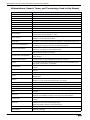
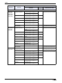
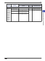
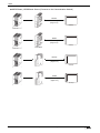
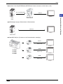
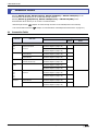
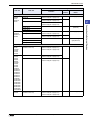
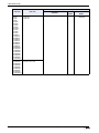
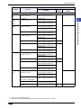
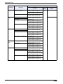
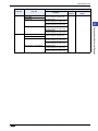
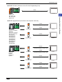
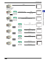
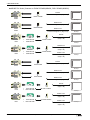
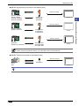
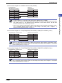
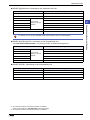
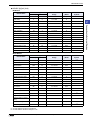
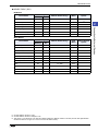
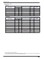
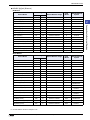
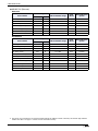
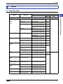
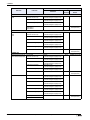
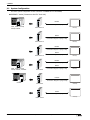
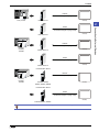
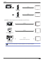
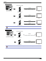
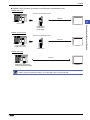
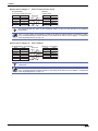
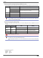
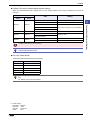
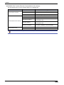
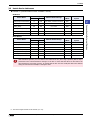
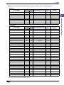
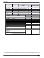
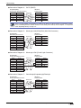
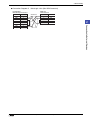
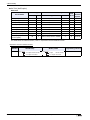
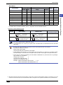
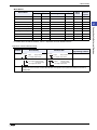
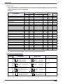
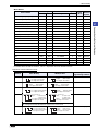
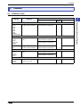
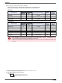
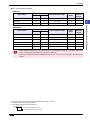
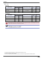
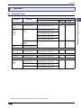
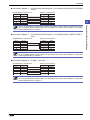
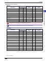
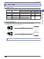
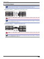
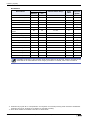
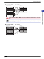
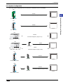
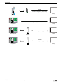
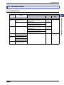
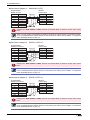
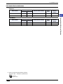
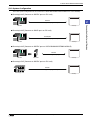
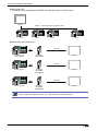
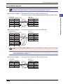
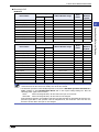
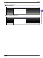
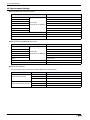
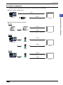
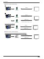
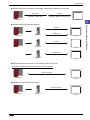
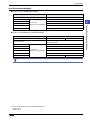
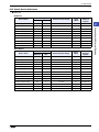
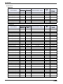
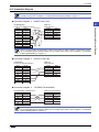
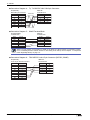
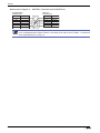
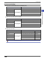
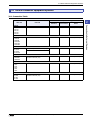
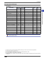
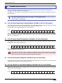
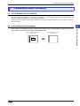
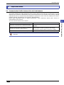
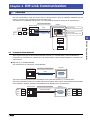
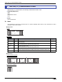
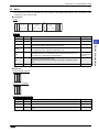
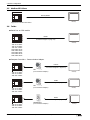
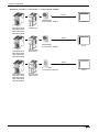
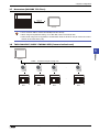
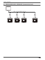
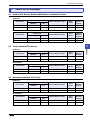
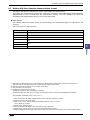
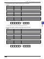
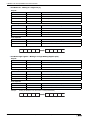
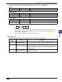
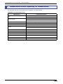
2 Mitsubishi Electric
RS422
Connection Diagram 10 (Page 2-29)
FX0S, FX1S, FX0N, FX1N,
FX1NC, FX2N, FX2NC,
FX3UC, FX3U, FX3G
Mitsubishi Electric Cable
RS422
FX-20P-CADP
Connection Diagram 4
(Page 2-27)
FX1N-422-BD
FX2N-422-BD
2
Connection to External Devices
FX1N
FX2N
MICRO/I
MICRO/I
RS422
Connection Diagram 10 (Page 2-29)
FX1N
FX2N
FX1N-422-BD
FX2N-422-BD
MICRO/I
RS422
Connection Diagram 5 (Page 2-27)
FX1N
FX2N
FX1N-232-BD
FX2N-232-BD
MICRO/I
RS422
Connection Diagram 11 (Page 2-29)
FX1S, FX1N
FX2N
FX1N-485-BD
FX2N-485-BD
RS485 4-wire
Connection Diagram 12 (Page 2-29)
MICRO/I
RS232C
Connection Diagram 8 (Page 2-28)
FX3UC, FX3U
FX3G
FX3U-232-BD
FX3G-232-BD
MICRO/I
RS485 4-wire
Connection Diagram 11 (Page 2-29)
FX3UC, FX3U
FX3G
FX3U-485-BD
FX3G-485-BD
RS485 2-wire
Connection Diagram 12 (Page 2-29)
WindO/I-NV4 External Device Setup Manual
MICRO/I
2-23
2 Mitsubishi Electric
● MELSEC-FX Series (Connects to FX2NC-232ADP/485ADP, FX3U-232ADP/485ADP)
RS232C
Connection Diagram 8 (Page 2-28)
FX2NC-232ADP
FX1NC
FX2NC
MICRO/I
RS485 4-wire
Connection Diagram 11 (Page 2-29)
FX2NC-485ADP
FX1NC
FX2NC
RS485 2-wire
Connection Diagram 12 (Page 2-29)
MICRO/I
RS232C
FX1N
FX2N
+
+
FX1N-CNV-BD
FX2N-CNV-BD
FX2NC-232ADP
Connection Diagram 8
(Page 2-28)
MICRO/I
RS4854-wire
Connection Diagram 11
(Page 2-29)
FX1N
FX2N
+
+
FX1N-CNV-BD
FX2N-CNV-BD
FX2NC-485ADP
RS485 2-wire
Connection Diagram 12
(Page 2-29)
MICRO/I
RS232C
FX3U-232ADP
FX3UC
Connection Diagram 8 (Page 2-28)
MICRO/I
RS485 4-wire
Connection Diagram 11 (Page 2-29)
FX3U-485ADP
FX3UC
RS485 2-wire
Connection Diagram 12 (Page 2-29)
MICRO/I
RS232C
FX3U
+
FX3U-CNV-BD
FX3G
+
FX3G-CNV-ADP
FX3U-232ADP
Connection Diagram 8
(Page 2-28)
MICRO/I
RS485 4-wire
Connection Diagram 11
(Page 2-29)
FX3U
+
FX3U-CNV-BD
FX3G
+
FX3G-CNV-ADP
FX2NC-485ADP
RS485 2-wire
Connection Diagram 12
(Page 2-29)
2-24
WindO/I-NV4 External Device Setup Manual
MICRO/I
2 Mitsubishi Electric
● MELSEC-Q/QnA Series (Connects to the Ethernet Unit)
Ethernet (TCP/IP)
Q00JCPU, Q00CPU
Q01CPU, Q02CPU
Q02HCPU, Q06HCPU
Q12HCPU, Q25HCPU
QJ71E71-100
QJ71E71-B5
QJ71E71-B2
MICRO/I
2
Q4ACPU, Q4ARCPU
Q3ACPU, Q2ACPU-S1
AJ71QE71N3-T
AJ71QE71N3-T
AJ71QE71N-B5
MICRO/I
Ethernet (TCP/IP)
Q2ASHCPU-S1,
Q2ASHCPU
Q2ASCPU-S1, Q2ASHCPU
A1SJ71QE71N3-T
A1SJ71QE71N-B2
A1SJ71QE71N-B5
MICRO/I
• Use a crossover cable to connect the MICRO/I and PLC directly.
• When using a hub (Ethernet switch), use a cable that can be used with the hub.
● MELSEC-FX Series (Connects to the Ethernet Unit)
Ethernet (TCP/IP)
FX3UC
FX3U
FX3U-ENET-L
MICRO/I
When connecting with MELSEC-FX3UC, FX2NC-CNV-IF or FX3UC-1PS-5V is required.
WindO/I-NV4 External Device Setup Manual
2-25
Connection to External Devices
Ethernet (TCP/IP)
2 Mitsubishi Electric
2.3 Connection Diagram
The connector types given in the Connection Diagrams are for the unit and not the cable. For details
regarding wiring, refer to Chapter 1 “3 Important Points Regarding Wiring” on page 1-4.
● Connection Diagram 1:
Computer Link Unit (RS232C)
PLC(RS232C):
D-sub 25-pin Female Connector
Name
FG
SD
RD
RS
CS
DR
SG
CD
ER
Pin No.
1
2
3
4
5
6
7
8
20
● Connection Diagram 2:
HG2G-5T:
Terminal block
Shield Wire
Pin No.
Name
SD
RD
RS
CS
SG
Computer Link Unit (RS485)
PLC(RS422/485): Terminal block
Name
FG
SDA
SDB
RDA
RDB
SG
Pin No.
1
2
3
4
5
HG2G-5T: Terminal block
Shield Wire
Pin No.
8
9
6
7
5
Name
RDA(RD+)
RDB(RD-)
SDA(SD+)
SDB(SD-)
SG
• There is no pin number corresponding to TERM on the HG2G-5T. When inserting a termination resistor,
use a Terminating Resistor Selector Switch. For the setting of the switch, refer to Chapter 1 “3
Important Points Regarding Wiring” on page 1-4.
• When using the QJ71C24 Serial Communication Unit, connect a terminator resistor in accordance with
the instruction manual.
● Connection Diagram 3:
Computer Link Unit (RS232C)
PLC(RS232C):
D-sub 9-pin Female Connector
Name
CD
RD
SD
ER
SG
DR
RS
CS
FG
2-26
Pin No.
1
2
3
4
5
6
7
8
Cover
HG2G-5T:
Terminal block
Shield Wire
Pin No.
1
2
3
4
5
Name
SD
RD
RS
CS
SG
WindO/I-NV4 External Device Setup Manual
2 Mitsubishi Electric
● Connection Diagram 4:
PLC, 2-port Adapter
PLC(RS422/485):
D-sub 25-pin Female Connector
Pin No.
2
15
3
16
4
17
5
18
7
8
13
20
21
Shield Wire
Pin No.
8
9
6
7
5
Name
RDA(RD+)
RDB(RD-)
SDA(SD+)
SDB(SD-)
SG
Internal
termination
resistor
330Ω
2
There is no pin number corresponding to TERM on the HG2G-5T. When inserting a termination resistor,
use a Terminating Resistor Selector Switch. For the setting of the switch, refer to Chapter 1 “3 Important
Points Regarding Wiring” on page 1-4.
● Connection Diagram 5:
FX2N-232-BD
PLC(RS232C):
D-sub 9-pin Male Connector
Name
CD
RD
SD
ER
SG
DR
RS
CS
FG
Pin No.
1
2
3
4
5
6
7
8
Cover
● Connection Diagram 6:
HG2G-5T:
Terminal block
Shield Wire
Pin No.
2
3
4
5
6
Name
SD
RD
RS
CS
SG
MELSEC-Q (Mitsubishi Electric Cable QC30R2)
PLC(RS232C):
D-sub 9-pin Female Connector
(cable side)
Name
RXD
TXD
DTR
GND
DSR
Pin No.
1
2
3
4
5
HG2G-5T:
Terminal block
Shield Wire
Pin No.
1
2
3
4
5
Name
SD
RD
RS
CS
SG
WindO/I-NV4 External Device Setup Manual
2-27
Connection to External Devices
Name
RD+
RDSD+
SDCS+
CSRS+
RSSG
SG
Vcc
HG2G-5T:
Terminal block
2 Mitsubishi Electric
● Connection Diagram 7:
MELSEC-Q (CPU Unit Programming Port)
PLC(RS232C):
Mini DIN 6-pin Connector
Name
RXD(RD)
TXD(SD)
SG
DSR(DR)
DTR(ER)
HG2G-5T:
Terminal block
Pin No.
1
2
3
4
5
Pin No.
1
2
3
4
5
6
Name
SD
RD
RS
CS
SG
Pin Assignment of Mini DIN 6-pin plug on the side of the MELSEC-Q series
5
6
3
4
1
2
● Connection Diagram 8:
FX2NC-232ADP/FX3U-232ADP/FC3U-232-BD
PLC(RS232C):
D-sub 9-pin Male Connector
Name
CD
RD(RXD)
SD(TXD)
ER(DTR)
SG(GND)
DR(DSR)
NC
NC
NC
HG2G-5T:
Terminal block
Pin No.
1
2
3
4
5
Pin No.
1
2
3
4
5
6
7
8
9
● Connection Diagram 9:
Computer Link Unit (RS485)
PLC(RS422/485):
D-sub 25-pin Male Connector
Name
FG
RDA
SDA
DSRA
DTRA
SG
SG
RDB
SDB
DSRB
STRB
Pin No.
1
2
3
4
5
7
8
15
16
17
18
Name
SD
RD
RS
CS
SG
HG2G-5T:
Terminal block
Shield Wire
Pin No.
8
9
6
7
5
Name
RDA(RD+)
RDB(RD-)
SDA(SD+)
SDB(SD-)
SG
There is no pin number corresponding to TERM on the HG2G-5T. When inserting a termination resistor,
use a Terminating Resistor Selector Switch. For the setting of the switch, refer to Chapter 1 “3 Important
Points Regarding Wiring” on page 1-4.
2-28
WindO/I-NV4 External Device Setup Manual
2 Mitsubishi Electric
● Connection Diagram 10: MELSEC-FX Series CPU (RS485)
PLC(RS422/485):
Mini DIN 8-pin Connector
Pin No.
7
4
2
1
3
6
Cover
Pin No.
8
9
6
7
5
Name
RDA(RD+)
RDB(RD-)
SDA(SD+)
SDB(SD-)
SG
2
• In case of HG2G-5T, a connection cable (part number: HG9Z-XC275) is available.
Please do not use the communication cables (part number: FC2A-KP1C and HG9Z-XC275) with FX3U
and FX3UC-32-MT-LT of the MELSEC-FX Series described in this manual because the Mini DIN
Connector interferes with the housing of the PLC.
• There is no pin number corresponding to TERM on the HG2G-5T. When inserting a termination resistor,
use a Terminating Resistor Selector Switch. For the setting of the switch, refer to Chapter 1 “3
Important Points Regarding Wiring” on page 1-4.
● Connection Diagram 11: FX1N/FX2N/FX3U/FX3G-485-BD, FX2NC/FX3U-485ADP (4-wire)
PLC(RS422/485): Terminal block
Name
SDA
SDB
RDA
RDB
SG
Pin No.
HG2G-5T: Terminal block
Pin No.
8
9
6
7
5
Name
RDA(RD+)
RDB(RD-)
SDA(SD+)
SDB(SD-)
SG
There is no pin number corresponding to TERM on the HG2G-5T. When inserting a termination resistor,
use a Terminating Resistor Selector Switch. For the setting of the switch, refer to Chapter 1 “3 Important
Points Regarding Wiring” on page 1-4.
● Connection Diagram 12: FX1N/FX2N/FX3U/FX3G-485-BD, FX2NC/FX3U-485ADP (2-wire)
PLC(RS422/485): Terminal block
Name
SDA
SDB
RDA
RDB
SG
Pin No.
HG2G-5T: Terminal block
Pin No.
8
9
6
7
5
Name
RDA(RD+)
RDB(RD-)
SDA(SD+)
SDB(SD-)
SG
There is no pin number corresponding to TERM on the HG2G-5T. When inserting a termination resistor,
use a Terminating Resistor Selector Switch. For the setting of the switch, refer to Chapter 1 “3 Important
Points Regarding Wiring” on page 1-4.
WindO/I-NV4 External Device Setup Manual
2-29
Connection to External Devices
Name
SDA
SDB
RDA
RDB
SG
SG
Shield
HG2G-5T:
Terminal block
2 Mitsubishi Electric
2.4 Environment Settings
● MELSEC-A Series: Connecting to the Computer Link Unit or CPU Unit Link Interface
Item
Setting
Interface
RS232C
RS485
Format 4 protocol mode
Transmission Control Protocol
Set the mode setting switch to 4.
Set the mode setting switch to 8.
Station Number*1
Set using the Station Number setting switch.
Baud Rate
1200, 2400, 4800, 9600 or 19200 bps
(set using the Transmission Specifications setting switch)
Use the same settings
as for the MICRO/I.
Data Bits
7 or 8 bits (set using the Transmission Specifications setting switch)
Stop Bits
1 or 2 stop bits (set using the Transmission Specifications setting switch)
Parity
None, Odd or Even (set using the Transmission Specifications setting
switch)
Checksum
Yes (set using the Transmission Specifications setting switch)
Write During RUN
Possible (set using the Transmission Specifications setting switch)
Transmission Side Termination Resistor
No
Yes (set using the Transmission
Specifications setting switch)
Receive Side Termination Resistor
No
Yes (set using the Transmission
Specifications setting switch)
Computer Link/Multi Drop Selection
Computer Link (set using the Transmission Specifications setting switch)
Note: Only set if this item is present.
For details, refer to the Link Unit manual.
● MELSEC-A Series: Connecting to the Programming Port or 2-port Adapter
Item
Setting
Interface
RS422
Baud Rate
9600 bps
Data Bits
Stop Bits
Parity
Use the same settings 8 bits
as for the MICRO/I.
1 stop bits
Odd
When connecting CPU unit for the connection, the PLC program scan time will increase when it starts
communicating with the MICRO/I. Check it under your actual operating conditions.
*1 Set a decimal number for the Station Number on MICRO/I.
2-30
WindO/I-NV4 External Device Setup Manual
2 Mitsubishi Electric
● MELSEC-Q/QnA Series: Connecting to the Computer Link Unit
Item
Setting
Interface
RS232C or RS422
Communication protocol
MC Protocol (Format 4)
Station Number*1
0
Baud Rate
Data Bits
Stop Bits
1200, 2400, 4800, 9600, 19200, 38400, 57600 or 115200 bps
2
7 or 8 bits
1 or 2 stop bits
Parity
None, Odd or Even
Checksum Code
Yes
Write During RUN
Possible
Connection to External Devices
Use the same
settings as for the
MICRO/I.
For details, refer to the Q-compatible Serial Communication Unit user manual (Basic).
● MELSEC-Q00CPU/Q01CPU: Connecting to the Programming Port
Select Use Serial Communication in the parameter setting of MELSEC-Q00CPU/Q01CPU.
Item
Station Number
Setting
*2
0
Baud Rate
Use the same
settings as for the
MICRO/I.
Data Bits
Stop Bits
19200, 38400, 57600 or 115200 bps
8 bits
1 stop bits
Parity
Odd
Checksum Code
Yes
● MELSEC-Q02CPU: Connecting to the Programming Port
Item
Setting
Baud Rate
9600, 19200, 38400, 57600 or 115200 bps
Data Bits
8 bits
Stop Bits
1 stop bits
Parity
Odd
*1 Set a decimal number for the Station Number on MICRO/I.
Setup the PLC settings in I/O allocation of the GX Developer.
*2 Set a decimal number for the Station Number on MICRO/I.
WindO/I-NV4 External Device Setup Manual
2-31
2 Mitsubishi Electric
● MELSEC-FX Series: Using Communication Driver MELSEC-FX(CPU), MELSEC-FX2N(CPU), MELSEC-
FX3UC(CPU)
Item
Setting
Interface
RS232C or RS422
Baud Rate
*1
9600, 19200, 38400, 57600 or 115200 bps
Use the same
settings as for the
MICRO/I.
Data Bits
Stop Bits
Parity
7 bits
1 stop bits
Even
• When connecting CPU unit for the connection, the PLC program scan time will increase when it starts
communicating with the MICRO/I. Check it under your actual operating conditions.
• To connect MELSEC-FX series PLC and MICRO/I, check the following two things.
- Unchecked the communication setting by the programming software.
- D8120 must be 0.
If the PLC is MELSEC-FX3U or MELSEC-3UC, check the follows:
If MICRO/I connects to CH1 on the PLC, D8400 must be 0.
If MICRO/I connects to CH2 on the PLC, D8420 must be 0.
● MELSEC-FX Series: Using Communication Driver MELSEC-FX(LINK)
Item
Setting
Interface
RS232C or RS422
Baud Rate
*2
1200, 2400, 4800, 9600, 19200 or 38400 bps
Use the same
settings as for the
MICRO/I.
Data Bits
Stop Bits
7 or 8 bits
1 or 2 stop bits
Parity
None, Odd or Even
Protocol
Special protocol communication
Sum check
Enable
Transmission Control Protocol
With Type 4 (CR, LF)
Station No.*3
00 to 0F
In the case of FX1S, FX1N, and FX1NC, there must be an interval time of two scan times or more
otherwise the command cannot be received after sending data for a command from an external device.
Confirm the scan time of PLC and set the transmission wait for MICRO/I.
Example: If the PLC scan time is 10 msec, set the transmission wait for the MICRO/I to 20 msec or more.
*1 The communication speed settings varies based on the PLC model. For details, refer to the PLC manual.
*2 The communication speed settings varies based on the PLC model. For details, refer to the FX Series User's Manual
(Communication Control Edition).
*3 Set a decimal number for the Station Number on MICRO/I.
2-32
WindO/I-NV4 External Device Setup Manual
2 Mitsubishi Electric
● MELSEC-Q/QnA: Connecting to Ethernet Unit
MICRO/I settings
Set the following items on the Project Settings dialog box in WindO/I-NV4.
Tab Name
Setting Name
Communication Interface
IP Address
Set the IP address of MICRO/I.
Subnet mask
Set the subnet mask of MICRO/I.
Default Gateway
Set the default gateway of MICRO/I.
IP Address
Set the IP address of PLC.
Port Number
Set the port number of PLC to communicate with MICRO/I.
2
This communication driver does not support MELSECNET/H and MELSECNET/10 network.
PLC Settings
Set the same settings as MICRO/I to IP Address and Local station Port No.
Item
Network
parameter
Operation Setting
Open Setting
setting
notes
Network type
Ethernet
*1
Starting I/O No.
0020
*2
Network No.
1
*2
Total stations
-
-
Group No.
0
*2
Station No.
1
*2
Mode
On line
*1
Communication data code
Binary code
*1
Initial Timing
Always wait for OPEN
*1
Input format
Decimal
*2
IP address
Set IP address of PLC
*2
Send frame setting
Ethernet
*1
Enable Write at RUN time
Check mark (enable)
*1
TCP Existence confirmation setting
Use the Keep Alive
*1
Protocol
TCP/IP
*1
Open system
Impassive open
*1
Fixed buffer
Send
*1
Fixed buffer communication
Procedure exist
*1
Pairing open
No pairs
*1
Existence confirmation
No confirm
*1
Local station Port No.
Set an arbitrary port number
Destination IP address
-
-
Dest. Port No.
-
-
IP Address
*2*3
For details, refer to the Q Corresponding Ethernet Interface Module User’s Manual or Q Corresponding
Ethernet Interface Module User’s Manual.
*1 The setting of the above-mentioned is recommended.
*2 Set it according to the environment.
*3 MICRO/I is set by the decimal number though PLC is set by the hexadecimal number.
WindO/I-NV4 External Device Setup Manual
2-33
Connection to External Devices
Communication Driver
Network
Setting
2 Mitsubishi Electric
● MELSEC-FX: Connecting to Ethernet Unit
MICRO/I settings
Set the following items on the Project Settings dialog box in WindO/I-NV4.
Tab Name
Setting Name
Communication Interface
Communication Driver Network
Setting
IP Address
Set the IP address of MICRO/I.
Subnet Mask
Set the subnet mask of MICRO/I.
Default Gateway
Set the default gateway of MICRO/I.
IP Address
Set the IP address of CPU Unit or Link Unit.
Port Number
Set the port number of CPU Unit or Link Unit in.
PLC Settings
Ethernet Operation Setting
Item
Setting
Received data code setting
Binary code
Initial Timing
Always wait for OPEN (Communication possible during STOP)
IP Address
Set IP address of PLC
Send frame setting
Ethernet (V2.0)
TCP Existence confirmation setting
Use the Keep Alive
Open Setting
Item
2-34
Setting
Connection
Use 3 or 4
Protocol
TCP/IP
Open system
Impassive open (MC)
Existence confirmation
No confirm
Local station Port No. (Decimal)
Set an arbitrary port number
1025 to 5548 or 5552 to 65534 (Default: 1025)
WindO/I-NV4 External Device Setup Manual
2 Mitsubishi Electric
2.5 Usable Device Addresses
● MELSEC-AnA (Link)
Bit Device
Device Type
Address Number Range
Read
/Write
Address Numeral
System
X
0 to 1FFF
R
*1
Y
Y
0 to 1FFF
R/W
*1
Internal Relay
M
M
0 to 8191
R/W
Link Relay
B
B
0 to 1FFF
R/W
Latch Relay
L
L
0 to 8191
R/W
Timer (contact)
TS
T
0 to 2047
R
Timer (coil)
TC
T
0 to 2047
R/W
Counter (contact)
CS
C
0 to 1023
R
Counter (coil)
CC
C
0 to 1023
R/W
Special Internal Relay
SM
SM
9000 to 9255
R
F
F
0 to 2047
R/W
Address Number Range
Read
/Write
Address Numeral
System
Device Name
MICRO/I
PLC
Input Relay
X
Output Relay
*1
Word Device
Device Name
Device Type
MICRO/I
PLC
Input Relay
WX
X
0 to 1FF0
R
*1*2
Output Relay
WY
Y
0 to 1FF0
R/W
*1*2
Internal Relay
WM
M
0 to 8176
R/W
*2
Link Relay
WB
B
0 to 1FF0
R/W
*1*2
Latch Relay
WL
L
0 to 8176
R/W
*2
Timer (current value)
TN
T
0 to 2047
R
Counter (current value)
CN
C
0 to 1023
R
Data Register
D
D
0 to 8191
R/W
Link Register
W
W
0 to 1FFF
R/W
*1
Annunciator
WF
F
0 to 2032
R/W
*2
WSM
SM
9000 to 9240
R
*2
SD
SD
9000 to 9255
R
File register
R
R
0 to 8191
R/W
Expansion file register
ER
ZR
0 to 58191
R/W
Special Internal Relay
Special register
*1 Set this address number in hexadecimal.
*2 Set this address number in multiples of 16.
WindO/I-NV4 External Device Setup Manual
2-35
Connection to External Devices
Annunciator
2
2 Mitsubishi Electric
● MELSEC-AnN (LINK)
Bit Device
Device Type
Address Number Range
Read
/Write
Address Numeral
System
X
0 to 7FF
R
*1
Y
Y
0 to 7FF
R/W
*1
Internal Relay
M
M
0 to 2047
R/W
Link Relay
B
B
0 to 3FF
R/W
Latch Relay
L
L
0 to 2047
R/W
Timer (contact)
TS
T
0 to 255
R
Timer (coil)
TC
T
0 to 255
R/W
Counter (contact)
CS
C
0 to 255
R
Counter (coil)
CC
C
0 to 255
R/W
Special Internal Relay
SM
SM
9000 to 9255
R
F
F
0 to 255
R/W
Address Number Range
Read
/Write
Address Numeral
System
Device Name
MICRO/I
PLC
Input Relay
X
Output Relay
Annunciator
*1
Word Device
Device Name
Device Type
MICRO/I
PLC
Input Relay
WX
X
0 to 7F0
R
*1*2
Output Relay
WY
Y
0 to 7F0
R/W
*1*2
Internal Relay
WM
M
0 to 2032
R/W
*2
Link Relay
WB
B
0 to 3F0
R/W
*1*2
Latch Relay
WL
L
0 to 2032
R/W
*2
Timer (current value)
TN
T
0 to 255
R
Counter (current value)
CN
C
0 to 255
R
Data Register
D
D
0 to 1023
R/W
Link Register
W
W
0 to 3FF
R/W
*1
Annunciator
WF
F
0 to 240
R/W
*2
WSM
SM
9000 to 9240
R
*2
SD
SD
9000 to 9255
R
R
R
0 to 8191
R/W
Special Internal Relay
Special register
File register
*1 Set this address number in hexadecimal.
*2 Set this address number in multiples of 16.
2-36
WindO/I-NV4 External Device Setup Manual
2 Mitsubishi Electric
● MELSEC-AnA (CPU)
Bit Device
Device Type
Address Number Range
Read
/Write
Address Numeral
System
X
0 to 7FF
R
*1
Y
Y
0 to 7FF
R/W
*1
Internal Relay
M
M
0 to 8191
R/W
Link Relay
B
B
0 to 7FF
R/W
Latch Relay
L
L
0 to 8191
R/W
Timer (contact)
TS
T
0 to 2047
R
Timer (coil)
TC
T
0 to 2047
R/W
Counter (contact)
CS
C
0 to 1023
R
Counter (coil)
CC
C
0 to 1023
R/W
Special Internal Relay
SM
SM
9000 to 9255
R
F
F
0 to 2047
R/W
Address Number Range
Read
/Write
Address Numeral
System
Device Name
MICRO/I
PLC
Input Relay
X
Output Relay
*1
Word Device
Device Name
Device Type
MICRO/I
PLC
Input Relay
WX
X
0 to 7F0
R
*1*2
Output Relay
WY
Y
0 to 7F0
R/W
*1*2
Internal Relay
WM
M
0 to 8176
R/W
*2
Link Relay
WB
B
0 to 7F0
R/W
*1*2
Latch Relay
WL
L
0 to 8176
R/W
*2
Timer (current value)
TN
T
0 to 2047
R
Counter (current value)
CN
C
0 to 1023
R
Data Register
D
D
0 to 6143
R/W
Link Register
W
W
0 to FFF
R/W
*1
Annunciator
WF
F
0 to 2032
R/W
*2
WSM
SM
9000 to 9240
R
*2
SD
SD
9000 to 9255
R
Special Internal Relay
Special Register
*1 Set this address number in hexadecimal.
*2 Set this address number in multiples of 16.
WindO/I-NV4 External Device Setup Manual
2-37
Connection to External Devices
Annunciator
2
2 Mitsubishi Electric
● MELSEC-AnN (CPU)
Bit Device
Device Type
Address Number Range
Read
/Write
Address Numeral
System
X
0 to 7FF
R
*1
Y
Y
0 to 7FF
R/W
*1
Internal Relay
M
M
0 to 2047
R/W
Link Relay
B
B
0 to 3FF
R/W
Latch Relay
L
L
0 to 2047
R/W
Timer (contact)
TS
T
0 to 255
R
Timer (coil)
TC
T
0 to 255
R/W
Counter (contact)
CS
C
0 to 255
R
Counter (coil)
CC
C
0 to 255
R/W
Special Internal Relay
SM
SM
9000 to 9255
R
F
F
0 to 255
R/W
Address Number Range
Read
/Write
Address Numeral
System
Device Name
MICRO/I
PLC
Input Relay
X
Output Relay
Annunciator
*1
Word Device
Device Name
Device Type
MICRO/I
PLC
Input Relay
WX
X
0 to 7F0
R
*1*2
Output Relay
WY
Y
0 to 7F0
R/W
*1*2
Internal Relay
WM
M
0 to 2032
R/W
*2
Link Relay
WB
B
0 to 3F0
R/W
*1*2
Latch Relay
WL
L
0 to 2032
R/W
*2
Timer (current value)
TN
T
0 to 255
R
Counter (current value)
CN
C
0 to 255
R
Data Register
D
D
0 to 1023
R/W
Link Register
W
W
0 to 3FF
R/W
*1
Annunciator
WF
F
0 to 240
R/W
*2
WSM
SM
9000 to 9240
R
*2
SD
SD
9000 to 9255
R
Special Internal Relay
Special Register
*1 Set this address number in hexadecimal.
*2 Set this address number in multiples of 16.
2-38
WindO/I-NV4 External Device Setup Manual
2 Mitsubishi Electric
● MELSEC-AnU (CPU)
Bit Device
Device Type
Address Number Range
Read
/Write
Address Numeral
System
X
0 to 1FFF
R
*1
Y
Y
0 to 1FFF
R/W
*1
Internal Relay
M
M
0 to 8191
R/W
Link Relay
B
B
0 to 1FFF
R/W
Latch Relay
L
L
0 to 8191
R/W
Timer (contact)
TS
T
0 to 2047
R
Timer (coil)
TC
T
0 to 2047
R/W
Counter (contact)
CS
C
0 to 1023
R
Counter (coil)
CC
C
0 to 1023
R/W
Special Internal Relay
SM
SM
9000 to 9255
R
F
F
0 to 2047
R/W
Address Number Range
Read
/Write
Address Numeral
System
Device Name
MICRO/I
PLC
Input Relay
X
Output Relay
*1
Word Device
Device Name
Device Type
MICRO/I
PLC
Input Relay
WX
X
0 to 1FF0
R
*1*2
Output Relay
WY
Y
0 to 1FF0
R/W
*1*2
Internal Relay
WM
M
0 to 8176
R/W
*2
Link Relay
WB
B
0 to 1FF0
R/W
*1*2
Latch Relay
WL
L
0 to 8176
R/W
*2
Timer (current value)
TN
T
0 to 2047
R
Counter (current value)
CN
C
0 to 1023
R
Data Register
D
D
0 to 8191
R/W
Link Register
W
W
0 to 1FFF
R/W
*1
Annunciator
WF
F
0 to 2032
R/W
*2
WSM
SM
9000 to 9240
R
*2
SD
SD
9000 to 9255
R
Special Internal Relay
Special Register
*1 Set this address number in hexadecimal.
*2 Set this address number in multiples a multiplier of 16.
WindO/I-NV4 External Device Setup Manual
2-39
Connection to External Devices
Annunciator
2
2 Mitsubishi Electric
● MELSEC-A1S/A2C (CPU)
Bit Device
Device Type
Address Number Range
Read
/Write
Address Numeral
System
X
0 to 1FF
R
*1
Y
Y
0 to 1FF
R/W
*1
Internal Relay
M
M
0 to 2047
R/W
Link Relay
B
B
0 to 3FF
R/W
Latch Relay
L
L
0 to 2047
R/W
Timer (contact)
TS
T
0 to 255
R
Timer (coil)
TC
T
0 to 255
R/W
Counter (contact)
CS
C
0 to 255
R
Counter (coil)
CC
C
0 to 255
R/W
Special Internal Relay
SM
SM
9000 to 9255
R
F
F
0 to 255
R/W
Address Number Range
Read
/Write
Address Numeral
System
Device Name
MICRO/I
PLC
Input Relay
X
Output Relay
Annunciator
*1
Word Device
Device Name
Device Type
MICRO/I
PLC
Input Relay
WX
X
0 to 1F0
R
*1*2
Output Relay
WY
Y
0 to 1F0
R/W
*1*2
Internal Relay
WM
M
0 to 2032
R/W
*2
Link Relay
WB
B
0 to 3F0
R/W
*1*2
Latch Relay
WL
L
0 to 2032
R/W
*2
Timer (current value)
TN
T
0 to 255
R
Counter (current value)
CN
C
0 to 255
R
Data Register
D
D
0 to 1023
R/W
Link Register
W
W
0 to 3FF
R/W
*1
Annunciator
WF
F
0 to 240
R/W
*2
WSM
SM
9000 to 9240
R
*2
SD
SD
9000 to 9255
R
R
R
0 to 8191
R/W
Special Internal Relay
Special Register
File Register
• File Register is not available when Memory Cassettes is used.
• File Register is tested with the CPU Unit: MELSEC-A1S/A1SH/A1SJH/A2SH/A2C. Don’t use the File
Register with expect these CPU Unit.
• When File Register is used, restart MICRO/I after changing PLC parameter.
*1 Set this address number in hexadecimal.
*2 Set this address number in multiples of 16.
2-40
WindO/I-NV4 External Device Setup Manual
2 Mitsubishi Electric
● MELSEC-Q/QnA (Link)
Bit Device
Device Type
PLC
Internal Relay
M
M
0 to 32767
R/W
Input Relay
X
X
0 to 1FFF
R
*1
Output Relay
Y
Y
0 to 1FFF
R/W
*1
Link Special Relay
SB
SB
0 to 7FF
R/W
*1
Link Relay
B
B
0 to 7FFF
R/W
*1
Latch Relay
Read
/Write
L
L
0 to 32767
R/W
Timer (contact)
TS
T
0 to 8191
R
Timer (coil)
TC
T
0 to 8191
R/W
Counter (contact)
CS
C
0 to 8191
R
Counter (coil)
CC
C
0 to 8191
R/W
Special Relay
SM
SM
0 to 2047
R
Annunciator
F
F
0 to 32767
R/W
Retentive Timer (contact)
SS
ST
0 to 2047
R
Retentive Timer (coil)
SC
ST
0 to 2047
R/W
Address Numeral
System
2
Connection to External Devices
MICRO/I
Address Number
Range
Device Name
Step Relay
S
S
0 to 32767
R/W
Edge Relay
V
V
0 to 32767
R/W
MICRO/I
PLC
Address Number
Range
Read
/Write
Address Numeral
System
Input Relay
WX
X
0 to 1FF0
R
*1*2
Output Relay
WY
Y
0 to 1FF0
R/W
*1*2
Internal Relay
WM
M
0 to 32752
R/W
*2
Link Special Relay
WSB
SB
0 to 7F0
R/W
*1*2
Link Relay
WB
B
0 to 7FF0
R/W
*1*2
Latch Relay
WL
L
0 to 32752
R/W
*2
Timer (current value)
TN
T
0 to 8191
R
Counter (current value)
CN
C
0 to 8191
R
Data Register
D
D
0 to 25599
R/W
Link Register
W
W
0 to 24FF
R/W
File register
R
R
0 to 32767
R/W
Annunciator
WF
F
0 to 32752
R/W
*2
Special Relay
WSM
SM
0 to 2032
R
*2
Special register
SD
SD
0 to 2047
R
Edge Relay
WV
V
0 to 32752
R/W
*2
Step Relay
WS
S
0 to 32752
R/W
*2
Retentive Timer (current
value)
SN
ST
0 to 2047
R/W
Special Link Register
SW
SW
0 to 7FF
R/W
*1
Ext File Register
ZR
ZR
0 to FFFF
R/W
*1
Word Device
Device Name
Device Type
*1
*1 Set this address number in hexadecimal.
*2 Set this address number in multiples of 16.
WindO/I-NV4 External Device Setup Manual
2-41
2 Mitsubishi Electric
● MELSEC-Q (CPU)
Bit Device
Device Name
Device Type
Address Number Range
Read
/Write
Address Numeral
System
MICRO/I
PLC
Internal Relay
M
M
0 to 32767
R/W
Input Relay
X
X
0 to 1FFF
R
*1
Output Relay
Y
Y
0 to 1FFF
R/W
*1
Link Special Relay
SB
SB
0 to 7FF
R/W
*1
Link Relay
B
B
0 to 1FFF
R/W
*1
Latch Relay
L
L
0 to 32767
R/W
Annunciator
F
F
0 to 32767
R/W
Step Relay
S
S
0 to 8191
R/W
Edge Relay
V
V
0 to 32767
R/W
Timer (contact)
TS
T
0 to 23087
R
Timer (coil)
TC
T
0 to 23087
R/W
Counter (contact)
CS
C
0 to 23087
R
Counter (coil)
CC
C
0 to 23087
R/W
Retentive Timer (contact)
SS
ST
0 to 23087
R
Retentive Timer (coil)
SC
ST
0 to 23087
R/W
Special Relay
SM
SM
0 to 2047
R
Address Number Range
Read
/Write
Address Numeral
System
Word Device
Device Name
Device Type
MICRO/I
PLC
Input Relay
WX
X
0 to 1FF0
R
*1*2
Output Relay
WY
Y
0 to 1FF0
R/W
*1*2
Internal Relay
WM
M
0 to 32752
R/W
*2
Link Relay
WB
B
0 to 7FF0
R/W
*1*2
Latch Relay
WL
L
0 to 32752
R/W
*2
Annunciator
WF
F
0 to 32752
R/W
*2
Edge Relay
WV
V
0 to 32752
R/W
*2
Step Relay
WS
S
0 to 8176
R/W
*2
Timer (current value)
TN
T
0 to 23087
R
Counter (current value)
CN
C
0 to 23087
R
Retentive Timer (current
value)
SN
ST
0 to 23087
R/W
Data Register
D
D
0 to 25983
R/W
Link Register
W
W
0 to 657F
R/W
Special Relay
WSM
SM
0 to 2032
R
*2
Link Special Relay
WSB
SB
0 to 7F0
R/W
*1*2
Special Register
SD
SD
0 to 2047
R
Special link Register
SW
SW
0 to 7FF
R/W
File Register
R
R
0 to 32767
R/W
Extend file Register
ZR
ZR
0 to 131072
R/W
*1 Set this address number in hexadecimal.
*2 Set this address number in multiples of 16.
2-42
WindO/I-NV4 External Device Setup Manual
2 Mitsubishi Electric
● MELSEC-FX (CPU)
Bit Device
Device Type
Address Number Range
Read
/Write
Address Numeral
System
X
0 to 337
R
*1
Y
Y
0 to 337
R/W
*1
Internal Relay
M
M
0 to 1535
R/W
Timer (contact)
TS
T
0 to 255
R
Counter (contact)
CS
C
0 to 255
R
S
S
0 to 999
R/W
Address Number Range
Read
/Write
Address Numeral
System
Device Name
MICRO/I
PLC
Input Relay
X
Output Relay
Word Device
Device Name
Device Type
MICRO/I
PLC
Input Relay
WX
X
0 to 320
R
*1*2
Output Relay
WY
Y
0 to 320
R/W
*1*2
Internal Relay
WM
M
0 to 1520
R/W
*2
Timer (current value)
TN
T
0 to 255
R
Counter (current value)
CN
C
0 to 199
R
DCN
C
2000 to 2551
R
D
D
0 to 999
R/W
WS
WS
0 to 976
R/W
32-Bit Counter (current value)
Data Register
State
*3
*2
*1 Set this address number in octal.
*2 Set this address number in multiples of 16.
*3 This device is a 32-bit device. The first three digits indicate the address number in decimal, and the last digit indicates
whether the data is an upper or a lower word of 32-bit data in binary.
WindO/I-NV4 External Device Setup Manual
2-43
Connection to External Devices
State
2
2 Mitsubishi Electric
● MELSEC-FX2N (CPU)
Bit Device
Device Type
Address Number Range
Read
/Write
Address Numeral
System
X
0 to 337
R
*1
Y
Y
0 to 337
R/W
*1
Internal Relay
M
M
0 to 3071
R/W
Timer (Relay)
TS
T
0 to 255
R
Device Name
MICRO/I
PLC
Input Relay
X
Output Relay
Counter (Relay)
CS
C
0 to 255
R
Special Int. Relay
SM
SM
8000 to 8255
R
S
S
0 to 999
R/W
Address Number Range
Read
/Write
Address Numeral
System
State
Word Device
Device Name
Device Type
MICRO/I
PLC
Input Relay
WX
X
0 to 360
R
*1*2
Output Relay
WY
Y
0 to 360
R/W
*1*2
Internal Relay
WM
M
0 to 3056
R/W
*2
Timer (current value)
TN
T
0 to 255
R
Counter (current value)
CN
C
0 to 199
R
DCN
C
2000 to 2551
R
D
D
0 to 7999
R/W
WS
S
0 to 976
R/W
*2
WSM
SM
8000 to 8240
R
*2
SD
SD
8000 to 8255
R
32-Bit Counter (current value)
Data Register
State
Special Int. Relay
Special Register
*3
*1 Set this address number in octal.
*2 Set this address number in multiples of 16.
*3 This device is a 32-bit device. The first three digits indicate the address number in decimal, and the last digit indicates
whether the data is an upper or a lower word of 32-bit data in binary.
2-44
WindO/I-NV4 External Device Setup Manual
2 Mitsubishi Electric
● MELSEC-FX3UC (CPU)
Bit Device
Device Type
Address Number Range
Read
/Write
Address Numeral
System
X
0 to 377
R
*1
Y
Y
0 to 377
R/W
*1
Internal Relay
M
M
0 to 7679
R/W
Timer (Relay)
TS
T
0 to 511
R
Device Name
MICRO/I
PLC
Input Relay
X
Output Relay
2
CS
C
0 to 255
R
Special Internal Relay
SM
SM
8000 to 8511
R
S
S
0 to 4095
R/W
Address Number Range
Read
/Write
Address Numeral
System
State
Word Device
Device Name
Device Type
MICRO/I
PLC
Input Relay
WX
X
0 to 360
R
*1*2
Output Relay
WY
Y
0 to 360
R/W
*1*2
Internal Relay
WM
M
0 to 7664
R/W
*2
Timer (current value)
TN
T
0 to 511
R
Counter (current value)
CN
C
0 to 199
R
DCN
C
2000 to 2551
R/W
D
D
0 to 7999
R/W
WS
S
0 to 4080
R/W
*2
Special Internal Relay
WSM
SM
8000 to 8496
R
*2
Special Data Register
SD
SD
8000 to 8511
R
R
R
0 to 32767
R/W
32-bit counter (current value)
Data Register
State
Extended Register
*3
*1 Set this address number in octal.
*2 Set this address number in multiples of 16.
*3 This device is a 32-bit device. The first three digits indicate the address number in decimal, and the last digit indicates
whether the data is an upper or a lower word of 32-bit data in binary.
WindO/I-NV4 External Device Setup Manual
2-45
Connection to External Devices
Counter (Relay)
2 Mitsubishi Electric
● MELSEC-FX (LINK)
Bit Device
Device Name
Device Type
Address Number Range
Read
/Write
Address Numeral
System
0 to 7679
R/W
Decimal
MICRO/I
PLC
Int. Relay
M
M
Input Relay
X
X
0 to 377
R/W
Octal
Output Relay
Y
Y
0 to 377
R/W
Octal
Timer Relay (contact)
TS
T
0 to 511
R/W
Decimal
Counter Relay (contact)
CS
C
0 to 255
R/W
Decimal
Special Internal Relay
SM
SM
8000 to 8511
R/W
Decimal
S
S
0 to 4095
R/W
Decimal
Address Number Range
Read
/Write
Address Numeral
System
State
Word Device
Device Name
Device Type
MICRO/I
PLC
D
D
0 to 7999
R/W
Decimal
Input Relay (word)
WX
X
0 to 360
R/W
Octal*1
Output Relay (word)
WY
Y
0 to 360
R/W
Octal*1
Int. Relay (word)
WM
M
0 to 7664
R/W
Decimal*1
Timer (Current Value)
TN
T
0 to 511
R/W
Decimal
Counter (Current Value)
CN
C
0 to 199
R/W
Decimal
State (word)
WS
S
0 to 4080
R/W
Decimal*1
WSM
M
8000 to 8496
R/W
Decimal*1
SD
D
8000 to 8511
R/W
Decimal
DCN
C
2000 to 2511
R/W
*2
R
R
0 to 32767
R/W
Decimal
Data Register
Special Internal Relay (word)
Special Data Register
32-bit counter (current value)
Extended Register
*1 Set this address number in hexadecimal.
*2 This is a 32-bit device address. The first three digits indicate the address number in decimal, and the last digit indicates
whether the data is an upper or a lower word of 32-bit data in binary.
2-46
WindO/I-NV4 External Device Setup Manual
2 Mitsubishi Electric
● MELSEC-Q/QnA (Ethernet)
Bit Device
Device Name
Device Type
Address Number Range
Read
/Write
Address Numeral
System
000000 to 002047
R
Decimal
PLC
SM
SM
Input Relay (bit)
X
X
000000 to 001FFF
R
Hexadecimal
Output Relay (bit)
Y
Y
000000 to 001FFF
R/W
Hexadecimal
Internal Relay (bit)
M
M
000000 to 475135
R/W
Decimal
Latch Relay (bit)
L
L
000000 to 475135
R/W
Decimal
Annunciator (bit)
F
F
000000 to 475135
R/W
Decimal
Edge Relay (bit)
V
V
000000 to 475135
R/W
Decimal
Link Relay (bit)
B
B
000000 to 073FFF
R/W
Hexadecimal
Timer (contact)
TS
TS
000000 to 475135
R
Decimal
Timer (coil)
TC
TC
000000 to 475135
R/W
Decimal
Retentive Timer (contact)
SS
SS
000000 to 475135
R
Decimal
Retentive Timer (coil)
SC
SC
000000 to 475135
R/W
Decimal
Counter (contact)
CS
CS
000000 to 475135
R
Decimal
Counter (coil)
CC
CC
000000 to 475135
R/W
Decimal
Link Special Relay (bit)
SB
SB
000000 to 0007FF
R/W
Decimal
Step Relay (bit)
S
S
000000 to 008191
R/W
Decimal
Address Number Range
Read
/Write
Address Numeral
System
Special Relay (bit)
Word Device
Device Name
Device Type
MICRO/I
PLC
Special Register
SD
SD
000000 to 002047
R
Decimal
Data Register
D
D
000000 to 029695
R/W
Decimal
Link Register
W
W
000000 to 0073FF
R/W
Hexadecimal
Timer (current value)
TN
TN
000000 to 029695
R
Decimal
Retentive Timer (current value)
SN
SN
000000 to 029695
R/W
Decimal
Counter (current value)
CN
CN
000000 to 029695
R
Decimal
Special Link Register
SW
SW
000000 to 0007FF
R/W
Hexadecimal
File Register
R
R
000000 to 032767
R/W
Decimal
Extend file Register
ZR
ZR
000000 to 0FE7FF
R/W
Hexadecimal
Special Relay (word)
WSM
SM
000000 to 002032
R
Decimal*1
Input Relay (word)
WX
X
000000 to 001FF0
R
Hexadecimal*1
Output Relay (word)
WY
Y
000000 to 001FF0
R/W
Hexadecimal*1
Internal Relay (word)
WM
M
000000 to 475120
R/W
Decimal*1
Latch Relay (word)
WL
L
000000 to 475120
R/W
Decimal*1
Annunciator (word)
WF
F
000000 to 475120
R/W
Decimal*1
Edge Relay (word)
WV
V
000000 to 475120
R/W
Decimal*1
Link Relay (word)
WB
B
000000 to 073FF0
R/W
Hexadecimal*1
Link Special Relay (word)
WSB
SB
000000 to 0007F0
R/W
Hexadecimal*1
Step Relay (word)
WS
S
000000 to 008176
R/W
Decimal*1
*1 Set this address number in multiples of 16.
WindO/I-NV4 External Device Setup Manual
2-47
2
Connection to External Devices
MICRO/I
2 Mitsubishi Electric
● MELSEC-FX (Ethernet)
Bit Device
Device Name
Device Type
Address Number Range
Read
/Write
Address Numeral
System
0 to 7679
R/W
Decimal
MICRO/I
PLC
Int. Relay
M
M
Input Relay
X
X
0 to 377
R
Octal
Output Relay
Y
Y
0 to 377
R/W
Octal
Timer Relay (contact)
TS
T
0 to 511
R
Decimal
Counter Relay (contact)
CS
C
0 to 255
R
Decimal
Special Internal Relay
SM
SM
8000 to 8511
R
Decimal
S
S
0 to 4095
R/W
Decimal
Address Number Range
Read
/Write
Address Numeral
System
State
Word Device
Device Name
Device Type
MICRO/I
PLC
D
D
0 to 7999
R/W
Decimal
Input Relay (word)
WX
X
0 to 360
R
Octal
Output Relay (word)
WY
Y
0 to 360
R/W
Octal
Int. Relay (word)
WM
M
0 to 7664
R/W
Decimal
Data Register
Timer (Current Value)
TN
T
0 to 511
R
Decimal
Counter (Current Value)
CN
C
0 to 199
R
Decimal
State (word)
WS
S
0 to 4080
R/W
Decimal
WSM
M
8000 to 8496
R
Decimal
SD
D
8000 to 8511
R
Decimal
DCN
C
2000 to 2511
R
*1
R
R
0 to 32767
R/W
Decimal
Special Internal Relay (word)
Special Data Register
32-bit counter (current value)
Extended Register
*1 This device is a 32-bit device. The first three digits indicate the address number in decimal, and the last digit indicates
whether the data is an upper or a lower word of 32-bit data in binary.
2-48
WindO/I-NV4 External Device Setup Manual
3 OMRON
3
OMRON
3.1 Connection Table
WindO/I-NV4 Settings
CPU unit
Link unit
Interface
Communication
Driver
SYSMAC C series
SYSMAC C
C500
C500F
C1000H
C2000
C2000H
C120-LK201-V1
RS232C
Connection Diagram 1 (Page 2-58)
ER
C120-LK202-V1
RS422/485 4-wire
Connection Diagram 2 (Page 2-58)
None
C500-LK201-V1
RS232C
Connection Diagram 1 (Page 2-58)
ER
RS422/485 4-wire
Connection Diagram 2 (Page 2-58)
None
RS232C
Connection Diagram 1 (Page 2-58)
ER
RS422/485 4-wire
Connection Diagram 3 (Page 2-59)
None
RS232C
Connection Diagram 1 (Page 2-58)
ER
RS422/485 4-wire
Connection Diagram 3 (Page 2-59)
None
C200H-LK201
RS232C
Connection Diagram 1 (Page 2-58)
ER
C200H-LK202
RS422/485 4-wire
Connection Diagram 2 (Page 2-58)
None
C200H-LK201
RS232C
Connection Diagram 1 (Page 2-58)
ER
C200H-LK202
RS422/485 4-wire
Connection Diagram 2 (Page 2-58)
None
C200HW-COM02/COM04
/COM05/COM06
RS232C
Connection Diagram 6 (Page 2-59)
C200HW-COM03/COM06
RS422/485 4-wire
Connection Diagram 7 (Page 2-59)
C120-LK201-V1
RS232C
Connection Diagram 1 (Page 2-58)
ER
C120-LK202-V1
RS422/485 4-wire
Connection Diagram 2 (Page 2-58)
None
C20H
C28H
C40H
C60H
Not required
(connects to CPU unit)
RS232C
Connection Diagram 4 (Page 2-59)
C200HE-CPU42
C200HG-CPU43/63
C200HX-CPU44/64
Not required
(connects to CPU unit)
RS232C
Connection Diagram 6 (Page 2-59)
CPM1
CPM1A
CPM2A
CPM1-CIF01
RS232C
Connection Diagram 5 (Page 2-59)
CPM1-CIF11
RS422/485 4-wire
Connection Diagram 8 (Page 2-60)
C200HS-CPU21/23/31/33
CQM1H
Not required
(connects to CPU unit)
RS232C
Connection Diagram 5 (Page 2-59)
CPM2A
Not required
(connects to CPU unit)
RS232C
Connection Diagram 5 (Page 2-59)
C500-LK203
C1000HF
C200HS
C200HE
C200HG
C200HX
C120
C120F
C500-LK203
WindO/I-NV4 External Device Setup Manual
SYSMAC C series
2-49
2
Connection to External Devices
Flow
Control
3 OMRON
WindO/I-NV4 Settings
CPU unit
Link unit
Interface
Flow
Control
Communication
Driver
None
SYSMAC CS1 series
-
SYSMAC CS1/CJ
series(Ethernet)
None
SYSMAC CS1 series
-
SYSMAC CS1/CJ
series(Ethernet)
None
SYSMAC CS1 series
-
SYSMAC CS1/CJ
series(Ethernet)
None
SYSMAC CS1 series
-
SYSMAC CS1/CJ
series(Ethernet)
SYSMAC CS1
CS1G
CS1H
Not required
(connects to CPU unit)
RS232C
Connection Diagram 6 (Page 2-59)
CS1W-SCB41 (port1)
RS232C
Connection Diagram 6 (Page 2-59)
CS1W-SCB41 (port2)
RS422/485 4-wire
Connection Diagram 7 (Page 2-59)
CS1W-ENT01
CS1W-ENT11
CS1W-ENT21
Ethernet
Not required
(connects to CPU unit)
RS232C
Connection Diagram 6 (Page 2-59)
CJ1W-SCU21-V1
RS232C
Connection Diagram 6 (Page 2-59)
CJ1W-SCU31-V1
RS422/485 4-wire
Connection Diagram 7 (Page 2-59)
CJ1W-SCU41-V1(port1)
RS422/485 4-wire
Connection Diagram 7 (Page 2-59)
CJ1W-SCU41-V1(port2)
RS232C
Connection Diagram 6 (Page 2-59)
CJ1W-ETN21
Ethernet
CP1W-CIF01
RS232C
Connection Diagram 6 (Page 2-59)
CP1W-CIF11
RS422/485 4-wire
Connection Diagram 8 (Page 2-60)
CJ1W-SCU21-V1
RS232C
Connection Diagram 6 (Page 2-59)
CJ1W-SCU31-V1
RS422/485 4-wire
Connection Diagram 7 (Page 2-59)
CJ1W-SCU41-V1(port1)
RS422/485 4-wire
Connection Diagram 7 (Page 2-59)
CJ1W-SCU41-V1(port2)
RS232C
Connection Diagram 6 (Page 2-59)
SYSMAC CJ1
CJ1M
CJ1H
CJ1G
SYSMAC CJ2
CJ2M-CPU11/12/13/14/15
CJ2H-CPU64/65/66/67/68
CJ2M-CPU31/32/33/34/35
Ethernet port on the CPU Unit Ethernet
CJ1W-ETN21
2-50
WindO/I-NV4 External Device Setup Manual
3 OMRON
WindO/I-NV4 Settings
CPU unit
Link unit
CJ2H-CPU64/65/66/67/68-EIP Not required
(connects to CPU unit)
Interface
RS232C
Connection Diagram 6 (Page 2-59)
RS232C
Connection Diagram 6 (Page 2-59)
CJ1W-SCU31-V1
RS422/485 4-wire
Connection Diagram 7 (Page 2-59)
CJ1W-SCU41-V1(port1)
RS422/485 4-wire
Connection Diagram 7 (Page 2-59)
CJ1W-SCU41-V1(port2)
RS232C
Connection Diagram 6 (Page 2-59)
Ethernet port
on the CPU Unit
Ethernet
Communication
Driver
None
SYSMAC CS1 series
2
-
SYSMAC CS1/CJ
series(Ethernet)
None
SYSMAC CS1 series
CJ1W-ETN21
SYSMAC CP1
CP1E-N14/N20
Not required
(connects to CPU unit)
RS232C
Connection Diagram 6 (Page 2-59)
CP1E-NA20/N30/N40/N60
Not required
(connects to CPU unit)
RS232C
Connection Diagram 6 (Page 2-59)
CP1W-CIF01
RS232C
Connection Diagram 6 (Page 2-59)
CP1W-CIF11
RS422/485 4-wire
Connection Diagram 8 (Page 2-60)
CP1L-L14/20
CP1L-M30/40/60
CP1L-EL20
CP1L-EM20/30/40
CP1W-CIF01
RS232C
Connection Diagram 6 (Page 2-59)
CP1W-CIF11
RS422/485 4-wire
Connection Diagram 8 (Page 2-60)
CP1H-Y20D/X40/XA20
CP1W-CIF01
RS232C
Connection Diagram 6 (Page 2-59)
CP1W-CIF11
RS422/485 4-wire
Connection Diagram 8 (Page 2-60)
CJ1W-SCU21-V1
RS232C
Connection Diagram 6 (Page 2-59)
CJ1W-SCU31-V1
RS422/485 4-wire
Connection Diagram 7 (Page 2-59)
CJ1W-SCU41-V1(port1)
RS422/485 4-wire
Connection Diagram 7 (Page 2-59)
CJ1W-SCU41-V1(port2)
RS232C
Connection Diagram 6 (Page 2-59)
CJ1W-ETN21
Ethernet
WindO/I-NV4 External Device Setup Manual
SYSMAC CS1 series
-
SYSMAC CS1/CJ
series(Ethernet)
2-51
Connection to External Devices
CJ1W-SCU21-V1
Flow
Control
3 OMRON
3.2 System Configuration
This is the system configuration for the connection of OMRON PLCs to the MICRO/I
● SYSMAC C series (Connects to the PLC Link Unit)
RS232C
Connection Diagram 1 (Page 2-58)
C500, C500F, C1000H,
C2000, C2000H
C120-LK201-V1
MICRO/I
RS422
Connection Diagram 2 (Page 2-58)
C120-LK202-V1
MICRO/I
RS232C
Connection Diagram 1 (Page 2-58)
RS422
C500-LK201-V1
Connection Diagram 2 (Page 2-58)
MICRO/I
RS232C
Connection Diagram 1 (Page 2-58)
RS422
C500, C500F, C1000H
C2000, C2000H, C1000HF
C500-LK203
Connection Diagram 3 (Page 2-59)
MICRO/I
RS232C
Connection Diagram 1 (Page 2-58)
C200HS
C200-LK201
MICRO/I
RS422
Connection Diagram 2 (Page 2-58)
C200H-LK202
2-52
WindO/I-NV4 External Device Setup Manual
MICRO/I
3 OMRON
RS232C
Connection Diagram 1 (Page 2-58)
C120, C120F
MICRO/I
C120-LK201-V1
2
Connection to External Devices
RS422
Connection Diagram 2 (Page 2-58)
MICRO/I
C120-LK202-V1
RS232C
Connection Diagram 1 (Page 2-58)
C200HE,
C200HG,
C200HX
C200H-LK201-V1
MICRO/I
RS422
Connection Diagram 2 (Page 2-58)
MICRO/I
C200H-LK202-V1
Communication Board
RS232C
Connection Diagram 6 (Page 2-59)
C200HE,
C200HG,
C200HX
C200HW-COM02,
COM04, COM05, COM06
MICRO/I
Communication Board
RS422
Connection Diagram 7 (Page 2-59)
MICRO/I
C200HW-COM03, COM06
You can use the same cable for Connection Diagram 6 as for Connection Diagram 5.
WindO/I-NV4 External Device Setup Manual
2-53
3 OMRON
RS232C
Connection Diagram 5 (Page 2-59)
CPM1, CPM1A, CPM2A
RS232C Adapter
CPM1-CIF01
MICRO/I
RS422
Connection Diagram 8 (Page 2-60)
RS422 Adapter
CPM1-CIF11
MICRO/I
● SYSMAC C series (Connects to the Link Interface on the CPU Unit)
RS232C
Connection Diagram 4 (Page 2-59)
C20H, C28H, C40H, C60H
MICRO/I
RS232C
Connection Diagram 5 (Page 2-59)
C200HS-CPU21/23/31/33,
CQM1H
MICRO/I
RS232C
Connection Diagram 6 (Page 2-59)
C200HE-CPU42
C200HG-CPU43/63
C200HX-CPU44/64
MICRO/I
You can use the same cable for Connection Diagram 6 as for Connection Diagram 5.
2-54
WindO/I-NV4 External Device Setup Manual
3 OMRON
● SYSMAC CS/CJ/CP series (Connects to RS232C Port on the CPU Unit)
RS232C
Connection Diagram 6 (Page 2-59)
MICRO/I
2
You can use the same cable for Connection Diagram 6 as for Connection Diagram 5.
Connection to External Devices
● SYSMAC CS/CJ/CP series (Connects to the Ethernet Communication Unit)
SYSMAC CS1 series
Communication Board
RS232C
Connection Diagram 6 (Page 2-59)
CS1G, CS1H
MICRO/I
CS1W-SCB41(port1)
RS422
Connection Diagram 7 (Page 2-59)
CS1W-SCB41(port2)
MICRO/I
You can use the same cable for Connection Diagram 6 as for Connection Diagram 5.
WindO/I-NV4 External Device Setup Manual
2-55
3 OMRON
SYSMAC CJ/CP series
Communication Board
RS232C
Connection Diagram 6 (Page 2-59)
CJ1M, CJ1H, CJ1G,
CJ2M, CJ2H, CP1H
MICRO/I
CJ1W-SCU21-V1
RS422
Connection Diagram 7 (Page 2-59)
CJ1W-SCU31-V1
MICRO/I
RS232C
Connection Diagram 6 (Page 2-59)
RS422
CJ1W-SCU41-V1
Connection Diagram 7 (Page 2-60)
MICRO/I
You can use the same cable for Connection Diagram 6 as for Connection Diagram 5.
SYSMAC CJ/CP series
Communication Board
RS232C
Connection Diagram 6 (Page 2-59)
CP1E, CP1L, CP1H,
CJ2M-CPU31/32/33/34/35
MICRO/I
CP1W-CIF01
RS422
Connection Diagram 8 (Page 2-60)
CP1W-CIF11
You can use the same cable for Connection Diagram 6 as for Connection Diagram 5.
2-56
WindO/I-NV4 External Device Setup Manual
MICRO/I
3 OMRON
● SYSMAC CS/CJ/CP series (Connects to the Ethernet Communication Unit)
SYSMAC CS1 series
Ethernet Communication Unit
Ethernet
2
CS1G, CJ1H
Connection to External Devices
MICRO/I
CS1W-ENT01
CS1W-ENT11
CS1W-ENT21
SYSMAC CJ1/CJ2 series
Ethernet Communication Unit
Ethernet
CJ1M, CJ1H, CJ1G,
CJ2M, CJ2H, CP1H
MICRO/I
CJ1W-ENT21
SYSMAC CJ2 series
Ethernet
CJ2M-CPU31/32/33/34/35,
CJ2H-CPU64/65/66/67/68-EIP
MICRO/I
• Use a crossover cable to connect the MICRO/I and PLC directly.
• When using a hub (Ethernet switch), use a cable that can be used with the hub.
WindO/I-NV4 External Device Setup Manual
2-57
3 OMRON
3.3 Connection Diagram
The connector types given in the Connection Diagrams are for the unit and not the cable. For details
regarding wiring, refer to Chapter 1 “3 Important Points Regarding Wiring” on page 1-4.
● Connection Diagram 1:
RS232C Link Unit
PLC(RS232C):
D-sub 25-pin Female Connector
Name
FG
SD
RD
RS
CS
Pin No.
1
2
3
4
5
6
7
8
20
SG
ER
● Connection Diagram 2:
HG2G-5T:
Terminal block
Shield Wire
Pin No.
7
9
5
6
1
3
Name
SD
RD
RS
CS
SG
RS422 Link unit
PLC(RS422/485):
D-sub 9-pin Female Connector
Name
FG
SDA(SD-)
SDB(SD+)
RDA(RD-)
RDB(RD+)
SG
Pin No.
1
2
3
4
5
HG2G-5T:
Terminal block
Shield Wire
Pin No.
8
9
6
7
5
Name
RDA(RD+)
RDB(RD-)
SDA(SD+)
SDB(SD-)
SG
We recommend that you switch on the termination resistor on the PLC Link Unit side for long-distance
transmission.
There is no pin number corresponding to TERM on the HG2G-5T. When inserting a termination resistor,
use a Terminating Resistor Selector Switch. For the setting of the switch, refer to Chapter 1 “3 Important
Points Regarding Wiring” on page 1-4.
2-58
WindO/I-NV4 External Device Setup Manual
3 OMRON
● Connection Diagram 3:
RS422 Link unit
PLC(RS422/485):
D-sub 9-pin Female Connector
Name
FG
SDA(SD-)
SDB(SD+)
RDA(RD-)
RDB(RD+)
Pin No.
7
9
5
6
1
HG2G-5T:
Terminal block
Shield Wire
Pin No.
8
9
6
7
5
Name
RDA(RD+)
RDB(RD-)
SDA(SD+)
SDB(SD-)
SG
2
There is no pin number corresponding to TERM on the HG2G-5T. When inserting a termination resistor,
use a Terminating Resistor Selector Switch. For the setting of the switch, refer to Chapter 1 “3 Important
Points Regarding Wiring” on page 1-4.
● Connection Diagram 4:
CPU Unit Link Interface
PLC(RS232C):
D-sub 9-pin Female Connector
Name
FG
SD
RD
RS
CS
DR
SG
Pin No.
1
2
3
4
5
6
7
● Connection Diagram 5:
HG2G-5T:
Terminal block
Shield Wire
Pin No.
1
2
3
4
5
9
● Connection Diagram 6:
HG2G-5T:
Terminal block
Shield Wire
Pin No.
1
2
3
4
5
7
8
9
Pin No.
1
2
3
4
5
Name
SD
RD
RS
CS
SG
PLC (RS232C) Interface
PLC(RS232C):
D-sub 9-pin Female Connector
Name
FG
SD
RD
RS
CS
DR
ER
SG
Name
SD
RD
RS
CS
SG
CPU Unit Link Interface
PLC(RS232C):
D-sub 9-pin Female Connector
Name
FG
SD
RD
RS
CS
SG
Pin No.
1
2
3
4
5
HG2G-5T:
Terminal block
Shield Wire
Pin No.
1
2
3
4
5
Name
SD
RD
RS
CS
SG
WindO/I-NV4 External Device Setup Manual
2-59
Connection to External Devices
We recommend that you switch on the termination resistor on the PLC Link Unit side for long-distance
transmission.
3 OMRON
● Connection Diagram 7:
RS422 Communication Board
PLC(RS422/485):
D-sub 9-pin Female Connector
Name
FG
SDA(SD-)
SDB(SD+)
RDA(RD-)
RDB(RD+)
Pin No.
Hood
1
2
6
8
HG2G-5T:
Terminal block
Shield Wire
Pin No.
8
9
6
7
5
Name
RDA(RD+)
RDB(RD-)
SDA(SD+)
SDB(SD-)
SG
We recommend that you switch on the termination resistor on the PLC Link Unit side for long-distance
transmission.
There is no pin number corresponding to TERM on the HG2G-5T. When inserting a termination resistor,
use a Terminating Resistor Selector Switch. For the setting of the switch, refer to Chapter 1 “3 Important
Points Regarding Wiring” on page 1-4.
● Connection Diagram 8:
RS422 Adaptor
PLC(RS422/485): Terminal block
Name
FG
SDA(SD-)
SDB(SD+)
RDA(RD-)
RDB(RD+)
SG
Pin No.
HG2G-5T: Terminal block
Shield Wire
Pin No.
8
9
6
7
5
Name
RDA(RD+)
RDB(RD-)
SDA(SD+)
SDB(SD-)
SG
We recommend that you switch on the termination resistor on the PLC Link Unit side for long-distance
transmission.
There is no pin number corresponding to TERM on the HG2G-5T. When inserting a termination resistor,
use a Terminating Resistor Selector Switch. For the setting of the switch, refer to Chapter 1 “3 Important
Points Regarding Wiring” on page 1-4.
2-60
WindO/I-NV4 External Device Setup Manual
3 OMRON
3.4 Environment Settings
● PLC Link Unit Settings
Use the rotary switches and DIP switches on the Link Unit.
Item
Setting
Interface
RS232C
Transmission Control Protocol
1:N
Command Level
Levels 1, 2 and 3 are valid
Baud Rate
1200, 2400, 4800, 9600 or 19200 bps
Stop Bits
Unit No.*1
Use the same
settings as for the
MICRO/I.
2
7 or 8 bit ASCII
1 or 2 stop bits
0 to 31 (Decimal)
Parity
Even or Odd
CTS Switch
0V (always on)
Synchronization Switch
Internal
Termination Resistor
----------
Yes
• For details, refer to the Link Unit manual.
• Select using Register Command or not on the Communication Driver tab in the Project Settings dialog
box.
● CPU Unit RS232C Link Interface Settings
Write the RS232C Interface setting item for the System Settings Area using a peripheral tool (such as Proconn).
System Settings Area
C20H/28H/40H/60H
CQM1H
C200HS/C200HE/
C200HG/C200HX
Item
Setting
DM6645
Standard/Individual Setting*2
Same setting as the MICRO/I
Mode
PLC Link Mode
DM0921
DM6646
Communication parameters for when Use the same settings as for
the previous item is set to Individual. the MICRO/I.
DM0922
DM6647
Transmission Delay
0 msec
RS/CS presence
None
Unit No.
Same setting as the MICRO/I
DM0920
DM0923
DM6648
For CQM 1 and C200HS, turns the setting switch number 5 on the CPU Unit to OFF.
• For details, refer to the Link Unit manual.
• Select using Register Command or not on the Communication Driver tab in the Project Settings dialog
box.
*1 Set a decimal number for the Unit No. on MICRO/I.
*2 Standard settings are as follows:
Baud Rate: 9600 bps
Data Bits:
7 bits
Stop Bits:
2 stop bits
Parity:
Even
WindO/I-NV4 External Device Setup Manual
2-61
Connection to External Devices
Transmission Code
RS485
3 OMRON
● CPU Unit RS232C Link Interface Settings (SYSMAC CS1 series)
Write the RS232C Interface setting items for the System Settings Area using a peripheral tool (such as Proconn).
Channel
Item
Setting
Optional/Initial Setting
*1
Serial Communication mode
160
Set to 1 for Optional Setting.
Set to PLC Link.
Data Bits
Stop Bits
Use the same settings as for the MICRO/I.
Parity
161
Port Communication Speed
Use the same settings as for the MICRO/I.
162
In the case of No Protocol Mode
Do not set.
163
Unit No.
Set to the same as the MICRO/I PLC Link Station Number.
164
In the case of No Protocol Mode
Do not set.
• For details, refer to the PLC manual.
• For the SYSMAC CS1 series, turns the setting switch number 5 on the CPU Unit to OFF to enable you to
make your own communication settings.
● C200H(Communication Board) Settings
Write the Communication Board setting items for the System Settings Area using a peripheral tool (such as
Proconn).
System Settings Area
Port A
Item
Port B
DM6555
DM6550
DM6556
DM6551
Setting
Standard Setting/Individual Setting*1
Same setting as the MICRO/I.
Mode
PLC Link Mode
Communication parameters for when
the previous item is set to Individual.
Same setting as the MICRO/I.
DM6557
DM6552
Transmission Delay
0 msec
DM6558
DM6553
Unit No.
Same setting as the MICRO/I.
Set DIP switch SW1 to the 4 (4-wire).
• Set DIP switch SW2 to ON to turn the termination resistor setting ON.
• For details, refer to the Communication Board manual.
• Select using Register Command or not on the Communication Driver tab in the Project Settings dialog
box.
*1 Initial settings are as follows:
Baud Rate: 9600 bps
Data Bits:
7 bits
Stop Bits:
2 stop bits
Parity:
Even
2-62
WindO/I-NV4 External Device Setup Manual
3 OMRON
● SYSMAC CS1 series (Communication Board) Settings
Write the Communication Board setting items for the System Settings Area using a peripheral tool (such as
Proconn).
System Settings Area
Port 1
DM32010
Setting
Optional/Initial Setting*1
Set to 1 for Optional Setting.
Serial Communication mode
Set to PLC Link.
2
Data Bits
Stop Bits
Use the same settings as for the MICRO/I.
Parity
DM32001
DM32011
DM32002
DM32012
DM32003
DM32013
Port Communication Speed
Transmission Delay setting
Delay time setting
Use the same settings as for the MICRO/I.
Default: 0 msec
CTS control
Set to 0 for no
Unit No.
Use the same settings as for the MICRO/I.
Set DIP switch SW1 to the 4 (4-wire).
Set DIP switch SW2 to ON to turn the termination resistor setting ON. For details, refer to the
Communication Board manual.
● CPU unit (CPM1/1A/2A)
Connect via CPM1-CIF01(RS232C)/CIF11(RS422).
Item
Setting
Port
RS232C or RS422
Baud Rate
9600 bps
Data Bits
7 bits
Stop Bits
2 stop bits
Parity
Even
Select using Register Command or not on the Communication Driver tab in the Project Settings dialog
box.
For details, refer to the PLC manual.
*1 Initial settings
Baud Rate: 9600bps
Data Bits:
7 bits
Stop Bits:
2 stop bits
Parity:
Even
WindO/I-NV4 External Device Setup Manual
2-63
Connection to External Devices
DM32000
Item
Port 2
3 OMRON
● SYSMAC CS1/CJ series (Ethernet Communication Unit) Settings
Set the following items on Project Settings dialog box in WindO/I-NV4.
Tab Name
Communication Interface
Item
IP Address
Set the IP address of MICRO/I.
Subnet Mask
Set the subnet mask of MICRO/I.
Default Gateway
Set the default gateway of MICRO/I.
IP Address
Set the IP address of Ethernet Communication Unit.
Port Number
Set the port number of Ethernet Communication Unit.
FINS Network Address
Set the network address which is set in the Etherent
Communication Unit.
FINS Node Address
Set the node address which is set in the Ethernet
Communication Unit.
MICRO/I Port Number
Set the port number of MICRO/I.If you set "0", the
port number of MICRO/I is set automatically.
HMI FINS Network Address
Set the network address of the MICRO/I.
HMI FINS Node Address
Set the node address of the MICRO/I.
Communication Driver Network
Communication Driver
Setting
The communication settings are fixed. For details, refer to the Ethernet Communication Unit manual.
2-64
WindO/I-NV4 External Device Setup Manual
3 OMRON
3.5 Usable Device Addresses
● SYSMAC C (Communication Driver: SYSMAC C series)
Bit Device
Device Type
Address Number Range
Read
/Write
Address Numeral
System
CIO
0 to 99915, 120000 to 614315
R/W
*1
LR
LR
0 to 19915
R/W
*1
Holding Relay
HR
HR
0 to 51115
R/W
*1
Auxiliary Memory Relay
AR
AR
0 to 95915
R
*1
Timer (contact)
TIMC
TC
0 to 2047
R
Counter (contact)
CNTC
TC
0 to 4095
R
Address Number Range
Read
/Write
Device Name
MICRO/I
PLC
Input/Output Internal Relay
R
Link Relay
2
Device Name
Device Type
MICRO/I
PLC
Input/Output Internal Relay
WR
CIO
0 to 999, 1200 to 6143
R/W
Link Relay
WLR
LR
0 to 199
R/W
Holding Relay
WHR
HR
0 to 511
R/W
Auxiliary Memory Relay
WAR
AR
0 to 959
R
Timer (current value)
TIMN
TC
0 to 2047
R
Counter (current value)
CNTN
TC
0 to 4095
R
DM
DM
0 to 9999
R/W
Data Memory
Address Numeral
System
With a Bit Write operation, the word data is first read from the PLC, and a logic operation (AND or OR) is
performed on the relevant bit before writing it to the PLC to ensure that the values of other bits in the
same channel are preserved. However, be certain that the PLC does not modify the data in the channel
during the time that the MICRO/I is writing the data.
*1 The last two digits indicate the bit number (0 to 15).
WindO/I-NV4 External Device Setup Manual
2-65
Connection to External Devices
Word Device
3 OMRON
● SYSMAC CS1 series (Communication Driver: SYSMAC CS1 series)
Bit Device
Device Type
Address Number Range
Read
/Write
Address Numeral
System
CIO
0 to 614315
R/W
*1
WR
WR
0 to 51115
R/W
*1
Holding Bit
HR
HR
0 to 51115
R/W
*1
Auxiliary Bit
AR
AR
0 to 95915
R
*1
Timer (Contact)
TIMC
TIMC
0 to 4095
R
Counter (Contact)
CNTC
CNTC
0 to 4095
R
TK
TK
0 to 31
R
Address Number Range
Read
/Write
Device Name
MICRO/I
PLC
Core I/O
CIO
Work Area
Task Bit
Word Device
Device Type
Device Name
MICRO/I
PLC
Core I/O
WCIO
CIO
0 to 6143
R/W
Work Area
WWR
WR
0 to 511
R/W
Holding Bit
WHR
HR
0 to 511
R/W
Auxiliary Bit
WAR
AR
0 to 959
R
Timer (Present value)
TIMN
TIM
0 to 4095
R
Counter (Present value)
CNTN
CNT
0 to 4095
R
Data Memory
DM
DM
0 to 32767
R/W
Expansion Data Memory (Bank 0)
EM0
EM0
0 to 32767
R/W
Expansion Data Memory (Bank 1)
EM1
EM1
0 to 32767
R/W
Expansion Data Memory (Bank 2)
EM2
EM2
0 to 32767
R/W
Expansion Data Memory (Bank 3)
EM3
EM3
0 to 32767
R/W
Expansion Data Memory (Bank 4)
EM4
EM4
0 to 32767
R/W
Expansion Data Memory (Bank 5)
EM5
EM5
0 to 32767
R/W
Expansion Data Memory (Bank 6)
EM6
EM6
0 to 32767
R/W
Expansion Data Memory (Bank 7)
EM7
EM7
0 to 32767
R/W
Expansion Data Memory (Bank 8)
EM8
EM8
0 – 32767
R/W
Expansion Data Memory (Bank 9)
EM9
EM9
0 to 32767
R/W
Expansion Data Memory (Bank A)
EMA
EMA
0 to 32767
R/W
Expansion Data Memory (Bank B)
EMB
EMB
0 to 32767
R/W
Expansion Data Memory (Bank C)
EMC
EMC
0 to 32767
R/W
Task Area (Status)
TKS
TKS
0 to 31
R
Index Register
IR
IR
0 to 15
R
Data Register
DR
DR
0 to 15
R
Address Numeral
System
• The usable address number range of the Expansion Data Memory varies based on the CPU model. For
details, refer to the manual for SYSMAC CS1 series.
• The Task Bit is 1 when the cycle execution task is in the executable state, and 0 when it is in the
unexcited or standby states.
• The Task Area (Status) indicates the following states.
0: Never started
1: In the stopped state after starting once
2: Starting
*1 The last two digits indicate the bit number (0 to 15).
2-66
WindO/I-NV4 External Device Setup Manual
3 OMRON
● SYSMAC CS1/CJ Ethernet (Communication Driver: SYSMAC CS1/CJ series(Ethernet))
Bit Device
Device Type
Address Number Range
Read
/Write
Address Numeral
System
CIO
0 to 614315
R/W
*1
WR
WR
0 to 51115
R/W
*1
Holding Bit
HR
HR
0 to 51115
R/W
*1
Auxiliary Bit
AR
AR
0 to 95915
R
*1
Timer (Contact)
TIMC
TIMC
0 to 4095
R
Counter (Contact)
CNTC
CNTC
0 to 4095
R
TK
TK
0 to 31
R
Address Number Range
Read
/Write
Device Name
MICRO/I
PLC
Core I/O
CIO
Work Area
Word Device
Device Type
Device Name
MICRO/I
PLC
Core I/O
WCIO
CIO
0 to 6143
R/W
Work Area
WWR
WR
0 to 511
R/W
Holding Bit
WHR
HR
0 to 511
R/W
Auxiliary Bit
WAR
AR
0 to 959
R
Timer (Present value)
TIMN
TIM
0 to 4095
R/W
Counter (Present value)
CNTN
CNT
0 to 4095
R/W
Data Memory
DM
DM
0 to 32767
R/W
Expansion Data Memory (Bank 0)
EM0
EM0
0 to 32767
R/W
Expansion Data Memory (Bank 1)
EM1
EM1
0 to 32767
R/W
Expansion Data Memory (Bank 2)
EM2
EM2
0 to 32767
R/W
Expansion Data Memory (Bank 3)
EM3
EM3
0 to 32767
R/W
Expansion Data Memory (Bank 4)
EM4
EM4
0 to 32767
R/W
Expansion Data Memory (Bank 5)
EM5
EM5
0 to 32767
R/W
Expansion Data Memory (Bank 6)
EM6
EM6
0 to 32767
R/W
Expansion Data Memory (Bank 7)
EM7
EM7
0 to 32767
R/W
Expansion Data Memory (Bank 8)
EM8
EM8
0 – 32767
R/W
Expansion Data Memory (Bank 9)
EM9
EM9
0 to 32767
R/W
Expansion Data Memory (Bank A)
EMA
EMA
0 to 32767
R/W
Expansion Data Memory (Bank B)
EMB
EMB
0 to 32767
R/W
Expansion Data Memory (Bank C)
EMC
EMC
0 to 32767
R/W
Expansion Data Memory (Bank D)
EMD
EMD
0 to 32767
R/W
Expansion Data Memory (Bank E)
EME
EME
0 to 32767
R/W
Expansion Data Memory (Bank F)
EMF
EMF
0 to 32767
R/W
Expansion Data Memory (Bank 10)
EM10
EM10
0 to 32767
R/W
Expansion Data Memory (Bank 11)
EM11
EM11
0 to 32767
R/W
Expansion Data Memory (Bank 12)
EM12
EM12
0 to 32767
R/W
Expansion Data Memory (Bank 13)
EM13
EM13
0 to 32767
R/W
Expansion Data Memory (Bank 14)
EM14
EM14
0 to 32767
R/W
Expansion Data Memory (Bank 15)
EM15
EM15
0 – 32767
R/W
Expansion Data Memory (Bank 16)
EM16
EM16
0 to 32767
R/W
Address Numeral
System
*1 The last two digits indicate the bit number (0 to 15).
WindO/I-NV4 External Device Setup Manual
2-67
Connection to External Devices
Task Bit
2
3 OMRON
Word Device
Device Type
Device Name
Address Number Range
Read
/Write
MICRO/I
PLC
Expansion Data Memory (Bank 17)
EM17
EM17
0 to 32767
R/W
Expansion Data Memory (Bank 18)
EM18
EM18
0 to 32767
R/W
TKS
TKS
0 to 31
R
Index Register
IR
IR
0 to 151
R/W
Data Register
DR
DR
0 to 15
R/W
Task Area (Status)
Address Numeral
System
In SYSMAC CS1/CJ Ethernet, Index Register is defined as a 32bit device and all 32bits are available.
This register is originally 32bit device in OMRON PLC, but only lower 16bits are available in SYSMAC CS1
series Communication Driver. This is different from SYSMAC CS1 series Communication Driver.
• The usable address number range of the Expansion Data Memory varies based on the CPU model. For
details, refer to the manual for SYSMAC CS1 series.
• The Task Bit is 1 when the cycle execution task is in the executable state, and 0 when it is in the
unexcited or standby states.
• The Task Area (Status) indicates the following states.
0: Never started
1: In the stopped state after starting once
2: Starting
2-68
WindO/I-NV4 External Device Setup Manual
4 Allen-Bradley
vm
4
Allen-Bradley
4.1 Connection Table
WindO/I-NV4 Settings
CPU unit
Link unit
Interface
Communication Driver
None
PLC-5(Half Duplex)
PLC-5
All PLC-5 models that
can be connected to
1770-KF2
1770-KF2
RS232C
Connection Diagram 2 (Page 2-73)
All PLC-5 models
Not required
(connects to CPU unit)
RS422/485 4-wire
Connection Diagram 3 (Page 2-73)
RS232C
Connection Diagram2(Page 2-73)
RS422/485 4-wire
Connection Diagram 4 (Page 2-74)
SLC 500
Not required
(connects to CPU unit)
RS232C
Connection Diagram 1 (Page 2-73)
None
MicroLogix/
SLC 500
SLC 500
(Half Duplex)
(Full Duplex)
MicroLogix 1000
MicroLogix 1200
Not required
(connects to CPU unit)
RS232C
Connection Diagram 5 (Page 2-74)
None
MicroLogix 1100
Not required
(connects to CPU unit)
RS232C
Connection Diagram 8 (Page 2-75)
MicroLogix/
SLC 500
(Full Duplex)
MicroLogix 1500
Not required
(connects to Mini DIN
connector on CPU unit)
RS232C
Connection Diagram 5 (Page 2-74)
Not required
(connects to D-sub
connector on CPU unit)
RS232C
Connection Diagram 6 (Page 2-74)
SLC5/03
SLC5/04
SLC5/05
MicroLogix
-
If your existing project is using "SLC 500" with Ver.2.30 or earlier, "SLC 500(Half Duplex)" will appear to
the Protocol setting with Ver.2.40 or later. SLC 500(Half Duplex) Communication Driver is merged into
the MicroLogix/SLC 500(Full Duplex) Communication Driver.
WindO/I-NV4 still provides the SLC 500(Half Duplex) Communication Driver for the existing projects, but
it's recommended to use the MicroLogix/SLC 500(Full Duplex) Communication Driver if you create a new
project.
Some address format between MicroLogix/SLC 500(Full Duplex) and SLC 500(Half Duplex) are slight
different.
WindO/I-NV4 External Device Setup Manual
2-69
2
Connection to External Devices
Flow
Control
4 Allen-Bradley
WindO/I-NV4 Settings
CPU unit
Link Unit
Interface
Flow
Control
Communication Driver
ControlLogix
ControlLogix 5550,
ControlLogix 5555
Not required
(connects to CPU unit)
RS232C
Connection Diagram 7(Page 2-74)
None
Logix DF1(Full Duplex)
Not required
(connects to CPU unit)
RS232C
Connection Diagram 7 (Page 2-74)
None
Logix DF1(Full Duplex)
Not required
(connects to CPU unit)
RS232C
Connection Diagram 7 (Page 2-74)
None
Logix DF1(Full Duplex)
CompactLogix
1768 CompactLogix,
1769 CompactLogix
FlexLogix
1794-L33,
1794-L34
CPU unit
Link unit
WindO/I-NV4 Settings
Interface
Communication Driver
1756-ENBT,
1756-EN2T
Ethernet
Ethernet/IP
Not required (connects to CPU unit)
Ethernet
Ethernet/IP
PLC-5
1785-ENET
Ethernet
Ethernet/IP
PLC-5E
Not required (connects to CPU unit)
Ethernet
Ethernet/IP
Ethernet
Ethernet/IP
ControlLogix
ControlLogix5550,
ControlLogix5555
CompactLogix
1769 CompactLogix
PLC-5
SLC 500
SLC5/05
Not required (connects to CPU unit)
SLC5/03,
SLC5/04,
SLC5/05
1761-NET-ENI
MicroLogix
MicroLogix
MicroLogix
MicroLogix
MicroLogix
1000,
1100,
1200,
1500
MicroLogix 1100
1761-NET-ENI
Not required
(connects to Built-in Ethernet port on CPU unit)*1
*1 To connect the Ethernet port on MicroLogix 1100, check the firmware version. MICRO/I supports version 4 or later. (The
latest firmware is on the Allen-Bradley web site.)
2-70
WindO/I-NV4 External Device Setup Manual
4 Allen-Bradley
4.2 System Configuration
This is the system configuration for the connection of Allen-Bradley PLCs to MICRO/I.
● SLC 500 (Connects to the CPU Channel 0 serial port)
2
RS232C
SLC 5/03, SLC 5/04
Connection to External Devices
Connection Diagram 1 (Page 2-73)
MICRO/I
● PLC-5 (Connects to Interface Module)
RS232C
1770-KF2
Connection Diagram 2 (Page 2-73)
RS485
Connection Diagram 3 (Page 2-73)
MICRO/I
All PLC-5 models that can
connect to the 1770-KF2
● PLC-5 (Connects to CPU Unit)
RS232C
Connection Diagram 2 (Page 2-73)
RS485
All PLC-5 models
Connection Diagram 3 (Page 2-73)
MICRO/I
Connect to the CPU Channel 0 serial port.
● MicroLogix 1000/1100/1200/1500 (Connects to Mini DIN Connector on CPU Unit)
RS232C
Connection Diagram 5 (Page 2-74)
MicroLogix 1000
MicroLogix 1200
MicroLogix 1500
MICRO/I
RS232C
Connection Diagram 8 (Page 2-75)
MicroLogix 1100
MICRO/I
WindO/I-NV4 External Device Setup Manual
2-71
4 Allen-Bradley
● MicroLogix 1500 (Connects to D-sub 9-pin Connector on CPU Unit)
RS232C
Connection Diagram 6 (Page 2-74)
MicroLogix 1500
MICRO/I
● Ethernet/IP (Connects to MicroLogix, PLC-5, SLC 500, ControlLogix, CompactLogix)
MICRO/I
Ethernet
...
ControlLogix + 1756-ENBT
CompactLogix 1769
PLC-5E
PLC-5 + 1785-ENET
SLC5/03 + 1761-NET-ENI
SLC5/04 + 1761-NET-ENI
SLC5/05 + 1761-NET-ENI
SLC5/05
MicroLogix + 1761-NET-ENI
MicroLogix 1100 Built-in Ethernet port
Connect to maximum of 32 different PLCs
• Use a crossover cable to connect the MICRO/I and PLC directly.
• When using a hub (Ethernet switch), use a cable that can be used with the hub.
● Control Logix, CompactLogix, FlexLogix (CPU Unit)
RS232C
Connection Diagram 7 (Page 2-74)
ControlLogix
CompactLogix
FlexLogix
2-72
MICRO/I
WindO/I-NV4 External Device Setup Manual
4 Allen-Bradley
4.3 Connection Diagram
The connector types given in the Connection Diagrams are for the unit and not the cable. For details
regarding wiring, refer to Chapter 1 “3 Important Points Regarding Wiring” on page 1-4.
● Connection Diagram 1:
SLC 500 (RS232C)
Name
CD
RD
SD
ER
SG
DR
RS
CS
Pin No.
1
2
3
4
5
Pin No.
1
2
3
4
5
6
7
8
● Connection Diagram 2:
Pin No.
1
2
3
4
5
6
7
8
20
● Connection Diagram 3:
HG2G-5T:
Terminal block
Shield Wire
Pin No.
1
14
25
16
18
Pin No.
1
2
3
4
5
Name
SD
RD
RS
CS
SG
Interface Module (RS422)
PLC(RS422/485):
D-sub 25-pin Female Connector
Name
FG
SDA
SDB
RDA
RDB
SG
Name
SD
RD
RS
CS
SG
Interface Module (RS232C) and PLC-5 (RS232C)
PLC(RS232C):
D-sub 25-pin Female Connector
Name
FG
SD
RD
RTS
CTS
DSR
SG
DCD
DTR
2
HG2G-5T:
Terminal block
Connection to External Devices
PLC(RS232C):
D-sub 9-pin Male Connector
HG2G-5T:
Terminal block
Shield Wire
Pin No.
8
9
6
7
5
Name
RDA(RD+)
RDB(RD-)
SDA(SD+)
SDB(SD-)
SG
4
5
6
8
20
There is no pin number corresponding to TERM on the HG2G-5T. When inserting a termination resistor,
use a Terminating Resistor Selector Switch. For the setting of the switch, refer to Chapter 1 “3 Important
Points Regarding Wiring” on page 1-4.
WindO/I-NV4 External Device Setup Manual
2-73
4 Allen-Bradley
● Connection Diagram 4:
PLC-5 (RS422)
PLC(RS422/485):
D-sub 25-pin Female Connector
Name
FG
SDB
SDA
RDB
RDA
Pin No.
1
14
2
16
3
HG2G-5T:
Terminal block
Shield Wire
Pin No.
8
9
6
7
5
Name
RDA(RD+)
RDB(RD-)
SDA(SD+)
SDB(SD-)
SG
There is no pin number corresponding to TERM on the HG2G-5T. When inserting a termination resistor,
use a Terminating Resistor Selector Switch. For the setting of the switch, refer to Chapter 1 “3 Important
Points Regarding Wiring” on page 1-4.
● Connection Diagram 5:
MicroLogix 1000/1200/1500 (Mini DIN Connector)
PLC(RS232C):
Mini DIN 8-pin Connector
Name
24V
GND
RTS
RXD
DCD
CTS
TXD
GND
Pin No.
1
2
3
4
5
6
7
8
● Connection Diagram 6:
HG2G-5T:
Terminal block
Shield Wire
Pin No.
1
2
3
4
5
6
7
8
● Connection Diagram 7:
HG2G-5T:
Terminal block
Shield Wire
2-74
Pin No.
1
2
3
4
5
6
7
8
Pin No.
1
2
3
4
5
Name
SD
RD
RS
CS
SG
ControlLogix/CompactLogix/FlexLogix
PLC(RS232C):
D-sub 9-pin Male Connector
Name
CD
RXD
TXD
DTR
GND
DSR
RTS
CTS
Name
SD
RD
RS
CS
SG
MicroLogix 1500 (D-sub 9-pin Connector)
PLC(RS232C):
D-sub 9-pin Male Connector
Name
CD
RXD
TXD
DTR
GND
DSR
RTS
CTS
Pin No.
1
2
3
4
5
HG2G-5T:
Terminal block
Shield Wire
Pin No.
1
2
3
4
5
Name
SD
RD
RS
CS
SG
WindO/I-NV4 External Device Setup Manual
4 Allen-Bradley
● Connection Diagram 8:
MicroLogix 1100 (Mini DIN Connector)
PLC(RS232C):
Mini DIN 8-pin Connector
HG2G-5T:
Terminal block
Pin No.
1
2
3
4
5
6
7
8
Shield Wire
Pin No.
1
2
3
4
5
Name
SD
RD
RS
CS
SG
2
Connection to External Devices
Name
B(+)
GND
RTS
RXD
NC
CTS
TXD
A(-)
WindO/I-NV4 External Device Setup Manual
2-75
4 Allen-Bradley
4.4 Environment Settings
● MicroLogix, SLC 500 (Full Duplex)
Item
Baud
Rate*1*2
Setting
1200, 2400, 4800, 9600, 19200 or 38400 bps
Data Bits*2
8 bits
Stop Bits*1*2
1 stop bits
Parity*1*2
None or Even
Flow Control
None
Serial Interface
RS232C
Driver*1
DF1 Full-Duplex*3
Control Line*1
No Handshaking*3
Error Detection*1
CRC*3
Embedded Response*1
Auto Detect
Duplicate Packet Detect*1
Enable
Node Address*1*2*4
0 to 254 (Decimal)
● SLC 500 (Half Duplex)
Item
RS232C
Baud Rate*1*2
1200, 2400, 4800, 9600 or 19200 bps
Data
*1
*2
*3
*4
2-76
Setting
Interface
Bits*2
8 bits
Stop Bits*1*2
1 stop bits
Parity*1*2
None or Even
Driver*1
DF1 Half-Duplex Slave*3
Duplicate Detect*1
Disabled*3
Error Detect*1
BCC*3
Control Line*1
No Handshaking*3
Node Address*1*2*4
0 to 254 (Decimal)
Select using RSLogix software (set Chan0 to System of Controller-Channel Configuration).
The setting for this item must match the setting on the MICRO/I Series unit.
Be certain to select as indicated.
Select the MICRO/I Node Address using the Node Address (MICRO/I) under Project Settings in WindO/I-NV4.
WindO/I-NV4 External Device Setup Manual
4 Allen-Bradley
● PLC-5
Item
Setting
Interface*1*2
Baud
Stop Bits
1200, 2400, 4800, 9600, 19200 or 38400 bps
*3*4
8 bits
*3*4
1 stop bits
Data Bits
Parity
RS232C or RS485 4-wire
Rate*3*4
*3*4
2
None or Even
Half duplex*5
Channel 0 Protocol*3
DF1 Slave*5
Duplicate Detect*3
OFF*5
Error Detect*3
BCC*5
Control Line*3
No Handshaking*5
Network Link*1
Data highway plus
PLC-5 Processor Station Address*4*6
00 to 77 (Octal)
1770-KF2 Node Number*1*4*7
00 to 77 (Octal)
Setting the Station Address using WindO/I-NV4.
When using the 1770-KF2 Module, select Use 1770-KF2 on the Communication Driver tab in the
Project Settings dialog box, and set Station Address (1770-KF2) and Station Address (PLC5).
In case of direct connection to PLC5 Processor Module, clear Use 1770-KF2. Instead select “Station
Address (1770-KF2)”. These numbers are to be set using octal for the PLC-5 and 1770-KF2, but
hexadecimal for the WindO/I-NV4.
*1 When using the 1770-KF2 Module, select this setting using the 1770-KF2 Module DIP switch.
*2 In the case of a direct connection to the PLC-5 Processor Module, select this setting using the PLC-5 Processor Module
DIP switch.
*3 When using the 1770-KF2 Module, select this setting using the DIP switch on 1770-KF2 Module. In case of a direct
connection to the PLC-5 Processor Module, select using the 6200 Programming Software (Channel 0 configuration).
*4 The setting for this item must match the setting on the MICRO/I Series unit.
*5 Be certain to select as indicated.
*6 This setting is required regardless of whether 1770-KF2 Module is used or not. When using the 1770-KF2 Module, select
this setting using the DIP switch on PLC-5 Processor, and in the case of a direct connection to the PLC-5 Processor
Module, select using the 6200 Programming Software (Channel 0 configuration).
*7 This option is only necessary if you use Interface Module.
WindO/I-NV4 External Device Setup Manual
2-77
Connection to External Devices
Communication Protocol*3
4 Allen-Bradley
● Ethernet/IP (ControlLogix, CompactLogix, PLC-5, SLC 500, MicroLogix)
Set the following items on the Project Settings dialog box in WindO/I-NV4.
Tab Name
Communication Interface
Communication Driver Network
Item
Setting
Interface
Ethernet
IP Address
Set the IP address of MICRO/I.
Subnet Mask
Set the subnet mask of MICRO/I.
Default Gateway
Set the default gateway of MICRO/I.
IP Address
Set the IP address of communicated PLC.
Port Number
Set the port number of communicated PLC.
Product
Set the product of communicated PLC. (For ControlLogix or
CompactLogix, select Logix.)
Slot Number
Set the CPU slot number of communicated PLC.
● ControlLogix, CompactLogix, FlexLogix
Item
Baud Rate
*1
Setting
1200, 2400, 4800, 9600 or 19200 bps
Data Bits*1
8 bits
Stop Bits*1
1 stop bits
Parity*1
None or Even
Flow Control
None
Serial Interface
RS232C
Protocol
DF1 Point to Point*2
Control Line
No Handshaking*2
Error Detection
BCC or CRC
Embedded Response
Auto Detect
Duplicate Packet Detect
Enable
Station Address
*1 *3
0 to 254 (Decimal)
*1 The setting for this item must match the setting on the MICRO/I Series unit.
*2 Be certain to select as indicated.
*3 Select the MICRO/I Station Address using the Station Address (MICRO/I) on the Communication Driver tab in the
Project Settings dialog box. Set the Station Address for the destination PLC to Slave Number on Communication
Driver Network tab..
2-78
WindO/I-NV4 External Device Setup Manual
4 Allen-Bradley
4.5 Usable Device Addresses
MICRO/I supports the following device types and range.
WindO/I-NV4 supports the device address format as same as MicroLogix, SLC 500, PLC-5 programming software
along with the standard device address format of WindO/I-NV4.
■ Allen-Bradley device address format
This device address format is same as the device address format of Allen-Bradley’s software.
(Some part of the format is deferent. Refer to the following.)
2
■ WindO/I-NV4 device address format
● MicroLogix, SLC 500 (Full Duplex)
Bit Device
Device Type
Device Name
Address Number Range
Address
Read/
Numeral
Notation Write System
MICRO/I
PLC
Range
Output
O
O
0 to 1625515
1
R
Decimal
Input
I
I
0 to 1625515
1
1
Decimal
B
B
300000 to 325515,
900000 to 25525515
2
R/W
Decimal
Timer Enable Bit
TEN
T(EN)
4000 to 4255, 9000 to 255255
3
R
Decimal
Timer Timing Bit
TTT
T(TT)
4000 to 4255, 9000 to 255255
3
R
Decimal
Timer Done Bit
TDN
T(DN)
4000 to 4255, 9000 to 255255
3
R
Decimal
Counter Up Enable Bit
CCU
C(CU)
5000 to 5255, 9000 to 255255
3
R
Decimal
Binary
Counter Down Enable Bit
CCD
C(CD)
5000 to 5255, 9000 to 255255
3
R
Decimal
Counter Done Bit
CDN
C(DN) 5000 to 5255, 9000 to 255255
3
R
Decimal
Counter Overflow Bit
COV
C(OV)
5000 to 5255, 9000 to 255255
3
R
Decimal
Counter Underflow Bit
CUN
C(UN)
5000 to 5255, 9000 to 255255
3
R
Decimal
Counter Update Accumulator
CUA
C(UA)
5000 to 5255, 9000 to 255255
3
R
Decimal
Control Enable Bit
REN
R(EN)
6000 to 6255, 9000 to 255255
3
R
Decimal
Control Queue Bit
REU
R(EU)
6000 to 6255, 9000 to 255255
3
R
Decimal
Control Asynchronous Bit Done Bit
RDN
R(DN) 6000 to 6255, 9000 to 255255
3
R
Decimal
Control Synchronous Done Bit
REM
R(EM)
6000 to 6255, 9000 to 255255
3
R
Decimal
Control Error Bit
RER
E(ER)
6000 to 6255, 9000 to 255255
3
R
Decimal
Control Unload Bit
RUL
R(UL)
6000 to 6255, 9000 to 255255
3
R
Decimal
Control Running Bit
RIN
R(IN)
6000 to 6255, 9000 to 255255
3
R
Decimal
Control Found Bit
RFD
R(FD)
6000 to 6255, 9000 to 255255
3
R
Decimal
For details about the address notation, refer to “ Expression of Device Address Format” on page 2-80.
WindO/I-NV4 External Device Setup Manual
2-79
Connection to External Devices
File Number, Element and Bit Number are separated by some delimiters in device address format of Allen-Bradley’s
software. However, WindO/I-NV4 device address format does not contain delimiters. It is remove some delimiters
from Allen-Bradley’s device address format.
4 Allen-Bradley
Expression of Device Address Format
Notation
1
Allen-Bradley
I 2.12/6
I:2.12/6
I 201206
1 to 2 digits Bit number
1 to 3 digits Word number
1 to 2 digits Slot number
2
2 digits
Bit number
3 digits
Word number
1 to 2 digits Slot number
B 10:123/5
B10:123/5
B 1012305
2 digits
Bit number
3 digits
Element number
1 to 3 digits File number
1 to 2 digits Bit number
1 to 3 digits Element number
1 to 3 digits File number
3
MicroLogix 1200
programming software
WindO/I-NV4
TEN 12:123
TEN12:123
TEN 12123
1 to 3 digits Element number
1 to 3 digits File number
3 digits
Element number
1 to 3 digits File number
A communication error occurs if you specify a file or element that is not allocated to the MicroLogix 1200
or SLC 500 data table map.
Word Device
Device Type
Device Name
Address Number Range
Address
Read/
Numeral
Notation Write System
MICRO/I
PLC
Range
Output
WO
O
0 to 16255
1
R
Decimal
Input
WI
I
0 to 16255
1
R
Decimal
Status
S
S
2000 to 2065
2
R
Decimal
Bit
WB
B
3000 to 3255, 9000 to 255255
2
R/W
Decimal
Timer (Preset Value)
TP
T(P)
4000 to 4255, 9000 to 255255
2
R/W
Decimal
Timer (Accumulated Value)
TA
T(A)
4000 to 4255, 9000 to 255255
2
R/W
Decimal
Counter (Preset Value)
CP
C(P)
5000 to 5255, 9000 to 255255
2
R/W
Decimal
Counter (Accumulated Value)
CA
C(A)
5000 to 5255, 9000 to 255255
2
R/W
Decimal
Control (Number of characters
specified to be sent or received)
RLEN
R(LEN)
6000 to 6255, 9000 to 255255
2
R/W
Decimal
Control (Number of characters
actually sent or received)
RPOS
R(POS)
6000 to 6255, 9000 to 255255
2
R/W
Decimal
Integer
N
N
7000 to 7255, 9000 to 255255
2
R/W
Decimal
Float Point
F
F
80000 to 82551,
90000 to 2552551
3
R/W
Decimal
Long Word
L
L
90000 to 2552551
3
R/W
Decimal
ASCII
A
A
9000 to 255255
2
R/W
Decimal
String LEN
STL
ST
9000 to 255255
2
R
Decimal
String DATA
ST
ST
900000 to 25525540
4
R/W
Decimal
For details about the address notation, refer to “ Expression of Device Address Format” on page 2-81.
2-80
WindO/I-NV4 External Device Setup Manual
4 Allen-Bradley
Expression of Device Address Format
Notation
1
Allen-Bradley
WB 123:255
B123:255
F 123:255_0, F 123:255_1
1 digit
0: Lower Word
1: Upper Word
1 to 3 digits Element number
1 to 3 digits File number
2
3 digits
Element number
1 to 3 digits File number
F 1232550, F 1232551
F123:255
1 digit
0: Lower Word
1: Upper Word
3 digits
Element number
1 to 3digits File number
WindO/I-NV4 uses 32 bit device as the divided 2 word device. Therefore, the
last one digit shows that the device is upper word or lower word.
4
ST 123:255/40
ST123:255.DATA[40]
ST 12325540
1 to 2 digits DATA number
1 to 3 digits Element number
1 to 3 digits File number
2 digits
DATA number
3 digits
Element number
1 to 3 digits File number
• Floating Point (F) and Long Word (L) are 32-bit devices. When you write to these devices, please be
sure to write a high word and low word simultaneously. If you write only high word or only low word,
0 will be written into the other word.
• String LEN stores the number of characters written when a string is written from the String DATA start
address (DATA[0]) of each element. If the address to write is not from the start, the value of String
LEN is not updated.
• When writing a string from a Character Input, the NULL terminating character is written at the end of
the string. The NULL is automatically set by the MICRO/I. Be aware that this is not only for AllenBradley driver. This is the specification of Character Input.
• A communication error occurs if you specify a file or element that is not allocated to the
MicroLogis1200 or SLC 500 data table map.
WO, WI, WB is same devices as O, I, B. They are used as word devices.
WindO/I-NV4 External Device Setup Manual
2-81
Connection to External Devices
3
3 digits
Word number
1 to 2 digits Slot number
WB 123255
1 to 3 digits Element number
1 to 3 digits File number
MicroLogix 1200
programming software
I:12.10
WI 12010
WI 12.10
1 to 3 digits Word number
1 to 2 digits Slot number
2
WindO/I-NV4
4 Allen-Bradley
● SLC 500 (Half Duplex)
Bit Device
Device Type
Device Name
Address Number Range
Address
Read
Numeral
/Write
System
MICRO/I
PLC
Range
Notation
Timer (done)
TDN
T
4000 to 4255, 10000 to 255255
1
R
Decimal
Timer (timing)
TT
T
4000 to 4255,10000 to 255255
1
R
Decimal
Timer (enable)
EN
T
4000 to 4255, 10000 to 255255
1
R
Decimal
Counter (done)
CDN
C
5000 to 5255, 10000 to 255255
1
R
Decimal
Counter (up enable)
CU
C
5000 to 5255, 10000 to 255255
1
R
Decimal
Counter (down enable)
CD
C
5000 to 5255, 10000 to 255255
1
R
Decimal
Counter (overflow)
OV
C
5000 to 5255, 10000 to 255255
1
R
Decimal
Counter (underflow)
UN
C
5000 to 5255, 10000 to 255255
1
R
Decimal
Counter (high-speed
counter update)
UA
C
5000 to 5255, 10000 to 255255
1
R
Decimal
For details about the address notation, refer to “ Expression of Device Address Format”.
Expression of Device Address Format
Notation
1
Allen-Bradley
TDN 4:12
SLC 500
programming software
TDN4:12
TDN 4012
1 to 3 digits Element number
1 to 3 digits File number
2-82
WindO/I-NV4
3 digits
Element number
1 to 3 digits File number
WindO/I-NV4 External Device Setup Manual
4 Allen-Bradley
Word Device
Device Type
Address Number Range
Address
Numeral
System
PLC
Range
Notation
Input
WI
I
0 to 301
1
R
Decimal
Output
WO
O
0 to 301
1
R
Decimal
Bit
WB
B
3000 to 3255, 10000 to 255255
2
R/W
Decimal
Timer (accumulated value)
TA
T
4000 to 4255, 10000 to 255255
2
R
Decimal
Counter (accumulated value)
CA
C
5000 to 5255, 10000 to 255255
2
R
Decimal
Timer (preset value)
TP
T
4000 to 4255, 10000 to 255255
2
R/W
Decimal
Counter (preset value)
CP
C
5000 to 5255, 10000 to 255255
2
R/W
Decimal
Integer*1
N
N
7000 to 7255, 10000 to 255255
2
R/W
Decimal
ASCII
A
A
10000 to 255255
2
R/W
Decimal
For details about the address notation, refer to “ Expression of Device Address Format”.
Expression of Device Address Format
Notation
1
Allen-Bradley
WI 30.1
WindO/I-NV4
2
I30.1
WI 301
1 digit
Word number
1 to 2 digits Slot number
N 255:255
SLC 500
programming software
1 digit
Word number
1 to 2 digits Slot number
N255:255
N 255255
1 to 3 digits Element number
1 to 3 digits File number
3 digits
Element number
1 to 3 digits File number
• You cannot directly write to inputs and outputs.
• A communication error occurs if you specify a file or element that is not allocated to the SLC 500 data
table map.
The input and output addresses are made up of the slot number and the word number.
• The address makeup is as follows:
Bottom digit: Word number
2nd and 3rd digits from the bottom: Slot number
• If the module in the slot has 16 or fewer points, the word number is 0, and if it is a 32-point module,
the word number is 0 for the lower word (bit 0 to bit 15) and 1 for the upper word (bit 16 to bit 31).
• In the case of a rack-type controller, the slot number is attributed as is, and in the case of a packagetype controller, it is as follows.
Package-type controller:
0
Left slot of the expansion rack: 1
Right slot of the expansion rack: 2
Example: Address specification with SLC 500:
I: 1.0
Address specification with WindO/I-NV4: I1 0
*1 Allocate the System Area above the file number 7 integer file. It will not operate with file number 10 and above. You must
construct an area above the SLC 500 data table file that corresponds to the System Area Address set by WindO/I-NV4.
WindO/I-NV4 External Device Setup Manual
2-83
2
Connection to External Devices
MICRO/I
Read
/Write
Device Name
4 Allen-Bradley
● PLC-5 (Half Duplex)
Bit Device
Device Type
Address Number Range
Address
Numeral
System
MICRO/I
PLC
Range
Notation
Read
/Write
Input
I
I
0 to 27717
1
R/W
Octal
Output
O
O
0 to 27717
1
R/W
Octal
Bit
B
B
300000 to 9999915
2
R
Decimal
TDN
T
3000 to 99999
3
R
Decimal
Timer (timing)
TT
T
3000 to 99999
3
R
Decimal
Timer (enable)
EN
T
3000 to 99999
3
R
Decimal
Counter (complete)
CDN
C
3000 to 99999
3
R
Decimal
Counter (up enable)
CU
C
3000 to 99999
3
R
Decimal
Counter (down enable)
CD
C
3000 to 99999
3
R
Decimal
Counter (overflow)
OV
C
3000 to 99999
3
R
Decimal
Counter (underflow)
UN
C
3000 to 99999
3
R
Decimal
Device Name
Timer (complete)
For details about the address notation, refer to “ Expression of Device Address Format”.
Expression of Device Address Format
Notation
1
Allen-Bradley
I 277/17
B 3:12/15
PLC-5
programming software
I:277/17
I 27717
1 to 2 digits Terminal number
1 digit
Group number
1 to 2 digits Rack number
2
WindO/I-NV4
2 digits
Terminal number
1 digit
Group number
1 to 2 digits Rack number
B3:12/15
B 301215
2 digits
3 digits
Bit number
Element number
(or Word number)
1 to 3 digits File number
1 to 2 digits Bit number
1 to 3 digits Element number
(or Word number)
1 to 3 digits File number
With the PLC-5, addresses can be specified with word and bit units, or with bit
units only (i.e. there are two ways), while with WindO/I-NV4 you must specify
addresses using word and bit units.
3
1 to 3 digits Element number
(or Word number)
1 to 3 digits File number
2-84
TDN4:12
TDN 4012
TDN 4:12
3 digits
Element number
(or Word number)
1 to 3 digits File number
WindO/I-NV4 External Device Setup Manual
4 Allen-Bradley
Word Device
Device Type
Address Number Range
Address
Numeral
System
Octal
PLC
Range
Notation
Input
WI
I
0 to 277
1
R
Output
WO
O
0 to 277
1
R/W
Octal
Bit
WB
B
3000 to 99999
2
R/W
Decimal
Timer (current value)
TA
T
3000 to 99999
2
R
Decimal
Counter (current value)
CA
C
3000 to 99999
2
R
Decimal
Timer (preset value)
TP
T
3000 to 99999
2
R/W
Decimal
Counter (preset value)
CP
C
3000 to 99999
2
R/W
Decimal
Integer
N
N
3000 to 99999
2, 3
R/W
Decimal
BCD
D
D
3000 to 99999
2
R/W
Decimal
ASCII
A
A
3000 to 99999
2
R/W
Decimal
For details about the address notation, refer to “ Expression of Device Address Format”.
Expression of Device Address Format
Notation
1
Allen-Bradley
WindO/I-NV4
1 digit
Group number
1 to 2 digits Rack number
2
1 digit
Group number
1 to 2 digits Rack number
N40:45
N 40045
N 40:45
1 to 3 digits Element number
(or Word number)
1 to 3 digits File number
3
I:277
WI 277
WI 277
PLC-5
programming software
3 digits
Element number
(or Word number)
1 to 3 digits File number
System Area should assigned using a file number 9 or less. It does not work with file number 10 or more.
Construct an area in the PLC-5 data table file that corresponds to the System Area Address selected by
WindO/I-NV4.
WindO/I-NV4 External Device Setup Manual
2-85
2
Connection to External Devices
MICRO/I
Read
/Write
Device Name
4 Allen-Bradley
● Ethernet/IP
If you select Ethernet/IP as Communication Driver, the driver contains some PLCs devices. Therefore, the following
devices name may be not same as devices name for each PLC. For details regarding wiring, refer to “ Cross
reference table of devices name” on page 2-88.
Bit Device
Device Type
Address Number Range
Address
Numeral
System
MICRO/I
PLC
Range
Notation
Read/
Write
SLC/MicroLogix Input
SI
I
0 to 1625515
1
R
Decimal
SLC/MicroLogix Output
SO
O
0 to 1625515
1
R
Decimal
PLC-5 Input
PI
I
0 to 27717
2
R
Decimal
PLC-5 Output
PO
O
0 to 27717
2
R/W
Decimal
B
B
0 to 99999915
3
R/W
Decimal
TEN
TEN
0 to 999999
4
R
Decimal
Device Name
Binary
Timer Enable bit
Timer Timing Bit
TTT
TTT
0 to 999999
4
R
Decimal
Timer Done Bit
TDN
TDN
0 to 999999
4
R
Decimal
Counter Up Enable Bit
CCU
CCU
0 to 999999
4
R
Decimal
Counter Down Enable Bit
CCD
CCD
0 to 999999
4
R
Decimal
Counter Done Bit
CDN
CDN
0 to 999999
4
R
Decimal
Counter Overflow Bit
COV
COV
0 to 999999
4
R
Decimal
Counter Underflow Bit
CUN
CUN
0 to 999999
4
R
Decimal
Counter Update Accumulator
CUA
CUA
0 to 999999
4
R
Decimal
Control Enable Bit
REN
REN
0 to 999999
4
R
Decimal
Control Queue Bit
REU
REU
0 to 999999
4
R
Decimal
Control Aynchronous Done Bit
RDN
RDN
0 to 999999
4
R
Decimal
Control Synchronous Done BIt
REM
REM
0 to 999999
4
R
Decimal
Control Error Bit
RER
RER
0 to 999999
4
R
Decimal
Control Unload Bit
RUL
RUL
0 to 999999
4
R
Decimal
Control Running Bit
RIN
RIN
0 to 999999
4
R
Decimal
Control Found Bit
RFD
RFD
0 to 999999
4
R
Decimal
For details about the address notation, refer to “ Expression of Device Address Format”.
Expression of Device Address Format
Notation
1
Allen-Bradley
WindO/I-NV4
I:2/12.6
SI 201206
SI 2:12/6
2 digits
Bit number
3 digits
Word number
1 to 2 digits Slot number
1 to 2 digits Bit number
1 to 3 digits Word number
1 to 2 digits File number
2
1 to 2 digits Terminal number
1 digit
Group number
1 to 2 digits Rack number
3
2digits
Terminal number
1 digit
Group number
1 to 2 digits Rack number
2 digits
Bit number
3 digits
Element number
1 to 3 digits File number
TEN12:123
TEN 12123
TEN 12:123
1 to 3 digits Element number
1 to 3 digits File number
2-86
B10:123/5
B 1012305
B 10:123/5
1 to 2 digits Bit number
1 to 3 digits Element number
1 to 3 digits File number
4
I:277/17
PI 27717
PI 277/17
MicroLogix 1200
programming software
3digits
Element number
1 to 3 digits File number
WindO/I-NV4 External Device Setup Manual
4 Allen-Bradley
Word Device
Device Type
Address Number Range
Address
Numeral
System
Decimal
PLC
Range
Notation
SLC/MicroLogix Input (Word)
SWI
I
0 to 16255
1
R
SLC/MicroLogix Output (Word)
SWO
O
0 to 16255
1
R
Decimal
PLC-5 Input (Word)
PWI
I
0 to 277
2
R
Decimal
PLC-5 Output (Word)
PWO
O
0 to 277
2
R/W
Decimal
Status
S
S
2000 to 2026
3
R
Decimal
Timer (Preset Value)
TP
TP
0 to 999999
3
R/W
Decimal
Timer (Accumulated Value)
TA
TA
0 to 999999
3
R/W
Decimal
Counter (Preset Value)
CP
CP
0 to 999999
3
R/W
Decimal
Counter (Accumulated Value)
CA
CA
0 to 999999
3
R/W
Decimal
Control LEN
RLEN
RLEN
0 to 999999
3
R/W
Decimal
Control POS
RPOS
RPOS
0 to 999999
3
R/W
Decimal
WB
WB
0 to 999999
3
R/W
Decimal
Integer
N
N
0 to 999999
3
R/W
Decimal
Float/REAL
F
F
0 to 9999991
4
R/W
Decimal
Long/DINT
L
L
0 to 9999991
4
R/W
Decimal
Ascii
A
A
0 to 999999
3
R/W
Decimal
BCD
BCD
BCD
0 to 999999
3
R/W
Decimal
SINT
SINT
SINT
0 to 999999
3
R/W
Decimal
String LEN
STL
ST
0 to 999999
3
R
Decimal
String DATA
ST
ST
0 to 99999940
5
R/W
Decimal
Bit (Word)
For details about the address notation, refer to “ Expression of Device Address Format”.
Expression of Device Address Format
Notation
1
Allen-Bradley
SWI 12:10
WindO/I-NV4
PWI 277
3 digits
Word number
1 to 2 digits Slot number
I:277
PWI 277
1 digit
Group number
1 to 2 digits Rack number
3
I:12/10
SWI 12010
1 to 3 digits Word number
1 to 2 digits Slot number
2
1 digit
Group number
1 to 2 digits Rack number
1 to 3 digits Element number
1 to 3 digits File number
4
B123:255
WB 123255
WB 123:255
F 123:255_0, F 123:255_1
1 digit
0: Lower word
1: Upper word
1 to 3 digits Element number
1 to 3 digits File number
MicroLogix 1200
programming software
3 digits
Element number
1 to 3 digits File number
F 1232550, F 1232551
F123:255
1 digit
0: Lower word
1: Upper word
3 digits
Element number
1 to 3 digits File number
WindO/I-NV4 uses 32 bit device as the divided 2 word device. Therefore, the
last one digit shows that the device is upper word or lower word.
5
ST123:255.DATA[40]
ST 12325540
ST 123:255/40
1 to 2 digits DATA number
1 to 3 digits Element number
1 to 3 digits File number
2 digits
DATA number
3 digits
Element number
1 to 3 digits File number
WindO/I-NV4 External Device Setup Manual
2-87
2
Connection to External Devices
MICRO/I
Read
/Write
Device Name
4 Allen-Bradley
• Floating Point (F) and Long Word (L) are 32-bit devices. When you write to these devices, please be
sure to write a high word and low word simultaneously. If you write only high word or only low word,
0 will be written into the other word.
• String LEN stores the number of characters written when a string is written from the String DATA start
address (DATA[0]) of each element.
If the address to write is not from the start, the value of String LEN is not updated.
• When writing a string from a Character Input, the NULL terminating character is written at the end of
the string.
• A communication error occurs if you specify a file or element that is not allocated to the
MicroLogis1200 or SLC 500 data table map.
WO, WI, WB is same devices as O, I, B. They are used as word devices.
Cross reference table of devices name
Bit Device
Device
Type
MicroLogix
SLC 500
SLC/MicroLogix Input
SI
Input (Bit)
SLC/MicroLogix Output
SO
Output (Bit)
PLC-5 Input
PI
PLC-5 Output
PO
Device Name
Binary
2-88
PLC-5
Input (Bit)
Output (Bit)
B
Binary
Binary
Timer Enable bit
TEN
Timer Enable bit
Timer Enable bit
Timer Timing Bit
TTT
Timer Timing Bit
Timer Timing Bit
Timer Done Bit
TDN
Timer Done Bit
Timer Done Bit
Counter Up Enable Bit
CCU
Counter Up Enable Bit
Counter Down Enable Bit
CCD
Counter Down Enable Bit
Counter Done Bit
CDN
Counter Done Bit
Counter Done Bit
Counter Overflow Bit
COV
Counter Overflow Bit
Counter Underflow Bit
CUN
Counter Underflow Bit
Counter Update
Accumulator
CUA
Counter Update Accumulator
Control Enable Bit
REN
Control Enable Bit
Control Queue Bit
REU
Control Queue Bit
Control Aynchronous Done
Bit
RDN
Control Aynchronous Done Bit
Control Synchronous Done
BIt
REM
Control Synchronous Done BIt
Control Error Bit
RER
Control Error Bit
Control Unload Bit
RUL
Control Unload Bit
Control Running Bit
RIN
Control Running Bit
Control Found Bit
RFD
Control Found Bit
WindO/I-NV4 External Device Setup Manual
ControlLogix
CompcatLogix
4 Allen-Bradley
Word Device
Device
Type
MicroLogix
SLC 500
SLC/MicroLogix Input (Word)
SWI
Input (Word)
SLC/MicroLogix Output (Word)
SWO
Output (Word)
PLC-5 Input (Word)
PWI
PLC-5 Output (Word)
PWO
Device Name
PLC-5
Input (Word)
Output (Word)
S
Status
Status
Timer (Preset Value)
TP
Timer (Preset Value)
Timer (Accumulated Value)
TA
Timer (Accumulated Value)
Counter (Preset Value)
CP
Counter (Preset Value)
Counter (Accumulated Value)
CA
2
Connection to External Devices
Status
Counter (Accumulated Value) Counter (Accumulated Value)
Control LEN
RLEN
Control LEN
Control POS
RPOS
Control POS
Bit (Word)
ControlLogix
CompactLogix
WB
Bit (Word)
Bit (Word)
Integer
N
Integer
Integer
Float/REAL
F
Float
REAL
Long/DINT
L
Long
DINT
Ascii
A
Ascii
BCD
BCD
SINT
SINT
String
ST
INT
Ascii
BCD
SINT
String
WindO/I-NV4 External Device Setup Manual
2-89
4 Allen-Bradley
● Logix DF1 (Full Duplex)
Word Device
Device Type
Device Name
Address Number Range
Read/Write
Address
Numeral
System
MICRO/I
PLC
Range
Notation
INT
INT
0 to 999999
1
R/W
Decimal
REAL
REAL
REAL
0 to 9999991
2
R/W
Decimal
DINT
DINT
DINT
0 to 9999991
2
R/W
Decimal
SINT
SINT
SINT
0 to 999999
1
R/W
Decimal
INT
For details about the address notation, refer to “ Expression of Device Address Format”.
Expression of Device Address Format
Notation
1
Allen-Bradley
REAL 123:255_0, REAL 123:255_1
1 digit
0: Lower word
1: Upper word
1 to 3 digits Element number
1 to 3 digits File number
ControlLogix
programming software
N40:45
INT 40045
INT 40:45
1 to 3 digits Element number
1 to 3 digits File number
2
WindO/I-NV4
3 digits
Element number
1 to 3 digits File number
REAL 1232550, REAL 1232551
REAL123:255
1 digit
0: Lower word
1: Upper word
3 digits
Element number
1 to 3 digits File number
WindO/I-NV4 uses 32 bit device as the divided 2 word device. Therefore, the
last one digit shows that the device is upper word or lower word.
• Floating Point (F) and Long Word (L) are 32-bit devices. When you write to these devices, please be
sure to write a high word and low word simultaneously. If you write only high word or only low word,
0 will be written into the other word.
• A communication error occurs if you specify a file or element that is not allocated to the
MicroLogis1200 or SLC 500 data table map.
2-90
WindO/I-NV4 External Device Setup Manual
4 Allen-Bradley
4.6 How to set Device Address for ControlLogix and CompactLogix series
In ControlLogix and CompactLogix series, a device address is set with a tag name. However, you have to set with
a device type and an address number that is the same format as MicroLogix, SLC 500 and PLC-5 because WindO/INV4 can not operate a tag name directly.
You have to attach each tag name to a device type and device address at that time. This is called mapping.
● Mapping
2
2
Select Logic, and then Map PLC/SLC Messages… from the main menu on the RSLogix 5000
software.
3
Attach File Number to each tag name in PLC3,5/SLC Mapping dialog box.
Connection to External Devices
The following work is done in RSLogix 5000 software.
1 Define some tags to communicate with MICRO/I in Controller Tags
● Selecting the device address in WindO/I-NV4
Set the tag type to a device type, and set the File Number and the array number to an address number.
● The process to select device address
1 Define some tags on the RSLogix 5000 software.
Tag name
Data Type
Array
Tag_A
INT
[10]
Tag_B
SINT*1
[10]
Tag_C
DINT
[10]
Tag_D
REAL
[10]
2 Do mapping tag to File Number.
Tag name
Data Type
Array
File Number
Tag_A
INT
[10]
1
Tag_B
SINT
[10]
2
Tag_C
DINT
[10]
3
Tag_D
REAL
[10]
4
3 Set a device address in the WindO/I-NV4.
0 : INT 1 : 0
Array Number
File Number
Device Type (Tag type)
External Device ID
*1 Defines the SINT type’s tag with couple of byte.
WindO/I-NV4 External Device Setup Manual
2-91
4 Allen-Bradley
● Example for WindO/I-NV4
The setting example uses Allen-Bradley device address format. The External Device ID is 0 in the example.
Tag name
Data Tyde
Array
File Number
Tag_A
INT
[10]
1
Tag_B
SINT
[10]
2
Tag_C
DINT
[10]
3
Tag_D
REAL
[10]
4
Example1: Set an array number 0 in Tag_A.
0: INT 1:0
Example2: Set an array number 5 in Tag_B.
0: SINT 2:5
Example3: Set a lower word on array number 3 in Tag_C.
0: DINT 3:3_0
Example4: Set an upper word on array number 9 in Tag_D.
0: REAL 4:9_1
Need to set upper word or lower word in WindO/I-NV4 when use 32-bit device.
Add “_0” after array number when use lower word, “_1” after array number when use upper word.
2-92
WindO/I-NV4 External Device Setup Manual
5 SIEMENS
5
SIEMENS
5.1 Connection Table
WindO/I-NV4 Settings
CPU unit
Link Unit
Interface
Flow
Communication Driver
Control
CPU212
Not required
CPU214
(connects to CPU unit directly)
CPU215
CPU216
CPU221
CPU222
CPU224
CPU224XP
CPU226 CPU226XM
RS422/485 2-wire
Connection Diagram 1 (Page 2-95)
None
S7-200(PPI)
RS232C
Connection Diagram 2 (Page 2-95)
None
S7-300 3964(R)/RK512
S7-300
CPU
CPU
CPU
CPU
CPU
CPU
313
314
315
315-2DP
316
318
CPU 313
C-2PtP
CP-340
CP-341
RS422/485 4-wire
Connection Diagram 3 (Page 2-96)
Not required
(connects to CPU unit directly)
RS422/485 2-wire
Connection Diagram 4 (Page 2-96)
CP-440
CP-441
RS232C
Connection Diagram 2 (Page 2-95)
S7-MPI
S7-400
CPU
CPU
CPU
CPU
CPU
412
414
416
416F-2
417
None
S7-300 3964(R)/RK512
-
S7-1200(Ethernet)
RS422/485 4-wire
Connection Diagram 3 (Page 2-96)
S7-1200
CPU1211C
CPU1212C
CPU1214C
Not required
(Connects to CPU unit)
Ethernet
WindO/I-NV4 External Device Setup Manual
2-93
Connection to External Devices
S7-200
2
5 SIEMENS
5.2 System Configuration
This is the system configuration for the connection of SIEMENS PLCs to MICRO/I.
● S7-200
RS422/485 2-wire
Connection Diagram 1 (Page 2-95)
S7-200
MICRO/I
Connects to Serial port of CPU unit.
● S7-300/400 (CP-340, CP-341)
RS232C
+
S7-300/400
Connection Diagram 2 (Page 2-95)
CP-340/440
CP341/441
MICRO/I
● S7-300 (MPI Interface)
RS485
Connection Diagram 4 (Page 2-96)
S7-300
MICRO/I
● Connection to the Ethernet port for S7-1200
Ethernet
S7-1200
MICRO/I
2-94
WindO/I-NV4 External Device Setup Manual
5 SIEMENS
5.3 Connection Diagram
The connector types given in the Connection Diagrams are for the unit and not the cable. For details
regarding wiring, refer to Chapter 1 “3 Important Points Regarding Wiring” on page 1-4.
● Connection Diagram 1:
S7-200 (RS485)
PLC(RS422/485):
D-sub 9-pin Male Connector
Pin No.
1
2
3
4
5
6
7
8
9
Shield Wire
Pin No.
8
9
6
7
5
Name
RDA(RD+)
RDB(RD-)
SDA(SD+)
SDB(SD-)
SG
It is also possible to connect multiple PLCs and multiple MICRO/Is on the same network. Short-circuit the
RDA and SDA of MICRO/I, and then connect to SIG-B of PLC. Short-circuit the RDB and SDB of MICRO/I,
and then connect to SIG-A of PLC.
Refer to S7-200 manual for restrictions when using multi-drops.
When using multiple PLCs to communicate to multiple MICRO/Is, it will take extra time to establish
communication between PLCs and OIs.
There is no pin number corresponding to TERM on the HG2G-5T. When inserting a termination resistor,
use a Terminating Resistor Selector Switch. For the setting of the switch, refer to Chapter 1 “3 Important
Points Regarding Wiring” on page 1-4.
● Connection Diagram 2:
S7-300/400 + Communication Interface (RS232C)
PLC(RS232C):
D-sub 9-pin Female Connector
Name
DCD
RXD
TXD
DTR
GND
DSR
RTS
CTS
RI
Pin No.
1
2
3
4
5
6
7
8
9
HG2G-5T:
Terminal block
Shield Wire
Pin No.
1
2
3
4
5
Name
SD
RD
RS
CS
SG
WindO/I-NV4 External Device Setup Manual
2-95
Connection to External Devices
Name
FG
LC
LC
SIG-B
NC
LC
+5V
+24V
SIG-A
NC
2
HG2G-5T:
Terminal block
5 SIEMENS
● Connection Diagram 3:
S7-300/400 + Communication Interface (RS422/485)
PLC(RS422/485):
Mini DIN 8-pin Connector
Name
TRGND
T+
R+
Pin No.
2
4
8
9
11
HG2G-5T:
Terminal block
Shield Wire
Pin No.
8
9
6
7
5
Name
RDA(RD+)
RDB(RD-)
SDA(SD+)
SDB(SD-)
SG
There is no pin number corresponding to TERM on the HG2G-5T. When inserting a termination resistor,
use a Terminating Resistor Selector Switch. For the setting of the switch, refer to Chapter 1 “3 Important
Points Regarding Wiring” on page 1-4.
● Connection Diagram 4:
PLC(RS422/485):
D-sub 9-pin Female Connector
Name
+SD/RD
-SD/RD
Pin No.
3
8
S7-300 MPI Interface (RS485)
HG2G-5T:
Terminal block
Pin No.
8
9
6
7
5
Name
RDA(RD+)
RDB(RD-)
SDA(SD+)
SDB(SD-)
SG
There is no pin number corresponding to TERM on the HG2G-5T. When inserting a termination resistor,
use a Terminating Resistor Selector Switch. For the setting of the switch, refer to Chapter 1 “3 Important
Points Regarding Wiring” on page 1-4.
2-96
WindO/I-NV4 External Device Setup Manual
5 SIEMENS
5.4 Environment Settings
● S7-200
Set the following items on the Project Settings dialog box in WindO/I-NV4.
Items
Details
Highest Address (Highest Station Address)
1 to 126 (Decimal) (0 to 7e (Hexadecimal))
Set the value to same value as HSA in WindO/I-NV4.
Baud Rate
9600 or 19200 bps
Set the value to same value as Baud Rate in WindO/I-NV4.
HG Address
0 to 126 (Decimal) (0 to 7e (Hexadecimal))
Set the value as ADDRESS (HG) in WindO/I-NV4.
Data Bits
8 bits
Set the value in WindO/I-NV4.
Stop Bits
1 stop bits
Set the value in WindO/I-NV4.
Parity
EVEN
Set the value in WindO/I-NV4.
2
• Set the communication port that communicates with MICRO/I to PPI/Slave mode. Please make sure to
set SMB30 or SMB130 values to 0 in order to select proper communication port settings. Refer to the
manual of S7-200 for details.
• We checked the following problems in some versions of S7-200.
When S7-200 is set as the master and the address of S7-200 is the same as HSA, token path does not
work correctly. This problem can be solved by setting HSA as a larger value than Address actually
used.
This problem does not occur when one MICRO/I is connected to one S7-200 PLC.
● S7-300/400 with Communication Module
Items
Details
Interface
RS232C
Baud Rate
1200, 2400, 4800, 9600, 19200 or 38400 bps
Data Bits
Stop Bits
Use the same settings as for the
MICRO/I.
8 bits
1 or 2 stop bits
Parity
None, Odd or Even
BCC
Enable or Disable
Priority
Low
• MICRO/I type performs communication based on 3964 (R) and RK512 protocol.
• CP340 is supporting only the 3964 and 3964R protocol. Therefore when using CP340, it is necessary to
construct the program to realize RK512 protocol in PLC. This is programmed using the function blocks
FB2 and FB3, in SIEMENS PLC.
• CP341 is supporting 3964 (R) and RK512 protocol, please choose RK512 by setup PLC.
The program of CP340 refers to a sample program. Downloading from our Web site is possible.
WindO/I-NV4 External Device Setup Manual
2-97
Connection to External Devices
PLC Address
1 to 126 (Decimal) (0 to 7e (Hexadecimal))
Set the value to same value as ADDRESS (PLC) in WindO/I-NV4.
5 SIEMENS
● S7-300 with MPI Interface
Items
Details
Interface
RS422/485 2-wire
Baud Rate
19200 or 187500 bps
Data Bits
Use the same settings as for the MICRO/I.
8 bits
Stop Bits
1 stop bits
Parity
Even
HG Node Address
PLC Node Address
Maximum MPI Address
It should not be duplicated to other node addresses.
1 to 126 (Default: 1)
1 to 126 (Default: 2)
Use the same settings as for the MICRO/I.
1 to 126 (Default: 31)
● Connecting with the S7-1200 via Ethernet
Set the following items on the Project Settings dialog box in WindO/I-NV4.
Tab Name
Communication Interface
Communication Driver Network
2-98
Setting Name
Details
IP Address
Set the IP address of MICRO/I.
Subnet mask
Set the subnet mask of MICRO/I.
Default Gateway
Set the default gateway of MICRO/I.
IP Address
Set the IP address of PLC.
Port Number
Set the port number of PLC to communicate with MICRO/I.
WindO/I-NV4 External Device Setup Manual
5 SIEMENS
5.5 Usable Device Addresses
● S7-200
Bit Device
Device Type
Address Number Range
Read
/Write
Address Numeral
System
V
0 to 102397
R/W
*1
I
I
0 to 157
R
*1
Process-image-output-register
Q
Q
0 to 157
R/W
*1
Bit memory
M
M
0 to 317
R/W
*1
Special Memory
SM
SM
0 to 5497
R
*1
Timer (Bit)
T
T
0 to 255
R
Decimal
Counter (Bit)
C
C
0 to 255
R
Decimal
Sequential control relay
S
S
0 to 317
R/W
*1
Device Name
MICRO/I
PLC
Variable memory
V
Process-image-input-register
2
• AC (Accumulator registers) and L (Local memory) of PLC Devices can not use in MICRO/I.
Word Device
Device Type
Address Number Range
Read
/Write
Address Numeral
System
VW
0 to 10238
R/W
*2
TW
T
0 to 255
R/W
Decimal
Counter (Current Value)
CW
C
0 to 255
R/W
Decimal
Process-image-input-register
IW
IW
0 to 14
R
*2
Process-image-output-register
QW
QW
0 to 14
R/W
*2
Bit memory
MW
MW
0 to 30
R/W
*2
Special Memory
SMW
SMW
0 to 548
R
*2
Analog input
AIW
AIW
0 to 62
R
*2
Analog output
AQW
AQW
0 to 62
R/W
*2
Sequential control relay
SW
SW
0 to 30
R/W
*2
High speed counter
HC
HC
0 to 51
R
*3
Device Name
MICRO/I
PLC
Variable memory
VW
Timer (Current Value)
• The device type (V, I, Q, M, SM, S) which include a period in the address number in S7-200 are
displayed without a period in WindO/I-NV4. For example, V10.1 is displayed with V101 in
WindO/I-NV4.
• AC (Accumulator registers) and L (Local memory) of PLC Devices can not use in MICRO/I.
• The value of High speed counter which is a double word value is divided into two, and is treated as
WORD device in MICRO/I.
The higher word is written by adding 0 to the lowest digit of the address, the lower word is written by
adding 1 to the lowest digit of the address. For example, the lower word of HC1 is written as HC11 in
MICRO/I. If you read in a double word value, The lowest digit of the address write 0. For example, HC2
is written as HC20 in MICRO/I.
*1 All digits except the last digit are in decimal and the last digit is in octal.
*2 Only even number can be specified.
*3 All digits except the last digit are in decimal and the last digit is in binary.
WindO/I-NV4 External Device Setup Manual
2-99
Connection to External Devices
• The device type (V, I, Q, M, SM, S) which include a period in the address number in S7-200 are
displayed without a period in WindO/I-NV4. For example, V10.1 is displayed with V101 in
WindO/I-NV4.
5 SIEMENS
● S7-300/400 with Communication Module
When using CP-341/441, following device addresses can be read and written.
When using CP-340/440, only a data block (DB) can be read and written.
Bit Device
Device Type
Device Name
Address Number Range
Read
/Write
Address
Numeral
System
MICRO/I
PLC
Input (Bit)
I
I
0 to 1277
R
*1
Output (Bit)
Q
Q
0 to 1277
R
*1
Memory (Bit)
M
M
0 to 2557
R
*1
Address Number Range
Read
/Write
Address
Numeral
System
Word Device
Device Type
Device Name
MICRO/I
PLC
Input (Word)
IW
IW
0 to 126
R
*2
Output (Word)
QW
QW
0 to 126
R
*2
Bit Memory (Word)
MW
MW
0 to 254
R
*2
Timer cell
T
T
0 to 127
R
Decimal
Counter cell
C
C
0 to 63
R
Decimal
Data Block
DB
DB
1000 to 255510
R/W
*2*3
• When MICRO/I accesses the data block which is not configured in the PLC, communication error
occurs. Configure the data blocks by using the PLC software.
• Endian type is different between MICRO/I and S7-300. Do not use a bit in word device and 32-bt word
devices.
*1 All digits except the last digit are in decimal and the last digit is in octal.
*2 Only an even number can be specified.
*3 The address number format is as follows.
DB 255 510
3 digits Address number 0 to 510
3 digits Data Block number 1 to 255
2-100
WindO/I-NV4 External Device Setup Manual
5 SIEMENS
● S7- 300 with MPI Interface
Bit Device
Device Type
Device Name
Address Number Range
Read
/Write
Address
Numeral
System
PLC
Input (Bit)
I
I
0 to 10237
R
*1
Output (Bit)
Q
Q
0 to 10237
R/W
*1
Memory (Bit)
M
M
0 to 163837
R/W
*1
Address Number Range
Read
/Write
Address
Numeral
System
Word Device
Device Type
Device Name
MICRO/I
PLC
Input (Word)
IW
IW
0 to 1022
R
*2
Output (Word)
QW
QW
0 to 1022
R/W
*2
Bit Memory (Word)
MW
MW
0 to 16382
R/W
*2
Timer cell
T
T
0 to 2047
R
Decimal
Counter cell
C
C
0 to 2047
R
Decimal
Data Block
DB
DB
1000 to 255510
R/W
*2*3
• When MICRO/I accesses the data block which is not configured in the PLC, communication error
occurs. Configure the data blocks by using the PLC software.
• Endian type is different between MICRO/I and S7-300. Do not use a bit in word device and 32-bt word
devices.
*1 All digits except the last digit are in decimal and the last digit is in octal.
*2 Only an even number can be specified.
*3 The address number format is as follows.
DB 255 510
3 digits Address number 0 to 510
3 digits Data Block number 1 to 255
WindO/I-NV4 External Device Setup Manual
2-101
2
Connection to External Devices
MICRO/I
5 SIEMENS
● S7- 1200
Bit Device
Device Type
Device Name
Address Number Range
Read
/Write
Address
Numeral
System
MICRO/I
PLC
Input (Bit)
I
I
0 to 10237
R/W
*1
Output (Bit)
Q
Q
0 to 10237
R/W
*1
Internal Relay (Bit)
M
M
0 to 40957
R/W
*1
Address Number Range
Read
/Write
Address
Numeral
System
Word Device
Device Type
Device Name
MICRO/I
PLC
Input (Word)
IW
I
0 to 1022
R/W
*2
Output (Word)
QW
Q
0 to 1022
R/W
*2
Internal Relay (Word)
MW
M
0 to 4094
R/W
*2
Data Block
DB
DB
10000 to 999998
R/W
*2*3
When MICRO/I accesses the data block which is not configured in the PLC, communication error occurs.
Configure the data blocks by using the PLC software.
• Select Standard as Block access when you create a new Data Block.
• Data Type in Data Block must be Word.
• Only Global Data Block can be accessed.
*1 All digits except the last digit are in decimal and the last digit is in octal.
*2 Only an even number can be specified.
*3 The first two digits indicate the Data Block number, and the last four digits indicate the address number.
2-102
WindO/I-NV4 External Device Setup Manual
6 KEYENCE
6
KEYENCE
6.1 Connection Table
WindO/I-NV4 Settings
CPU unit
Link unit
Interface
Communication
Driver
None
KV-3000/5000
-
KV (Ethernet)
KV-700, 1000, 3000, 5000
KV-700
KV-1000
KV-3000
Not required
(connects to CPU unit)
RS232C
Connection Diagram 1 (Page 2-106)
KV-700
KV-1000
KV-3000
KV-5000
KV-5500
KV-L20R
KV-L20V
KV-L21V
RS232C(PORT1)
Connection Diagram 2 (Page 2-106)
RS232C(PORT2)
Connection Diagram 3 (Page 2-106)
RS422/485 4-wire
Connection Diagram 4 (Page 2-107)
RS422/485 2-wire
Connection Diagram 5 (Page 2-107)
KV-LE20A
KV-LE20V
KV-LE21V
KV-5000
KV-5500
Ethernet
Not required
(connects to Ethernet port)
Conventional KV
KV-10, 16, 20, 40
KV-80
Not required
(connects to CPU unit)
RS232C
Connection Diagram 1 (Page 2-106)
None
KV/KZ
Not required
(connects to CPU unit)
RS232C
Connection Diagram 1 (Page 2-106)
None
KV/KZ
Not required
(connects to CPU unit)
RS232C
Connection Diagram 1 (Page 2-106)
None
KV-3000/5000
KV-N10L
RS232C
Connection Diagram 2 (Page 2-106)
KV-N11L
RS422/485 4-wire
Connection Diagram 6 (Page 2-107)
Visual KV*1
KV-10
KV-16, 24, 40
KV Nano
KV-N14
KV-N24
KV-N40
KV-N60
*1 MICRO/I does not support all device addresses of the Visual KV series.
WindO/I-NV4 External Device Setup Manual
2-103
2
Connection to External Devices
Flow
Control
6 KEYENCE
6.2 System Configuration
This is the system configuration for the connection of KEYENCE PLCs to the MICRO/I.
● Connects to the CPU unit modular connector for KV-700/1000/3000
RS232C
Connection Diagram 1 (Page 2-106)
KV-700/1000/3000
MICRO/I
● Connects to the D-sub 9-pin Male Connector for KV-L20R/L20V/L21V
RS232C
Connection Diagram 2 (Page 2-106)
KV-700/1000/3000/5000/5500
+ KV-L20R/L20V/L21V (PORT1)
MICRO/I
● Connects to the terminal block for KV-L20R/L20V/L21V
RS232C
Connection Diagram 3 (Page 2-106)
RS422/485 4-wire
KV-700/1000/3000/5000/5500
+ KV-L20R/L20V/L21V (PORT2)
Connection Diagram 4 (Page 2-107)
MICRO/I
RS422/485 2-wire
Connection Diagram 5 (Page 2-107)
● Connects to the Ethernet port for KV-LE20A/LE20V/LE21V
Ethernet (TCP/IP)
KV-700/1000/3000/5000/5500
+ KV-LE20A/LE20V/LE21V
MICRO/I
• Use a crossover cable to connect the MICRO/I and PLC directly.
• When using a hub (Ethernet switch), use a cable that can be used with the hub.
2-104
WindO/I-NV4 External Device Setup Manual
6 KEYENCE
● Connects to the Ethernet port for KV-5000/5500
Ethernet (TCP/IP)
KV-5000/5500
MICRO/I
2
• Use a crossover cable to connect the MICRO/I and PLC directly.
Connection to External Devices
• When using a hub (Ethernet switch), use a cable that can be used with the hub.
● Connects to the CPU unit modular connector for Conventional KV series and Visual KV series
RS232C
Connection Diagram 1 (Page 2-106)
MICRO/I
Conventional KV series
Visual KV series
● Connects to the CPU unit modular connector for KV Nano
RS232C
Connection Diagram 1 (Page 2-106)
KV Nano
MICRO/I
● Connects to KV Nano + KV-N10L/N11L
RS232C
Connection Diagram 2 (Page 2-106)
KV Nano + KV-N10L
MICRO/I
RS422/485 4-wire
Connection Diagram 6 (Page 2-107)
KV Nano + KV-N11L
MICRO/I
WindO/I-NV4 External Device Setup Manual
2-105
6 KEYENCE
6.3 Connection Diagram
The connector types given in the Connection Diagrams are for the unit and not the cable. For details
regarding wiring, refer to Chapter 1 “3 Important Points Regarding Wiring” on page 1-4.
● Connection Diagram 1:
KV-700/1000/3000, Conventional KV, Visual KV and KV Nano
PLC(RS232C): Modular Connector
Name
RD
SG
SD
HG2G-5T: Terminal block
Pin No.
1
2
3
4
5
Pin No.
3
4
5
Name
SD
RD
RS
CS
SG
Connector Pin Layout for PLC side Modular jack
1 2 3 4 5 6
● Connection Diagram 2:
PLC(RS232C):
D-sub 9-pin Male Connector
Name
CD
RD
SD
ER
SG
DR
RS
CS
Pin No.
1
2
3
4
5
6
7
8
9
● Connection Diagram 3:
PLC(RS232C): Terminal block
Name
SG
SD
RD
2-106
Pin No.
1
2
3
4
5
KV-700/1000/3000/5000/5500 + KV-L20R/L20V/L21V (PORT1)
KV Nano + KV-N10L
HG2G-5T:
Terminal block
Pin No.
1
2
3
4
5
Name
SD
RD
RS
CS
SG
KV-700/1000/3000/5000/5500 + KV-L20R/L20V/L21V(PORT2-RS232C)
HG2G-5T: Terminal block
Pin No.
1
2
3
4
5
Name
SD
RD
RS
CS
SG
WindO/I-NV4 External Device Setup Manual
6 KEYENCE
● Connection Diagram 4:
KV-700/1000/3000/5000/5500 + KV-L20R/L20V/L21V(PORT2 RS422/485
4-wire)
PLC(RS422/485): Terminal block
Name
SDB(+)
SDA(-)
RDB(+)
RDA(-)
SG
HG2G-5T: Terminal block
Pin No.
8
9
6
7
5
Pin No.
5
3
4
2
1
Name
RDA(RD+)
RDB(RD-)
SDA(SD+)
SDB(SD-)
SG
2
● Connection Diagram 5:
KV-700/1000/3000/5000/5500 + KV-L20R/L20V/L21V (PORT2 RS485 2wire)
PLC(RS422/485): Terminal block
Name
S/R(+)
S/R(-)
S/R(+)
S/R(-)
SG
HG2G-5T: Terminal block
Pin No.
8
9
6
7
5
Pin No.
5
3
4
2
1
Name
RDA(RD+)
RDB(RD-)
SDA(SD+)
SDB(SD-)
SG
There is no pin number corresponding to TERM on the HG2G-5T. When inserting a termination resistor,
use a Terminating Resistor Selector Switch. For the setting of the switch, refer to Chapter 1 “3 Important
Points Regarding Wiring” on page 1-4.
● Connection Diagram 6:
KV Nano + KV-N11L
PLC(RS422/485): Terminal block
Name
SDB(+)
SDA(-)
RDB(+)
RDA(-)
SG
Pin No.
2
1
4
3
5
HG2G-5T: Terminal block
Pin No.
8
9
6
7
5
Name
RDA(RD+)
RDB(RD-)
SDA(SD+)
SDB(SD-)
SG
There is no pin number corresponding to TERM on the HG2G-5T. When inserting a termination resistor,
use a Terminating Resistor Selector Switch. For the setting of the switch, refer to Chapter 1 “3 Important
Points Regarding Wiring” on page 1-4.
WindO/I-NV4 External Device Setup Manual
2-107
Connection to External Devices
There is no pin number corresponding to TERM on the HG2G-5T. When inserting a termination resistor,
use a Terminating Resistor Selector Switch. For the setting of the switch, refer to Chapter 1 “3 Important
Points Regarding Wiring” on page 1-4.
6 KEYENCE
6.4 Environment Settings
● KV-700, Conventional KV series, Visual KV series
Item
Setting
Interface
RS232C
Baud Rate
9600 bps
Data Bits
8 bits
Stop Bits
1 stop bits
Parity
Even
• For details, refer to the PLC manual.
• When performing communication with the CPU unit for KV-700, check the Connect CPU Unit (Enable)/
Link Unit (Disable) check box on the Communication Driver tab in the Project Settings dialog box.
● KV-1000/3000
Item
Setting
Interface
RS232C
Baud Rate
9600, 19200, 38400, 57600 or 115200 bps
Data Bits
8 bits
Stop Bits
1 stop bits
Parity
Even
• See the operation manual of PLC for more information.
• When setting the baud rate to less than 4800 bps, communications was executed at a baud rate of
9600 bps.
• When performing communication with he CPU unit for KV-1000/3000, select the Connect CPU
Unit(Enable)/Link Unit(Disable) on the Communication Drive tab in the Project Settings
dialog box.
● KV-700/1000/3000/5000/5500 + KV-L20R/L20V/L21V, KV Nano, KV Nano + KV-N10L/N11L
Item
Setting
Interface
RS232C, RS422/485 2-wire or RS422/485 4-wire
Baud Rate
1200, 2400, 4800, 9600, 19200, 38400, 57600 or 115200 bps
Data Bits
8 bits
Stop Bits
1 stop bits
Parity
Even
• See the operation manual of the PLC for more information.
• When performing communication with a Serial Communication Unit or the KV Nano, clear the Connect
CPU Unit(Enable)/Link Unit(Disable) on the Communication Driver tab in the Project
Settings dialog box.
• When communicating with the KV Nano, set the KV Nano port operation mode to KV mode (PLC link).
2-108
WindO/I-NV4 External Device Setup Manual
6 KEYENCE
● Environment settings for connection to the KV-5000/5500/LE20A/LE20V/LE21V
MICRO/I settings
Set the following items on the Project Settings dialog box in WindO/I-NV4.
Tab Name
Item
Communication Interface
Communication Driver Network
IP Address
Set the IP address of MICRO/I.
Subnet mask
Set the subnet mask of MICRO/I.
Default Gateway
Set the default gateway of MICRO/I.
Protocol
TCP/IP, UDP/IP
IP Address
Set the IP address of PLC.
PORT
Set the port number of PLC to communicate with MICRO/I.
2
PLC Settings
Set the following items on the PLC. Apply the same settings as for the MICRO/I.
Item
Setting
IP Address
Set the IP address to PLC.
PORT
Set the arbitrary port number.
For details, refer to the PLC manual.
WindO/I-NV4 External Device Setup Manual
2-109
Connection to External Devices
Communication Driver
Setting
6 KEYENCE
6.5 Usable Device Addresses
● KV700/1000/3000/5000/5500/KV Nano (RS233C, RS422/485)
Bit Device
Device Type
MICRO/I
PLC
Address Number
Range
CPU Input Relay
X
X
0 to 999F
R
CPU Output Relay
Y
Y
0 to 999F
R/W
Spec. Internal Relay
M
M
0 to 15999
R/W
Exp. /Spec. Internal Relay
R
R
0 to 99915
R/W
Link Relay
B
B
0 to 3FFF
R/W
Exp Int. Relay
MR
MR
0 to 99915
R/W
Latch Relay
LR
LR
0 to 99915
R/W
Control Relay
CR
CR
0 to 3915
R/W
Work Relay
VB
VB
0 to 3FFF
R/W
Timer (Relay)
T
T
0 to 3999
R/W
Counter (Relay)
C
C
0 to 3999
R/W
CTC
CTC
0 to 3
R/W
Device Name
High-speed counter comparator (Relay)
Read
/Write
Address Numeral
System
Do not perform a set operation, as a communication error will occur.
Only a reset action is possible for a High-speed counter comparator (Relay).
Word Device
Device Type
MICRO/I
PLC
Address Number
Range
Data Memory
DM
DM
0 to 65534
R/W
Exp Data Memory E
EM
EM
0 to 65534
R/W
Exp Data Memory F
FM
FM
0 to 32767
R/W
File register
ZF
ZF
0 to 131071
R/W
Link Register
W
W
0 to 3FFF
R/W
Temporary Memory
TM
TM
0 to 511
R/W
Timer (Current)
TC
TC
0 to 39991
R/W
*1
Timer (Preset)
TS
TS
0 to 39991
R/W
*1
Counter (Current)
CC
CC
0 to 39991
R/W
*1
Counter (Preset)
CS
CS
0 to 39991
R/W
*1
High-speed counter (Current)
CTH
CTH
0 to 11
R/W
*1
High-speed counter comparator (Preset)
CTCS
CTCS
0 to 31
R/W
*1
Digital Trimmer
AT
AT
0 to 71
R
Index Register
Z
Z
1 to 12
R/W
Control Memory
CM
CM
0 to 11998
R/W
Work Memory
VM
VM
0 to 59999
R/W
Device Name
*1 This is a 32-bit device.
2-110
WindO/I-NV4 External Device Setup Manual
Read
/Write
Address Numeral
System
6 KEYENCE
● KV3000/5000/5500 (Ethernet)
Bit Device
Device Type
Device Name
CPU Input Relay
MICRO/I
PLC
Address Number
Range
Read
/Write
X
X
0 to 999F
R
Y
Y
0 to 999F
R/W
Spec. Internal Relay
M
M
0 to 15999
R/W
Exp. /Spec. Internal Relay
R
R
0 to 99915
R/W
Link Relay
B
B
0 to 3FFF
R/W
Exp Int. Relay
MR
MR
0 to 99915
R/W
Latch Relay
LR
LR
0 to 99915
R/W
Control Relay
CR
CR
0 to 3915
R/W
Work Relay
VB
VB
0 to 3FFF
R/W
Timer (Relay)
T
T
0 to 3999
R/W
Counter (Relay)
C
C
0 to 3999
R/W
CTC
CTC
0 to 3
R/W
High-speed counter comparator (Relay)
2
Connection to External Devices
CPU Output Relay
Address Numeral
System
Do not perform a set operation, as a communication error will occur.
Only a reset action is possible for a High-speed counter comparator (Relay).
Word Device
Device Type
MICRO/I
PLC
Address Number
Range
Data Memory
DM
DM
0 to 65534
R/W
Exp Data Memory E
EM
EM
0 to 65534
R/W
Exp Data Memory F
FM
FM
0 to 32767
R/W
File register
ZF
ZF
0 to 131071
R/W
Link Register
W
W
0 to 3FFF
R/W
Temporary Memory
TM
TM
0 to 511
R/W
Timer (Current)
TC
TC
0 to 39991
R/W
*1
Timer (Preset)
TS
TS
0 to 39991
R/W
*1
Counter (Current)
CC
CC
0 to 39991
R/W
*1
Counte (Preset)
CS
CS
0 to 39991
R/W
*1
High-speed counter (Current)
CTH
CTH
0 to 11
R/W
*1
High-speed counter comparator (Preset)
CTCS
CTCS
0 to 31
R/W
*1
Digital Trimmer
AT
AT
0 to 71
R
Index Register
Z
Z
1 to 12
R/W
Control Memory
CM
CM
0 to 11998
R/W
Work Memory
VM
VM
0 to 59999
R/W
Device Name
Read
/Write
Address Numeral
System
*1 This is a 32-bit device.
WindO/I-NV4 External Device Setup Manual
2-111
6 KEYENCE
● Conventional KV series and Visual KV series
Bit Device
Device Type
Device Name
Address Number Range
Read
/Write
Address
Numeral
System
MICRO/I
PLC
Internal Utility Relay
M
-
1000 to 1915, 3000 to 15915
R/W
Decimal
Basic Input Relay
X
-
0 to 215
R
Decimal
Basic Output Relay
Y
-
500 to 615
R/W
Decimal
Extension Input Relay
SX
-
100 to 415
R
Decimal
Extension Output Relay
SY
-
600 to 915
R/W
Decimal
Timer (Contact)
T
T
0 to 249
R
Decimal
C
C
0 to 249
R
Decimal
SM
-
2000 to 2915
R/W
Decimal
Address Number Range
Read
/Write
Address
Numeral
System
0 to 9999
R/W
Decimal
Counter (Contact)
Special Internal Relay
Word Device
Device Type
Device Name
MICRO/I
PLC
D
DM
Temporary Memory
TM
TM
0 to 31
R/W
Decimal
Timer (Current)
TC
T
0 to 249
R/W
Decimal
Counter (Current)
CC
C
0 to 249
R/W
Decimal
Timer (Preset)
TS
T
0 to 249
R/W
Decimal
Counter (Preset)
CS
C
0 to 249
R/W
Decimal
Data Memory
• Basic Input Relay (X) addresses 100 and higher, as well as Basic Output Relay (Y) addresses 600 and
higher, are only available when using the Conventional KV series KV-40/80 models.
• MICRO/I does not support all device addresses of the Visual KV series.
2-112
WindO/I-NV4 External Device Setup Manual
7 Hitachi
7
Hitachi
7.1 Connection Table
WindO/I-NV4 Settings
CPU unit
Link unit
Interface
Communication
Driver
None
S10mini
None
S10mini
S10mini
S10mini
Not required
(built into the CPU unit)
RS422/485 4-wire
Connection Diagram 1 (Page 2-116)
LQE160
RS232C
Connection Diagram 2 (Page 2-116)
LQE165
RS422/485 4-wire
Connection Diagram 3 (Page 2-116)
LQE560
RS232C
Connection Diagram 2 (Page 2-116)
LQE565
RS422/485 4-wire
Connection Diagram 3 (Page 2-116)
Not required
(built into the CPU unit)
RS232C
Connection Diagram 2 (Page 2-116)
S10V
LQP510
RS422/485 4-wire
Connection Diagram 3 (Page 2-116)
LQE560
RS232C
Connection Diagram 2 (Page 2-116)
LQE565
RS422/485 4-wire
Connection Diagram 3 (Page 2-116)
WindO/I-NV4 External Device Setup Manual
2-113
2
Connection to External Devices
Flow
Control
7 Hitachi
7.2 System Configuration
This is the system configuration for the connection of Hitachi PLC to the MICRO/I.
● S10mini (LQP000) (Connects to RS232C port on CPU unit)
RS422/485
Connection Diagram 1 (Page 2-116)
MICRO/I
LQP000
It connects with RS232C port of a CPU unit.
● S10mini Communication module
RS232C
Connection Diagram 2 (Page 2-116)
LQP000
MICRO/I
LQE160, LQE560
RS422
Connection Diagram 3 (Page 2-116)
MICRO/I
LQE165, LQE565
● S10V RS232C Port on CPU Unit
RS232C
Connection Diagram 2 (Page 2-116)
MICRO/I
LQP510
● S10V RS422 Port on CPU Unit
RS422
Connection Diagram 3 (Page 2-116)
MICRO/I
LQP510
2-114
WindO/I-NV4 External Device Setup Manual
7 Hitachi
● S10V Communication Module
RS232C
Connection Diagram 2 (Page 2-116)
LQP510
MICRO/I
LQE560
2
Connection to External Devices
RS422
Connection Diagram 3 (Page 2-116)
LQE565
WindO/I-NV4 External Device Setup Manual
MICRO/I
2-115
7 Hitachi
7.3 Connection Diagram
The connector types given in the Connection Diagrams are for the unit and not the cable. For details
regarding wiring, refer to Chapter 1 “3 Important Points Regarding Wiring” on page 1-4.
● Connection Diagram 1:
S10mini (RS422/485)
PLC(RS422/485):
D-sub 9-pin Male Connector
Name
FG
NC
UTXL
UTXH
URXL
URXH
Pin No.
HG2G-5T:
Terminal block
Shield Wire
1,2,3
7
4
6
8
5
9
Pin No.
8
9
6
7
5
Name
RDA(RD+)
RDB(RD-)
SDA(SD+)
SDB(SD-)
SG
Configure the Flow Control to None, because the terminal block of HG2G-5T doesn't have control
lines.
There is no pin number corresponding to TERM on the HG2G-5T. When inserting a termination resistor,
use a Terminating Resistor Selector Switch. For the setting of the switch, refer to Chapter 1 “3 Important
Points Regarding Wiring” on page 1-4.
● Connection Diagram 2:
S10min, S10V (RS232C)
PLC(RS232C):
D-sub 9-pin Male Connector
Name
FG
NC
RD
SD
ER
DR
SG
RS
CS
CD
Pin No.
9
2
3
4
6
5
7
8
1
● Connection Diagram 3:
PLC(RS422/485):
D-sub 9-pin Male Connector
Name
RD-L
RD-H
SD-H
SD-L
SG
Pin No.
1
2
3
4
5
HG2G-5T:
Terminal block
Shield Wire
Pin No.
1
2
3
4
5
Name
SD
RD
RS
CS
SG
S10V (RS422/485)
HG2G-5T:
Terminal block
Pin No.
8
9
6
7
5
Name
RDA(RD+)
RDB(RD-)
SDA(SD+)
SDB(SD-)
SG
Configure the Flow Control to None, because the terminal block of HG2G-5T doesn't have control
lines.
There is no pin number corresponding to TERM on the HG2G-5T. When inserting a termination resistor,
use a Terminating Resistor Selector Switch. For the setting of the switch, refer to Chapter 1 “3 Important
Points Regarding Wiring” on page 1-4.
2-116
WindO/I-NV4 External Device Setup Manual
7 Hitachi
7.4 Environment Settings
● S10mini, S10V
Item
Setting
RS232C or RS422/485 4-wire
Baud Rate
19200 bps
Data Bits
8 bits
Stop Bits
1 stop bits
Parity
Odd
2
Connection to External Devices
Interface
For details, refer to the PLC manual.
WindO/I-NV4 External Device Setup Manual
2-117
7 Hitachi
7.5 Usable Device Addresses
Bit Device
Device Type
Device Name
Address Number Range
Read
/Write
MICRO/I
PLC
Input Relay
X
X
0 to 7FF
R/W
Output Relay
Y
Y
0 to 7FF
R/W
Internal Relay
R
R
0 to 7FF
R/W
Global Link
G
G
0 to FFF
R/W
System Register
S
S
0 to BFF
R
BEW
EW
400 to FFF
R/W
Event
E
E
0 to FF
R/W
Keep Relay
K
K
0 to 1FF
R/W
On-Delay Timer (contact)
T
T
0 to 1FF
R
One Shot Timer (contact)
U
U
0 to 7F
R
Up/Down Counter (contact)
C
C
0 to 3F
R
Address Number Range
Read
/Write
E Word
Address
Numeral
System
Word Device
Device Type
Device Name
MICRO/I
PLC
Input Relay
XW
X
0 to 7F0
R/W
Output Relay
YW
Y
0 to 7F0
R/W
Internal Relay
RW
R
0 to 7F0
R/W
Global Link
GW
G
0 to FF0
R/W
System Register
SW
S
0 to BF0
R
E Word
EW
EW
400 to FF0
R/W
Event
WE
E
0 to F0
R/W
Keep Relay
KW
K
0 to 1F0
R/W
On-Delay Timer (contact)
TW
T
0 to 1F0
R
One Shot Timer (contact)
UW
U
0 to 70
R
Up/Down Counter (contact)
CW
C
0 to 30
R
On-Delay Timer (elapsed value)
TC
T
0 to 1FF
R
On-Delay Timer (setup value)
TS
T
0 to 1FF
R/W
One Shot Timer (elapsed value)
UC
U
0 to 7F
R
One Shot Timer (setup value)
US
U
0 to 7F
R/W
Up/Down Counter (elapsed value)
CC
C
0 to 3F
R
Up/Down Counter (setup value)
CS
C
0 to 3F
R/W
Work Register
FW
FW
0 to BFF
R/W
Data Register
DW
DW
0 to FFF
R/W
When you use word device as
Example: Specified address
DW 0-0
DW 0-1
:
DW 0-14
DW 0-15
2-118
bit device, the bit position reverses the order, as shown in the example.
Read address
DW 0-15
DW 0-14
:
DW 0-1
DW 0-0
WindO/I-NV4 External Device Setup Manual
Address
Numeral
System
8 JTEKT (Toyoda)
mm
8
JTEKT (Toyoda)
8.1 Connection Table
WindO/I-NV4 Settings
CPU unit
Link unit
Interface
Flow Control
Communication
Driver
Not required
(connects to Built-in Link)
RS422/485 2-wire
Connection Diagram 1 (Page 2-120)
None
TOYOPUC-PC3J
PC3J
PC3JD
Not required
(connects to Built-in Link)
RS422/485 2-wire
Connection Diagram 1 (Page 2-120)
None
TOYOPUC-PC3J
PC3JG
Not required
(connects to Built-in Link)
RS422/485 2-wire
Connection Diagram 2 (Page 2-120)
PC2J
TOYOPUC-PC3J
8.2 System Configuration
This is the system configuration for the connection of JTEKT (Toyoda) PLCs to the MICRO/I.
● TOYOPUC-PC3J series (uses to the Built-in Link)
RS422
Connection Diagram 1 (Page 2-120)
PC3J, PC3JD
MICRO/I
RS422
Connection Diagram 2 (Page 2-120)
PC3JG
MICRO/I
It connects with the Built-in Link port of a CPU unit.
WindO/I-NV4 External Device Setup Manual
2-119
Connection to External Devices
TOYOPUC-PC2J
2
8 JTEKT (Toyoda)
8.3 Connection Diagram
The connector types given in the Connection Diagrams are for the unit and not the cable. For details
regarding wiring, refer to Chapter 1 “3 Important Points Regarding Wiring” on page 1-4.
● Connection Diagram 1:
TOYOPUC-PC3J, PC3JD (Built-in Link)
PLC(RS422/485): Terminal block
Name
G
L(+)
L(-)
0V
Pin No.
HG2G-5T: Terminal block
Double Shield
Pin No.
8
9
6
7
5
Name
RDA(RD+)
RDB(RD-)
SDA(SD+)
SDB(SD-)
SG
Configure the Flow Control to None, because the terminal block of HG2G-5T doesn't have control
lines.
There is no pin number corresponding to TERM on the HG2G-5T. When inserting a termination resistor,
use a Terminating Resistor Selector Switch. For the setting of the switch, refer to Chapter 1 “3 Important
Points Regarding Wiring” on page 1-4.
● Connection Diagram 2:
TOYOPUC-PC3JG (Built-in Link)
PLC(RS422/485): Terminal block
Name
L(+)
L(-)
0V
Pin No.
HG2G-5T: Terminal block
Double Shield
Pin No.
8
9
6
7
5
Name
RDA(RD+)
RDB(RD-)
SDA(SD+)
SDB(SD-)
SG
Configure the Flow Control to None, because the terminal block of HG2G-5T doesn't have control
lines.
There is no pin number corresponding to TERM on the HG2G-5T. When inserting a termination resistor,
use a Terminating Resistor Selector Switch. For the setting of the switch, refer to Chapter 1 “3 Important
Points Regarding Wiring” on page 1-4.
2-120
WindO/I-NV4 External Device Setup Manual
8 JTEKT (Toyoda)
8.4 Environment Settings
● TOYOPUC-PC3J
Item
Setting
RS422/485 2-wire
Station No.
0 to 37 (Octal)*1
Baud Rate
1200, 2400, 4800, 9600, 19200, 38400 or 57600 bps
Data Bits
7 or 8 bits
Stop Bits
1 or 2 stop bits
Parity
Even
2
• Configure the communication conditions of PC3J in the built-in standard link parameters.
• When the built-in standard link parameters are not set, the link acts as the computer link for below
settings.
Communication Speed: 19200bps
Data Bits:
8 bit
Stop Bits:
1 stop bit
Parity:
Even
Station No.:
0
• For details, refer to JTEKT TOYOPUC PC3J CPU MODULE OPERATION MANUAL.
*1 Although a Station No. is in octal for PC3J, configure it in hexadecimal on WindO/I-NV4.
For example, when you set 37 on PC3J, set 1F on WindO/I-NV4.
WindO/I-NV4 External Device Setup Manual
2-121
Connection to External Devices
Interface
8 JTEKT (Toyoda)
8.5 Usable Device Addresses
● TOYOPUC-PC3J
Bit Device
Device Type
Device Name
Address Number Range
Read
/Write
Address
Numeral
System
MICRO/I
PLC
Input Relay
X
X
0 to 7FF
R/W
Output Relay
Y
Y
0 to 7FF
R/W
Internal relay
M
M
0 to 7FF
R/W
*1
Keep-relay
K
K
0 to 2FF
R/W
*1
Link relay
L
L
0 to 7FF
R/W
*1
Special relay
V
V
0 to FF
R/W
*1
Edge detection
P
P
0 to 1FF
R/W
*1
Timer contact
T
T
0 to 1FF
R
*1
Counter contact
C
C
0 to 1FF
R
*1
Internal relay
P3M
M
0 to 7FF
R/W
Keep-relay
P3K
K
0 to 2FF
R/W
Link relay
P3L
L
0 to 7FF
R/W
Special relay
P3V
V
0 to FF
R/W
Edge detection
P3P
P
0 to 1FF
R/W
Timer contact
P3T
T
0 to 1FF
R
Counter contact
P3C
C
0 to 1FF
R
Internal relay
P2M
M
0 to 7FF
R/W
Keep-relay
P2K
K
0 to 2FF
R/W
Link relay
P2L
L
0 to 7FF
R/W
Special relay
P2V
V
0 to FF
R/W
Edge detection
P2P
P
0 to 1FF
R/W
Timer contact
P2T
T
0 to 1FF
R
Counter contact
P2C
C
0 to 1FF
R
Internal relay
P1M
M
0 to 7FF
R/W
Keep-relay
P1K
K
0 to 2FF
R/W
Link relay
P1L
L
0 to 7FF
R/W
Special relay
P1V
V
0 to FF
R/W
Edge detection
P1P
P
0 to 1FF
R/W
Timer contact
P1T
T
0 to 1FF
R
Counter contact
P1C
C
0 to 1FF
R
Extended input
EX
EX
0 to 7FF
R/W
Extended output
EY
EY
0 to 7FF
R/W
Extended Internal relay
EM
EM
0 to 1FFF
R/W
Extended keep-relay
EK
EK
0 to FFF
R/W
Extended link relay
EL
EL
0 to 1FFF
R/W
Extended special relay5
EV
EV
0 to FFF
R/W
Extended edge detection
EP
EP
0 to FFF
R/W
Extended timer contact
ET
ET
0 to 7FF
R
Extended counter contact
EC
EC
0 to 7FF
R
Extended input
GX
GX
0 to FFFF
R/W
*2
Extended output
GY
GY
0 to FFFF
R/W
*2
Extended Internal relay
GM
GM
0 to FFFF
R/W
*2
*1 Parameter-set program No. in “Link parameter” is an objective of command processing. When the built-in standard link
parameters are not set, Probram1 is an objective of command processing.
*2 These devices are available in the case of a PC3JG mode.
2-122
WindO/I-NV4 External Device Setup Manual
8 JTEKT (Toyoda)
Word Device
Device Type
Device Name
Address Number Range
Read
/Write
Address
Numeral
System
PLC
Input
WX
X
0 to 7F
R/W
Output
WY
Y
0 to 7F
R/W
Internal relay
WM
M
0 to 7F
R/W
*1
Keep-relay
WK
K
0 to 2F
R/W
*1
Link relay
WL
L
0 to 7F
R/W
*1
Timer contact
WT
T
0 to 1F
R
*1
Counter contact
WC
C
0 to 1F
R
*1
Present value register
N
N
0 to 1FF
R
*1
Data register
D
D
0 to 2FFF
R/W
*1
Link register
R
R
0 to 7FF
R/W
*1
Special register
S
S
0 to 3FF
R/W
*1
File register
B
B
0 to 1FFF
R/W
*1*2
Internal relay
P3WM
M
0 to 7F
R/W
Keep-relay
P3WK
K
0 to 2F
R/W
Link relay
P3WL
L
0 to 7F
R/W
Timer contact
P3WT
T
0 to 1F
R
Counter contact
P3WC
C
0 to 1F
R
Present value register
P3N
N
0 to 1FF
R
Data register
P3D
D
0 to 2FFF
R/W
Link register
P3R
R
0 to 7FF
R/W
Special register
P3S
S
0 to 3FF
R/W
File register
P3B
B
0 to 1FFF
R/W
Internal relay
P2WM
M
0 to 7F
R/W
Keep-relay
P2WK
K
0 to 2F
R/W
Link relay
P2WL
L
0 to 7F
R/W
Timer contact
P2WT
T
0 to 1F
R
Counter contact
P2WC
C
0 to 1F
R
Present value register
P2N
N
0 to 1FF
R
Data register
P2D
D
0 to 2FFF
R/W
Link register
P2R
R
0 to 7FF
R/W
Special register
P2S
S
0 to 3FF
R/W
File register
P2B
B
0 to 1FFF
R/W
Internal relay
P1WM
M
0 to 7F
R/W
Keep-relay
P1WK
K
0 to 2F
R/W
Link relay
P1WL
L
0 to 7F
R/W
Timer contact
P1WT
T
0 to 1F
R
Counter contact
P1WC
C
0 to 1F
R
Present value register
P1N
N
0 to 1FF
R
Data register
P1D
D
0 to 2FFF
R/W
Link register
P1R
R
0 to 7FF
R/W
Special register
P1S
S
0 to 3FF
R/W
File register
P1B
B
0 to 1FFF
R/W
Extended input
WEX
EX
0 to 7F
R/W
*2
*2
*2
*1 Parameter-set program No. in “Link parameter” is an objective of command processing. When the built-in standard link
parameters are not set, Probram1 is an objective of command processing.
*2 When CPU operation mode is division mode, File register is not available.
WindO/I-NV4 External Device Setup Manual
2-123
2
Connection to External Devices
MICRO/I
8 JTEKT (Toyoda)
Word Device
Device Type
Device Name
Address Number Range
Read
/Write
Address
Numeral
System
MICRO/I
PLC
Extended output
WEY
EY
0 to 7F
R/W
Extended internal relay
WEM
EM
0 to 1FF
R/W
Extended keep-relay
WEK
EK
0 to FF
R/W
Extended link relay
WEL
EL
0 to 1FF
R/W
Extended timer contact
WET
ET
0 to 7F
R
*1
Extended counter contact
WEC
EC
0 to 7F
R
*1
Extended present value
register
EN
EN
0 to 7FF
R
Extended data register
U
U
0 to 7FFF
R/W
Extended special register
ES
ES
0 to 7FF
R/W
Extended setup value register
H
H
0 to 7FF
R/W
Extended input
WGX
GX
0 to FFF
R/W
*3
Extended output
WGY
GY
0 to FFF
R/W
*3
Extended internal relay
WGM
GM
0 to FFF
R/W
*3
Extended Buffer register 0
EB0
EB
0 to 7FFF
R/W
*3
Extended Buffer register 1
EB1
EB
8000 to FFFF
R/W
*3
Extended Buffer register 2
EB2
EB
10000 to 17FFF
R/W
*3
Extended Buffer register 3
EB3
EB
18000 to 1FFFF
R/W
*3
Depending on the type of CPU operation mode of PC3J that you will be using, the there are limits to the
areas that can be used within the device ranges given above. For details, refer to the PLC manual.
*1 Parameter-set program No. in “Link parameter” is an objective of command processing. When the built-in standard link
parameters are not set, Probram1 is an objective of command processing.
*3 These device address are available in the case of a PC3JG mode.
2-124
WindO/I-NV4 External Device Setup Manual
9 TOSHIBA MACHINE
9
TOSHIBA MACHINE
9.1 Connection Table
WindO/I-NV4 Settings
CPU unit
Link unit
Interface
Flow Control
Communication
Driver
TC3-13B1
Not required
(connects to CPU unit)
RS232C
Connection Diagram 1 (Page 2-126)
ER
TC200
Not required
(connects to CPU unit)
RS232C
Connection Diagram 2 (Page 2-126)
ER
TC200
RS422/485 2-wire
Connection Diagram 3 (Page 2-126)
None
TCmini
TC03-01
TC03-02
9.2 System Configuration
This is the system configuration for the connection of TOSHIBA MACHINE PLCs to the MICRO/I.
● TC200
RS232C
Connection Diagram 1 (Page 2-126)
TC3-13B1
MICRO/I
Connects to Serial port of CPU unit.
● TCmini (Connects to the RS232C Port)
RS232C
TC03-01
TC03-02
Connection Diagram 2 (Page 2-126)
MICRO/I
● TCmini (Connects to the RS-TCm485 Port)
RS485
TC03-01
TC03-02
Connection Diagram 3 (Page 2-126)
MICRO/I
WindO/I-NV4 External Device Setup Manual
2-125
Connection to External Devices
TC200
2
9 TOSHIBA MACHINE
9.3 Connection Diagram
The connector types given in the Connection Diagrams are for the unit and not the cable. For details
regarding wiring, refer to Chapter 1 “3 Important Points Regarding Wiring” on page 1-4.
● Connection Diagram 1:
TC200 (RS232C)
PLC(RS232C):
D-sub 9-pin Male Connector
Name
CD
SD
RD
DR
SG
ER
CS
RS
FG
Pin No.
1
2
3
4
5
6
7
8
● Connection Diagram 2:
HG2G-5T:
Terminal block
Shield Wire
HG2G-5T:
Terminal block
Pin No.
1
2
3
4
5
Pin No.
1
2
3
4
5
6
7
8
9
● Connection Diagram 3:
Pin No.
1
2
3
4
5
6
7
Name
SD
RD
RS
CS
SG
TCmini (RS485)
PLC(RS422/485):
RJ45 Connector
Name
TDA
TDB
RDA(A)
RDB(B)
GND
P5V
FG
Name
SD
RD
RS
CS
SG
TCmini (RS232C)
PLC(RS232C):
D-sub 9-pin Male Connector
Name
CI
SD
RD
DR
SG
ER
CS
RS
CD
Pin No.
1
2
3
4
5
HG2G-5T:
Terminal block
Shield Wire
Pin No.
8
9
6
7
5
Name
RDA(RD+)
RDB(RD-)
SDA(SD+)
SDB(SD-)
SG
Configure the Flow Control to None, because the terminal block of HG2G-5T doesn't have control
lines.
There is no pin number corresponding to TERM on the HG2G-5T. When inserting a termination resistor,
use a Terminating Resistor Selector Switch. For the setting of the switch, refer to Chapter 1 “3 Important
Points Regarding Wiring” on page 1-4.
2-126
WindO/I-NV4 External Device Setup Manual
9 TOSHIBA MACHINE
9.4 Environment Settings
● TC200
Items
Details
Interface
PC
RS232C
No.*1
0 to 63 (Set same as MICRO/I)
9600 bps
Data Bits
8 bits
Stop Bits
2 stop bits
Parity
None
2
9.5 Usable Device Addresses
Bit Device
Device Type
Device Name
Address Number Range
Read
/Write
MICRO/I
PLC
Input Relay
X
X
0 to F7F
R
Output Relay
Y
Y
0 to F7F
R/W
Internal Relay
R
R
0 to 77F
R/W
Latch Relay
L
L
0 to 7F
R/W
Exp.Int.Relay1
G
G
0 to F7F
R/W
Exp.Int.Relay2
H
H
0 to F7F
R/W
Spec. Aid Relay
A
A
0 to 16F
R/W
Timer (Relay)
T
T
0 to 37F
R
Counter (Relay)
C
C
0 to 37F
R
Sift Register
S
S
0 to 7F
R/W
Edge Relay
E
E
0 to 77F
R/W
Address Number Range
Read
/Write
Address
Numeral
System
Word Device
Device Type
Device Name
MICRO/I
PLC
Input Relay
WX
X
0 -F7
R
Output Relay
WY
Y
0 to F7
R/W
Internal Relay
WR
R
0 to 77
R/W
Latch Relay
WL
L
0 to 7
R/W
Exp.Int.Relay1
WG
G
0 to F7
R/W
Exp.Int.Relay2
WH
H
0 to F7
R/W
Spec. Aid Relay
WA
A
0 to 16
R/W
Tim/Cnt.(Current Value)
P
P
0 to 77F
R
Tim/Cnt.(Preset Value)
V
V
0 to 77F
R/W
General Register1
D
D
0 to F7F
R/W
General Register2
B
B
0 to F7F
R/W
Sift Register
WS
S
0 to 7
R/W
Edge Relay
WE
E
0 to 77
R/W
Timer Relay (Word)
WT
T
0 to T77
R
Counter Relay (Word)
WC
C
0 to 77
R
Address
Numeral
System
*1 Set a decimal number for the PC No.
WindO/I-NV4 External Device Setup Manual
2-127
Connection to External Devices
Baud Rate
10 GE Fanuc Automation
10.1 Connection Table
WindO/I-NV4 Settings
CPU unit
Link unit
Interface
Flow
Control
Communication
Driver
None
Series 90(SNP-X)
None
Series 90(SNP-X)
Series90-30
CPU331
CPU341
CPU350
CPU351
CPU352
CPU360
CPU363
CPU364
CPU374
IC693CMM311
CPU311
CPU313
CPU323
CPU331
CPU341
CPU350
CPU351
CPU352
CPU360
CPU363
CPU364
CPU374
Not required
(connects to CPU (Power Supply)
unit directly)
RS422/485 4-wire
Connection Diagram 3 (Page 2-131)
Not required
(connects to CPU unit)
RS232C
Connection Diagram 4 (Page 2-131)
RS232C
Connection Diagram 1 (Page 2-130)
RS422/485 4-wire
Connection Diagram 2 (Page 2-130)
VersaMax
Nano
Micro (14point)
Micro (23, 28point)
RS232C
Connection Diagram 4 (Page 2-131)
RS422/485 4-wire
Connection Diagram 3 (Page 2-131)
2-128
WindO/I-NV4 External Device Setup Manual
10 GE Fanuc Automation
10.2 System Configuration
This is the system configuration for the connection of GE Fanuc PLCs to MICRO/I screens.
● Series 90-30 (Connects to Communication Coprocessor Module (CMM))
RS232C
Connection Diagram 1 (Page 2-130)
2
RS422/485 4-wire
IC683CMM311
Connection Diagram 2 (Page 2-130)
Connection to External Devices
Series 90-30
MICRO/I
● Series 90-30, VersaMax Micro (Connects to Serial Port on CPU unit)
RS422/485 4-wire
Connection Diagram 3 (Page 2-131)
Series 90-30
VersaMax Micro (23, 28 point)
MICRO/I
Connects to Serial port on Series 90-30 PLC Power Supply.
Connects to Serial port 2 on VersaMax Micro PLC.
● VersaMax Micro/Nano (Connects to Serial Port 1)
RS422/485 4-wire
Connection Diagram 4 (Page 2-131)
VersaMax Micro/Nano
MICRO/I
Connects to Serial port 1(RS232C) on VersaMax Micro/Nano PLC.
WindO/I-NV4 External Device Setup Manual
2-129
10 GE Fanuc Automation
10.3 Connection Diagram
The connector types given in the Connection Diagrams are for the unit and not the cable. For details
regarding wiring, refer to Chapter 1 “3 Important Points Regarding Wiring” on page 1-4.
● Connection Diagram 1:
Series 90-30 Communication Coprocessor Module (CMM) (RS232C)
PLC(RS232C):
D-sub 25-pin Female Connector
Name
Shield
TD
RD
RTS
CTS
DCD
SG
DTR
Pin No.
1
2
3
4
5
8
7
20
● Connection Diagram 2:
HG2G-5T:
Terminal block
Shield Wire
Pin No.
1
24
21
9
25
13
10
11
22
23
Name
SD
RD
RS
CS
SG
Series 90-30 Communication Coprocessor Module (CMM)(RS422/485)
PLC(RS422/485):
D-sub 25-pin Female Connector
Name
Shield
RD(TRM)
SD(B)
SD(A)
RD(B)
RD(A)
RTS(A)
CTS(A)
RTS(B)
CTS(B)
Pin No.
1
2
3
4
5
HG2G-5T:
Terminal block
Shield Wire
Pin No.
8
9
6
7
5
Name
RDA(RD+)
RDB(RD-)
SDA(SD+)
SDB(SD-)
SG
Configure the Flow Control to None, because the terminal block of HG2G-5T doesn't have control
lines.
There is no pin number corresponding to TERM on the HG2G-5T. When inserting a termination resistor,
use a Terminating Resistor Selector Switch. For the setting of the switch, refer to Chapter 1 “3 Important
Points Regarding Wiring” on page 1-4.
2-130
WindO/I-NV4 External Device Setup Manual
10 GE Fanuc Automation
● Connection Diagram 3:
PLC (RS485)
PLC(RS422/485):
D-sub 15-pin Female Connector
Pin No.
1
9
13
12
11
10
6
15
14
8
7
Shield Wire
Pin No.
8
9
6
7
5
Name
RDA(RD+)
RDB(RD-)
SDA(SD+)
SDB(SD-)
SG
2
Configure the Flow Control to None, because the terminal block of HG2G-5T doesn't have control
lines.
There is no pin number corresponding to TERM on the HG2G-5T. When inserting a termination resistor,
use a Terminating Resistor Selector Switch. For the setting of the switch, refer to Chapter 1 “3 Important
Points Regarding Wiring” on page 1-4.
● Connection Diagram 4:
PLC (RS232C)
PLC(RS232C):
RJ-45 8-pin modular connector
Name
+5V
TXD
RXD
RTS
CTS
DTR
GND
DCD
Pin No.
2
5
6
8
7
3
1
4
HG2G-5T:
Terminal block
Shield Wire
Pin No.
1
2
3
4
5
Name
SD
RD
RS
CS
SG
WindO/I-NV4 External Device Setup Manual
2-131
Connection to External Devices
Name
Shield
RD(TRM)
SD(B)
SD(A)
RD(B)
RD(A)
RTS(A)
CTS(A)
RTS(B)
CTS(B)
SG
HG2G-5T:
Terminal block
10 GE Fanuc Automation
10.4 Environment Settings
● Series 90-30 Communication Coprocessor Module (CMM)
Item
Setting
Interface
RS232C or RS485 4-wire
Baud Rate
Data Bits
Stop Bits
1200, 2400, 4800, 9600 or 19200 bps
Set to the same setting as
8 bits
the MICRO/I
1 or 2 stop bits
Parity
None, Odd or Even
Flow Control
None
Configuration Mode
SNP Only
SNP Enable
Yes
SNP Mode
Slave
• Do not set SNP ID for the PLC. If you set it, MICRO/I will not communicate with PLC.
• For details, refer to the manual of Series 90-30 PLC.
● Series 90-30 CPU Module
Item
Setting
Interface
RS485 4-wire
Baud Rate
Data Bits
Stop Bits
1200, 2400, 4800, 9600 or 19200 bps
Set to the same setting as
8 bits
the MICRO/I
1 or 2 stop bits
Parity
None, Odd or Even
• Do not set SNP ID for the PLC. If you set it, MICRO/I will not communicate with PLC.
• For details, refer to the manual of Series 90-30 PLC.
● VersaMax Micro/Nano
Item
Setting
Interface
RS232C (Port 1) or RS485 4-wire (Port 2)
Baud Rate
Data Bits
Stop Bits
Set to the same setting as
the MICRO/I
1200, 2400, 4800, 9600 or 19200 bps
8 bits
1 or 2 stop bits
Parity
None, Odd or Even
Port Mode
SNP
Port Type
Slave
• Do not set SNP ID for the PLC. If you set it, MICRO/I will not communicate with PLC.
• For details, refer to the manual of Series VersaMax Micro/Nano.
2-132
WindO/I-NV4 External Device Setup Manual
10 GE Fanuc Automation
10.5 Usable Device Addresses
The types of devices supported by the MICRO/I and their ranges are shown below.
Bit Device
Device Type
Device Name
Address Number Range
Read
/Write
Address
Numeral
System
PLC
Discrete Inputs
I
%I
1 to 12288
R
Decimal
Discrete Outputs
Q
%Q
1 to 12288
R/W
Decimal
Internal Coils
M
%M
1 to 12288
R/W
Decimal
Temporary Coils
T
%T
1 to 256
R/W
Decimal
Discrete Globals
G
%G
1 to 7680
R/W
Decimal
System Status References S
S
%S
1 to 128
R
Decimal
SA
%SA
1 to 128
R/W
Decimal
System Status References SA
System Status References SB
SB
%SB
1 to 128
R/W
Decimal
System Status References SC
SC
%SC
1 to 128
R/W
Decimal
Address Number Range
Read
/Write
Address
Numeral
System
Word Device
Device Type
Device Name
MICRO/I
PLC
Discrete Inputs
WI
%I
1 to 12273
R
Decimal*1
Discrete Outputs
WQ
%Q
1 to 12273
R/W
Decimal*1
Internal Coils
WM
%M
1 to 12273
R/W
Decimal*1
Temporary Coils
WT
%T
1 to 241
R/W
Decimal*1
Discrete Globals
WG
%G
1 to 7665
R/W
Decimal*1
System Status References S
WS
%S
1 to 113
R
Decimal*1
System Status References SA
WSA
%SA
1 to 113
R/W
Decimal*1
System Status References SB
WSB
%SB
1 to 113
R/W
Decimal*1
System Status References SC
WSC
%SC
1 to 113
R/W
Decimal*1
Register Memory
R
%R
1 to 16384
R/W
Decimal*1
Analog Inputs
AI
%AI
1 to 8192
R/W
Decimal*1
Analog Outputs
AQ
%AQ
1 to 8192
R/W
Decimal*1
The device addresses vary based on the PLC model. For details, refer to the manual for the PLC which
you use.
*1 Set this device using a multiplier of 16.
WindO/I-NV4 External Device Setup Manual
2-133
2
Connection to External Devices
MICRO/I
11 Panasonic
11 Panasonic
11.1 Connection Table
WindO/I-NV4 Settings
CPU unit
Link unit
Interface
Flow
Control
Communication
Driver
MEWNET
FP Series
FP0
Not required
(Connects to CPU unit directly)
RS232C
Connection Diagram 1 (Page 2-137)
None
FP1
Not required
(Connects to RS232C Port)
RS232C
Connection Diagram 2 (Page 2-137)
ER
Not required
(Connects to CPU unit directly)
RS232C (AFP8550)
Connection Diagram 3 (Page 2-137)
Not required
(Connects to CPU unit directly)
RS422/485 4-wire
Connection Diagram 4 (Page 2-138)
Not required
(Connects to CPU unit directly)
RS232C
Connection Diagram 1 (Page 2-137)
Used Communication cassette
AFPG801
RS232C
Connection Diagram 5 (Page 2-138)
ER
Used Communication cassette
AFPG802
RS232C
Connection Diagram 6 (Page 2-138)
None
Used Communication cassette
AFPG803
RS422/485 2-wire
Connection Diagram 7 (Page 2-138)
Not required
(Connects to Tool Pot or Com Port)
RS232C
Connection Diagram 8 (Page 2-139)
FP
FP10
FP10SH
AFP3462
FP2
FP2SH
Not required
(Connects to Com Port)
AFP2462
2-134
WindO/I-NV4 External Device Setup Manual
None
11 Panasonic
11.2 System Configuration
This is the system configuration for the connection of Panasonic PLCs to the MICRO/I.
FP0
RS232C
2
Connection Diagram 1 (Page 2-137)
Connection to External Devices
MICRO/I
C16CT, C32CT
FP
RS232C
Connection Diagram 1 (Page 2-137)
MICRO/I
C16CT, C32CT
FP1
RS232C
Connection Diagram 2 (Page 2-137)
C24C, C40C, C56C, C72C
MICRO/I
FP1
RS422
Connection Diagram 3 (Page 2-137)
AFP8550
C14, C16, C24, C40, C56, C72,
C24C, C40C, C56C, C72C
RS422
Connection Diagram 4 (Page 2-138)
MICRO/I
FP
RS232C
Connection Diagram 5 (Page 2-138)
AFPG801
MICRO/I
C32T, C24R2, C32T2
FP
RS232C
Connection Diagram 6 (Page 2-138)
AFPG802
MICRO/I
C32T, C24R2, C32T2
WindO/I-NV4 External Device Setup Manual
2-135
11 Panasonic
FP
RS485
Connection Diagram 7 (Page 2-138)
AFPG803
MICRO/I
C32T, C24R2, C32T2
RS232C
Connection Diagram 8 (Page 2-139)
FP2, FP2SH
FP10, FP10SH
MICRO/I
RS232C
Connection Diagram 8 (Page 2-139)
FP10, FP10SH
MICRO/I
AFP3462
RS232C
Connection Diagram 8 (Page 2-139)
FP2, FP2SH
MICRO/I
AFP2462
2-136
WindO/I-NV4 External Device Setup Manual
11 Panasonic
11.3 Connection Diagram
The connector types given in the Connection Diagrams are for the unit and not the cable. For details
regarding wiring, refer to Chapter 1 “3 Important Points Regarding Wiring” on page 1-4.
● Connection Diagram 1:
FP0, FP
Name
SG
SD
RD
+5V
Pin No.
1
2
3
4
5
Pin No.
1
2
3
4
5
● Connection Diagram 2:
Pin No.
1
2
3
4
5
6
7
8
9
● Connection Diagram 3:
HG2G-5T:
Terminal block
Shield Wire
Pin No.
1
2
3
4
5
6
7
8
20
Pin No.
1
2
3
4
5
Name
SD
RD
RS
CS
SG
FP1 (AFP8550)
PLC(RS232C):
D-sub 25-pin Male Connector
Name
FG
SD
RD
RS
CS
DR
SG
CD
ER
Name
SD
RD
RS
CS
SG
FP1 (RS232C Port)
PLC(RS232C):
D-sub 9-pin Female Connector
Name
FG
SD
RD
RS
CS
DR
SG
CD
ER
2
HG2G-5T:
Terminal block
Connection to External Devices
PLC(RS232C):
Mini DIN 5-pin Connector
HG2G-5T:
Terminal block
Shield Wire
Pin No.
1
2
3
4
5
Name
SD
RD
RS
CS
SG
This figure shows the connection diagram when using the cable (AFP8550) from Panasonic.
The AFP8550 has a D-sub male connector. Use a D-sub female connector when you make a
communication cable.
WindO/I-NV4 External Device Setup Manual
2-137
11 Panasonic
● Connection Diagram 4:
FP1
PLC(RS422/485):
Mini DIN 8-pin Connector
Name
+5V
TXDA
TXDB
RXDA
RXDB
SG
RTS
HG2G-5T:
Terminal block
Pin No.
8
9
6
7
5
Pin No.
8
2
5
3
6
1
7
Name
RDA(RD+)
RDB(RD-)
SDA(SD+)
SDB(SD-)
SG
Configure the Flow Control to None, because the terminal block of HG2G-5T doesn't have control
lines.
There is no pin number corresponding to TERM on the HG2G-5T. When inserting a termination resistor,
use a Terminating Resistor Selector Switch. For the setting of the switch, refer to Chapter 1 “3 Important
Points Regarding Wiring” on page 1-4.
● Connection Diagram 5:
FP- Communication cassette (AFPG801)
PLC(RS232C): Terminal block
Name
SD
RD
RS
CS
SG
HG2G-5T: Terminal block
Pin No.
1
2
3
4
5
Pin No.
● Connection Diagram 6:
FP- Communication cassette (AFPG802)
PLC(RS232C): Terminal block
Name
SD
RD
SG
HG2G-5T: Terminal block
Pin No.
1
2
3
4
5
Pin No.
● Connection Diagram 7:
Pin No.
Name
SD
RD
RS
CS
SG
FP- Communication cassette (AFPG803)
PLC(RS422/485): Terminal block
Name
+
E
Name
SD
RD
RS
CS
SG
HG2G-5T: Terminal block
Pin No.
8
9
6
7
5
Name
RDA(RD+)
RDB(RD-)
SDA(SD+)
SDB(SD-)
SG
Configure the Flow Control to None, because the terminal block of HG2G-5T doesn't have control
lines.
There is no pin number corresponding to TERM on the HG2G-5T. When inserting a termination resistor,
use a Terminating Resistor Selector Switch. For the setting of the switch, refer to Chapter 1 “3 Important
Points Regarding Wiring” on page 1-4.
2-138
WindO/I-NV4 External Device Setup Manual
11 Panasonic
● Connection Diagram 8:
FP2, FP2SH, FP10, FP10SH
PLC(RS232C):
D-sub 9-pin Male Connector
Name
FG
SD
RD
RS
CS
ER
Shield Wire
Pin No.
1
2
3
4
5
Name
SD
RD
RS
CS
SG
2
Connection to External Devices
SG
Pin No.
1
2
3
4
5
6
7
8
9
HG2G-5T:
Terminal block
WindO/I-NV4 External Device Setup Manual
2-139
11 Panasonic
11.4 Environment Settings
● FP0 and FP1 (Tool port on CPU unit)
Items
Details
Interface
RS232C or RS422 4-wire
Slave Address
01 to 99 (Decimal)*1
Baud Rate
9600 or 19200 bps
Data Bits
8 bits
Stop Bits
1 stop bits
Parity
Odd
Flow Control
None or ER
● FP1 (RS232C port on CPU unit)
Items
Details
Interface
RS232C
Slave Address
01 to 99 (Decimal)
Baud Rate
1200, 2400, 4800, 9600 or 19200 bps
Data Bits
7 or 8 bits
Stop Bits
1 or 2 stop bits
Parity
None, Odd or Even
Flow Control
None or ER
● FPƩ(Tool port on CPU unit or communication cassette)
Items
Details
Interface
RS232C or RS485 2-wire
Slave Address
01 to 99 (Decimal)
Baud Rate
2400, 4800, 9600, 19200, 38400, 57600 or 115200 bps
Data Bits
7 or 8 bits
Stop Bits
1 or 2 stop bits
Parity
None, Odd or Even
Flow Control
None or ER
● FP10 and FP10SH (tool port on CPU unit).
Items
Details
Interface
RS232C
Slave Address
1 to 32 (Decimal)
Baud Rate
9600 or 19200 bps
Data Bits
7 or 8 bits
Stop Bits
1 stop bits
Parity
Odd
Flow Control
None or ER
*1 There are some models that don’t support Slave Address up to 99.
2-140
WindO/I-NV4 External Device Setup Manual
11 Panasonic
● FP2, FP2SH, FP10 and FP10SH (Communication port on CPU unit)
Items
Details
Interface
RS232C
Slave Address
1 to 32 (Decimal)
Baud Rate
2400, 4800, 9600, 19200, 38400, 57600 or 115200 bps
Data Bits
7 or 8 bits
Stop Bits
1 or 2 stop bits
Parity
None, Odd or Even
Flow Control
None or ER
2
Connection to External Devices
● FP10 and FP10SH (Computer Communication Unit)
Items
Details
Interface
RS232C
Slave Address
1 (Decimal)
Baud Rate
2400, 4800, 9600, 19200, 38400, 57600 or 115200 bps
Data Bits
7 or 8 bits
Stop Bits
1 or 2 stop bits
Parity
None, Odd or Even
Flow Control
None or ER
● PLC FP2 and FP2SH (Computer Communication Unit)
Items
Details
Interface
RS232C
Slave Address
1 (Decimal)
Baud Rate
4800, 9600, 19200, 38400, 57600 or 115200 bps
Data Bits
7 or 8 bits
Stop Bits
1 stop bits
Parity
Odd
Flow Control
None or ER
WindO/I-NV4 External Device Setup Manual
2-141
11 Panasonic
11.5 Usable Device Addresses
Types of devices supported by the MICRO/I and their ranges are shown below.
Bit Device
Device Type
Device Name
Address Number Range
Read
/Write
Address
Numeral
System
MICRO/I
PLC
Input
X
X
0 to 511F
R
*1
Output
Y
Y
0 to 511F
R/W
*1
Internal Relay
R
R
0 to 886F
R/W
*1
Special Internal relay
RE
R
9000 to 910F
R
*1
Link Relay
L
L
0 to 639F
R/W
*1
Timer
T
T
0 to 3071
R
Decimal
Counter
C
C
0 to 3071
R
Decimal
Error alarm relay
E
E
0 to 2047
R
Decimal
Address Number Range
Read
/Write
Address
Numeral
System
Word Device
Device Type
Device Name
MICRO/I
PLC
Input
WX
WX
0 to 00511
R
Decimal
Output
WY
WY
0 to 00511
R/W
Decimal
Internal Relay
WR
WR
0 to 00886
R/W
Decimal
Special Internal relay
WRE
WR
900 to 00910
R
Decimal
Link Relay
WL
WL
0 to 00639
R/W
Decimal
Timer, Counter (Elapsed value)
EV
EV
0 to 03071
R
Decimal
Timer, Counter (Set value)
SV
SV
0 to 03071
R/W
Decimal
Data register
DT
DT
0 to 99999
R/W
Decimal
Link data register
LD
LD
0 to 08447
R/W
Decimal
File register
FL
FL
0 to 32764
R/W
Decimal*2
The device ranges may differ depending on the PLC model. For details, Please refer to PLC Manual for
supported memory ranges of the PLC.
*1 The first three digits are in decimal, and the last digit is in binary.
*2 In FP2SH, the contents of a bank 0 are read or written.
2-142
WindO/I-NV4 External Device Setup Manual
12 YASKAWA Electric
12 YASKAWA Electric
12.1 Connection Table
WindO/I-NV4 Settings
CPU unit
Link Unit
Interface
Communication
Driver
MP920-RTU
Machine Controller
MP920
MP930
Not required
(connects to CPU unit)
RS232C
Connection Diagram 1 (Page 2-145)
ER
217IF
RS422/485 4-wire
Connection Diagram 2 (Page 2-145)
None
RS422/485 2-wire
Connection Diagram 3 (Page 2-146)
MP2300
217IF-01
RS232C
Connection Diagram 1 (Page 2-145)
ER
RS422/485 4-wire
Connection Diagram 4 (Page 2-146)
None
RS422/485 2-wire
Connection Diagram 5 (Page 2-146)
MP2200
MP2300
218IF-01
Ethernet
MP2310
MP2300S
Not required
(Connects to CPU unit)
218IF-02
-
MP2000
(Ethernet)
218IF-01
218IF-02
MP2400
Not required
(Connects to CPU unit)
WindO/I-NV4 External Device Setup Manual
2-143
2
Connection to External Devices
Flow Control
12 YASKAWA Electric
12.2 System Configuration
This is the system configuration for the connection of YASKAWA Electric PLCs to the MICRO/I.
● MP920/930 (Connects to RS232C port on CPU Unit)
RS232C
Connection Diagram 1 (Page 2-145)
MICRO/I
MP920, MP930
● MP920/930 (217IF)
RS232C
Connection Diagram 1 (Page 2-145)
RS485
Connection Diagram 2 (Page 2-145)
MP920, MP930
RS422
217IF
MICRO/I
Connection Diagram 3 (Page 2-146)
● MP2300 (217IF-01)
RS232C
Connection Diagram 1 (Page 2-145)
RS485
Connection Diagram 4 (Page 2-146)
MP2300
RS422
217IF-01
MICRO/I
Connection Diagram 5 (Page 2-146)
● MP2000 Series (Ethernet)
Ethernet
Ethernet
MICRO/I
MP2000 Series
218IF-01
218IF-02
2-144
WindO/I-NV4 External Device Setup Manual
12 YASKAWA Electric
12.3 Connection Diagram
The connector types given in the Connection Diagrams are for the unit and not the cable. For details
regarding wiring, refer to Chapter 1 “3 Important Points Regarding Wiring” on page 1-4.
● Connection Diagram 1:
MP920/930/2300 (217IF, 217IF-01)
Name
FG
SD
RD
RTS
CTS
DSR
SG
CD
DTR
Pin No.
1
2
3
4
5
6
7
8
9
● Connection Diagram 2:
Shield Wire
Pin No.
7
6
5
2
1
4
8
Pin No.
1
2
3
4
5
Name
SD
RD
RS
CS
SG
MP920/930 (217IF)
PLC(RS422/485): MR-8M connector
Name
TX+
TXTXR
RX+
RXRXR
GND
2
HG2G-5T:
Terminal block
Connection to External Devices
PLC(RS232C):
D-sub 9-pin Female Connector
Shield Wire
HG2G-5T: Terminal block
Pin No.
8
9
6
7
5
Name
RDA(RD+)
RDB(RD-)
SDA(SD+)
SDB(SD-)
SG
Configure the Flow Control to None, because the terminal block of HG2G-5T doesn't have control
lines.
There is no pin number corresponding to TERM on the HG2G-5T. When inserting a termination resistor,
use a Terminating Resistor Selector Switch. For the setting of the switch, refer to Chapter 1 “3 Important
Points Regarding Wiring” on page 1-4.
WindO/I-NV4 External Device Setup Manual
2-145
12 YASKAWA Electric
● Connection Diagram 3:
MP920/930 (217IF)
PLC(RS422/485):
MR-8M connector
Name
TX+
TXTXR
RX+
RXRXR
GND
Pin No.
7
6
5
2
1
4
8
HG2G-5T:
Terminal block
Shield Wire
Pin No.
8
9
6
7
5
Name
RDA(RD+)
RDB(RD-)
SDA(SD+)
SDB(SD-)
SG
Configure the Flow Control to None, because the terminal block of HG2G-5T doesn't have control
lines.
There is no pin number corresponding to TERM on the HG2G-5T. When inserting a termination resistor,
use a Terminating Resistor Selector Switch. For the setting of the switch, refer to Chapter 1 “3 Important
Points Regarding Wiring” on page 1-4.
● Connection Diagram 4:
MP2300 (217IF-01)
PLC(RS422/485):
MDR14-pin Connector
Name
TX+
TXTXR
RX+
RXRXR
GND
Pin No.
1
2
11
3
4
7
14
HG2G-5T:
Terminal block
Shield Wire
Pin No.
8
9
6
7
5
Name
RDA(RD+)
RDB(RD-)
SDA(SD+)
SDB(SD-)
SG
Configure the Flow Control to None, because the terminal block of HG2G-5T doesn't have control
lines.
There is no pin number corresponding to TERM on the HG2G-5T. When inserting a termination resistor,
use a Terminating Resistor Selector Switch. For the setting of the switch, refer to Chapter 1 “3 Important
Points Regarding Wiring” on page 1-4.
● Connection Diagram 5:
MP2300 (217IF-01)
PLC(RS422/485):
MDR14-pin Connector
Name
TX+
TXTXR
RX+
RXRXR
GND
Pin No.
1
2
11
3
4
7
14
HG2G-5T:
Terminal block
Shield Wire
Pin No.
8
9
6
7
5
Name
RDA(RD+)
RDB(RD-)
SDA(SD+)
SDB(SD-)
SG
Configure the Flow Control to None, because the terminal block of HG2G-5T doesn't have control
lines.
There is no pin number corresponding to TERM on the HG2G-5T. When inserting a termination resistor,
use a Terminating Resistor Selector Switch. For the setting of the switch, refer to Chapter 1 “3 Important
Points Regarding Wiring” on page 1-4.
2-146
WindO/I-NV4 External Device Setup Manual
12 YASKAWA Electric
12.4 Environment Settings
● MP920/930/2300
Items
Details
Interface
RS232C or RS422/485
Protocol
MEMOBUS RTU
Slave Address
1 to 63 (Decimal)
9600 or 19200 bps
Data Bits
8 bits
Stop Bits
1 or 2 stop bits
Parity
None, Odd or Even
Flow Control
None or ER
• It is necessary to set up transmission form by the rudder program.
• Please set up the head register by the side of the PLC as follows. Moreover, please give offset of each
register as 0.
Module detailed setup
Setup of a slave Interface register:
Head REG
reading of an Inputs Status:
IW0000
reading of an Inputs Registers:
IW0000
reading/writing of a Coil:
MW00000
reading/writing of a Holding Registers:
MW00000
WindO/I-NV4 External Device Setup Manual
2-147
Connection to External Devices
Baud Rate
2
12 YASKAWA Electric
● Connecting with the MP2000 series via Ethernet
MICRO/I settings
Set the following items on the Project Settings dialog box in WindO/I-NV4.
Tab Name
Item
Communication Interface
Setting
IP Address
Set the IP address of MICRO/I.
Subnet Mask
Set the subnet mask of MICRO/I.
Default Gateway
Set the default gateway of MICRO/I.
IP Address
Set the IP address of PLC.
Port Number
Set the port number of PLC. (Default: 10001)
MICRO/I Port Number
Set the port number of MICRO/I.
If you set "0", the port number of MICRO/I is set
automatically.
IP Address
Set the IP address of PLC.
Subnet Mask
Set the subnet mask of PLC.
Default Gateway
Set the default gateway of PLC.
Local Port
Set the port number of PLC.
Node IP Address
Set the IP address of MICRO/I.*1
Node Port
Set the port number of MICRO/I.*2
Connect Type
Set the TCP.
Protocol Type
Select "Extended MEMOBUS" protocol.
Code
Set the BIN.
Communication Driver Network
PLC Settings
Item
Transmission Parameters
Connection Parameters
Setting
Please set up the head register by the side of the PLC as follows. Moreover, please give offset of each
register as 0.
Module detailed setup
Setup of a slave Interface register:
Head REG
reading of an Inputs Status:
IW0000
reading of an Inputs Registers:
IW0000
reading/writing of a Coil:
MW00000
reading/writing of a Holding Registers:
MW00000
*1 If the Node IP Address is set to 0.0.0.0, the connection is set in the Unpassive Open mode. Any nodes in the
network can access to the controller.
*2 To set the connection mode to Unpassive Open mode, set 0 to Node Port.
2-148
WindO/I-NV4 External Device Setup Manual
12 YASKAWA Electric
12.5 Usable Device Addresses
Bit Device
Device Type
Device Name
Address Number Range
Read
/Write
Address
Numeral
System
PLC
Coil
MB
MW
0 to 4095F
R/W
*1
Inputs Status
IB
IW
0 to FFFFF
R
Hexadecimal
Address Number Range
Read
/Write
Address
Numeral
System
Word Device
Device Type
Device Name
MICRO/I
PLC
Holding Registers
MW
MW
0 to 65535
R/W
Decimal
Inputs Registers
IW
IW
0 to FFFF
R
Hexadecimal
*1 Upper four digits: Register Number (decimal)
The lowest digit: Bit Number (hexadecimal)
4095 F
Bit Number
Register Number
WindO/I-NV4 External Device Setup Manual
2-149
2
Connection to External Devices
MICRO/I
13 KOYO ELECTRONICS INDUSTRIES
13.1 Connection Table
WindO/I-NV4 Settings
CPU unit
Link Unit
Interface
Flow
Control
Communication
Driver
DirectLogic 05
D0-ECOM
D0-ECOM100
Ethernet
-
DirectLogic (Ethernet)
D0-ECOM
D0-ECOM100
Ethernet
-
DirectLogic (Ethernet)
D2-240
D2-250
D2-250-1
D2-260
D2-ECOM
D2-ECOM-F
D2-ECOM100
Ethernet
-
DirectLogic (Ethernet)
D2-240 (Port2)
D2-250 (Port1, 2)
D2-260 (Port1, 2)
Not required
(connects to CPU unit)
RS232C
Connection Diagram 3 (Page 2-153)
None
DirectLogic 205/405
Not required
(connects to CPU unit)
RS232C
Connection Diagram 1 (Page 2-153)
None
DirectLogic 205/405
-
DirectLogic (Ethernet)
DL05
DirectLogic 06
DL06
DirectLogic 205
DirectLogic 405
D4-430
D4-440
RS422/485 4-wire
Connection Diagram 2 (Page 2-153)
2-150
D4-440
D4-DCM
RS232C
Connection Diagram 1 (Page 2-153)
D4-430
D4-440
D4-450
D4-DCM
RS232C
Connection Diagram 1 (Page 2-153)
D4-ECOM
D4-ECOM-F
D4-ECOM100
Ethernet
WindO/I-NV4 External Device Setup Manual
13 KOYO ELECTRONICS INDUSTRIES
13.2 System Configuration
This is the system configuration for the connection of KOYO ELECTRONICS INDUSTRIES PLCs to the MICRO/I.
● DirectLogic 405 (Connects to RS232C port on CPU unit)
RS232C
2
Connection Diagram 1 (Page 2-153)
Connection to External Devices
D4-440
MICRO/I
● DirectLogic 405 (Connects to RS422 port on CPU unit)
RS422/485
Connection Diagram 2 (Page 2-153)
D4-440
MICRO/I
● DirectLogic 405 (Connects to RS232C port on DATA COMMUNICATIONS MODULE)
RS232C
Connection Diagram 1 (Page 2-153)
D4-440
D4-DCM
MICRO/I
● DirectLogic 205 (Connects to RS232C port on CPU unit)
RS232C
Connection Diagram 3 (Page 2-153)
DirectLogic 205
MICRO/I
WindO/I-NV4 External Device Setup Manual
2-151
13 KOYO ELECTRONICS INDUSTRIES
● DirectLogic 405
(Connects to the general-purpose RS422 communication port on the CPU unit)
MICRO/I
RS422
Connection Diagram 2 (Page 2-153)
...
PLC1
PLC2
PLCn
PLC3
● DirectLogic Series (Ethernet)
Ethernet
DirectLogic 05,
DirectLogic 06
D0-ECOM,
D0-ECOM100
MICRO/I
Ethernet
DirectLogic 205
D2-ECOM,
D2-ECOM-F,
D2-ECOM100
MICRO/I
Ethernet
DirectLogic 405
D4-ECOM,
D4-ECOM-F,
D4-ECOM100
MICRO/I
• Use a crossover cable to connect the MICRO/I and PLC directly.
• When using a hub (Ethernet switch), use a cable that can be used with the hub.
2-152
WindO/I-NV4 External Device Setup Manual
13 KOYO ELECTRONICS INDUSTRIES
13.3 Connection Diagram
The connector types given in the Connection Diagrams are for the unit and not the cable. For details
regarding wiring, refer to Chapter 1 “3 Important Points Regarding Wiring” on page 1-4.
● Connection Diagram 1:
DirectLogic 405 (Connects to CPU unit RS232C port)
D4-DCM (Connects to DATA COMMUNICATIONS MODULE RS232C port)
Name
FG
TXD
RXD
RTS
CTS
SG
Pin No.
Cover
2
3
4
5
7
● Connection Diagram 2:
HG2G-5T:
Terminal block
Shield Wire
Pin No.
Cover
9
10
14
16
11
23
19
18
7
Name
SD
RD
RS
CS
SG
DirectLogic 405 (Connects to CPU unit RS422 port)
PLC(RS422/485):
D-sub 25-pin Female Connector
Name
Shield
RXD+
RXDTXD+
TXDCTS+
CTSRTS+
RTSSG
Pin No.
1
2
3
4
5
Connection to External Devices
PLC(RS232C):
D-sub 25-pin Female Connector
HG2G-5T:
Terminal block
Shield Wire
Pin No.
8
9
6
7
5
Name
RDA(RD+)
RDB(RD-)
SDA(SD+)
SDB(SD-)
SG
Configure the Flow Control to None, because the terminal block of HG2G-5T doesn't have control
lines.
There is no pin number corresponding to TERM on the HG2G-5T. When inserting a termination resistor,
use a Terminating Resistor Selector Switch. For the setting of the switch, refer to Chapter 1 “3 Important
Points Regarding Wiring” on page 1-4.
● Connection Diagram 3:
DirectLogic 205 (Connects to CPU unit RS232C port)
PLC(RS232C):
6-pin modular Connector
Name
FG
TXD
RXD
SG
Pin No.
6
4
3
1
HG2G-5T:
Terminal block
Shield Wire
Pin No.
1
2
3
4
5
Name
SD
RD
RS
CS
SG
WindO/I-NV4 External Device Setup Manual
2
2-153
13 KOYO ELECTRONICS INDUSTRIES
13.4 Environment Settings
● D4-440 CPU Unit Communication port
Items
Details
Interface
RS232C or RS422
Data representation
Hexadecimal mode
Slave Address
1 to 90 (Decimal).
Baud Rate
Set to the same setting
as the MICRO/I
Data Bits
Stop Bits
9600 or 19200 bps
8 bits
1 stop bits
Parity
None or Odd
Flow Control
ER
● D4-DCM DATA COMMUNICATIONS MODULE
Items
Details
Interface
RS232C
Data representation
Hexadecimal mode
Slave Address
1 to 90 (Decimal)
Baud Rate
Set to the same setting
as the MICRO/I
Data Bits
Stop Bits
9600 or 19200 bps
8 bits
1 stop bits
Parity
None or Odd
Flow Control
ER
● DirectLogic 205 CPU Unit Communication port
Items
Interface
RS232C
Data representation
Hexadecimal mode
Slave Address
1 to 90 (Decimal)
Baud Rate
Data Bits
Stop Bits
2-154
Details
Set to the same setting
as the MICRO/I
9600 bps
8 bits
1 stop bits
Parity
None or Odd
Flow Control
ER
WindO/I-NV4 External Device Setup Manual
13 KOYO ELECTRONICS INDUSTRIES
● Ethernet Unit on DirectLogic
Set the following items on the Project Settings dialog box in WindO/I-NV4.
Tab Name
Communication Interface
Communication Driver Network
Item
Setting
Set the IP address of MICRO/I.
Subnet Mask
Set the subnet mask of MICRO/I.
Default Gateway
Set the default gateway of MICRO/I.
IP Address
Set the IP address of Ethernet unit.
Port Number
Set the port number of Ethernet unit.
WindO/I-NV4 External Device Setup Manual
2
Connection to External Devices
IP Address
2-155
13 KOYO ELECTRONICS INDUSTRIES
13.5 Usable Device Addresses
● DirectLogic 405
Bit Device
Device Type
Device Name
Address Number Range
Read
/Write
Address
Numeral
System
MICRO/I
PLC
Input Points (Bit)
X
X
0 to 1777
R
Octal
Output Points (Bit)
Y
Y
0 to 1777
R/W
Octal
Control Relays (Bit)
C
C
0 to 3777
R/W
Octal
Stages (Bit)
S
S
0 to 1777
R/W
Octal
Timer Status (Bit)
TS
T
0 to 377
R
Octal
Counter Status (Bit)
CS
CT
0 to 377
R
Octal
Remote In (Bit)
GX
GX
0 to 3777
R/W
Octal
Remote Out (Bit)
GY
GY
0 to 3777
R/W
Octal
Special Relays (Bit)
SP
SP
0 to 777
R
Octal
Address Number Range
Read
/Write
Address
Numeral
System
Word Device
Device Type
Device Name
MICRO/I
PLC
Input Points (Word)
XW
V
40400 to 40477
R
Octal
Output Points (Word)
YW
V
40500 to 40577
R/W
Octal
Control Relays (Word)
CW
V
40600 to 40777
R/W
Octal
Stages (Word)
SW
V
41000 to 41077
R/W
Octal
Remote In (Word)
GXW
V
40000 to 40177
R/W
Octal
Remote Out (Word)
GYW
V
40200 to 40377
R/W
Octal
Special Relays (Word)
SPW
V
41200 to 41237
R
Octal
Timer Values
TV
V
0 to 377
R/W
Octal
Counter Values
CV
V
1000 to 1377
R/W
Octal
Data Registers
D
V
1400 to 7377
R/W
Octal
System Parameters1
SR1
V
700 to 777
R
Octal
System Parameters2
SR2
V
7400 to 7777
R
Octal
Ext Registers
ER
V
10000 to 37777
R/W
Octal
• We confirm the address number range of D4-440 only. The usable address number range varies based
on the PLC model. For details, refer to the PLC manual.
• The Bit Write operation on the MICRO/I depends on the state of Bit Write operation will write to a
byte. checkbox in the Communication Driver tab on the Porject Settings dialog box. Note the
following points: (Byte refers to 8 bits.)
Check:
When executing Bit Write, all other bits in the byte are turned off.
Unchecked: When executing Bit Write, all other bits are not changed.
During Bit Write operation, the MICRO/I reads the byte data including the designated bit from the PLC,
performs logical AND or OR operation with the designated bit, and writes the result into the PLC,
therefore all other bits in the byte are not changed.
2-156
WindO/I-NV4 External Device Setup Manual
13 KOYO ELECTRONICS INDUSTRIES
● DirectLogic 205
Bit Device
Device Type
Device Name
Address Number Range
Read
/Write
Address
Numeral
System
PLC
Input Points (Bit)
X
X
0 to 1777
R
Octal
Output Points (Bit)
Y
Y
0 to 1777
R/W
Octal
Control Relays (Bit)
C
C
0 to 3777
R/W
Octal
Stages (Bit)
S
S
0 to 1777
R/W
Octal
Timer Status (Bit)
TS
T
0 to 377
R
Octal
Counter Status (Bit)
CS
CT
0 to 377
R
Octal
Remote In (Bit)
GX
GX
0 to 3777
R/W
Octal
Remote Out (Bit)
GY
GY
0 to 3777
R/W
Octal
Special Relays (Bit)
SP
SP
0 to 777
R
Octal
Address Number Range
Read
/Write
Address
Numeral
System
Word Device
Device Type
Device Name
MICRO/I
PLC
Input Points (Word)
XW
V
40400 to 40477
R
Octal
Output Points (Word)
YW
V
40500 to 40577
R/W
Octal
Control Relays (Word)
CW
V
40600 to 40777
R/W
Octal
Stages (Word)
SW
V
41000 to 41077
R/W
Octal
Remote In (Word)
GXW
V
40000 to 40177
R/W
Octal
Remote Out (Word)
GYW
V
40200 to 40377
R/W
Octal
Special Relays (Word)
SPW
V
41200 to 41237
R
Octal
Timer Values
TV
V
0 to 377
R/W
Octal
Counter Values
CV
V
1000 to 1377
R/W
Octal
Data Registers
D
V
1400 to 7377
R/W
Octal
System Parameters1
SR1
V
400 to 777
R
Octal
System Parameters2
SR2
V
7400 to 7777
R
Octal
Ext Registers
ER
V
10000 to 35777
R/W
Octal
• We confirm the address number range of DirectLogic 205 only. The usable address number range
varies based on the PLC model. For details, refer to the PLC manual.
• The Bit Write operation on the MICRO/I depends on the state of Bit Write operation will write to a
byte. checkbox in the Communication Driver tab on the Porject Settings dialog box. Note the
following points: (Byte refers to 8 bits.)
Check:
When executing Bit Write, all other bits in the byte are turned off.
Unchecked: When executing Bit Write, all other bits are not changed.
During Bit Write operation, the MICRO/I reads the byte data including the designated bit from the PLC,
performs logical AND or OR operation with the designated bit, and writes the result into the PLC,
therefore all other bits in the byte are not changed.
WindO/I-NV4 External Device Setup Manual
2-157
2
Connection to External Devices
MICRO/I
13 KOYO ELECTRONICS INDUSTRIES
● DirectLogic (Ethernet)
Bit Device
Device Type
Device Name
Address Number Range
Read
/Write
Address
Numeral
System
MICRO/I
PLC
Input Points (Bit)
X
X
0 to 1777
R
Octal
Output Points (Bit)
Y
Y
0 to 1777
R/W
Octal
Control Relays (Bit)
C
C
0 to 3777
R/W
Octal
Special Relays (Bit)
SP
SP
0 to 777
R
Octal
Timers (Bit)
T
T
0 to 377
R
Octal
Counters (Bit)
CT
CT
0 to 377
R
Octal
Stages (Bit)
S
S
0 to 1777
R/W
Octal
Remote Input (Bit)
GX
GX
0 to 3777
R/W
Octal
Remote Output (Bit)
GY
GY
0 to 3777
R/W
Octal
With a Bit Write operation, the word data is first read from the PLC, and a logic operation (AND or OR) is
performed on the relevant bit before writing it to the PLC to ensure that the values of other bits in the same
channel are preserved. However, be certain that the PLC does not modify the data in the channel during the
time that the MICRO/I is writing the data.
Word Device
Device Type
Device Name
Read
/Write
Address
Numeral
System
MICRO/I
PLC
Input Points (Word)
VX
V
40400 to 40477
R
Octal
Output Points (Word)
VY
V
40500 to 40577
R/W
Octal
Control Relays (Word)
VC
V
40600 to 40777
R/W
Octal
Special Relays (Word)
VSP
V
41200 to 41237
R
Octal
Timers (Word)
VT
V
41100 to 41117
R
Octal
VCT
V
41140 to 41157
R
Octal
Stages (Word)
VS
V
41000 to 41077
R/W
Octal
Timer Current Values
TA
V
0 to 377
R/W
Octal
Counter Current Values
CA
V
1000 to 1377
R/W
Octal
V
V
400 to 777
1200 to 7577
10000 to 35777
R/W
Octal
VSYS
V
700 to 777
7400 to 7777
36000 to 37777
R
Octal
Remote Input (Word)
VGI
V
40000 to 40177
R/W
Octal
Remote Output (Word)
VGY
V
40200 to 40377
R/W
Octal
Counters (Word)
Data Words
System parameters
2-158
Address Number Range
WindO/I-NV4 External Device Setup Manual
14 FANUC
14 FANUC
14.1 Connection Table
WindO/I-NV4 Settings
CPU unit
Link unit
Interface
Flow
Control
Communication Driver
Power Mate-MODEL D
Not required
RS422/485 4-wire
Connection Diagram 1 (Page 2-160)
None
Power Mate-MODEL D /Series 16i
Not required
RS232C
Connection Diagram 2 (Page 2-160)
None
Power Mate-MODEL D /Series 16i
Series
16i
160i
18i
180i
30i
31i
32i
14.2 System Configuration
This is the system configuration for the connection of FANUC PLCs to the MICRO/I.
● Power Mate-MODEL D
RS422
Connection Diagram 1 (Page 2-160)
MICRO/I
Power Mate-MODEL D
A touch-panel connection module (FANUC A20B-2902-0470) is needed for Power Mate-MODEL D.
● Series 16i/160i/18i/180i/30i/31i/32i
RS232C
Connection Diagram 2 (Page 2-160)
MICRO/I
Series 16i/160i/18i/180i/30i/31i/32i
A touch-panel connection module is needed for Series 16i, 160i, 18i, 180i, 30i, 31i, 32i.
For details, please contact FANUC LTD.
WindO/I-NV4 External Device Setup Manual
2-159
Connection to External Devices
Power Mate
2
14 FANUC
14.3 Connection Diagram
The connector types given in the Connection Diagrams are for the unit and not the cable. For details
regarding wiring, refer to Chapter 1 “3 Important Points Regarding Wiring” on page 1-4.
● Connection Diagram 1:
Power Mate-MODEL D
PLC(RS422/485): PCR-E20FS
(HONDA TSUSHIN KOGYO CO., LTD.)
Name
HG2G-5T:
Terminal block
Shield Wire
Pin No.
Pin No.
8
9
6
7
5
JD14
SDA
SDB
RDA
RDB
0V
4
3
2
1
11
Name
RDA(RD+)
RDB(RD-)
SDA(SD+)
SDB(SD-)
SG
JD15
RDB
RDA
1
2
Cable clamp
Terminal resistor
• Connect a terminus unit to JD15 by the side of Power Mate. For details of a terminus unit, refer to the
manual of Power Mate-MODEL D.
• FG terminal of the main part of a motion controller should perform the 3rd-sort grounding.
• Ground a shield by the cable clamp.
• Configure the Flow Control to None, because the terminal block of HG2G-5T doesn't have control
lines.
There is no pin number corresponding to TERM on the HG2G-5T. When inserting a termination resistor,
use a Terminating Resistor Selector Switch. For the setting of the switch, refer to Chapter 1 “3 Important
Points Regarding Wiring” on page 1-4.
● Connection Diagram 2:
Series 16i, 160i, 18i, 180i, 30i, 31i, 32i
PLC(RS232C): PCR-E20FS
(HONDA TSUSHIN KOGYO CO., LTD.)
Name
SD
RD
RS
CS
SG
DR
CD
ER
2-160
Pin No.
11
1
15
5
8
3
7
13
HG2G-5T:
Terminal block
Pin No.
1
2
3
4
5
Name
SD
RD
RS
CS
SG
WindO/I-NV4 External Device Setup Manual
14 FANUC
14.4 Environment Settings
● Power Mate-MODEL D
Items
Details
Interface
RS422 4-wire
Slave Address
0
Baud Rate
Data Bits
Use the same settings as for the MICRO/I.
2
19200 bps
8 bits
1 stop bits
Parity
Even
Connection to External Devices
Stop Bits
● Series 16i/160i/18i/180i/30i/31i/32i
Items
Details
Interface
RS232C
Slave Address
0
Baud Rate
Data Bits
Use the same settings as for the MICRO/I.
19200 bps
8 bits
Stop Bits
1 stop bits
Parity
Even
WindO/I-NV4 External Device Setup Manual
2-161
14 FANUC
14.5 Usable Device Addresses
● Power Mate-MODEL D, Series 16i/160i/18i/180i/30i/31i/32i
Bit Device
Device Type
Device Name
Address Number Range
Read
/Write
Address
Numeral
System
MICRO/I
PLC
Input Relay
X
X
0 to 99997
R/W
*1
Output Relay
Y
Y
0 to 99997
R/W
*1
Int. Relay
R
R
0 to 99997
R/W
*1
Keep Relay
K
K
0 to 99997
R/W
*1
Expansion Relay
E
E
0 to 99997
R/W
*1
Address Number Range
Read
/Write
Address
Numeral
System
Word Device
Device Type
Device Name
MICRO/I
PLC
Input Relay
XW
X
0 to 9998
R/W
Decimal*2
Output Relay
YW
Y
0 to 9998
R/W
Decimal*2
Int. Relay
RW
R
0 to 9998
R/W
Decimal*2
Keep Relay
KW
K
0 to 9998
R/W
Decimal*2
Timer
T
T
0 to 9998
R/W
Decimal*2
Counter
C
C
0 to 9998
R/W
Decimal*2
Data Table
D
D
0 to 9998
R/W
Decimal*2
EW
E
0 to 9998
R/W
Decimal*2
Expansion Relay
The device type and the address number range vary based on the PLC model. For details, refer to the
PLC manual.
*1 The first four digits are in decimal and the last digit is in octal.
*2 This external device address is handled with two address numbers as one device address in WindO/I-NV4. Therefore, you
can specify an even address number only.
2-162
WindO/I-NV4 External Device Setup Manual
15 Yokogawa Electric
15.1 Connection Table
CPU unit
WindO/I-NV4 Settings
Link Unit
Flow Contro
Communication Driver
FACTORY ACE FA-M3
FA-M3
FA-M3
(F3SP05
F3SP20
F3SP21
F3SP25
F3SP30
F3SP35
F3SP38
F3SP53
F3SP58
F3FP36
F3BP20
F3BP30)
F3LC11-1N
RS232C
Connection Diagram 1 (Page 2-165)
ER
F3LC11-2N
RS422/485 4-wire
Connection Diagram 2 (Page 2-165)
None
FA-M3
(F3SP05
F3SP21
F3SP25
F3SP28
F3SP35
F3SP38
F3SP53
F3SP58)
Not required
RS232C
Connection Diagram 3 (Page 2-165)
FA-M3
(F3SP05-0P
F3SP08-0P
F3SP21-0N
F3SP22-0S
F3SP25-2N
F3SP28-3N/3S
F3SP35-5N
F3SP38-6N/-6S
F3SP53-4H/-4S
F3SP58-6H/-6S
F3SP59-7S
F3SP66-4S
F3SP67-6S
F3SP71-4N
F3SP76-7N)
F3LE01-5T/-0T
F3LE11-0T
F3LE12-0T
Ethernet
FA-M3
(F3SP66-4S
F3SP67-6S
F3SP71-4N
F3SP76-7N)
Not required
WindO/I-NV4 External Device Setup Manual
-
FACTORY ACE FA-M3(Ethernet)
2-163
2
Connection to External Devices
Interface
15 Yokogawa Electric
15.2 System Configuration
This is the system configuration for the connection of Yokogawa Electric PLCs to the MICRO/I.
● FA-M3 series (Serial)
RS232C
Connection Diagram 1 (Page 2-165)
F3SP05, F3SP20,
F3SP21, F3SP25,
F3SP30, F3SP35,
F3SP38, F3SP53,
F3SP58, F3FP36,
F3BP20, F3BP30
F3LC11-1N
MICRO/I
RS485
Connection Diagram 2 (Page 2-165)
F3LC11-2N
MICRO/I
We recommend F3LC11-2N side to carry a “4-WIRE” setup of the terminus resistance (TERMINATOR) in
long-distance transmission.
Yokogawa Electric cable
RS232C
KM10-0C
Connection Diagram 3 (Page 2-165)
F3SP05, F3SP21,
F3SP25, F3SP28
F3SP35, F3SP38
F3SP53, F3SP58
Yokogawa Electric cable
KM11-2N*A
MICRO/I
It does not correspond to “CPU direct connection system” of F3SP20 and F3SP30.
It connects with the port for programming tools of a CPU unit.
● FA-M3 series (Ethernet)
Ethernet
F3SP05-0P, F3SP08-0P,
F3SP21-0N, F3SP22-0S,
F3SP25-2N, F3SP28-3N/3S
F3SP35-5N, F3SP38-6N/-6S,
F3SP53-4H/-4S, F3SP58-6H/-6S,
F3SP59-7S, F3SP66-4S
F3SP67-6S, F3SP71-4N,
F3SP76-7N
F3LE01-5T/-0T
F3LE11-0T
F3LE12-0T
MICRO/I
Ethernet
F3SP66-4S
F3SP67-6S
F3SP71-4N
F3SP76-7N
2-164
MICRO/I
WindO/I-NV4 External Device Setup Manual
15 Yokogawa Electric
15.3 Connection Diagram
The connector types given in the Connection Diagrams are for the unit and not the cable. For details
regarding wiring, refer to Chapter 1 “3 Important Points Regarding Wiring” on page 1-4.
● Connection Diagram 1:
FA-M3 F3LC11-1N
Name
FG
RD
SD
RS
CS
ER
SG
CD
DR
Pin No.
Hood
2
3
7
8
4
5
1
6
● Connection Diagram 2:
Shield Wire
Pin No.
Pin No.
1
2
3
4
5
Name
SD
RD
RS
CS
SG
FA-M3 F3LC11-2N
PLC(RS422/485): Terminal block
Name
FG
SDB
SDA
RDB
RDA
SG
2
HG2G-5T:
Terminal block
Connection to External Devices
PLC(RS232C):
D-sub 9-pin Female Connector
HG2G-5T: Terminal block
Shield Wire
Pin No.
8
9
6
7
5
Name
RDA(RD+)
RDB(RD-)
SDA(SD+)
SDB(SD-)
SG
• Configure the Flow Control to None, because the terminal block of HG2G-5T doesn't have control
lines.
• In MICRO/I and PLC, the name of A pole and B pole is reverse.
There is no pin number corresponding to TERM on the HG2G-5T. When inserting a termination resistor,
use a Terminating Resistor Selector Switch. For the setting of the switch, refer to Chapter 1 “3 Important
Points Regarding Wiring” on page 1-4.
● Connection Diagram 3:
FA-M3
PLC(RS232C):
D-sub 9-pin Female Connector
Name
Pin No.
RD
SD
SG
2
3
5
HG2G-5T:
Terminal block
Shield Wire
Pin No.
1
2
3
4
5
Name
SD
RD
RS
CS
SG
This figure shows the connection diagram when using the cable (KM10-0C) from Yokogawa Electric.
WindO/I-NV4 External Device Setup Manual
2-165
15 Yokogawa Electric
15.4 Environment Settings
● FA-M3 Link Unit (F3LC11-1N/2N)
Items
Details
Interface
RS232C or RS485 4-wire
CPU Number
1(0x01) to 4(0x04)(Hexadecimal)
Station Number
Baud Rate
Data Bits
1 (Decimal)
Use the same
9600 or 19200 bps
settings as for the MICRO/I.
7 or 8 bits
Stop Bits
1 or 2 stop bits
Parity
None, Odd or Even
Sum check
Enable
Terminus character specification
Enable
Protection function
Disable
● FA-M3 CPU (Programming tool port)
Items
Details
Interface
RS232C
Station Number
01 (Decimal)
Baud Rate
9600 or 19200 bps
Use the same
settings as for the MICRO/I. 8 bits
Data Bits
Stop Bits
1 stop bits
Parity
Even or None
Sum check
Enable
Terminus character specification
Enable
● FA-M3 via Ethernet
Set the following items on the Project Settings dialog box in WindO/I-NV4.
Tab Name
Communication Interface
Communication Driver Network
2-166
Item
Setting
IP Address
Set the IP address of MICRO/I.
Subnet Mask
Set the subnet mask of MICRO/I.
Default Gateway
Set the default gateway of MICRO/I.
IP Address
Set the IP address of CPU Unit or Link Unit.
Port Number
Set the IP address of CPU Unit or Link Unit.
CPU Number
Set the slot number of the CPU Unit to communicate with.
WindO/I-NV4 External Device Setup Manual
15 Yokogawa Electric
15.5 Usable Device Addresses
● FA-M3 (Serial)
Bit Device
Device Type
Device Name
Address Number Range
Read
/Write
Address
Numeral
System
PLC
Input Relay
X
X
201 to 71664
R
*1
Output Relay
Y
Y
201 to 71664
R/W
*1
Int. Relay
I
I
1 to 65536
R/W
Decimal
Comm. Relay
E
E
1 to 4096
R/W
Decimal
Link Relay
L
L
1 to 78192
R/W
*2
Spec. Relay
M
M
1 to 9984
R/W
Decimal
Timer Relay
TU
T
1 to 3072
R
Decimal
Counter Relay
CU
C
1 to 3072
R
Decimal
Address Number Range
Read
/Write
Address
Numeral
System
Word Device
Device Type
Device Name
MICRO/I
PLC
Input Relay
XW
X
201 to 71649
R
*3
Output Relay
YW
Y
201 to 71649
R/W
*3
Int. Relay
IW
I
1 to 65521
R/W
Decimal
Comm. Relay
EW
E
1 to 4081
R/W
Decimal
Link Relay
LW
L
1 to 78177
R/W
*4
Spec. Relay
MW
M
1 to 9969
R/W
Decimal
Timer (Current Value)
TP
T
1 to 3072
R/W
Decimal
Timer (Preset Value)
TS
T
1 to 3072
R
Decimal
Counter (Current Value)
CP
C
1 to 3072
R/W
Decimal
Counter (Preset Value)
CS
C
1 to 3072
R
Decimal
Data Register
D
D
1 to 65536
R/W
Decimal
Comm. Register
R
R
1 to 4096
R/W
Decimal
File Register
B
B
1 to 99999
R/W
Decimal
Link Register
W
W
1 to 74096
R/W
*5
Spec. Register
Z
Z
1 to 1024
R/W
Decimal
*1 The address number range is as follows:
7 16 64
(0 to 7) (2 to 16) (1 to 64)
*2 The address number range is as follows:
7 8192
(0 to 7) (1 to 8192)
*3 The address number range is as follows:
7 16 49
(0 to 7) (2 to 16) (1, 17, 33, 49)
*4 The address number range is as follows:
7 8177
(0 to 7) (2 to 8177)
*5 The address number range is as follows:
7 4096
(0 to 7) (1 to 4096)
WindO/I-NV4 External Device Setup Manual
2-167
2
Connection to External Devices
MICRO/I
15 Yokogawa Electric
● FA-M3 (Ethernet)
Bit Device
Device Type
Device Name
Address Number Range
Read
/Write
Address
Numeral
System
MICRO/I
PLC
Input Relay (bit)
X
X
00201 to 71664
R
Decimal*1
Output Relay (bit)
Y
Y
00201 to 71664
R/W
Decimal*1
Int. Relay (bit)
I
I
00001 to 65536
R/W
Decimal
Comm. Relay (bit)
E
E
0001 to 4096
R/W
Decimal
Link Relay (bit)
L
L
00001 to 78192
R/W
Decimal*2
Timer Relay (bit)
TU
T
0001 to 3072
R/W
Decimal
Counter Relay (bit)
CU
C
0001 to 3072
R/W
Decimal
Spec. Relay (bit)
M
M
0001 to 9984
R/W
Decimal
Address Number Range
Read
/Write
Address
Numeral
System
Word Device
Device Type
Device Name
MICRO/I
PLC
Input Relay (word)
XW
X
00201 to 71649
R
Decimal*3
Output Relay (word)
YW
Y
00201 to 71649
R/W
Decimal*3
Int. Relay (word)
IW
I
00001 to 65521
R/W
Decimal
Comm. Relay (word)
EW
E
0001 to 4081
R/W
Decimal
Link Relay (word)
LW
L
00001 to 78177
R/W
Decimal*4
Timer (Current Value)
TP
T
0001 to 3072
R
Decimal
Counter (Current Value)
CP
C
0001 to 3072
R
Decimal
Timer (Preset Value)
TS
T
0001 to 3072
R/W
Decimal
Counter (Preset Value)
CS
C
0001 to 3072
R/W
Decimal
Data Register
D
D
00001 to 65535
R/W
Decimal
Link Register
W
W
00001 to 78192
R/W
Decimal*5
File Register
B
B
00001 to 262144
R/W
Decimal
Spec. Relay
MW
M
0001 to 9969
R/W
Decimal
Spec. Register
Z
Z
0001 to 1024
R/W
Decimal
Comm. Register
R
R
0001 to 4096
R/W
Decimal
Index Register
V
V
001 to 256
R/W
Decimal
Cache register
F
F
000001 to 524288
R/W
Decimal
*1 The address number range is as follows:
7 16 64
(0 to 7) (2 to 16) (1 to 64)
*2 The address number range is as follows:
7 8192
(0 to 7) (1 to 8192)
*3 The address number range is as follows:
7 16 49
(0 to 7) (2 to 16) (1, 17, 33, 49)
*4 The address number range is as follows:
7 8177
(0 to 7) (2 to 8177)
*5 The address number range is as follows:
7 4096
(0 to 7) (1 to 4096)
2-168
WindO/I-NV4 External Device Setup Manual
16 Fuji Electric
16 Fuji Electric
16.1 Connection Table
WindO/I-NV4 Settings
CPU unit
Link Unit
Communication
Driver
None
FLEX-PC(CPU)
RS232C
Connection Diagram 3 (Page 2-174)
ER
FLEX-PC(LINK)
RS422/485 4-wire
Connection Diagram 4 (Page 2-175)
None
RS232C
Connection Diagram 3 (Page 2-174)
ER
RS422/485 4-wire
Connection Diagram 4 (Page 2-175)
None
RS232C
Connection Diagram 3 (Page 2-174)
ER
RS422/485 4-wire
Connection Diagram 4 (Page 2-175)
None
None
FLEX-PC
NB1
NB2
NB3
NJ-CPU-E4
NJ-CPU-A8
NJ-CPU-B16
NS
Not required
(Connects to CPU unit)
NB1
NB2
NB3
NB-RS1-AC/DC
NJ-CPU-E4
NJ-CPU-A8
NJ-CPU-B16
NJ-RS2
NJ-RS4
NS
NS-RS1
RS232C
Connection Diagram 2 (Page 2-174)
RS422/485 4-wire
Connection Diagram 1 (Page 2-174)
MICREX-F
F55
NV1L-RS2
RS232C
Connection Diagram 5 (Page 2-175)
F70
NC1L-RS2
RS232C
Connection Diagram 5 (Page 2-175)
NC1L-RS4
RS422/485 4-wire
Connection Diagram 6 (Page 2-175)
F80H
F120H
F120S
F140S
F150S
FFU120B
RS232C
Connection Diagram 5 (Page 2-175)
F30
F50
F50H
F55
F60
F70
F70S
F80H
F81
F120H
F120S
F140S
F150S
F250
FFK120A-C10
MICREX-F
RS422/485 4-wire
Connection Diagram 6 (Page 2-175)
RS232C
Connection Diagram 5 (Page 2-175)
RS422/485 4-wire
Connection Diagram 6 (Page 2-175)
WindO/I-NV4 External Device Setup Manual
2-169
2
Connection to External Devices
Flow
Control
Interface
16 Fuji Electric
WindO/I-NV4 Settings
CPU unit
Link Unit
Interface
Flow
Control
Communication
Driver
None
MICREX-SX
-
MICREX-SX
(Ethernet)
MICREX-SX
NP1PH-08
NP1PH-16
NP1PS-32
NP1PS-32R
NP1PS-74R
NP1PS-117R
NP1PS-245R
NP1PS-74D
NP1PM-48R
NP1PM-48E
NP1PM-256E
NP1PM-256H
NP1PU-048E
NP1PU-128E
NP1PU-256E
2-170
Not required
(Connect to CPU unit loader
connection connector)
NP4H-CB2 + NW0H-CNV
RS232C
Connection Diagram 7 (Page 2-175)
NP1L-RS1
RS232C
Connection Diagram 8 (Page 2-176)
RS422/485 4-wire
Connection Diagram 9 (Page 2-176)
NP1L-RS2
RS232C
Connection Diagram 8 (Page 2-176)
NP1L-RS4
RS422/485 4-wire
Connection Diagram 9 (Page 2-176)
NP1PH-08
NP1PH-16
NP1PS-32
NP1PS-32R
NP1PS-74R
NP1PS-117R
NP1PS-245R
NP1PS-74D
NP1PM-48R
NP1PM-256H
NP1L-ET1
Ethernet
NP1PM-48E
NP1PM-256E
NP1PU-048E
NP1PU-128E
NP1PU-256E
Not required
(Connect to the Ethernet Port)
NP1L-ET1
WindO/I-NV4 External Device Setup Manual
16 Fuji Electric
16.2 System Configuration
This is the system configuration for the connection of Fuji Electric PLCs to the MICRO/I.
● FLEX-PC Series (Loader Port)
RS485
Connection Diagram 1 (Page 2-174)
2
RS232C
NN-CONV1
Connection Diagram 2 (Page 2-174)
Connection to External Devices
FLEX-PC
MICRO/I
● FLEX-PC Series (Interface Module)
NB Series
RS232C
Connection Diagram 3 (Page 2-174)
FLEX-PC-NB
NB-RS1-AC/DC
RS485
Connection Diagram 4 (Page 2-175)
MICRO/I
NJ Series
RS232C
Connection Diagram 3 (Page 2-174)
FLEX-PC-NJ
NJ-RS2
RS485
Connection Diagram 4 (Page 2-175)
MICRO/I
NJ-RS4
NS Series
RS232C
Connection Diagram 3 (Page 2-174)
FLEX-PC-NS
NS-RS1
RS485
Connection Diagram 4 (Page 2-175)
WindO/I-NV4 External Device Setup Manual
MICRO/I
2-171
16 Fuji Electric
● MICREX-F Series (Interface Card)
F55
RS232C
Connection Diagram 5 (Page 2-175)
MICREX-F F55
NV1L-RS2
MICRO/I
F70
RS232C
Connection Diagram 5 (Page 2-175)
MICREX-F F70
NC1L-RS2
RS485 4-wire
MICRO/I
NC1L-RS4
Connection Diagram 6 (Page 2-175)
F80H/F120H/F120S/F140S/F150S
RS232C
Connection Diagram 5 (Page 2-175)
MICREX-F
FFU-120B
RS485 4-wire
Connection Diagram 6 (Page 2-175)
MICRO/I
● MICREX-F Series (Interface Module)
F30/F50/F50H/F55/F60/F70/F70S/F80H/F81/F120H/F120S/F140S/F150S
RS232C
Connection Diagram 5 (Page 2-175)
MICREX-F
2-172
FFK120A-C10
RS485 4-wire
Connection Diagram 6 (Page 2-175)
WindO/I-NV4 External Device Setup Manual
MICRO/I
16 Fuji Electric
● MICREX-SX Series (Connects to the Loader Connection Connector on CPU unit)
Fuji Electric
RS232C
NP4H-CB2 + NW0H-CNV
Connection Diagram 7 (Page 2-175)
MICREX-SX
MICRO/I
2
Connection to External Devices
● MICREX-SX Series (Interface Module)
RS232C
Connection Diagram 8 (Page 2-176)
RS485 4-wire
MICREX-SX
NP1L-RS1
Connection Diagram 9 (Page 2-176)
MICRO/I
RS232C
Connection Diagram 8 (Page 2-176)
MICREX-SX
NP1L-RS2
MICRO/I
RS485 4-wire
Connection Diagram 9 (Page 2-176)
NP1L-RS4
MICRO/I
● MICREX-SX Series (Connects to the Ethernet port on CPU unit)
NP1PM-48E/ NP1PM-256E/ NP1PU-048E/ NP1PU-128E/ NP1PU-256E
Ethernet (TCP/IP)
MICREX-SX
MICRO/I
● MICREX-SX Series (Ethernet Module)
Ethernet (TCP/IP)
MICREX-SX
NP1L-ET1
WindO/I-NV4 External Device Setup Manual
MICRO/I
2-173
16 Fuji Electric
16.3 Connection Diagram
The connector types given in the Connection Diagrams are for the unit and not the cable. For details
regarding wiring, refer to Chapter 1 “3 Important Points Regarding Wiring” on page 1-4.
● Connection Diagram 1:
FLEX-PC series (Loader Port)
PLC(RS485): Modular jack 8-pin
Name
Pin No.
SDA
SDB
RDA
RDB
SG
3
4
5
6
8
HG2G-5T: Terminal block
Pin No.
8
9
6
7
5
Name
RDA(RD+)
RDB(RD-)
SDA(SD+)
SDB(SD-)
SG
There is no pin number corresponding to TERM on the HG2G-5T. When inserting a termination resistor,
use a Terminating Resistor Selector Switch. For the setting of the switch, refer to Chapter 1 “3 Important
Points Regarding Wiring” on page 1-4.
Connector Pin Layout for PLC side Modular jack
1
8
● Connection Diagram 2:
FLEX-PC series (Loader Port) + NN-CONV1
PLC(RS232C):
D-sub 25-pin Male Connector
Name
FG
RD
SD
SG
Pin No.
1
2
3
7
● Connection Diagram 3:
HG2G-5T:
Terminal block
Shield Wire
2-174
Pin No.
1
2
3
4
5
6
7
Name
SD
RD
RS
CS
SG
FLEX-PC Series (Link Module RS232C Port)
PLC(RS232C):
D-sub 25-pin Female Connector
Name
FG
SD
RD
RTS
CTS
DSR
SG
Pin No.
1
2
3
4
5
HG2G-5T:
Terminal block
Shield Wire
Pin No.
1
2
3
4
5
Name
SD
RD
RS
CS
SG
WindO/I-NV4 External Device Setup Manual
16 Fuji Electric
● Connection Diagram 4:
FLEX-PC Series (Link Module RS485 Port)
PLC(RS485): Terminal block
Name
SDA
SDB
RDA
RDB
SG
HG2G-5T: Terminal block
Pin No.
8
9
6
7
5
Pin No.
Name
RDA(RD+)
RDB(RD-)
SDA(SD+)
SDB(SD-)
SG
2
● Connection Diagram 5:
MICREX - F Series (RS232C Port)
PLC(RS232C):
D-sub 25-pin Female Connector
Name
5V
SD
RD
RTS
CTS
DSR
SG
CD
DTR
CI
Pin No.
1
2
3
4
5
Pin No.
1
2
3
4
5
6
7
8
20
22
● Connection Diagram 6:
Pin No.
Name
SD
RD
RS
CS
SG
MICREX-F Series (RS485 Port)
PLC(RS422/485): Terminal block
Name
SDA
SDB
RDA
RDB
SG
HG2G-5T:
Terminal block
HG2G-5T: Terminal block
Pin No.
8
9
6
7
5
Name
RDA(RD+)
RDB(RD-)
SDA(SD+)
SDB(SD-)
SG
There is no pin number corresponding to TERM on the HG2G-5T. When inserting a termination resistor,
use a Terminating Resistor Selector Switch. For the setting of the switch, refer to Chapter 1 “3 Important
Points Regarding Wiring” on page 1-4.
● Connection Diagram 7:
PLC(RS232C):
D-sub 9-pin Female Connector
Name
RD
SD
ER
SG
DR
RS
CS
Pin No.
2
3
4
5
6
7
8
MICREX-SX series (Loader connection Connector)
HG2G-5T:
Terminal block
Pin No.
1
2
3
4
5
Name
SD
RD
RS
CS
SG
WindO/I-NV4 External Device Setup Manual
2-175
Connection to External Devices
There is no pin number corresponding to TERM on the HG2G-5T. When inserting a termination resistor,
use a Terminating Resistor Selector Switch. For the setting of the switch, refer to Chapter 1 “3 Important
Points Regarding Wiring” on page 1-4.
16 Fuji Electric
● Connection Diagram 8:
PLC(RS232C):
D-sub 9-pin Female Connector
Name
RD
SD
ER
SG
DR
RS
CS
Pin No.
2
3
4
5
6
7
8
● Connection Diagram 9:
PLC(RS422/485):
D-sub 9-pin Male Connector
Name
SDA
SDB
RDA
RDB
SG
Pin No.
2
1
9
8
5
MICREX-SX series (RS232C Port)
HG2G-5T:
Terminal block
Pin No.
1
2
3
4
5
Name
SD
RD
RS
CS
SG
MICREX-SX series (RS485 Port)
HG2G-5T:
Terminal block
Pin No.
8
9
6
7
5
Name
RDA(RD+)
RDB(RD-)
SDA(SD+)
SDB(SD-)
SG
There is no pin number corresponding to TERM on the HG2G-5T. When inserting a termination resistor,
use a Terminating Resistor Selector Switch. For the setting of the switch, refer to Chapter 1 “3 Important
Points Regarding Wiring” on page 1-4.
2-176
WindO/I-NV4 External Device Setup Manual
16 Fuji Electric
16.4 Environment Settings
● FLEX-PC (CPU) to MICRO/I settings
Items
Details
Interface
RS232C or RS485 4-wire
Baud Rate
19200 bps
Data Bits
Stop Bits
Parity
Flow Control
2
8 bits
1 stop bits
Connection to External Devices
Use the same
settings as for the MICRO/I.
Odd
None
● FLEX-PC (Link Module) to MICRO/I settings
Items
Items
Interface
RS232C
Operation Modes*1
Command-setting-type start-stop synchronization non
sequenced format
Baud Rate
1200, 2400, 4800, 9600 or 19200 bps
Data Bits
7 or 8 bits
Stop Bits
Use the same
settings as for the MICRO/I.
Parity
RS485 4-wire
1 or 2 stop bits
None, Odd or Even
Flow Control
None or ER
Station Number
-
0 to 99 (Decimal)
For details of communication setting, refer to the FLEX-PC user’s manual.
*1 Set up the mode switch of Interface Module as below.
RS232C: No.1
RS485: No.3
WindO/I-NV4 External Device Setup Manual
2-177
16 Fuji Electric
FLEX-PC Communication Setting
When you would like to set up the communication setting with the initialization file, refer to the following setup.
Set up item of 4, 5, 6, and 7 as well as MICRO/I settings.
No.
1
2-178
Item
Transmission type
0
1
2
3
4
5
6
1200
2400
4800
9600
19200
Non sequenced
format
2
Mode
3
Received Message No.
Setting
4
Baud Rate
5
Data bit size
6
Parity bit
7
Stop bit size
8
DCE/DTE mode
DTE
9
CTS/RTS control
Constantly ON
10
DSR/DTR control
11
Transmission conditions
13
Transmission code
14
Code conversion
15
Received data byte size
16
Start code
17
End code
18
Start code 1,2
0
19
End code 1,2
0
20
BCC
21
Position (range)
22
Calculation formula
23
Code
24
Timer
0
7
8
None
Odd
1
Even
2
Constantly ON
None
JIS
Yes
0
STX
CR
Setting1
TEXT
EOR
Transmission
code
WindO/I-NV4 External Device Setup Manual
7
16 Fuji Electric
● MICREX-F Interface Card/Module
Items
Details
Interface
RS232C
Operation Modes*1
Command-setting-type start-stop synchronization non
sequenced format
Baud Rate
1200, 2400, 4800, 9600, 19200, 38400, 57600 or 115200 bps
Data Bits
7 or 8 bits*2
Use the same
settings as for the MICRO/I.
Parity
1 or 2 stop bits*2
None, Odd or Even*2
Flow Control
None
Station Number
0
0 to 99 (Decimal)
For details of communication setting, refer to the MICREX-F user’s manual.
● MICREX-SX series (connecting to the CPU unit loader connection Connector or using the Interface
Module.)
Items
Details
Interface
RS232C or RS485
Baud Rate
38400 bps
Data Bits
8 bits
Use the same
1 stop bits
settings as for the MICRO/I.
Even
Stop Bits
Parity
Flow Control
None
When you connect to the Interface Module, set the RS232C or RS485 operation mode as loader setting.
Set up the mode switch of Interface Module as below.
RS232C: No.1 or No.3
RS485:
No.2 or No.3
*1 Set up the mode switch of Interface Card/Module as below.
RS232C: No.1
RS485: No.3
*2 Set Character configuration switch to the following.
8
7
6
5
4
Switch
Clear method
Parity bit ON/OFF
Parity bit Odd/Even
Data bit
Stop bit
Configuration
By switch
Same as MICRO/I
Same as MICRO/I
Same as MICRO/I
Same as MICRO/I
WindO/I-NV4 External Device Setup Manual
2-179
2
Connection to External Devices
Stop Bits
RS485 4-wire
16 Fuji Electric
● MICREX-SX series (connecting to the Ethernet port or using the Ethernet module.)
MICRO/I Settings
Set the following items on the Project Settings dialog box in WindO/I-NV4.
Tab Name
Communication Interface
Communication Driver Network
Item
Setting
IP Address
Set the IP address of MICRO/I in.
Subnet Mask
Set the subnet mask of MICRO/I.
Default Gateway
Set the default gateway of MICRO/I.
IP Address
Set the IP address of PLC.
Port Number
Set the port number of PLC. (Default: 507)
PLC Settings
Item
2-180
Setting
IP Address
Set the IP address of PLC.
Subnet mask
Set the subnet mask of PLC .
Default Gateway
Set the default gateway of PLC.
WindO/I-NV4 External Device Setup Manual
16 Fuji Electric
16.5 Usable Device Addresses
● FREX-PC
Bit Device
Device Type
Device Name
Address Number Range
Read
/Write
Address
Numeral
System
PLC
Int. Relay (bit)
M
M
0 to 3FF
R/W
Hexadecimal
Input Relay (bit)
X
X
0 to 7FF
R
Hexadecimal
Output Relay (bit)
Y
Y
0 to 7FF
R/W
Hexadecimal
EM
M
400 to 1FFF
R/W
Hexadecimal
Latch Relay (bit)
L
L
0 to 3FF
R/W
Hexadecimal
Exp. Latch Relay (bit)
EL
L
400 to 1FFF
R/W
Hexadecimal
Step Relay (bit)
S
S
0 to 3FF
R/W
Hexadecimal
Spec. Relay (bit)
SM
SM
8000 to 81FF
R/W
Hexadecimal
Timer (Relay)
T
T
0 to 3FF
R
Hexadecimal
Counter (Relay)
C
C
0 to 1FF
R
Hexadecimal
Address Number Range
Read
/Write
Address
Numeral
System
Exp. Int. Relay (bit)
Word Device
Device Type
Device Name
MICRO/I
PLC
D
D
0 to 2FFF
R/W
Hexadecimal
Input Relay (word)
WX
X
0 to 7F
R
Hexadecimal
Output Relay (word)
WY
Y
0 to 7F
R/W
Hexadecimal
Int. Relay (word)
WM
M
0 to 3F
R/W
Hexadecimal
Exp. Int. Relay (word)
WEM
M
40 to 1FF
R/W
Hexadecimal
Latch Relay (word)
WL
L
0 to 3F
R/W
Hexadecimal
Exp. Latch Relay (word)
WEL
L
40 to 1FF
R/W
Hexadecimal
Step Relay (word)
WS
S
0 to 3F
R/W
Hexadecimal
Spec. Relay (word)
WSM
M
800 to 81F
R/W
Hexadecimal
Timer (Current Value)
TN
T
0 to 3FF
R
Hexadecimal
Counter (Current Value)
CN
C
0 to 1FF
R
Hexadecimal
Spec. Register
SD
D
8000 to 837F
R/W
Hexadecimal
Link Register
W
W
0 to 3FFF
R/W
Hexadecimal
File Register
R
R
0 to 7FFF
R/W
Hexadecimal
Data Register
WindO/I-NV4 External Device Setup Manual
2-181
2
Connection to External Devices
MICRO/I
16 Fuji Electric
● MICREX-F
Bit Device
Device Type
Device Name
Address Number Range
Read
/Write
Address
Numeral
System
MICRO/I
PLC
In.Output Relay (bit)
B
B
0 to 511F
R/W
Hexadecimal
Int.Relay (bit)
M
M
0 to 511F
R/W
Hexadecimal
Keep Relay (bit)
K
K
0 to 63F
R/W
Hexadecimal
Edge Relay (bit)
D
D
0 to 63F
R/W
Hexadecimal
Spec.Relay (bit)
F
F
0 to 125F
R
Hexadecimal
Link Relay (bit)
L
L
0 to 511F
R/W
Hexadecimal
Ann.Relay (bit)
A
A
0 to 45F
R/W
Hexadecimal
Address Number Range
Read
/Write
Address
Numeral
System
Word Device
Device Type
Device Name
2-182
MICRO/I
PLC
InOut Relay (word)
WB
WB
0 to 511
R/W
Decimal
Di.InOut Relay (word)
W24
W24
0 to 159
R/W
Decimal
Int.Relay (word)
WM
WM
0 to 511
R/W
Decimal
Keep Relay (word)
WK
WK
0 to 63
R/W
Decimal
Edge Relay (word)
WD
WD
0 to 63
R/W
Decimal
Link Relay (word)
WL
WL
0 to 511
R/W
Decimal
Spec.Relay (word)
WF
WF
0 to 125
R
Decimal
Ann.Relay (word)
WA
WA
0 to 45
R/W
Decimal
FileMemo.0 (word)
W30
W30
0 to 4095
R/W
Decimal
FileMemo.1 (word)
W31
W31
0 to 4095
R/W
Decimal
FileMemo.2 (word)
W32
W32
0 to 4095
R/W
Decimal
FileMemo.3 (word)
W33
W33
0 to 4095
R/W
Decimal
FileMemo.4 (word)
W34
W34
0 to 4095
R/W
Decimal
FileMemo.5 (word)
W35
W35
0 to 4095
R/W
Decimal
FileMemo.6 (word)
W36
W36
0 to 4095
R/W
Decimal
FileMemo.7 (word)
W37
W37
0 to 4095
R/W
Decimal
DataMemo (16bit)
WBD
WBD
0 to 4095
R/W
Decimal
DataMemo (32bit)
BD
BD
0 to 4095
R/W
Decimal
Timer0.01S (Curr.Value)
TR
TR
0 to 511
R/W
Decimal
Timer0.1S (Curr.Value)
W9
W9
0 to 511
R/W
Decimal
Timer0.01S (Set.Value)
TS
TS
0 to 511
R/W
Decimal
Counter (Curr.Value)
CR
CR
0 to 255
R/W
Decimal
Counter (Set.Value)
CS
CS
0 to 255
R/W
Decimal
FileMemo.0 (32bit)
W30
DW30
0 to 4095
R/W
Decimal
FileMemo.1 (32bit)
W31
DW31
0 to 4095
R/W
Decimal
FileMemo.2 (32bit)
W32
DW32
0 to 4095
R/W
Decimal
FileMemo.3 (32bit)
W33
DW33
0 to 4095
R/W
Decimal
FileMemo.4 (32bit)
W34
DW34
0 to 4095
R/W
Decimal
FileMemo.5 (32bit)
W35
DW35
0 to 4095
R/W
Decimal
FileMemo.6 (32bit)
W36
DW36
0 to 4095
R/W
Decimal
FileMemo.7 (32bit)
W37
DW37
0 to 4095
R/W
Decimal
WindO/I-NV4 External Device Setup Manual
16 Fuji Electric
● MICREX-SX
Word Device
Device Type
Device Name
Address Number Range
Read
/Write
Address
Numeral
System
PLC
Input memory*1
-
%IW
-
-
-
Output memory*1
-
%QW
-
-
-
Standard memory
MW1
%MW1
0 to 2490367
R/W
Decimal
Retained memory
MW3
%MW3
0 to 425983
R/W
Decimal
System memory
MW10
%MW10
0 to 511
R/W
Decimal
*1 The virtual addresses for I/O memory differs according to the system configuration. To read and write to the I/O memory
area, handle this with indirect access through the standard memory in the MICREX-SX.
WindO/I-NV4 External Device Setup Manual
2-183
2
Connection to External Devices
MICRO/I
17 Toshiba
17 Toshiba
17.1 Connection Table
WindO/I-NV4 Settings
CPU unit
Link Unit
Interface
Flow
Control
Communication
Driver
PROSEC T
PROSEC T
T1
T1S
T1-16
T1-28
T1-40
Not required
(Connects to CPU unit)
RS232C
Connection Diagram 4 (Page 2-188)
ER
CU111
RS422/485 4-wire
Connection Diagram 5 (Page 2-188)
None
T1-40S
Not required
(Connects to CPU unit)
RS232C
Connection Diagram 4 (Page 2-188)
ER
RS422/485 4-wire
Connection Diagram 3 (Page 2-187)
None
CU111
RS422/485 4-wire
Connection Diagram 5 (Page 2-188)
T2
PU224
Not required
(Connects to CPU unit)
RS422/485 4-wire
Connection Diagram 1 (Page 2-187)
T2E
PU234E
Not required
(Connects to CPU unit)
RS232C
Connection Diagram 2 (Page 2-187)
ER
CM231E
RS422/485 4-wire
Connection Diagram 5 (Page 2-188)
None
CM232E
RS232C
Connection Diagram 2 (Page 2-187)
ER
Not required
(Connects to CPU unit)
RS232C
Connection Diagram 2 (Page 2-187)
T2N
T3
T3H
PU215N
PU235N
PU245N
RS422/485 4-wire
Connection Diagram 7 (Page 2-189)
None
RS232C
Connection Diagram 6 (Page 2-188)
ER
PU315
PU325
PU325H
PU326H
Not required
(Connects to CPU unit)
RS422/485 4-wire
Connection Diagram 1 (Page 2-187)
None
PU672T
PU662T
PU612E
L1PU11H
L1PU12H
S2PU82
S2PU72
S2PU32
S2PU22
S3PU65
S3PU55
S3PU45
S3PU21
Not required
(Connects to CPU unit)
RS422/485 4-wire
Connection Diagram 1 (Page 2-187)
None
V
S2T
S2E
L1
S2
S3
2-184
WindO/I-NV4 External Device Setup Manual
PROSEC T
17 Toshiba
17.2 System Configuration
This is the system configuration for the connection of Toshiba PLCs to the MICRO/I.
● PROSEC T Series T1
RS232C
Connection Diagram 4 (Page 2-188)
2
RS485 4-wire
T1
Connection to External Devices
Connection Diagram 5 (Page 2-188)
MICRO/I
CU111
● PROSEC T Series T1S
RS232C
Connection Diagram 4 (Page 2-188)
RS485
T1S
Connection Diagram 3 (Page 2-187)
MICRO/I
RS485 4-wire
Connection Diagram 5 (Page 2-188)
CU111
● PROSEC T Series T2 (PU224)
RS485
Connection Diagram 1 (Page 2-187)
T2(PU224)
MICRO/I
● PROSEC T Series T2E
RS232C
Connection Diagram 2 (Page 2-187)
RS485 4-wire
T2E
CM231E
Connection Diagram 5 (Page 2-188)
MICRO/I
RS232C
Connection Diagram 2 (Page 2-187)
CM232E
WindO/I-NV4 External Device Setup Manual
2-185
17 Toshiba
● PROSEC T Series T2N
RS232C
Connection Diagram 2 (Page 2-187)
RS485
T2E
Connection Diagram 7 (Page 2-189)
MICRO/I
RS232C
Connection Diagram 6 (Page 2-188)
● PROSEC T Series T3/T3H
RS485
Connection Diagram 1 (Page 2-187)
T3, T3H
MICRO/I
● V Series S2T/S2E/L1/S2/S3
RS485
Connection Diagram 1 (Page 2-187)
S2E, L1, S2, S3
MICRO/I
2-186
WindO/I-NV4 External Device Setup Manual
17 Toshiba
17.3 Connection Diagram
The connector types given in the Connection Diagrams are for the unit and not the cable. For details
regarding wiring, refer to Chapter 1 “3 Important Points Regarding Wiring” on page 1-4.
● Connection Diagram 1:
RS485 D-sub 15-pin
Name
FG
RXA
TXA
CTSD
RTSD
SG
RXB
TXB
CTSB
RTSB
Pin No.
1
2
3
4
5
7
10
11
12
13
2
HG2G-5T:
Terminal block
Shield Wire
Pin No.
8
9
6
7
5
Name
RDA(RD+)
RDB(RD-)
SDA(SD+)
SDB(SD-)
SG
There is no pin number corresponding to TERM on the HG2G-5T. When inserting a termination resistor,
use a Terminating Resistor Selector Switch. For the setting of the switch, refer to Chapter 1 “3 Important
Points Regarding Wiring” on page 1-4.
● Connection Diagram 2:
RS232C D-sub 9-pin
PLC(RS232C):
D-sub 9-pin Female Connector
Name
N.C.
RXD
TXD
N.C.
SG
N.C.
RTS
CTS
N.C.
HG2G-5T:
Terminal block
Pin No.
1
2
3
4
5
Pin No.
1
2
3
4
5
6
7
8
9
● Connection Diagram 3:
T1S RS485 Terminal Block
PLC(RS422/485): Terminal block
Name
RXA
RXB
TXA
TXB
SG
Pin No.
Name
SD
RD
RS
CS
SG
HG2G-5T: Terminal block
Pin No.
8
9
6
7
5
Name
RDA(RD+)
RDB(RD-)
SDA(SD+)
SDB(SD-)
SG
There is no pin number corresponding to TERM on the HG2G-5T. When inserting a termination resistor,
use a Terminating Resistor Selector Switch. For the setting of the switch, refer to Chapter 1 “3 Important
Points Regarding Wiring” on page 1-4.
WindO/I-NV4 External Device Setup Manual
2-187
Connection to External Devices
PLC(RS422/485):
D-sub 15-pin Female Connector
17 Toshiba
● Connection Diagram 4:
T1, T1S RS232C Mini DIN 8-pin Connector
PLC(RS232C):
Mini DIN 8-pin Connector
Name
P5
GND
P5
RTS
GND
TXD
CTS
RXD
Pin No.
1
2
3
4
5
6
7
8
● Connection Diagram 5:
HG2G-5T:
Terminal block
Shield Wire
Name
SD
RD
RS
CS
SG
RS485 Terminal Block
PLC(RS422/485):
Terminal block
Name
TXA
TXB
RXA
TRM
RXB
SG
Pin No.
1
2
3
4
5
HG2G-5T:
Terminal block
Pin No.
8
9
6
7
5
Pin No.
Name
RDA(RD+)
RDB(RD-)
SDA(SD+)
SDB(SD-)
SG
There is no pin number corresponding to TERM on the HG2G-5T. When inserting a termination resistor,
use a Terminating Resistor Selector Switch. For the setting of the switch, refer to Chapter 1 “3 Important
Points Regarding Wiring” on page 1-4.
● Connection Diagram 6:
T2N RS232C D-sub 15-pin Connector (RS232C, RS485)
PLC(RS232C):
D-sub 15-pin Female Connector
Name
N.C.
TXD
RTS
SG
SG
N.C.
RXD
CTS
SG
2-188
Pin No.
4
5
6
7
8
9
12
14
15
HG2G-5T:
Terminal block
Pin No.
1
2
3
4
5
Name
SD
RD
RS
CS
SG
WindO/I-NV4 External Device Setup Manual
17 Toshiba
● Connection Diagram 7:
T2N RS485 D-sub 15-pin Connector (RS232C, RS485)
PLC(RS422/485):
D-sub 15-pin Female Connector
Pin No.
1
2
3
4
7
8
9
10
11
13
15
Pin No.
8
9
6
7
5
Name
RDA(RD+)
RDB(RD-)
SDA(SD+)
SDB(SD-)
SG
2
There is no pin number corresponding to TERM on the HG2G-5T. When inserting a termination resistor,
use a Terminating Resistor Selector Switch. For the setting of the switch, refer to Chapter 1 “3 Important
Points Regarding Wiring” on page 1-4.
WindO/I-NV4 External Device Setup Manual
2-189
Connection to External Devices
Name
N.C.
RXA
TXA
N.C.
SG
SG
N.C.
RXB
TXB
N.C.
SG
HG2G-5T:
Terminal block
17 Toshiba
17.4 Environment Settings
Attend to the limitation of the configuration. It depends on the CPU unit and Link unit.
● PROSEC T Series, V Series
Items
Details
Interface
RS232C, RS485 2-wire or RS485 4-wire
Slave Number
1 to 32 (Decimal)
Baud Rate
1200, 2400, 4800, 9600, 19200, 38400, 57600 or 115200 bps
Data Bits
7 or 8 bits
Stop Bits
1 or 2 stop bits
Parity
None, Odd or Even
Flow Control
None or ER
PLC Model
Check:
PROSEC Series
Uncheck: EX100 Series
For details of communication setting, refer to the PROSC T Series and V Series user’s manual.
2-190
WindO/I-NV4 External Device Setup Manual
17 Toshiba
17.5 Usable Device Addresses
Bit Device
Device Type
Device Name
Address Number Range
Read
/Write
Address
Numeral
System
MICRO/I
PLC
Input device
X
X
0 to 8191F
R
*1
Output device
Y
Y
0 to 8191F
R/W
*1
R
R
0 to 4095F
R/W
Special device
S
S
0 to 511F
R/W
*1
Timer device
TS
T.
0 to 999
R
Decimal
Counter device
CS
C.
0 to 511
R
Decimal
Link device
Z
Z
0 to 999F
R/W
*1
Link relay
L
L
0 to 255F
R/W
*1
Address Number Range
Read
/Write
Address
Numeral
System
Word Device
Device Type
Device Name
MICRO/I
PLC
Input register
XW
XW
0 to 8191
R
Decimal
Output register
YW
YW
0 to 8191
R/W
Decimal
Auxiliary register
RW
RW
0 to 4095
R/W
Decimal
Special register
SW
SW
0 to 511
R/W
Decimal
Timer register
T
T
0 to 999
R
Decimal
Counter register
C
C
0 to 511
R
Decimal
Data register
D
D
0 to 8191
R/W
Decimal
Link register
W
W
0 to 2047
R/W
Decimal
Link relay register
LW
LW
0 to 255
R/W
Decimal
F
F
0 to 32767
R/W
Decimal
File register
*1 All digits except the last digit are in decimal and the last digit is in hexadecimal.
WindO/I-NV4 External Device Setup Manual
2-191
2
Connection to External Devices
Auxiliary device
*1
17 Toshiba
17.6 The mapping table of devices between PROSEC T Series and V Series
When you use V Series PLCs, refer to the following table and replace a device name from PROSEC T Series to V Series.
V Series (S controller)
Variable name
System register
Data register
Symbol
Device Name
Device Type
Device
S
Special device
S
Register
SW
Special register
SW
Device
D
Auxiliary device
R
Register
DW
Device
I/O variable
Register
User register
T Series (Computer Link)
Register
Auxiliary register, Data register
RW, D
IX
Input device
X
QX
Output device
Y
IW
Input register
XW
QW
Output register
YW
Variable name
File register
F
• V Series (S controller) has some variables to keep compatibility with PROSEC T Series.
Computer Link protocol of V Series can communicate those variables with the symbol of T Series.
• For details of communication setting, refer to the PROSC T Series and V Series user’s manual.
2-192
WindO/I-NV4 External Device Setup Manual
18 LSIS
18 LSIS
18.1 Connection Table
WindO/I-NV4 Settings
CPU unit
Link Unit
Interface
Communication
Driver
None
MASTER-K
MASTER-K
K10S1
Not required
(Connects to CPU unit)
RS232C
Connection Diagram 1 (Page 2-195)
K80S
K120S
K200S
Not required
(Connects to CPU unit)
RS232C
Connection Diagram 2 (Page 2-195)
K80S
G7L-CUEB
RS232C
Connection Diagram 3 (Page 2-195)
G7L-CUEC
RS422/485 4-wire
Connection Diagram 4 (Page 2-196)
G6L-CUEB
RS232C
Connection Diagram 3 (Page 2-195)
G6L-CUEC
RS422/485 4-wire
Connection Diagram 4 (Page 2-196)
G4L-CUEA
RS232C
Connection Diagram 3 (Page 2-195)
K200S
K300S
RS422/485 4-wire
Connection Diagram 4 (Page 2-196)
WindO/I-NV4 External Device Setup Manual
2-193
2
Connection to External Devices
Flow Control
18 LSIS
18.2 System Configuration
This is the system configuration for the connection of LSIS PLCs to the MICRO/I.
● MASTER-K K10S1 (Loader Port)
RS232C
Connection Diagram 1 (Page 2-195)
K10S1
MICRO/I
● MASTER-K K80S, K120S, K200S (Loader Port)
RS232C
Connection Diagram 2 (Page 2-195)
K80S
K120S
K200S
MICRO/I
● MASTER-K K80S (Interface Module)
RS232C
Connection Diagram 3 (Page 2-195)
K80S
G7L-CUEB
RS485 4-wire
MICRO/I
Connection Diagram 4 (Page 2-196)
G7L-CUEC
● MASTER-K K200S (Interface Module)
RS232C
Connection Diagram 3 (Page 2-195)
K200S
G6L-CUEB
MICRO/I
RS485 4-wire
Connection Diagram 4 (Page 2-196)
G7L-CUEC
● MASTER-K K300S (Interface Module)
RS232C
Connection Diagram 3 (Page 2-195)
K300S
G4L-CUEA
RS485 4-wire
Connection Diagram 4 (Page 2-196)
2-194
WindO/I-NV4 External Device Setup Manual
MICRO/I
18 LSIS
18.3 Connection Diagram
The connector types given in the Connection Diagrams are for the unit and not the cable. For details
regarding wiring, refer to Chapter 1 “3 Important Points Regarding Wiring” on page 1-4.
● Connection Diagram 1:
Name
NC
RD
SD
NC
SG
NC
Pin No.
1
2
3
4
5
6
● Connection Diagram 2:
PLC(RS232C):
D-sub 9-pin Male Connector
Name
5V
RXD1
TXD1
RXD2
SG
5V
TXD2
SG
SG
Pin No.
1
2
3
4
5
6
7
8
9
● Connection Diagram 3:
PLC(RS232C):
D-sub 9-pin Female Connector
Name
CD
RXD
TXD
DTR
SG
DSR
RTS
CTS
RI
Pin No.
1
2
3
4
5
6
7
8
9
2
HG2G-5T:
Terminal block
Pin No.
1
2
3
4
5
Connection to External Devices
PLC(RS232C):
Mini DIN 6-pin Connector
MASTER-K K10S1 (Loader Port)
Name
SD
RD
RS
CS
SG
MASTER-K K80S, 120S, 200S (Loader Port)
HG2G-5T:
Terminal block
Pin No.
1
2
3
4
5
Name
SD
RD
RS
CS
SG
MASTER-K (Interface Module RS232C Port)
HG2G-5T:
Terminal block
Pin No.
1
2
3
4
5
Name
SD
RD
RS
CS
SG
WindO/I-NV4 External Device Setup Manual
2-195
18 LSIS
● Connection Diagram 4:
MASTER-K (Interface Module RS485 Port)
PLC(RS422/485):
Terminal block
Name
FG
RDA
RDB
SDA
SDB
SG
Pin No.
HG2G-5T:
Terminal block
Shield Wire
Pin No.
8
9
6
7
5
Name
RDA(RD+)
RDB(RD-)
SDA(SD+)
SDB(SD-)
SG
There is no pin number corresponding to TERM on the HG2G-5T. When inserting a termination resistor,
use a Terminating Resistor Selector Switch. For the setting of the switch, refer to Chapter 1 “3 Important
Points Regarding Wiring” on page 1-4.
2-196
WindO/I-NV4 External Device Setup Manual
18 LSIS
18.4 Environment Settings
● MASTER-K (Loader Port)
Items
Details
Interface
RS232C
Baud Rate
38400 bps
Data Bits
Stop Bits
Parity
Flow Control
2
8 bits
1 stop bits
None
None
● MASTER-K (Interface Module)
Items
Details
Interface
RS232C or RS485 4-wire
Baud Rate
1200, 2400, 4800, 9600, 19200 or 38400 bps
Data Bits
7 or 8 bits
Stop Bits
Use the same settings as for the
MICRO/I.
Parity
1 or 2 stop bits
None, Odd or Even
Flow Control
None or ER
Station No.
00 to 1F (Hexadecimal)
For details, refer to the MASTER-K Series user’s manual.
WindO/I-NV4 External Device Setup Manual
2-197
Connection to External Devices
Use the same settings as for the
MICRO/I.
18 LSIS
18.5 Usable Device Addresses
Bit Device
Device Type
Device Name
Address Number Range
Read
/Write
Address
Numeral
System
MICRO/I
PLC
I/O Relay (bit)
P
P
0 to 31F
R/W
Hexadecimal
Auxiliary Relay (bit)
M
M
0 to 191F
R/W
Hexadecimal
Keep Relay (bit)
K
K
0 to 31F
R/W
Hexadecimal
Link Relay (bit)
L
L
0 to 63F
R/W
Hexadecimal
Special Relay (bit)
F
F
0 to 63F
R
Hexadecimal
Timer (Contact)
TS
T
0 to 255
R/W
Decimal
Counter (Contact)
CS
C
0 to 255
R/W
Decimal
Word Device
Device Type
Device Name
2-198
Address Number Range
Read
/Write
Address
Numeral
System
MICRO/I
PLC
I/O Relay (word)
WP
P
0 to 31
R/W
Decimal
Auxiliary Relay (word)
WM
M
0 to 191
R/W
Decimal
Keep Relay (word)
WK
K
0 to 31
R/W
Decimal
Link Relay (word)
WL
L
0 to 63
R/W
Decimal
Special Relay (word)
WF
F
0 to 63
R
Decimal
Timer (Current Value)
T
T
0 to 255
R/W
Decimal
Counter (Current Value)
C
C
0 to 255
R/W
Decimal
Data Register
D
D
0 to 4999
R/W
Decimal
WindO/I-NV4 External Device Setup Manual
19 Vigor Electric
19 Vigor Electric
19.1 Connection Table
WindO/I-NV4 Settings
CPU unit
Link Unit
Interface
Communication
Driver
None
VB/VH
None
VB/VH
VB
V0
VB1
VB2
Not required (Connects to CPU unit)
RS232C
Connection Diagram 1 (Page 2-201)
VB-485A
RS422/485 2-wire
Connection Diagram 2 (Page 2-201)
VB-CADP
RS232C
Connection Diagram 3 (Page 2-201)
RS422/485 2-wire
Connection Diagram 4 (Page 2-201)
VB-232
RS232C
Connection Diagram 5 (Page 2-202)
VB-485
RS422/485 2-wire
Connection Diagram 6 (Page 2-202)
Not required
(Connects to CPU unit)
RS232C
Connection Diagram 1 (Page 2-201)
VB-485A
RS422/485 2-wire
Connection Diagram 2 (Page 2-201)
VB-CADP
RS232C
Connection Diagram 3 (Page 2-201)
VH
VH
RS422/485 2-wire
Connection Diagram 4 (Page 2-201)
VB-232
RS232C
Connection Diagram 5 (Page 2-202)
VB-485
RS422/485 2-wire
Connection Diagram 6 (Page 2-202)
WindO/I-NV4 External Device Setup Manual
2-199
2
Connection to External Devices
Flow
Control
19 Vigor Electric
19.2 System Configuration
This is the system configuration for the connection of Vigor Electric PLCs to the MICRO/I.
● VB0, VB1, VB2, VH (Programming Tool Communication Port)
RS232C
Connection Diagram 1 (Page 2-201)
VB0, VB1, VB2, VH
MICRO/I
● VB0, VB1, VB2, VH (VB-485A)
RS485
VB0, VB1, VB2, VH
VB-485AP
Connection Diagram 2 (Page 2-201)
MICRO/I
● VB0, VB1, VB2, VH (VB-CADP)
RS232C
Connection Diagram 3 (Page 2-201)
VB0, VB1, VB2, VH
VB-CADP
RS485 4-wire
Connection Diagram 4 (Page 2-201)
MICRO/I
● VB0, VB1, VB2, VH (VB-232)
RS232C
VB-232
VB0, VB1, VB2, VH
Connection Diagram 5 (Page 2-202)
MICRO/I
● VB0, VB1, VB2, VH (VB-485)
RS485 4-wire
Connection Diagram 6 (Page 2-202)
VB0, VB1, VB2, VH
VB-485A
MICRO/I
2-200
WindO/I-NV4 External Device Setup Manual
19 Vigor Electric
19.3 Connection Diagram
The connector types given in the Connection Diagrams are for the unit and not the cable. For details
regarding wiring, refer to Chapter 1 “3 Important Points Regarding Wiring” on page 1-4.
● Connection Diagram 1:
VB0, VB1, VB2, VH (Programming Tool Communication Port)
Name
RTS
RXD
TXD
SG
Pin No.
1
2
3
4
● Connection Diagram 2:
Shield Wire
Pin No.
● Connection Diagram 3:
Shield Wire
Pin No.
8
9
6
7
5
Name
RDA(RD+)
RDB(RD-)
SDA(SD+)
SDB(SD-)
SG
VB0, VB1, VB2, VH (VB-CADP) - RS232C
HG2G-5T:
Terminal block
Pin No.
● Connection Diagram 4:
Shield Wire
Pin No.
Pin No.
1
2
3
4
5
Name
SD
RD
RS
CS
SG
VB0, VB1, VB2, VH (VB-CADP) - RS485
PLC(RS422/485):
Terminal block
Name
485G
D+
D-
Name
SD
RD
RS
CS
SG
HG2G-5T:
Terminal block
PLC(RS232C):
Tterminal block
Name
TX
RX
232G
Pin No.
1
2
3
4
5
VB0, VB1, VB2, VH (VB-485A)
PLC(RS422/485):
Terminal block
Name
SG+
D+
D-
2
HG2G-5T:
Terminal block
Connection to External Devices
PLC(RS232C):
USB-A type connector
HG2G-5T:
Terminal block
Shield Wire
Pin No.
8
9
6
7
5
Name
RDA(RD+)
RDB(RD-)
SDA(SD+)
SDB(SD-)
SG
There is no pin number corresponding to TERM on the HG2G-5T. When inserting a termination resistor,
use a Terminating Resistor Selector Switch. For the setting of the switch, refer to Chapter 1 “3 Important
Points Regarding Wiring” on page 1-4
WindO/I-NV4 External Device Setup Manual
2-201
19 Vigor Electric
● Connection Diagram 5:
VB0, VB1, VB2, VH (VB-232)
PLC(RS232C):
D-sub 9-pin Female Connector
Name
CD
RXD
TXD
SG
RTS
CTS
Pin No.
1
2
3
5
7
8
● Connection Diagram 6:
HG2G-5T:
Terminal block
Shield Wire
Pin No.
Name
SD
RD
RS
CS
SG
VB0, VB1, VB2, VH (VB-485)
PLC(RS422/485):
Terminal block
Name
RX+
RXTX+
TXSG
Pin No.
1
2
3
4
5
HG2G-5T:
Terminal block
Shield Wire
Pin No.
8
9
6
7
5
Name
RDA(RD+)
RDB(RD-)
SDA(SD+)
SDB(SD-)
SG
There is no pin number corresponding to TERM on the HG2G-5T. When inserting a termination resistor,
use a Terminating Resistor Selector Switch. For the setting of the switch, refer to Chapter 1 “3 Important
Points Regarding Wiring” on page 1-4
2-202
WindO/I-NV4 External Device Setup Manual
19 Vigor Electric
19.4 Environment Settings
● VB/VH Series (Communication Port for Programming Tool)
Items
Details
Interface
RS232C
Baud Rate
19200 bps
Data Bits
7 bits
Stop Bits
Parity
2
1 stop bits
Connection to External Devices
Use the same settings
as for the MICRO/I.
Even
Flow Control
None
Station Number
0
● VB/VH Series (VB-485A, VB-232 or VB-485)
Items
Details
Interface
RS232C or RS485 4-wire
Baud Rate
1200, 2400, 4800, 9600, 19200 or 38400 bps
Data Bits
7 bits
Stop Bits
Use the same settings
as for the MICRO/I.
Parity
1 stop bits
Even
Flow Control
None
Station Number
0 to 255 (Decimal)
● VB/VH Series (VB-CADP)
Items
Details
Port
CP2
CP3
Interface
RS232C or RS485
RS485
Baud Rate
1200, 2400, 4800, 9600, 19200 or 38400 bps
19200 bps
Data Bits
7 bits
7 bits
Stop Bits
Use the same settings 1 stop bits
as for the MICRO/I.
Even
Parity
1 stop bits
Even
Flow Control
None
None
Station Number
0 to 255 (Decimal)
0 to 99 (Decimal)
For details, refer to the VB/VH Series user’s manual.
WindO/I-NV4 External Device Setup Manual
2-203
19 Vigor Electric
19.5 Usable Device Addresses
Bit Device
Device Type
Device Name
Address Number Range
Read
/Write
Address
Numeral
System
MICRO/I
PLC
Input Relay (Bit)
X
X
0 to 777
R
Octal
Output Relay (Bit)
Y
Y
0 to 777
R/W
Octal
Auxiliary Relay (Bit)
M
M
0 to 5119
R/W
Decimal
Step Relay
S
S
0 to 999
R/W
Decimal
Special Relay
SM
M
9000 to 9255
R/W
Decimal
Timer Contact
T
T
0 to 255
R
Decimal
TC
T
0 to 255
R
Decimal
C
C
0 to 255
R
Decimal
CC
C
0 to 255
R
Decimal
Address Number Range
Read
/Write
Address
Numeral
System
0 to 769
R
Octal
Timer Coil
Counter Contact
Counter Coil
Word Device
Device Type
Device Name
Input Relay (Word)
MICRO/I
PLC
WX
X
Output Relay (Word)
WY
Y
0 to 760
R/W
Octal
Auxiliary Relay (Word)
WM
M
0 to 5104
R/W
Decimal
Step Relay (Word)
WS
S
0 to 992
R/W
Decimal
WSM
M
9000 to 9240
R/W
Decimal
Data Registor
D
D
0 to 8191
R/W
Decimal
Special Registor
SD
D
9000 to 9255
R/W
Decimal
Timer (Current Value)
TCV
T
0 to 255
R/W
Decimal
16 Bit Counter (Current Value)
CCV
C
0 to 199
R/W
Decimal
32 Bit Counter (Current Value)
DCCV
C
2000 to 2551
R/W
Decimal
Special Relay (Word)
Device Address 992 in Step Relay (Word) only contains 8bits because the maximum device address of
Step Relay (Bit) is 999.
2-204
WindO/I-NV4 External Device Setup Manual
20 Emerson Electric
20 Emerson Electric
20.1 Connection Table
WindO/I-NV4 Settings
CPU unit
Link Unit
Interface
Communication
Driver
None
ROC Protocol
FloBoss
FloBoss107
Not required
ROC800*1
RS422/485 2-wire
Connection Diagram 1 (Page 2-206)
RS232C
Connection Diagram2(Page 2-206)
20.2 System Configuration
This is the system configuration for the connection of Emerson Electric devices to the MICRO/I.
● FloBoss
COM1
FloBoss
COM2
RS485
Connection Diagram 1 (Page 2-206)
RS232C
Connection Diagram 2 (Page 2-206)
MICRO/I
*1 When enabling the check box to Input TLP in the Tag Editor on the WindO/I-NV4, allows expansion of these TLPs to
support the ROC Plus Protocol.
WindO/I-NV4 External Device Setup Manual
2-205
2
Connection to External Devices
Flow Control
20 Emerson Electric
20.3 Connection Diagram
The connector types given in the Connection Diagrams are for the unit and not the cable. For details
regarding wiring, refer to Chapter 1 “3 Important Points Regarding Wiring” on page 1-4.
● Connection Diagram 1:
FloBoss (COM1, RS485)
PLC(RS422/485): Terminal block
Name
A
B
HG2G-5T: Terminal block
Pin No.
8
9
6
7
5
Pin No.
● Connection Diagram 2:
FloBoss (COM2, RS232C)
PLC(RS232C): Terminal block
Name
TX
RX
RTS
GND
Name
RDA(RD+)
RDB(RD-)
SDA(SD+)
SDB(SD-)
SG
HG2G-5T: Terminal block
Pin No.
1
2
3
4
5
Pin No.
Name
SD
RD
RS
CS
SG
20.4 Environment Settings
● Connecting with FloBoss COM1 (RS485) or COM2 (RS232C)
Set the following items on the Project Settings dialog box in WindO/I-NV4.
Tab Name
Communication Interface
Communication Driver
Communication Driver Network
2-206
Items
Details
Interface
RS232C or RS485
Baud Rate
1200, 2400, 4800, 9600, 19200, 38400, 57600 or 115200 bps
Data Bits
7 or 8 bits
Stop Bits
1 or 2 stop bits
Parity
None, Odd or Even
Flow Control
None
HMI Group No.
Set the Group No. of MICRO/I.
HMI Unit No.
Set the Unit No. of MICRO/I.
Controller Group No.
Set the Group No. of FloBoss.
Controller Unit No.
Set the Unit No. of FloBoss.
WindO/I-NV4 External Device Setup Manual
20 Emerson Electric
20.5 Usable Device Addresses
When the Emerson ROC Protocol is selected as a communication driver, check the usable external device addresses
in the Tag Editor.
To display the Tag Editor, click
to the right of the text box for setting the device address.
Example: Set an external device address to the Bit Button.
2
Connection to External Devices
1 Place the Bit Button on the screen, and then double click it.
The Properties dialog box is displayed.
2 Click
to the right of the Destination Device Address.
Tag Editor is displayed.
WindO/I-NV4 External Device Setup Manual
2-207
20 Emerson Electric
3 Under Target, select the External Device.
The controls to set a device address for Emerson ROC are displayed.
4 Two methods to select for Emerson ROC device address:
"How to select the Point Type, Parameter and Location" on page2-209
"How to enter the TLP manually" on page2-210
2-208
WindO/I-NV4 External Device Setup Manual
20 Emerson Electric
● How to select the Point Type, Parameter and Location
1 Select the Point type, Parameter, Location, and then click OK.
The selected device address is displayed in the Destination Device Address.
2
Connection to External Devices
• The following shows the way to set TLP Selection which is selected in Emerson ROC software.
Emerson ROC
WindO/I-NV4
Details
Point Type
Point Type
Select Point Type which you selected in Emerson ROC software
from Point Type.
Logical Number
Location
Find number of Logical Number (which is shown in middle of TLP)
which you selected in Emerson ROC software and input it in
Location.
Parameter
Paramete
Select Parameter which you selected in Emerson ROC software
form Parameter.
• Device for Emerson ROC is based on ROC Protocol Specifications Manual (Form Number A4199,
Part Number D301053X012, November 2011).
WindO/I-NV4 External Device Setup Manual
2-209
20 Emerson Electric
● How to enter the TLP manually
1 Select the Input TLP.
The Point Type, Parameter, and Location are disabled and the TLP, Bit, and Data Type are enabled.
2 Configure TLP, Bit, and Data Type.
In TLP, enter the values in the order of Point Type, Location and Parameter, and separate each one with a
comma. When Bit Device must be configured, select the Bit and enter a value.
3 Click OK.
The configured Device Address is displayed in the Destination Device Address.
The order of TLP in the Emerson ROC device address differs in the following ways:
• Using Tag Editor
Example: 22,5,3 in TLP box (Point Type, Location, Parameter)
• Emerson ROC device address composed of the entered TLP, Bit, and Data Type information.
Example: 0:22.3[5]:UINT8 in Destination Device. The TLP order is 22,3,5 (Point Type, Parameter,
Location). 0 is the External Device ID and UNIT8 is the Data Type.
2-210
WindO/I-NV4 External Device Setup Manual
21 Hitachi Industrial Equipment Systems
21.1 Connection Table
WindO/I-NV4 Settings
CPU unit
Link Unit
Flow Control
Communication
Driver
LAN-ETH2
Ethernet
-
EH (Ethernet)
EH-ETH2
Ethernet
-
EH (Ethernet)
Not required (connects to Ethernet port)
Ethernet
-
EH (Ethernet)
Not required
(connects to Ethernet port)
Ethernet
-
EH (Ethernet)
EH-OBETH
Ethernet
-
EH (Ethernet)
Not required
(connects to Ethernet port)
Ethernet
-
EH (Ethernet)
H Series
CPU2-03H
CPU2-07H
CPU2-10H
CPU2-20H
CPU3-40H
EH-150
EH-CPU448
EH-CPU516
EH-CPU548
EH-CPU308A
EH-CPU316A
EH-CPU448A
EHV
EHV-CPU16
EHV-CPU32
EHV-CPU64
EHV-CPU128
EH-ETH2
Web Controller
EH-WD10DR
EH-WA23DR
EH-WD23DR
MICRO-EH
EH-A20
EH-D20
EH-A40
EH-D40
EH-A64
EH-D64
MICRO-EHV
MVH-A40
MVH-D40
MVH-A64
MVH-D64
WindO/I-NV4 External Device Setup Manual
2-211
2
Connection to External Devices
Interface
21 Hitachi Industrial Equipment Systems
21.2 System Configuration
● H/EH/EHV Series (Ethernet)
Ethernet
EHV, MICRO-EHV
MICRO/I
Ethernet
MICRO/I
H Series
EH150
EHV
MICRO-EH
2-212
+
+
+
+
LAN-ETH2
EH-ETH2
EH-ETH2
EH-OBETH
WindO/I-NV4 External Device Setup Manual
21 Hitachi Industrial Equipment Systems
21.3 Environment Settings
● H/EH/EHV Series: Connecting to the Ethernet Port or Ethernet Unit
MICRO/I settings
Set the following items on the Project Settings dialog box in WindO/I-NV4.
Tab Name
Setting
2
IP Address
Set the IP address of MICRO/I.
Subnet Mask
Set the subnet mask of MICRO/I.
Default Gateway Set the default gateway of MICRO/I.
Communication Driver Network
IP Address
Set the IP address of PLC.
Port Number
Set the port number of PLC. (Default: 3004)
PLC Settings
Item
Setting
IP Address
Set the IP address of PLC.
Subnet mask
Set the subnet mask of PLC .
Default Gateway
Set the default gateway of PLC.
Communication speed/Method
AUTO
100M/Full Duplex
100M/Half Duplex
10M/Full Duplex
10M/Half Duplex
CPU Communication Setteings (IP Address)
Port Number
CPU Communication Setteings
Protocol
(Ethernet Communication Setteings (Task Code))
Time Out
Setting Port Number.
TCP/IP
Setting Timeout time. (sec)
This communication driver does not support CPU Link and Remote communication.
WindO/I-NV4 External Device Setup Manual
2-213
Connection to External Devices
Communication Interface
Item
21 Hitachi Industrial Equipment Systems
21.4 Usable Device Addresses
Bit Device
Device Type
Read
/Write
Address
Numeral
System
MICRO/I
PLC
Address Number
Range
External Input (Bit)
X
X
0 to 5F95
R
*1
External Output (Bit)
Y
Y
0 to 5F95
R/W
*1
Internal Output (Bit)
R
R
0 to FFF
R/W
Hexadecimal
Device Name
Data Area M (Bit)
M
M
0 to 7FFFF
R/W
Hexadecimal
TCS
TC
0 to 2559
R
Decimal
Counter Clear
CL
CL
0 to 2559
R/W
Decimal
Extension External Input (Bit)
EX
EX
0 to 5F7FF
R
*2
Extension External Output (Bit)
EY
EY
0 to 5F7FF
R/W
*2
Read
/Write
Address
Numeral
System
Timer Counter (Contact)
Word Device
Device Type
MICRO/I
PLC
Address Number
Range
External Input (Word)
WX
WX
0 to 5F7
R
*3
External Output (Word)
WY
WY
0 to 5F7
R/W
*3
Internal Output (Word)
WR
WR
0 to FFFF
R/W
Hexadecimal
Data Area WM (Word)
WM
WM
0 to 7FFF
R/W
Hexadecimal
Timer Counter (Current)
TC
TC
0 to 2559
R/W
Decimal
Data Area WN
WN
WN
0 to 1FFFF
R/W
Hexadecimal
Extension External Input (Word)
WEX
WEX
0 to 5F7F
R
*4
Extension External Output (Word)
WEY
WEY
0 to 5F7F
R/W
*4
Device Name
*1 The address number range is as follows:
X 5 F 95
Bit Number (00 to 95) Decimal
Slot Number (0 to F) Hexadecimal
Unit Number (0 to 5)
*2 The address number range is as follows:
EX 5 F 7FF
Bit Number (000 to 7FF) Hexadecimal
Slot Number (0 to F) Hexadecimal
Unit Number (0 to 5)
*3 The address number range is as follows:
WX 5 F 7
Word Number (0 to 7)
Slot Number (0 to F) Hexadecimal
Unit Number (0 to 5)
*4 The address number range is as follows:
WEX 5 F 7F
Word Number (00 to 7F) Hexadecimal
Slot Number (0 to F) Hexadecimal
Unit Number (0 to 5)
2-214
WindO/I-NV4 External Device Setup Manual
22 INVERTER
22 INVERTER
22.1 Connection Table
● Mitsubishi Electric
Link unit
CPU unit
2
WindO/I-NV4 Settings
Flow Control
Communication Driver
FREQROL-E500
FREQROL-S500
RS422/485 4-wire
Connection Diagram 1 (Page 2-215)
None
FREQROL
22.2 System Configuration
This is the system configuration for the connection of a Mitsubishi Electric inverter with the MICRO/I.
● Mitsubishi Electric
PU
Connector
RS485
Connection Diagram 1 (Page 2-215)
MICRO/I
For details including the connection procedures, refer to the instruction manual provided with the
Mitsubishi Electric inverter.
22.3 Connection Diagram
The connector types given in the Connection Diagrams are for the unit and not the cable. For details
regarding wiring, refer to Chapter 1 “3 Important Points Regarding Wiring” on page 1-4.
● Connection diagram 1:
PLC(R485): PU connector
Name
SDA
SDB
RDA
RDB
SG
Pin No.
5
4
3
6
1
Mitsubishi Electric inverter PU connector
HG2G-5T: Terminal block
Pin No.
8
9
6
7
5
Name
RDA(RD+)
RDB(RD-)
SDA(SD+)
SDB(SD-)
SG
There is no pin number corresponding to TERM on the HG2G-5T. When inserting a termination resistor,
use a Terminating Resistor Selector Switch. For the setting of the switch, refer to Chapter 1 “3 Important
Points Regarding Wiring” on page 1-4.
WindO/I-NV4 External Device Setup Manual
2-215
Connection to External Devices
Interface
FREQROL
22 INVERTER
22.4 Environment Settings
● Mitsubishi Electric
Items
Details
Interface
RS485 4-wire
Inverter No.
01 to 31
Baud Rate
Data Bits
4800, 9600 or 19200 bps
Use the same
settings as for the MICRO/I. 7 or 8 bits
Stop Bits
1 or 2 stop bits
Parity
None, Odd or Even
Ignore Write Error*1
Enable or Disable
Terminator
CR only
Communication check time interval
Set to a value other than “0”.
MICRO/I set the error code from the inverter to LSD 112.
*1 When you select the Ignore Write Error and MICRO/I sets a value to the device address of the inverter, MICRO/I does
not display Communication Error even if the inverter replies NAK Error response.
2-216
WindO/I-NV4 External Device Setup Manual
22 INVERTER
22.5 Usable Device Addresses
Word Device
Device Type
Device Name
Address Number Range
Read
/Write
Address
Numeral
System
PLC
P
P
0 to 999
R/W
*1
Parameter 37
P37
P
0 to 1
R/W
*2*3
Operation mode
OP
OP
0
R/W
Output frequency
OF
OF
0
R
Output current
OC
OC
0
R
Output voltage
OV
OV
0
R
Alarm description (1, 2)
E12
E12
0
R
Alarm description (3, 4)
E34
E34
0
R
Alarm description (5, 6)
E56
E56
0
R
Alarm description (7, 8)
E78
E78
0
R
Run command
RC
RC
0
R/W
Inverter status monitor
ISM
ISM
0
R
Set frequency read (RAM)
SFRR
SFRR
0
R
*4
Set frequency read (E2PROM)
SFRE
SFRE
0
R
*4
Set frequency write (RAM)
SFWR
SFWR
0
R/W
*4*5
Set frequency write (E2PROM)
SFWE
SFWE
0
R/W
*4*5
Inverter reset
IR
IR
0
R/W
*5
Alarm definition batch clear
EC
EC
0
R/W
*5
All parameter clear
PACL
PACL
0
R/W
*5
Link parameter expansion setting
LPES
LPES
0
R/W
Second parameter changing
SPC
SPC
0
R/W
Parameter
*4
*5
For details regarding parameters and write data, refer to the instruction manual provided with the
Mitsubishi Electric inverter.
*1
*2
*3
*4
*5
Change the value of the Link parameter expansion setting if you need to read or write the Link parameter.
Use this device address for parameter 37.
This device address is handled as a 32-bit device by combining addresses 0 and 1.
This device address is only available for 4 digits data.
Only the write data is available for this device address. When used for display, the displayed value of this device address
is always “0”.
WindO/I-NV4 External Device Setup Manual
2-217
2
Connection to External Devices
MICRO/I
22 INVERTER
2-218
WindO/I-NV4 External Device Setup Manual
Chapter 3
1
O/I Link Communication
Outline
O/I Link Communication is a protocol for communication between Master and Slave, where a MICRO/I connected
to the external device is configured as a Master and multiple MICRO/I (Slaves) communicate with the external
device via the Master.
The Master MICRO/I unit communicates with the external device by means of Device Link Communication. The
Master MICRO/I is called an O/I Link Master and a slave MICRO/I connected to the O/I Link Master is called an O/
I Link Slave. A maximum of 15 O/I Link Slaves can be connected to an O/I Link Master
MICRO/I
O/I Link Master
3
Device Link Communication
D1:
5678
1
0
Write
M1:
O/I Link Communication
Read
Numerical Display
Reference Device Address: D1
Write
Read
Write
Read
Write
5678
Bit Button
Destination Device Address: M1
MICRO/I
O/I Link Slave
(Slave 1)
MICRO/I
O/I Link Slave
(Slave 2)
MICRO/I
O/I Link Slave
(Slave 15)
The HG4G/3G, the HG2G-5F/-5T/-5S/-S can be connected on the O/I Link Communication. The HG4G/
3G, the HG2G-5F/-5S/-S must support the runtime system version 4.01 or later.
• The HG4G/3G, the HG2G-5F/-5T/-5S/-S, and the HG4F/3F/2F/2S/1F have different O/I Link
Communication, therefore they can not be connected on the same O/I Link Communication.
• O/I Link Communication can only be used for an external device set to External Device
Communication 1 on the MICRO/I to use as the O/I Link Master. Set the same communication driver
to External Device Communication 1 of the O/I Link Master and the O/I Link Slave.
WindO/I-NV4 External Device Setup Manual
3-1
O/I Link Communication
External device
Read
1 Outline
1.1 Wiring Diagram
● Connect between HG2G-5T
Master
SDA RDA
SDB
Slave 1
RDB
SG
SDA RDA
SDB
Slave 2
RDB
SG
SDA RDA
SDB
RDB
SG
The HG4G/3G, the HG2G-5F/-5T/-5S/-S, and the HG4F/3F/2F/2S/1F have different O/I Link
Communication, therefore they can not be connected on the same O/I Link Communication.
3-2
WindO/I-NV4 External Device Setup Manual
2 Settings
2
Settings
To use the O/I Link Communication, you must set the necessary items in the O/I Link tab of the Configuration System Setup - Project dialog box. For details, see the WindO/I-NV4 User’s Manual.
Project Settings dialog box
Tab Name
Setting Name
Description
Set the MICRO/I connected to the PLC as the master, and the other
MICRO/I as slaves (1 to 15). Make sure that the settings do not overlap.
Slave Settings
MICRO/I that are connected to the master MICRO/I (i.e. the one whose
O/I Link Type is registered as Master) must be registered as slaves (1 to
15). Select the checkbox.
O/I Link
For the settings of the Device Link Communication, refer to the table below.
Tab Name
Setting Name
Start Time (sec)
Master
Set it according to the environment.
Slave 1 to 15
Setting not required.
Use System Area
System
When Use System Area is selected, we recommend that you make the
setting so that there is no overlap. Overlap between system areas can
Use System Areas 3, 4 affect operation.
Watch Dog
Device Address
Set according to your application.
Time (sec)
Communication
Interface
SERIAL1(RS232C)
Select the External Device
Communication 1.
Setting not required.
SERIAL1(RS422/485)
Select the O/I Link Master.
Select the O/I Link Slave.
Baud Rate
Match to the setting of O/I Link slave.
Match to the setting of O/I Link
master.
Manufacturer
For the External Device Communication 1 settings, make them the same
Communication Driver for all MICRO/I.
Communication
Driver
Transmission Wait
(x10 msec)
Time Out
(x100 msec)
Set it according to the environment.
Retry Cycles
(Other setting)
For the External Device
Communication 1 settings, make
them the same for all MICRO/I.
Match to the setting of the PLC that
you will use.
WindO/I-NV4 External Device Setup Manual
3-3
3
O/I Link Communication
O/I Link Type
3 Communication Service
3
Communication Service
The O/I Link Master is equipped with registers for changing the O/I Link slave connection settings and for
monitoring the online status of the O/I Link slaves.
In addition, the O/I Link slaves are equipped with a register that can be used to monitor the polling period of the
O/I Link master.
Online status indicates that the master and a slave are communicating normally.
And offline status indicates that either the master is not communicating with a slave or there is a
problem with the communication.
3.1 O/I Link slave Registration Setting Register (LSD102 in the O/I Link master)
This register can be used to change the O/I Link slave connection settings. You can freely add and remove O/I Link
slaves using this master register. The configuration of the register is given below.
O/I Link slaves whose corresponding bit is “1” are registered.
Bit
LSD102
15
14
13
12
11
10
9
8
7
6
5
4
3
2
Slave
15
Slave
14
Slave
13
Slave
12
Slave
11
Slave
10
Slave
9
Slave
8
Slave
7
Slave
6
Slave
5
Slave
4
Slave
3
Slave
2
1
0
Slave Always
1
0
After power is applied or the screen data is downloaded, the O/I Link slaves to be used are cleared in accordance
with the connection settings made using WindO/I-NV4. To add or remove O/I Link slaves, set their corresponding
bits to 1 or 0 respectively.
3.2 O/I Link slave Online Data Register (LSD104 in the O/I Link master)
This register can be used to monitor the online status of the O/I Link slaves registered to the O/I Link. The
configuration of the register is given below.
Bit
LSD104
15
14
13
12
11
10
9
8
7
6
5
4
3
2
Slave
15
Slave
14
Slave
13
Slave
12
Slave
11
Slave
10
Slave
9
Slave
8
Slave
7
Slave
6
Slave
5
Slave
4
Slave
3
Slave
2
1
0
Slave Always
1
0
Bits corresponding to online O/I Link slaves are 1, and bits corresponding to offline O/I Link slaves or O/I Link
slaves not selected for connection are 0.
If the values of the data for the O/I Link slave registration setting and the O/I Link slave online data
register are not the same, either the registered O/I Link slave does not exist, or there is some problem
with the O/I Link slave connection. Check the wiring and the settings.
3.3 O/I Link Polling Period Register (LSD101 in the O/I Link slaves)
This register stores the value of the polling period from the O/I Link master in 10 msec steps. Use it to provide an
indication of the response time from the O/I Link master.
3.4 O/I Link slave Error information Register (LSD106 in the O/I Link master)
When the communication error occurred between O/I Link master and any O/I Link slave, the bit of each O/I Link
slave turns on for one scan time.
Bit
LSD106
3-4
15
14
13
12
11
10
9
8
7
6
5
4
3
2
Slave
15
Slave
14
Slave
13
Slave
12
Slave
11
Slave
10
Slave
9
Slave
8
Slave
7
Slave
6
Slave
5
Slave
4
Slave
3
Slave
2
WindO/I-NV4 External Device Setup Manual
1
0
Slave Always
1
0
4 Communication Status Confirmation
4
Communication Status Confirmation
4.1 O/I Link Master Error Processing
The master does not display O/I Link errors. To monitor for errors, compare LSD102 and LSD104. If they are
different, it indicates that there is a communication problem.
In the case of Device Link Communication with the PLC, errors are displayed and the error information is written to
the System Area.
4.2 O/I Link Slave Error Processing
3
Slave not communicating with
the O/I Link
Slave communicating with
the O/I Link
Network
Offline
WindO/I-NV4 External Device Setup Manual
3-5
O/I Link Communication
When a slave is not engaged in O/I Link communication with the master, Network Offline is displayed on the center
of the screen. The screen is cleared when communication starts.
4 Communication Status Confirmation
4.3 Status of a Slave in the O/I Link
If a slave unit does not exist or fails to engage in normal communication even though the slave is registered in the
Slave Registration Setting Register (LSD102 in the master), the status of the slave is referred to as “offline” status.
Conversely, the status of the slave in which normal communication is executed is referred to as “online” status.
When a slave unit is in offline status, the master always monitors the slave status if it is online. In one cycle, the
master searches for one slave unit in the offline status after the master completes the communications with all
slave units in online status. Two sets of O/I cycle periods are required in order to recognize two slave units in
offline status.
2 slave units are in offline status:
The numbers in parenthesis indicate the processing sequence.
Master
Master
Normal communication
Handshake command
(1)
Slave
(Online)
(4)
(3)
(2)
Slave
(Online)
Slave
(Offline)
Slave
(Offline)
(6)
(5)
Slave
(Online)
Slave
(Online)
Slave
(Online)
Slave
(Offline)
The Time Out duration for the command that detects the presence/absence of a slave (hereafter referred to as a
handshake command) is set to 30 msec on the master.
When there are one or more slave units in the offline status, the total scanning time of the O/I Link will increase by
30 msec. Even when 15 slave units are in offline status, the increase will remain at 30 msec.
After power is turned on, the master sends handshake commands to the registered slave units in the ascending
sequence and launches normal communication starting with the slave units that send back the response.
When 15 slave units are registered, and only the 15th slave actually exist, the master sends handshake commands
sequentially starting from the 1st slave unit until it recognizes the 15th slave unit. The whole sequence takes
approximately 420 msec (30 msec x 14).
After the data transmission with the 15th slave unit is completed, the master registers the slave to LSD102 and
performs normal communications with Slave 15. During the communication, the master sends a handshake
command to one slave unit in offline status per one O/I Link scanning.
Master
Normal communication
Handshake command
(1)
Slave 1
(Online)
(2)
(4)
(3)
Slave 2
(Online)
Slave 3
(Offline)
(15)
Slave 4
(Offline)
Slave 14
(Offline)
Slave 15
(Offline)
4.4 Slave changes status from Online to Offline in the O/I Link
When a slave does not respond during normal communication between the master and a slave, the master aborts
the processing and starts communicating with the next slave unit. During the next O/I Link cycle, the master will
again send a command to the slave unit with which the error occurred during the previous cycle. If the slave does
not respond again, the slave will set to the offline state and will be deleted from Slave online information register
(LSD104 in the master).
3-6
WindO/I-NV4 External Device Setup Manual
5 Important Notes
5
Important Notes
5.1 Communication Traffic Volume of the O/I Link Network
The network scanning time which includes the time to retrieve data from PLC and also to communicate to O/I link
depends on the amount of communication on the network. When there is a lot of traffic on the network, scanning
may take more time, as a result it may cause MICRO/I to operate slow. At the worst case, MICRO/I is not able to
complete scanning, and displays an error message, “Network Offline”.
Please follow instructions below to improve performance. These instructions should reduce amount of
communication on the network.
The causes and the solutions are as follows.
Solution
Base Screen or Popup Screen is switched frequently.
Change the settings so that the screen isn’t switched
frequently.
Monitoring Period in Alarm Log Settings is set shorter
than the time needed for scanning network.
Please consider the time needed for network scanning before
setting schedule for alarm log and parts. We strongly
recommend only using the Alarm Log function on Master.
There are many External Device Addresses per screen. Reduce the number of External Device Address set per screen.
You can check the scanning time on the network by LSD6 of the O/I Link master and LSD101 of the O/I
Link Slave.
WindO/I-NV4 External Device Setup Manual
3-7
O/I Link Communication
Cause
3
6 Result on the Performance Evaluation of the MICRO/I
6
Result on the Performance Evaluation of the MICRO/I
Evaluation of O/I Link performance with the MICRO/I is conducted in the following conditions.
6.1 Conditions
PLC
PLC Link compatible MELSEC-Q Series
Baud Rate: 115200 bps
O/I Link
No. of units: 16 units
Total cable length: 200 m
Baud Rate: 115 kbps
● Device address of the same type are set for O/I Link Slave 1 to 15
For the O/I Link Master, enable System Area 1 to 4 (12 words data).
For the O/I Link Slave 1 to 15, enable System Area 1 to 4(12 words data) and 50 words data which are same as
each Slaves.
O/I Link Polling Period (LSD101 in the O/I Link Slaves)
220 msec
Read scan of PLC device (LSD6 in the master)
150 msec*1
● Device address of different types are set for O/I Link Slave 1 to 15
For the O/I Link Master, enable System Area 1 to 4 (12 words data).
For the O/I Link Slave 1 to 15, enable System Area 1 to 4(12 words data) and 50 words data which are different
from each Slaves.
O/I Link Polling Period (LSD101 in the O/I Link Slaves)
250 msec
Read scan of PLC device (LSD6 in the master)
1360 msec
The above measurement results vary depending on the communication driver.
Use the values as a rough guide. Also make sure to evaluate the performance before constructing a
system.
*1 Since the O/I Link Master performs lump communication for the device addresses used redundantly with the O/I Link
Slaves, the communication time can be reduced.
3-8
WindO/I-NV4 External Device Setup Manual
DM Link Communication
Chapter 4
1
Overview
DM Link Communication reads and writes value to external devices using the MICRO/I's dedicated DM Link
memory. The device type of dedicated DM Link memory is DM.
This method uses a dedicated IDEC protocol, so a communication program is required in the external device.
DM Link Communication
MICRO/I
External device
DM1:
DM0:
999
1234
5678
Read
999
5678
Write
Numerical Display
Destination Device Address: DM0
Numerical Display
Reference Device Address: DM1
Dedicated DM Link memory
4
DM0
DM2
DM8190
DM8191
1.1 Communication Methods
There are two basic types of DM Link Communication. DM Link (1:1) Communication, where the MICRO/I is
connected to an external device; and DM Link (1:N) Communication, where multiple MICRO/I are connected to an
external device.
● DM Link (1:1) Communication
The external device is connected to a single MICRO/I.
External device
DM Link (1:1) Communication
MICRO/I
Read
Dedicated DM
Link memory
Write
The Event Transmission function from the MICRO/I can be used with DM Link (1:1) Communication.
The Event Transmission function is a function that works as follows. When value in the dedicated DM Link memory
of the MICRO/I is changed, the data is transmitted from the MICRO/I to the external device.
External device
DM0:
100
DM1:
150
DM2:
200
DM Link (1:1) Communication
MICRO/I
Event transmission
Dedicated DM
Link memory
WindO/I-NV4 External Device Setup Manual
DM0:
0
100
DM1:
0
150
DM2:
0
200
4-1
DM Link Communication
DM1
1 Overview
● DM Link (1:N) Communication
The external device is connected to multiple MICRO/I by using a serial interface.
External device
DM Link (1:N) Communication
MICRO/I
Read
Write
Station No.1
Dedicated DM
Link memory
Read
Write
Station No.2
Dedicated DM
Link memory
Read
Write
Station No.3
Dedicated DM
Link memory
The Event Transmission function cannot be used with DM Link (1:N) communication.
4-2
WindO/I-NV4 External Device Setup Manual
2 System Configuration
2
System Configuration
The system configuration for the DM Link communication is shown below.
2.1 DM Link (1:1) Communication
External Devices
Computer
PLC
RS232C
RS422/485 2-wire
RS422/485 4-wire
MICRO/I
4
Board Computer
2.2 DM Link (1:N) Communication
External Devices
MICRO/I
RS232C
RS422/485 2-wire
RS422/485 4-wire
Computer
PLC
Board Computer
• When using an RS232C connection with DM Link (1:N) communication, only one MICRO/I unit can be
connected.
• When constructing a system using RS422/485, design the circuit so that when the external device
receiver input is not connected, the receiver output is in the mark state.
WindO/I-NV4 External Device Setup Manual
4-3
DM Link Communication
When constructing a system using RS422/485, design the circuit so that when the external device
receiver input is not connected, the receiver output is in the mark state.
3 Wiring
3
Wiring
The following is an example of wiring for use with DM Link communication.
3.1 RS232C
● Flow Control setting: ER
External Device:
D-sub 9-pin Male Connector
Name
CD
RD
SD
ER
SG
DR
RS
CS
Pin No.
1
2
3
4
5
6
7
8
HG2G-5T:
Terminal block
Pin No.
1
2
3
4
5
Name
SD
RD
RS
CS
SG
The pin numbers are for a typical personal computer. Be sure to check the pin arrangement for the
external device that you will be using.
● Flow Control setting: None
External Device:
D-sub 9-pin Male Connector
Name
CD
RD
SD
ER
SG
DR
RS
CS
Pin No.
1
2
3
4
5
6
7
8
HG2G-5T:
Terminal block
Pin No.
1
2
3
4
5
Name
SD
RD
RS
CS
SG
The pin numbers are for a typical personal computer. Be sure to check the pin arrangement for the
external device that you will be using.
4-4
WindO/I-NV4 External Device Setup Manual
3 Wiring
3.2 RS422/485
● 4-wire
External Device
Name
FG
SDA
SDB
RDA
RDB
SG
HG2G-5T: Terminal block
Pin No.
Shield Wire
Pin No.
8
9
6
7
5
Name
RDA(RD+)
RDB(RD-)
SDA(SD+)
SDB(SD-)
SG
There is no pin number corresponding to TERM on the HG2G-5T. When inserting a termination resistor,
use a Terminating Resistor Selector Switch. For the setting of the switch, refer to Chapter 1 "3 Important
Points Regarding Wiring" on page 1-4.
● 2-wire
4
Name
FG
A
B
SG
HG2G-5T: Terminal block
Pin No.
Shield Wire
Pin No.
8
9
6
7
5
Name
RDA(RD+)
RDB(RD-)
SDA(SD+)
SDB(SD-)
SG
There is no pin number corresponding to TERM on the HG2G-5T. When inserting a termination resistor,
use a Terminating Resistor Selector Switch. For the setting of the switch, refer to Chapter 1 "3 Important
Points Regarding Wiring" on page 1-4.
● RS422/485 2-wire (DM Link (1:N) Communication: N=2)
In the following diagram, only describe the terminal name.
Refer to Chapter 4 "2-wire" for the correspondence between the terminal name and the pin number.
HG2G-5T Wiring Diagram
External Device
A
B
SG
HG2G-5T
SDA
RDA
SDB
HG2G-5T
RDB
SG
SDA
RDA
SDB
RDB
SG
If more than one MICRO/I is connected to an external device, select RS422/485 2-wire from Serial
Interface under Interface Settings.
WindO/I-NV4 External Device Setup Manual
4-5
DM Link Communication
External Device
4 Communication Specifications
4
Communication Specifications
4.1 Communication Method
The communication method varies based on the serial interface selected.
● DM Link (1:1) Communication
Interface
Communication Method
RS232C
Full Duplex
RS422/485 2-wire
Half Duplex
RS422/485 4-wire
Full Duplex
● DM Link (1:N) Communication
Interface
Communication Method
RS232C
RS422/485 2-wire
Half Duplex
RS422/485 4-wire
4.2 Communication Conditions
● DM Link (1:1) Communication, DM Link (1:N) Communication
Item
Setting
Synchronization
Asynchronous
Baud Rate
1200, 2400, 4800, 9600, 19200, 38400, 57600 or 115200 bps
Data Bits
7 or 8 bits
Stop Bits
1 or 2 stop bits
Parity
None, Odd or Even
4.3 Flow control
The following choices are available for the flow control method.
● DM Link (1:1) Communication
Interface
RS232C
RS422/485 2-wire
RS422/485 4-wire
Flow Control
None or ER
None
● DM Link (1:N) Communication
Interface
RS232C
RS422/485 2-wire
RS422/485 4-wire
4-6
Flow Control
None or ER
None
WindO/I-NV4 External Device Setup Manual
5 Data Memory (DM) Allocation
5
Data Memory (DM) Allocation
In DM Link (1:1) Communication or DM Link (1:N) Communication, DM0 to DM13 and DM16 to DM8191 can be
freely used as the User Area.
In DM Link (1:1) Communication, the Event transmission control area can be allocated to DM14 and DM15.
However, the Event transmission is not supported with DM Link (1:N) Communication.
Description
Data Memory
DM Link (1:1) Communication
DM Link (1:N) Communication
DM0 to 11
User Area
(Event Transmission can be available)
DM12, 13
User Area
(Event Transmission is not available)
DM14
D0 to D11 Event Transmission enable/disable setting
0: Disable output setting
1: Enable output setting
Reserved
DM15
Event area start address setting
Reserved
DM16 to 8191
User Area
User Area
User Area
4
5.1 System Area
When allocating the system area to DM, in order to avoid interference with the Event transmission control area and
the Response address settings control area in DM14 and DM15, set the start address of the system area in DM Link
(1:1) Communication and DM Link (1:N) Communication to DM0 or DM16 or higher. For further details regarding
the system area, refer to the WindO/I-NV4 User’s Manual.
5.2 Event transmission control area
This function only supports DM Link (1:1) Communication.
● D0 to D11 Event Transmission (DM14)
You can set whether or not DM0 to DM11 are to perform event transmission. When the value in DM14 is 1, system
area event transmission is performed, and when it is 0, it is not performed. After power up the value in DM14 is set
to 0. Use this in the case that DM0 to DM11 is specified as the system area.
● Event Area Setting (DM15)
Specify the start address for the event area in DM15. The area after the specified address is then allowed to be
used for event data transmission. For example, if the value 256 is written to DM15, the area from DM256 to
DM8191 becomes the event area, and if the data in this area changes an event data transmission is performed.
After power up, the value in DM15 is 512.
Event data transmission is not performed in the following cases:
• When a value equal to or larger than 8192 is written to DM15.
• When the serial interface is RS422/485 2-wire.
• When data in the event area is modified by a write command from the external device.
WindO/I-NV4 External Device Setup Manual
4-7
DM Link Communication
Do not write to the reserved area.
6 Settings
6
Settings
The settings required in WindO/I-NV4 for the using the DM Link communication are located in the Configuration System Setup - Project dialog box. For details, refer the WindO/I-NV4 User’s Manual. Set the items in the following
table in accordance with the external device that you will be using.
6.1 DM Link (1:1) Communication, DM Link (1:N) Communication
Project Settings dialog box
Tab Name
Setting Name
Start Time (sec)
System
Use System Area
Select this if you want to use the system area.
Specify the system area start Device address.
Use System Areas 3, 4
Select this if you want to use the system areas 3 and 4.
Watch Dog
If you select Watch Dog, set the Write Device and the Time (write
interval). If you will transmit from the MICRO/I to the external
device, set a write device for the event output area.
Time (sec)
4-8
Set this to 0.
Device Address
Device Address
Communication
Interface
Description
Function
Select the Function to be used. The details of External Device
Communication 1 to the External Device Communication 4
are configured on the Communication Driver tab.
Baud Rate
Select the same setting used for the external device.
1200, 2400, 4800, 9600, 19200, 38400, 57600 or 115200 bps
Data Bits
Select the same setting used for the external device.
7 or 8 bits
Stop Bits
Select the same setting used for the external device
1 or 2 stop bits
Parity
Select the same setting used for the external device.
None, Odd or Even
Flow Control
Select either None or ER.
Serial Interface
Select the serial interface that you will be using.
RS232C, RS422/485 2-wire or RS422/485 4-wire
WindO/I-NV4 External Device Setup Manual
6 Settings
Tab Name
Setting Name
Manufacturer
Select IDEC System.
Communication Driver
Select DM Link (1:1) for DM Link (1:1) Communication or DM
LINK (1:N) for DM Link (1:N) Communication.
Transmission Wait (x10 msec)
Set the time after which the MICRO/I sends a response command
to the external device after receiving a command from the external
device.
The actual time until the response is sent is greater than the
Transmission wait time and less than the Transmission wait time
+10msec.
Time Out (x100 msec)
Communication
Driver
Description
Retry Cycles
DM LINK No.*1
This setting is not required.
Set the DM Link station number.
Max Event Transmission Words*2 Set the max number of words for event transmission.
Select the number of protocol format.
0:
1: Type 1 (Add an error code and “CR” to “ACK”, “NAK” in Basic
protocol format.)
2: Type 2 (follows the Basic protocol format, but ETX cannot be
added when the BCC check is appended)
With BCC
Select the checkbox if you want to perform BCC checking.
*1 DM Link (1:N) only
*2 DM Link (1:1) only
WindO/I-NV4 External Device Setup Manual
4-9
DM Link Communication
Protocol*2
4
Basic protocol format
7 DM Link (1:1) Communication Format
7
DM Link (1:1) Communication Format
With DM Link (1:1) communication, the following communication format is used.
■ Command (Response)
Read
Write
Transmission Control
Clear
■ Event
Event Transmission
7.1 Read
This command is used by the external device to read the MICRO/I data memory. One command can read a
maximum of 255 words of data.
● Command
Format
E
N
Q
R
Words
(n)
DM Address
Upper
Lower
H
H
L
L
H
L
C
R
BCC
H
L
Description
Command
Code
Description
Bytes
ENQ
05h
Command start
1
R
52h
Read Command
1
DM Address
Starting DM address for read.
The hexadecimal value expressed using ASCII code.
4
Words
Number of words to read
The hexadecimal value expressed using ASCII code.
2
BCC
Only required when With BCC is selected.
Exclusive OR (Hexadecimal) from ENQ to before BCC converted to ASCII code.
2
End
1
CR
0Dh
● Response
Format: Normal response
S
T
X
R
Words
(n)
DM Address
Upper
Lower
H
H
L
L
H
L
DM Address
data
DM Address+n-1
data
Upper
Lower
Upper
Lower
H
H
H
H
L
L
L
L
E
T
X
BCC
H
C
R
L
Format: Error response
4-10
Error Code
N
A
K
C
R
WindO/I-NV4 External Device Setup Manual
7 DM Link (1:1) Communication Format
Description: Normal response
Command
Code
Description
Bytes
STX
02h
Response start
1
R
52h
Read response
1
DM address
Starting DM address for read. The hexadecimal value expressed using ASCII
code.
4
Words
Number of words to read
The hexadecimal value expressed using ASCII code.
2
Data
DM address data
The hexadecimal value expressed using ASCII code.
The words are in order from the lowest address.
4xn
n is the number
of words
Only required when With BCC is selected.
(However, this is not added when Type 2 is selected for the Protocol.)
At the end of the response data.
1
Only required when With BCC is selected.
Exclusive OR (Hexadecimal) from ENQ to before BCC converted to ASCII
code.
2
End
1
ETX
03h
BCC
0Dh
DM Link Communication
CR
4
Description: Error response
Command
Code
NAK
Description
15h
Error Code
CR
0Dh
Bytes
Command was not received correctly.
1
Only Protocol format 1. (Refer to Chapter 4 “10 Error Codes” on page 4-26)
1
Only Protocol format 1.
End
1
● Read Sequence
External
Device
E
N
Q
R
Words
(n)
DM Address
Upper
Lower
H
H
L
L
H
L
BCC
H
C
R
L
S
T
X
MICRO/I
R
Words
(n)
DM Address
Upper
Lower
H
H
L
L
H
L
DM Address
data
DM Address+n-1
data
Upper
Lower
Upper
Lower
H
H
H
H
L
L
L
L
E
T
X
BCC
H
C
R
L
or
Error Code
N
A
K
C
R
Do not transmit the following command until the external device receives the response of a command
which transmitted to the display machine or serves as a timeout.
WindO/I-NV4 External Device Setup Manual
4-11
7 DM Link (1:1) Communication Format
● Read Communication Example
To read the two words of data in DM200 and DM201 (without BCC, Basic protocol format)
If the data in DM200 is 4951 (1357h), and the data in DM201 is 9320 (2468h) the sequence is as follows.
The DM address 200 (00C8h) is converted and expressed as ASCII code.
External
Device
E
N
Q
R
0
0
C
8
0
2
C
R
05
52
30
30
43
38
30
32
0D
MICRO/I
The shaded part of the command is ASCII code.
4-12
S
T
X
R
0
0
C
8
0
2
1
3
5
7
2
4
6
8
C
R
02
52
30
30
43
38
30
32
31
33
35
37
32
34
36
38
0D
WindO/I-NV4 External Device Setup Manual
7 DM Link (1:1) Communication Format
7.2 Write
This command is used by the external device to write data to the MICRO/I data memory. One command can write
a maximum of 255 words of data.
● Command
Format
E
N
Q
W
Words
(n)
DM Address
Upper
Lower
H
H
L
L
H
L
DM Address
data
DM Address+n-1
data
Upper
Lower
Upper
Lower
H
H
H
H
L
L
L
L
BCC
H
C
R
L
Description
Command
Code
Description
Bytes
ENQ
05h
Command start
1
W
57h
Write Command
1
DM Address
DM address to begin writing from
The hexadecimal value expressed using ASCII code.
4
Words
Number of words to write
The hexadecimal value expressed using ASCII code.
2
Data
DM ADDRESS DATA. The hexadecimal value expressed using ASCII code.
The words are in order from the lowest address.
4xn
n is the number
of words
BCC
Only required when 'with BCC' is set.
Exclusive OR (Hexadecimal) from ENQ to before BCC converted to ASCII
code.
2
End
1
0Dh
● Response
Format: Normal response
A
C
K
W
C
R
Format: Error response
Error Code
N
A
K
C
R
Description: Normal response
Command
Code
Description
Bytes
ACK
06h
Write completed normally.
1
W
57h
Only required when Protocol format 1 is set. Write response.
1
CR
0Dh
Only required when Protocol format 1 is set.
End
1
WindO/I-NV4 External Device Setup Manual
4-13
DM Link Communication
CR
4
7 DM Link (1:1) Communication Format
Description: Error response
Command
Code
NAK
Description
15h
Error Code
CR
0Dh
Bytes
Command was not received correctly.
1
Only required when Protocol format 1 is set. (Refer to Chapter 4 “10
Error Codes” on page 4-26)
1
Only required when Protocol format 1 is set.
End
1
● Write Sequence
External
Device
E
N
Q
W
Words
(n)
DM Address
Upper
Lower
H
H
L
H
L
DM Address
data
L
DM Address+n-1
data
Upper
Lower
Upper
Lower
H
H
H
H
L
L
L
BCC
L
H
C
R
L
A
C
K
MICRO/I
W
C
R
or
୪ન
їुCode
Error
N
A
K
C
R
Do not transmit the following command until the external device receives the response of a command
which transmitted to the display machine or serves as a timeout.
● Write Communication Example
Write 22136 (5678h) to DM100 and 4660 (1234h) to DM101 (without BCC, Basic protocol format)
When BCD8 is displayed from DM100
External
Device
E
N
Q
W
0
0
6
4
0
2
5
6
7
8
1
2
3
4
C
R
05
57
30
30
36
34
30
32
35
36
37
38
31
32
33
34
0D
Production
A
C
K
MICRO/I
The shaded part of the command is ASCII code.
4-14
06
WindO/I-NV4 External Device Setup Manual
12345678
7 DM Link (1:1) Communication Format
7.3 Transmission Control
The external device command controls the transmission from the MICRO/I. The commands are Transmission
Prohibited and Transmission Allowed. The Transmission Control commands are the same as the general X-ON and
X-OFF commands. Therefore, you can use DM Link (1:1) Communication with an external device that can perform
X-ON and X-OFF control without making any settings.
● Stop Transmission Command
Format
D
C
3
Description
Command
DC3
Code
13h
Description
Stop Transmission
Bytes
1
• While transmission is stopped the MICRO/I can store up to 1023 bytes of transmission data. If event
outputs occur that would cause this number to be exceeded, the MICRO/I stops operating until the
data is output.
• There is no response to the Transmission Prohibited command.
● Transmission Allowed Command
Format
D
C
1
Description
Command
DC1
Code
11h
Description
Transmission Allowed
Bytes
1
• After the MICRO/I receives DC1, it sends out all event data transmissions that were generated while
transmission was stopped.
• There is no response to the Transmission Allowed command.
• When the ENQ (Start Command, 05h) is received, the MICRO/I also enters the Transmission Allowed
state.
• After receiving ENQ, the MICRO/I sends out all event data transmissions generated while transmission
was stopped.
• After receiving ENQ, the MICRO/I receive buffer is cleared.
WindO/I-NV4 External Device Setup Manual
4-15
DM Link Communication
• After the MICRO/I receives the DC3 command it sends up to a maximum of 15 bytes of data and then
transmission is stopped.
4
7 DM Link (1:1) Communication Format
● Transmission Control Sequence
E
N
Q
DM Address
R
Upper
Lower
H
H
L
L
or
D
C
3
External
Device
D
C
1
MICRO/I
● Transmission Control Communication Example
Example 1: Transmission stopped by DC3 and started by DC1
External
Device
MICRO/I
S
T
X
E
Words
(n)
DM Address
Upper
Lower
H
H
L
L
H
L
D
C
3
D
C
1
13
11
DM Address
data
Upper
Lower
H
H
L
Transmission
Stopped
E
T
X
L
BCC
H
C
R
E
T
X
E
L
Example 2: Transmission stopped by DC3 and started by ENQ
External
Device
MICRO/I
S
T
X
E
Words
(n)
DM Address
Upper
Lower
H
H
L
L
H
L
D
C
3
E
N
Q
R
0
0
C
8
13
05
52
30
30
43
38
DM Address
data
Upper
Lower
H
H
L
L
Transmission
Stopped
E
T
X
BCC
·
΋
The shaded part of the command is ASCII code.
4-16
WindO/I-NV4 External Device Setup Manual
C
R
E
T
X
E
7 DM Link (1:1) Communication Format
7.4 Clear
This external device command clears the MICRO/I receive buffer.
● Command
Format
E
O
T
Description
Command
EOT
Code
04h
Description
Clear the receive buffer
Bytes
1
When the MICRO/I receives the EOT command, all data received prior to receiving it is cleared.
4
DM Link Communication
WindO/I-NV4 External Device Setup Manual
4-17
7 DM Link (1:1) Communication Format
7.5 Event Transmission
This is used to perform Event Transmission when a value in the MICRO/I data memory is changed
● Command
Format
S
T
X
E
Words
(1)
DM Address
Upper
Lower
H
H
L
H
L
L
E
T
X
DM Address
data
Upper
Lower
H
H
L
L
C
R
BCC
H
L
Description
Command
Code
Description
Bytes
STX
02h
Command start
1
E
45h
Event Transmission command
1
DM Address
Event Transmission address. The hexadecimal value expressed using ASCII
code.
4
Words
Event Transmission words. The hexadecimal value expressed using ASCII code. 2
Data
DM Address data. The hexadecimal value expressed using ASCII code.
4
Only required when “with BCC” is set.
(However, this is not added when Type 2 is selected for the Protocol.)
Command end of the event transmission data.
1
Only required when 'with BCC' is set.
Exclusive OR (Hexadecimal) from ENQ to before BCC converted to ASCII code.
2
End
1
ETX
03h
BCC
CR
0Dh
• The Max Event Transmission Words setting is set from 0 to 255.
• Number of Event Transmission words should not be larger than the number of Max Event Transmission
Words. When the Max Event Transmission Words is 0, then Event Transmission words is set to 1.
● Event Data Transmission Sequence
External
Device
MICRO/I
4-18
9
:
>
Words
(1)
DM Address
+
Upper
Lower
H
H
L
L
H
L
+
:
>
DM Address
data
Upper
Lower
H
H
L
L
BCC
H
)
8
L
WindO/I-NV4 External Device Setup Manual
7 DM Link (1:1) Communication Format
● Event Data Transmission Communication Example
Example 1: Write 1 to DM512 (without BCC)
Write 1 to DM512
External
Device
MICRO/I
S
T
X
R
0
2
0
0
0
1
0
0
0
1
C
R
02
45
30
32
30
30
30
31
30
30
30
31
0D
The shaded part of the command is ASCII code.
Example 2: When the above example occurred in the middle of a read (without BCC)
External
Device
4
R
0
0
0
0
0
1
C
R
05
52
30
30
30
30
30
31
0D
S
T
X
E
0
2
0
0
0
1
0
0
0
1
C
R
S
T
X
R
0
0
0
0
0
1
0
0
0
A
C
R
02
45
30
32
30
30
30
31
30
30
30
31
0D
02
50
30
30
30
30
30
31
30
30
30
41
0D
MICRO/I
The shaded part of the command is ASCII code.
WindO/I-NV4 External Device Setup Manual
4-19
DM Link Communication
Β
Γ
Η
8 DM Link (1:N) Communication Format
8
DM Link (1:N) Communication Format
The communication format with DM Link (1:N) Communication is as follows.
■ Command (Response)
Read
Write
Clear
8.1 Read
The Read command is used by the external device to read the MICRO/I data memory.
One command can read a maximum of 255 words of data.
● Command
Format
E
N
Q
Station
Number
H
R
L
Words
(n)
DM Address
Upper
Lower
H
H
L
L
H
L
C
R
BCC
H
L
Description
Command
Code
ENQ
Description
05h
Bytes
Command Start
1
DM Link Station Number expressed in ASCII.
2
Read Command
1
DM address
DM address to start reading from
The hexadecimal value expressed using ASCII code.
4
Words
Number of words to read
The hexadecimal value expressed using ASCII code.
2
BCC
Only required when 'with BCC' is set.
Exclusive OR (Hexadecimal) from ENQ to before BCC converted to ASCII code.
2
End
1
Station Number
R
52h
CR
0Dh
● Response
Format: Normal response
S
T
X
Station
Number
H
R
L
Words
(n)
DM Address
Upper
Lower
H
H
L
L
H
L
DM Address
data
DM Address+n-1
data
Upper
Lower
Upper
Lower
H
H
H
H
L
L
L
L
E
T
X
BCC
H
Format: Error response
Error Code
Error Code
N Station
Station
AN Number
A Number
K
K
H L
H
L
4-20
C
R
C
R
WindO/I-NV4 External Device Setup Manual
L
C
R
8 DM Link (1:N) Communication Format
Description: Normal response
Command
Code
STX
Description
02h
Bytes
Response start
1
DM Link Station Number expressed in ASCII.
2
Read response
1
DM address
DM address to start reading from
The hexadecimal value expressed using ASCII code.
4
Words
Number of words to read
The hexadecimal value expressed using ASCII code.
2
Data
DM Address Data
The hexadecimal value expressed using ASCII code.
The words are in order from the lowest address.
4xn
n is the number
of words
Only added when 'with BCC' is set. End of the response data.
1
Only added when 'with BCC' is set.
Exclusive OR (Hexadecimal) from ENQ to before BCC converted to
ASCII code.
2
End
1
Station Number
R
52h
ETX
03h
BCC
0Dh
DM Link Communication
CR
4
Description: Error response
Command
Code
NAK
Description
15h
Bytes
Command was not received correctly.
1
Station Number
DM Link Station Number expressed in ASCII.
2
Error Code
Refer to Chapter 4 “10 Error Codes” on page 4-26.
1
End
1
CR
0Dh
● Read Sequence
External
Device
ॻ՚
Station
Number
E
N
Q
·
H
R
΋
L
‫ރ؁‬
Words
(n)
DM
Address
DM֪֭
௤ѹ
Upper
Ѻѹ
Lower
H
H
L
L
·
H
΋
L
C
R
BCC
·
H
΋
L
S
T
X
MICRO/I
ॻ՚
Station
Number
·
H
R
΋
L
‫ރ؁‬
Words
(n)
DM
Address
DM֪֭
௤ѹ
Upper
Ѻѹ
Lower
H
H
L
L
·
H
΋
L
DM
Address
DM֪֭
‫݇ރ‬
data
DM
Address+n-1
DM֪֭ˇn-1
‫݇ރ‬
data
௤ѹ
Upper
Ѻѹ
Lower
௤ѹ
Upper
Ѻѹ
Lower
H
H
H
H
L
L
L
E
T
X
L
C
R
BCC
·
H
΋
L
or
ॻ՚
Station
Number
·
H
΋
L
୪ન
їुCode
Error
N
A
K
C
R
Do not transmit the following command until the external device receives the response of a command
which transmitted to the display machine or serves as a timeout.
● Read Communication Example
Read the two words of data from DM200 and DM201 of DM Link Station Number 1 (without BCC)
If the data in DM200 is 4951 (1357h), and the data in DM201 is 9320 (2468h) the sequence is as follows.
The DM address 200 (00C8h) is converted to ASCII code and stored.
External
Device
E
N
Q
0
1
R
0
0
C
8
0
2
05
30
31
52
30
30
43
38
30
32 0D
C
R
MICRO/I
The shaded part of the command is ASCII code.
S
T
X
0
1
R
0
0
C
8
0
2
1
3
5
7
2
4
6
8
02
30
31
52
30
30
43
38
30
32
31
33
35
37
32
34
36
38 0D
WindO/I-NV4 External Device Setup Manual
C
R
4-21
8 DM Link (1:N) Communication Format
8.2 Write
This command is used by the external device to write data to the MICRO/I data memory.
One command can write a maximum of 255 words of data.
● Command
Format
E
N
Q
Station
Number
H
W
L
Upper
Lower
H
H
L
DM Address
data
Words
(n)
DM Address
L
H
L
DM Address+n-1
data
Upper
Lower
Upper
Lower
H
H
H
H
L
L
L
L
BCC
H
C
R
L
Description
Command
Code
ENQ
05h
Description
Bytes
Command Start
1
DM Link Station Number expressed in ASCII.
2
Write Command
1
DM Address
DM address to start writing from
The hexadecimal value expressed using ASCII code.
4
Words
Number of words to write
The hexadecimal value expressed using ASCII code.
2
Data
DM Address Data
The hexadecimal value expressed using ASCII code.
The words are in order from the lowest address.
4xn
n is the number
of words
BCC
Only added when 'with BCC' is set.
Exclusive OR (Hexadecimal) from ENQ to before BCC converted to ASCII
code.
2
End
1
Station Number
W
57h
CR
0Dh
● Response
Format: Normal response
A
C
K
Station
Number
H
W
C
R
L
Format: Error response
Station
Number
H
L
Error Code
N
A
K
C
R
Description: Normal response
Command
ACK
Code
06h
Station Number
4-22
Description
Bytes
Write finished correctly.
1
DM Link Station Number expressed in ASCII.
2
W
57h
Write response
1
CR
0Dh
End
1
WindO/I-NV4 External Device Setup Manual
8 DM Link (1:N) Communication Format
Description: Error response
Transmission
Command
Code
NAK
Description
15h
Bytes
Command was not received correctly.
1
Station Number
DM Link Station Number expressed in ASCII.
2
Error code
Refer to Chapter 4 “10 Error Codes” on page 4-26.
1
End
1
CR
0Dh
● Write Sequence
E
N
Q
External
Device
W
Station
Number
H
L
Upper
Lower
H
H
L
DM Address
data
Words
(n)
DM Address
H
L
L
DM Address+n-1
data
Upper
Lower
Upper
Lower
H
H
H
H
L
L
L
C
R
BCC
L
H
L
Station
Number
C
R
C
R
4
L
UX
N
A
K
Station
Number
H
L
Do not transmit the following command until the external device receives the response of a command
which transmitted to the display machine or serves as a timeout.
● Write Communication Example
Write 22136(5678h) to DM100 and 4660(1234h) to DM101 (without BCC).
External
Device
E
N
Q
0
1
W
0
0
6
4
0
2
5
6
7
8
1
2
3
4
C
R
05
30
31
57
30
30
36
34
30
32
35
36
37
38
31
32
33
34
0D
When BCD8 is displayed from DM100
Production
MICRO/I
The shaded part of the command is ASCII code.
WindO/I-NV4 External Device Setup Manual
A
C
K
0
06
30
1
31
W
57
C
R
12345678
0D
4-23
DM Link Communication
H
W
Error Code
A
C
K
MICRO/I
8 DM Link (1:N) Communication Format
8.3 Clear
This command is used by the external device to clear the MICRO/I receive buffer.
Format
E
O
T
Description
Command
Code
EOT
Description
04h
Bytes
Clear receive buffer
1
When the MICRO/I receives the EOT command, all data received prior to receiving it is cleared.
8.4 Station Number
With DM Link (1:N) Communication, the MICRO/I receives commands when the station number is its own station
number, FFh or 00h. The operations that take place are given in the following table.
Station Number
Operation
The station number of the MICRO/I
Reads from or writes to the data memory and returns a response. This is
used in normal operation.
FFh
Writes to the data memory, but does not return a response. This is used
to write to all connected MICRO/I units at one time.
00h
Reads from the data memory, and returns a response. This is used for
monitoring.
● Communication Example
Write Ah to DM0 (with BCC)
Station Number
External
Device
E
N
Q
H
MICRO/I
4-24
DM Address(DM0)
Data for writing to DM0
Words
F
F
W
0
0
0
0
0
1
0
0
0
A
46
H
46
H
57
H
30
H
30
H
30
H
30
H
30
H
31
H
30
H
30
H
30
H
41
H
BCC
C
R
0D
H
No response from the MICRO/I
WindO/I-NV4 External Device Setup Manual
9 BCC Calculation
9
BCC Calculation
9.1 BCC Calculation Example (for DM Link (1:N) Communication)
External
Device
E
N
Q
0
1
R
0
0
0
0
0
1
05
30
31
52
30
30
30
30
30
31
BCC
(1)
35
37
C
R
0D
BCC(1) Calculation range
MICRO/I
S
T
X
0
1
R
0
0
0
0
0
1
0
0
0
A
E
T
X
02
30
31
52
30
30
30
30
30
31
30
30
30
41
03
BCC
(2)
32
32
C
R
0D
BCC(2) Calculation range
Refer to the Exclusive OR (XOR) truth table to calculate BCC.
A XOR B=C
A
B
C
0
0
0
1
1
1
0
1
1
1
0
BCC(2) Calcuration
02h
30h
31h
52h
30h
30h
30h
30h
30h
31h
30h
30h
30h
41h
03h
05h
30h
31h
52h
30h
30h
30h
30h
30h
31h
57h
XOR Result
BCC(1)
35h
DM Link Communication
BCC(1) Calcuration
0
4
37h
22h
XOR Result
BCC(2)
32h
32h
WindO/I-NV4 External Device Setup Manual
4-25
10 Error Codes
10 Error Codes
• When a command that starts with the ENQ (05h) code and ends with CR (0Dh) code is received, but the content
is not valid, an error response is returned.
• The error response codes are as follows.
Error Code
Type
Error Description
'2' (32h)
BCC
BCC doesn't match (when “with BCC” is set)
'3' (33h)
Command
A command other than 'W' or 'R' was received
(with the exception of the Clear command)
'4' (34h)
Address Number
Invalid DM address
(Outside DM0 to DM8191)
'5' (35h)
Number of Words
Invalid number of words specified
(outside the range 1 to 255 or the DM address + No. of words - 1 exceeds 8191)
'6' (36h)
Received Bytes
Received bytes invalid (the number of words of data did not exist)
The error code is a code appended to a negative acknowledgment when 1 (Type 1) is selected in
Protocol of DM Link (1:N) Communication or DM Link (1:1) Communication. Not used when 0 (Basic
protocol format) is selected in Protocol on the Communication Driver tab of DM Link (1:1)
Communication.
10.1 Response Time
The MICRO/I replies to commands from the external device within 10msec plus the transmission wait. However,
the delay may occur when the screen image is updating.
If there was no response from the MICRO/I, retry sending command on the external device side after an amount of
time longer than "2 seconds + transmission wait time" has elapsed.
4-26
WindO/I-NV4 External Device Setup Manual
Chapter 5
1
Modbus
Connection Table
Selecting Modbus RTU Master or Modbus TCP Client for the Communication Driver allows the user to use the 1:N
Communication function (Chapter 6 “Communication with Multiple External Devices” on page 6-1).
1.1 Compatible Protocols
WindO/I-NV4 Settings
Protocol
Interface
Flow Control
Communication Driver
Modbus RTU Master
RS232C
RS422/485 2-wire
RS422/485 4-wire
None, ER
Modbus RTU Master
Modbus RTU Slave
RS232C
RS422/485 2-wire
RS422/485 4-wire
None, ER
Modbus RTU Slave
Modbus ASCII Master
RS232C
RS422/485 2-wire
RS422/485 4-wire
None, ER
Modbus ASCII Master
Modbus TCP Client
Ethernet
-
Modbus TCP Client
Modbus TCP Server
Ethernet
-
Modbus TCP Server
5
WindO/I-NV4 External Device Setup Manual
5-1
Modbus
For details about Modbus TCP Server and Modbus RTU Slave, refer to Chapter 5 “6 Modbus TCP Server/Modbus
RTU Slave Function” on page 5-12.
1 Connection Table
1.2 Compatible Table
WindO/I-NV4 Settings
CPU unit
Link Unit
Interface
Flow
Control
Communication
Driver
None
Modbus RTU Master,
Modbus ASCII Master
Schneider Twido
TWD LC*A 10DRF
Not required
(connects to CPU unit directly)
RS422/485 2-wire
Connection Diagram 2 (Page 5-9)
TWD LC*A 16DRF
TWD LC*A 24DRF
TWD LCA* 40DRF
Not required
(connects to CPU unit directly)
RS422/485 2-wire
Connection Diagram 2 (Page 5-9)
TWD NAC 232D
RS232C
Connection Diagram 1 (Page 5-9)
ER
TWD NAC 485D
RS422/485 2-wire
Connection Diagram 2 (Page 5-9)
None
TWD NAC 485T
RS422/485 2-wire
Connection Diagram 3 (Page 5-9)
Not required
(connects to CPU unit directly)
RS422/485 2-wire
Connection Diagram 2 (Page 5-9)
TWD NOZ 485D
RS422/485 2-wire
Connection Diagram 2 (Page 5-9)
TWD NOZ 232D
RS232C
Connection Diagram 1 (Page 5-9)
TWD NOZ 485T
RS422/485 2-wire
Connection Diagram 3 (Page 5-9)
TWD XCP ODM+TWD NAC 232D
RS232C
Connection Diagram 1 (Page 5-9)
TWD XCP ODM+TWD NAC 485D
RS422/485 2-wire
Connection Diagram 2 (Page 5-9)
TWD XCP ODM+TWD NAC 485T
RS422/485 2-wire
Connection Diagram 3 (Page 5-9)
TWD
TWD
TWD
TWD
TWD
LMDA
LMDA
LMDA
LMDA
LMDA
20DTK
20DUK
20DRT
40DTK
40DUK
ER
ER
Schneider Momentum
171CCC96020
Not required
(connects to Ethernet Port)
Ethernet
-
Modbus TCP Client
Only a portion of corresponding models are described. Other than those above, devices that support Modbus
Communication can be connected.
5-2
WindO/I-NV4 External Device Setup Manual
2 System Configuration
2
System Configuration
This is the system configuration for the connection of Schneider PLCs to the MICRO/I.
2.1 Modbus RTU Master
RS232C or RS485
MICRO/I
Equipment for Modbus RTU Slave
2.2 Modbus ASCII Master
RS232C or RS485
5
Modbus
MICRO/I
Equipment for Modbus ASCII Slave
2.3 Modbus TCP Client
Ethernet
MICRO/I
Equipment for Modbus TCP Server
• Use a crossover cable to connect the MICRO/I and PLC directly.
• When using a hub (Ethernet switch), use a cable that can be used with the hub.
2.4
Modbus TCP Server
Ethernet
MICRO/I
Equipment for Modbus TCP Client
• Use a crossover cable to connect the MICRO/I and PLC directly.
• When using a hub (Ethernet switch), use a cable that can be used with the hub.
WindO/I-NV4 External Device Setup Manual
5-3
2 System Configuration
2.5 Modbus RTU Slave
RS232C/RS485
MICRO/I
Equipment for Modbus RTU Master
2.6 Twido
● Serial Port on CPU module
RS485
Connection Diagram 2 (Page 5-9)
MICRO/I
TWD LC*A 10DRF
TWD LC*A 16DRF
TWD LC*A 24DRF
TWD LCA* 40DRF
TWD LMDA 20DTK
TWD LMDA 20DUK
TWD LMDA 20DRT
TWD LMDA 40DTK
TWD LMDA 40DUK
● Compact Controller + Communication Adapter
RS232C
Connection Diagram 1 (Page 5-9)
TWD LC*A 16DRF
TWD LC*A 24DRF
TWD LCA* 40DRF
TWDNAC232D
(Communication Adapter)
MICRO/I
RS485
Connection Diagram 2 (Page 5-9)
TWD LC*A 16DRF
TWD LC*A 24DRF
TWD LCA* 40DRF
TWDNAC485D
(Communication Adapter)
MICRO/I
RS485
Connection Diagram 3 (Page 5-9)
TWD LC*A 16DRF
TWD LC*A 24DRF
TWD LCA* 40DRF
5-4
TWDNAC485T
(Communication Adapter)
WindO/I-NV4 External Device Setup Manual
MICRO/I
2 System Configuration
● Module Controller + Communication Module
RS232C
Connection Diagram 1 (Page 5-9)
MICRO/I
TWD NOZ232D
TWD
TWD
TWD
TWD
TWD
LMDA
LMDA
LMDA
LMDA
LMDA
20DTK
20DUK
20DRT
40DTK
40DUK
RS485
Connection Diagram 2 (Page 5-9)
MICRO/I
TWD NOZ485D
LMDA
LMDA
LMDA
LMDA
LMDA
5
20DTK
20DUK
20DRT
40DTK
40DUK
Modbus
TWD
TWD
TWD
TWD
TWD
RS485
Connection Diagram 3 (Page 5-9)
MICRO/I
TWD NOZ485T
TWD
TWD
TWD
TWD
TWD
LMDA
LMDA
LMDA
LMDA
LMDA
20DTK
20DUK
20DRT
40DTK
40DUK
WindO/I-NV4 External Device Setup Manual
5-5
2 System Configuration
● Module Controller + HMI Module + Communication Adapter
RS232C
Connection Diagram 1 (Page 5-9)
TWD NAC232D
(Communication Adapter)
TWD
TWD
TWD
TWD
TWD
LMDA
LMDA
LMDA
LMDA
LMDA
20DTK
20DUK
20DRT
40DTK
40DUK
MICRO/I
TWD XCP ODM
(HMI Module)
RS485
Connection Diagram 2 (Page 5-9)
TWD NAC485D
(Communication Adapter)
TWD
TWD
TWD
TWD
TWD
LMDA
LMDA
LMDA
LMDA
LMDA
20DTK
20DUK
20DRT
40DTK
40DUK
MICRO/I
TWD XCP ODM
(HMI Module)
RS485
Connection Diagram 3 (Page 5-9)
TWD NAC485T
(Communication Adapter)
TWD
TWD
TWD
TWD
TWD
5-6
LMDA
LMDA
LMDA
LMDA
LMDA
20DTK
20DUK
20DRT
40DTK
40DUK
TWD XCP ODM
(HMI Module)
WindO/I-NV4 External Device Setup Manual
MICRO/I
2 System Configuration
2.7 Momentum (MODUBS TCP Client)
Ethernet
10BASE-T
MICRO/I
171CCC9602
• Use a crossover cable to connect the MICRO/I and PLC directly.
• When using a hub (Ethernet switch), use a cable that can be used with the hub.
• Please avoid using for the long distance communication because this driver may be used in the control
network in the same factory only.
2.8 TWDLCAA16DRF/24DRF+TWDNAC485D (Communication board)
5
Modbus
MICRO/I
RS485
Connection Diagram 2 (Page 5-9)
...
...
PLC1
PLC2
PLC3
WindO/I-NV4 External Device Setup Manual
PLCn
5-7
2 System Configuration
2.9 TWDLCAA16DRF/24DRF +TWDNAC485T (Communication board)
MICRO/I
RS485
Connection Diagram 2 (Page 5-9)
...
...
PLC1
5-8
PLC2
PLC3
WindO/I-NV4 External Device Setup Manual
PLCn
3 Connection Diagram
3
Connection Diagram
The connector types given in the Connection Diagrams are for the unit and not the cable. For details
regarding wiring, refer to Chapter 1 “3 Important Points Regarding Wiring” on page 1-4.
3.1 Connection Diagram 1: TWDNAC232D
PLC(RS232C):
Mini DIN 8-pin Connector
Name
RS
ER
SD
RD
DR
SG
SG
+5V
Shild
Pin No.
1
2
3
4
5
6
7
8
Cover
HG2G-5T:
Terminal block
Shield Wire
Pin No.
1
2
3
4
5
Name
SD
RD
RS
CS
SG
5
Modbus
3.2 Connection Diagram 2: TWDNAC485D
PLC(RS422/485):
Mini DIN 8-pin Connector
Name
Shield
D+
D0V
Pin No.
Cover
1
2
7
HG2G-5T:
Terminal block
Shield Wire
Pin No.
8
9
6
7
5
Name
RDA(RD+)
RDB(RD-)
SDA(SD+)
SDB(SD-)
SG
There is no pin number corresponding to TERM on the HG2G-5T. When inserting a termination resistor,
use a Terminating Resistor Selector Switch. For the setting of the switch, refer to Chapter 1 "3 Important
Points Regarding Wiring" on page 1-4
3.3 Connection Diagram 3: TWDNAC485T
PLC(RS422/485):
Terminal block
Name
FG
A
B
SG
Pin No.
HG2G-5T:
Terminal block
Shield Wire
Pin No.
8
9
6
7
5
Name
RDA(RD+)
RDB(RD-)
SDA(SD+)
SDB(SD-)
SG
There is no pin number corresponding to TERM on the HG2G-5T. When inserting a termination resistor,
use a Terminating Resistor Selector Switch. For the setting of the switch, refer to Chapter 1 "3 Important
Points Regarding Wiring" on page 1-4
WindO/I-NV4 External Device Setup Manual
5-9
4 Environment Settings
4
Environment Settings
4.1 Twido
Items
Interface
Slave
RS232C or RS485 2-wire
Address*1
1 to 247
Baud Rate
Data Bits
Details
1200, 2400, 4800, 9600, 19200 or 38400 bps
The same setting as MICRO/I.
7 or 8 bits
Stop Bits
1 or 2 stop bits
Parity
None, Odd or Even
Flow Control
ER
Use No.0 as Broadcast
0: Disable, 1: Enable
When 2 to 255 are set, the behavior is the same as
when 1 was set.
Use function6 instead of function16
Enable: Use function6 for writing to HR
Disable: Use function16 for writing to HR
4.2 Momentum (Modbus TCP Client)
Items
Details
Interface
*2
Slave Address
*2
Baud Rate
Data Bits
*2
This setting is not required.
*2
Stop Bits
*2
Parity
*2
Unit ID*3
1 to 247
Destination Address*4
Port Number*4
The same setting as MICRO/I.
IPv4 Typed IP address
0 to 32767*5
*1
*2
*3
*4
Set the Slave Address Number in decimal.
These settings will be ignored since it is using the Ethernet port.
Set the unit ID in decimal.
Destination Address and Port Number cannot be changed from the system menu of MICRO/I. Please change it using
WindO/I-NV4.
*5 When the port number is "0", this driver will set “502” (the number of Modbus TCP default port) automatically.
5-10
WindO/I-NV4 External Device Setup Manual
5 Usable Device Addresses
5
Usable Device Addresses
5.1 Modbus RTU Master, Modbus ASCII Master, Modbus TCP Client
Bit Device
Device Type
Device Name
Address Number Range
Read
/Write
Address
Numeral
System
MICRO/I
PLC
Coil
C
C
1 to 65536
R/W
Decimal
Inputs Status
I
I
100001 to 165536
R
Decimal
Address Number Range
Read
/Write
Address
Numeral
System
Word Device
Device Type
Device Name
MICRO/I
PLC
Holding Registers
HR
HR
400001 to 465536
R/W
Decimal
Inputs Registers
IR
IR
300001 to 365536
R
Decimal
5
5.2 Twido (Modbus RTU Master)
Device Type
Device Name
Address Number Range
Read
/Write
Address
Numeral
System
MICRO/I
PLC
Coil
C
%M
1 to 256
R/W
Decimal
Inputs Status
I
%M
100001 to 100256
R
Decimal
Address Number Range
Read
/Write
Address
Numeral
System
Word Device
Device Type
Device Name
MICRO/I
PLC
Holding Registers
HR
%MW
400001 to 401500
R/W
Decimal
Inputs Registers
IR
%MW
300001 to 301500
R
Decimal
Address Number Range
Read
/Write
Address
Numeral
System
5.3 Momentum (Modbus TCP Client)
Bit Device
Device Type
Device Name
MICRO/I
PLC
Coil
C
-
1 to 65536
R/W
Decimal
Inputs Status
I
-
100001 to 165536
R
Decimal
Address Number Range
Read
/Write
Address
Numeral
System
Word Device
Device Type
Device Name
MICRO/I
PLC
Holding Registers
HR
-
400001 to 465536
R/W
Decimal
Inputs Registers
IR
-
300001 to 365536
R
Decimal
WindO/I-NV4 External Device Setup Manual
5-11
Modbus
Bit Device
6 Modbus TCP Server/Modbus RTU Slave Function
6
Modbus TCP Server/Modbus RTU Slave Function
6.1 Overview of the Modbus TCP Server, Modbus RTU Slave Function
The Modbus TCP Server, Modbus RTU Slave function performs that a computer or PLC (refers to as an external
device) can read and write the MICRO/I communication devices via the Ethernet or Serial cable.
The read/write of a device is performed using the Modbus TCP protocol (Modbus TCP Server function) or Modbus
RTU protocol (Modbus RTU Slave function).
For Modbus TCP Server, a maximum of four external devices can be simultaneously connected to the MICRO/I.
● Operation of the Communication
The external device is capable of reading/writing to the MICRO/I communication devices. It is also possible to read
or write communication devices from the MICRO/I.
● Read/Write from the External Device
The external device is capable of reading or writing the data in the communication device value at the any timing.
Conceptual Diagram fo Communication
Communication device
HR
HR
HR
HR
MICRO/I
MICRO/I
400001
400002
400003
400004
...
1
127
0
0
...
C
C
C
C
HR 465535
HR 465546
1234
5678
C 65535
C 65536
0
1
2
3
1
0
0
0
...
...
1234
1
0
Read
Write
5678
Computer, PLC or other external devices
Modbus communication is the open protocol. For detail information, visit the web site at http://
www.modbus.org/.
5-12
WindO/I-NV4 External Device Setup Manual
6 Modbus TCP Server/Modbus RTU Slave Function
6.2 Modbus TCP Server function system configuration
● System Configuration
The following is the system configuration.
MICRO/I
HUB
Ethernet
10BASE-T
External device
External device
External device
External device
• Up to 4 external devices can communicate with a single MICRO/I unit at one time.
• The MICRO/I unit and an external device can be directly connected on a 1:1 basis by bypassing a hub.
In this case, use a crossing cable for the connection.
Make sure to use commercially available 10BASE-T ready cables for connecting the devices.
Use a straight cable when using a hub, and use a crossing cable when directly connecting to the MICRO/I and an
external device.
6.3 Modbus RTU Slave function system configuration
● System Configuration
The following is the system configuration.
External device
RS232C, RS485, RS422
MICRO/I
MICRO/I
MICRO/I
MICRO/I
● Wiring
Wire according to the external device.
WindO/I-NV4 External Device Setup Manual
5-13
Modbus
● Wiring
5
6 Modbus TCP Server/Modbus RTU Slave Function
6.4 Device Addresses
The following devices are available for Modbus TCP Server function, Modbus RTU Slave function.
Bit Device
Device
Type
Address Number
Range
MICRO/I
Read/Write
External Device
Read/Write
Address Numeral
System
Coil Status
C
1 to 4096
R/W
R/W
Decimal
Input Status
I
100001 to 104096
R/W
R
Decimal
Device
Type
Address Number
Range
MICRO/I
Read/Write
External Device
Read/Write
Address Numeral
System
Holding Register
HR
400001 to 404096
R/W
R/W
Decimal
Input Register
IR
300001 to 304096
R/W
R
Decimal
Device Name
Word Device
Device Name
All devices are general-purpose devices intended for nonspecific purposes.
5-14
WindO/I-NV4 External Device Setup Manual
6 Modbus TCP Server/Modbus RTU Slave Function
6.5 Settings
● Settings of the Modbus TCP Server Function
The settings of the Modbus TCP Server communication can be configured in the Configuration - System Setup Project dialog boxes in WindO/I-NV4. The following table lists the configurable settings. Configure the settings
according to the external device to be used.
Project Settings dialog box
Tab Name
Communication Interface
Communication Driver
Description
Function
Select from the External Device Communication 1 to the
External Device Communication 4.
Manufacturer
Select Modbus.
Communication Driver
Select Modbus TCP Server.
Refuse Access From
Unknown Clients
Select this box to refuse access from devices other than the
specified external device (client).
Time Out (x100 msec)
Enter the duration after which timeout occurs if request is not
sent from the external device (in units of seconds).
Port Number
Select the port number used for the communication.
Processing Interval
Enter the interval in units of milliseconds at which the MICRO/I
performs communication processing. When the speed of other
operations of the MICRO/I seems slow this is due to a large
amount of communications, therefore, set a large value here to
maybe increase the communication processing speed.
Client Address 1 to
Client Address 4
When Refuse Access From Unknown Clients is checked,
specify the IP address of the external device (client) from
which access will be accepted.
When the number of accessible external devices is three or
less, then “0.0.0.0” to the address for unused client.
● Settings of the Modbus RTU Slave Function
The settings of the Modbus RTU Slave communication can be configured in the Configuration - System Setup Project dialog boxes in 4. The following table lists the configurable settings. Configure the settings according to the
external device to be used.
Project Settings dialog box
Tab Name
Communication Interface
Communication Driver
Setting Name
Description
Function
Select from the External Device Communication 1 to the
External Device Communication 4.
Manufacturer
Select Modbus.
Communication Driver
Select Modbus RTU Slave.
Slave Address
Set the MICO/I slave address number.
WindO/I-NV4 External Device Setup Manual
5-15
5
Modbus
Communication Driver
Extension Settings
Setting Name
6 Modbus TCP Server/Modbus RTU Slave Function
6.6 Modbus TCP Server Function Communication Format
This chapter describes the communication format of the Modbus TCP communication.
The Modbus TCP communication supports Class 0 and Class 1 functions of the OPEN Modbus TCP SPECIFICATION
Release1.0. For details about the communication methods, refer to the OPEN Modbus TCP SPECIFICATION
Release1.0 as well as this manual.
● Preparations for Communication
The Modbus TCP Server performs communications using the TCP. Make sure to establish a connection with the
specified port of the MICRO/I with TCP before executing reading/writing of devices.
● Basic Format
The following table lists the basic format of communications. The same format applies to both requests and
responses.
Data is processed as a byte sequences.
Description
*1
Byte 0
Transaction ID . The same value is returned from the server. The value is normally “0”.
Byte 1
Transaction ID*1. The same value is returned from the server. The value is normally “0”.
Byte 2
Protocol ID*2. The value is always “0”.
Byte 3
Protocol ID*2. The value is always “0”.
Byte 4
Message length*3 (high byte). The value is always “0”. (Since the message is 256 bytes at maximum.)
Byte 5
Message length*3 (low byte). The length of the following message.
Byte 6
Unit ID*4
Byte 7
Function code*5
Byte 8 to
Data*6
*1 The data included in a request is returned from the server without changes. The client (external device) sends a different
Transaction ID for each request, and identifies the response by checking the Transaction ID of a response. Enter “0” to
not check the Transaction ID.
*2 The number indicating the Modbus TCP protocol, and is always “0”.
*3 Indicates the length of the following message in units of bytes.
*4 ID used for identifying devices. The ID is not used with the MICRO/I. When the ID is used in a request, the returned data is
unchanged.
*5 Numbers assigned for functions such as reading and writing.
*6 Data required for each processing.
5-16
WindO/I-NV4 External Device Setup Manual
6 Modbus TCP Server/Modbus RTU Slave Function
6.7 Modbus RTU Slave Function Communication Format
This chapter describes the communication format of the Modbus RTU communication.
The Modbus RTU communication supports Class 0 and Class 1 functions of the MODBUS APPLICATION PROTOCOL
SPECIFICATION V1.1b3. For details about the communication methods, refer to the MODBUS over Serial Line
Specification and Implementation Guide V1.02 as well as this manual.
● Basic Format
The following table lists the basic format of communications. The same format applies to both requests and
responses.
Data is processed as a byte sequences.
Description
Idle
3.5 characters*1
Byte 0
Slave address
Byte 1
Function
Byte 2 to
Data*3
Byte n-1
Byte n
Idle
Specify the MICRO/I slave address.
code*2
CRC*4
5
3.5 characters
Modbus
*1 Idle means no data flowing on the communication line. Modbus RTU communication requires a minimum of 3.5character-long idle time between frames to determine the beginning of a frame.
*2 Numbers assigned for functions such as reading and writing.
*3 Data required for each processing.
*4 Modbus RTU communication uses CRC.
Calculating the CRC-16 (cyclic redundancy checksum)
Calculate the BCC using CRC-16 for the range from the slave number to the byte immediately before the BCC.
The generation polynomial is: X16 + X15 + X2 + 1.
1. Take the exclusive OR (XOR) of FFFFh and the first 1-byte data at the slave number.
2. Shift the result by 1 bit to the right.
3. When a carry occurs, take the exclusive OR (XOR) of A001h, then go to step 3.
If not, directly go to step 3.
4. Repeat step 2, shifting 8 times.
5. Take the exclusive OR (XOR) of the result and the next 1-byte data.
6. Repeat step 2 through step 4 up to the byte immediately before the BCC.
7. Swap the higher and lower bytes of the result of step 5, and store the resultant CRC-16 to the BCC (CRC) position.
WindO/I-NV4 External Device Setup Manual
5-17
6 Modbus TCP Server/Modbus RTU Slave Function
6.8 Modbus TCP/Modbus RTU shared protocol format
● Reference Numbers
Reference numbers are used to specify a device address with the Modbus TCP.
The reference number is obtained by subtracting 1 from the 1st to 5th value of the device address, and is
expressed in hexadecimal format. The following table lists the address of each device and the corresponding
reference number.
Device
Address
Reference No.
Device
Address
Reference No.
Device
Address
Reference No.
Device
Address
Reference No.
C1
0000
I 100001
0000
HR 400001
0000
IR 300001
0000
C2
0001
I 100002
0001
HR 400002
0001
IR 300002
0001
…
…
…
…
…
…
…
…
C 65535
FFFE
I 165535
FFFE
HR 465535
FFFE
IR 365535
FFFE
C 65536
FFFF
I 165536
FFFF
HR 465536
FFFF
IR 365536
FFFF
● Functions
Function code
Function name
Description
3
Read multiple registers
Reading of Holding Register (HR) consecutively
16 (10Hex)
Write multiple registers
Writing to Holding Register (HR) consecutively
1
Read coils
Reading of Coil (C) consecutively
2
Read discrete inputs
Reading of Input Relay (I) consecutively
4
Read input registers
Reading of Input Register (IR) consecutively
5
Write coil
Writing to a single Coil (C)
6
Write single register
Writing to a single Holding Register (HR)
7
Read exception status
Reading of exception status (0 to 7th bit of HR400001)*1
*1 This function is not supported in Modbus RTU Slave function.
5-18
WindO/I-NV4 External Device Setup Manual
6 Modbus TCP Server/Modbus RTU Slave Function
The following section describes the details of the functions.
The communication example listed for each function is only for the function code. The following communication
examples are listed for each function code.If Modbus TCP is selected, add byte 0 to byte6 before the following
examples, if Modbus RTU is selected, add the slave address as byte 0 and CRC as last byte.
■ FC3 Read multiple registers - Reading of Holding Register (HR) consecutively
Request
Modbus TCP
Modbus RTU
Description
Byte 1
Byte 1
FC (Function code) = 03
Byte 8, 9
Byte 2, 3
Reference Number
Byte 10, 11
Byte 4, 5
Number of read words (1 to 125 words)
Normal response
Modbus TCP
Modbus RTU
Description
Byte 7
Byte 1
FC (Function code) = 03
Byte 8
Byte 2
Number of bytes of the response (number of read words x 2)
From Byte 9
From Byte 3
Read data
Error response
Modbus TCP
Modbus RTU
Description
Byte 1
FC (Function code) = 83 (Hexadecimal)
Byte 8
Byte 2
Exception code 01 or 02
5
Modbus
Byte 7
Example: Reading of HR400001 (1 word). The read value is 1234 (Hexadecimal).
03h
00h
00h
00h
01h
03h
Request
02h
12h
34h
Normal response
■ FC16 Write multiple registers - Writing to Holding Register (HR) consecutively
Request
Modbus TCP
Modbus RTU
Description
Byte 7
Byte 1
FC (Function code) = 10 (Hexadecimal)
Byte 8, 9
Byte 2, 3
Reference Number
Byte 10, 11
Byte 4, 5
Number of write words (1 to 100 words)
Byte 12
Byte 6
Number of write bytes (2 x number of write words)
From Byte 13
From Byte 7
Write data
Normal response
Modbus TCP
Modbus RTU
Description
Byte 7
Byte 1
FC (Function code) = 10 (Hexadecimal)
Byte 8, 9
Byte 2, 3
Reference Number
From Byte 10
From Byte 4
Number of write words
Error response
Modbus TCP
Modbus RTU
Description
Byte 7
Byte 1
FC (Function code) = 90 (Hexadecimal)
Byte 8
Byte 2
Exception code 01 or 02
Example:
Writing to HR400001 (1 word). The write value is 1234 (Hexadecimal).
10h
00h
00h
00h
01h
02h
12h
34h
Request
WindO/I-NV4 External Device Setup Manual
10h
00h
00h
00h
01h
Normal response
5-19
6 Modbus TCP Server/Modbus RTU Slave Function
■ FC1 Read coils - Reading of Coil (C) consecutively
Request
Modbus TCP
Modbus RTU
Description
Byte 7
Byte 1
FC (Function code) = 01
Byte 8, 9
Byte 2, 3
Reference Number
Byte 10, 11
Byte 4, 5
Number of read bits (1 to 2000 bits)
Normal response
Modbus TCP
Modbus RTU
Description
Byte 7
Byte 1
FC (Function code) = 01
Byte 8
Byte 2
Number of bytes for the response ((number of read bits +7)/8)
From Byte 9
From Byte 3
Read data
Error response
Modbus TCP
Modbus RTU
Description
Byte 7
Byte 1
FC (Function code) = 81 (Hexadecimal)
Byte 8
Byte 2
Exception code 01 or 02
Example:
Reading of C1. 1 bit. The read value is 1.
01h
00h
00h
00h
Request
01h
01h
01h
01h
Normal response
Data sequence of read value
When two or more data are read out, the read data are arranged starting from the lowest address by 8 bits (1 byte).
Within any 1 byte, data in the lower address is set to the lower bit. The data in the unread bit becomes “0”.
For example, when reading an 11-bit data as shown below, the read value becomes 21 03.
Device Address
5-20
Data
C1
1
C2
0
C3
0
C4
0
C5
0
C6
1
C7
0
C8
0
C9
1
C10
1
C11
0
C12
0
C13
0
C14
0
C15
0
C16
0
Remarks
Data for the 1st byte
Bit pattern= 00100001 = 21 (Hexadecimal)
Data for 2nd byte
Bit pattern 00000011 = 03 (Hexadecimal)
WindO/I-NV4 External Device Setup Manual
6 Modbus TCP Server/Modbus RTU Slave Function
■ FC2 Read discrete inputs - Reading of Input Relay (I) consecutively
Request
Modbus TCP
Modbus RTU
Description
Byte 7
Byte 1
FC (Function code) = 02
Byte 8, 9
Byte 2, 3
Reference Number
Byte 10, 11
Byte 4, 5
Number of read bits (1 to 2000 bits)
Normal response
Modbus TCP
Modbus RTU
Description
Byte 7
Byte 1
FC (Function code) = 02
Byte 8
Byte 2
Number of bytes for the response ((number of read bits+7)/8)
From Byte 9
From Byte 3
Read data
Error response
Modbus TCP
Modbus RTU
Description
Byte 7
Byte 1
FC (Function code) = 82 (Hexadecimal)
Byte 8
Byte 2
Exception code 01 or 02
Example:
Reading of I100001. 1 bit. The read value is 1.
02h
00h
00h
00h
01h
01h
5
01h
Normal response
Modbus
Request
02h
The data sequence for the read value is similar to that of FC1 Read Coils.
■ FC4 Read input registers - Reading of Input Register (IR) consecutively
Request
Modbus TCP
Modbus RTU
Description
Byte 7
Byte 1
FC (Function code) = 04
Byte 8, 9
Byte 2, 3
Reference Number
Byte 10, 11
Byte 4, 5
Number of read words (1 to 125 words)
Normal response
Modbus TCP
Modbus RTU
Description
Byte 7
Byte 1
FC (Function code) = 04
Byte 8
Byte 2
Number of bytes for the response (number of read words x 2)
From Byte 9
From Byte 3
Read data
Error response
Modbus TCP
Modbus RTU
Description
Byte 7
Byte 1
FC (Function code) = 84 (Hexadecimal)
Byte 8
Byte 2
Exception code 01 or 02
Example:
Reading of IR300001 (1 word). The read value is 1234 (Hexadecimal).
04h
00h
00h
00h
Request
01h
04h
02h
12h
34h
Normal response
WindO/I-NV4 External Device Setup Manual
5-21
6 Modbus TCP Server/Modbus RTU Slave Function
■ FC5 Write coil - Writing to a single Coil (C)
Request
Modbus TCP
Modbus RTU
Description
Byte 7
Byte 1
FC (Function code) = 05
Byte 8, 9
Byte 2, 3
Reference Number
Byte 10
Byte 4
Write value (FF when write value is 1, and 00 when write value is 0)
Byte 11
Byte 5
Fixed value 00
Normal response
Modbus TCP
Modbus RTU
Description
Byte 7
Byte 1
FC (Function code) = 05
Byte 8, 9
Byte 2, 3
Reference Number
Byte 10
Byte 4
Write value (FF when write value is 1, and 00 when write value is 0)
Byte 11
Byte 5
Fixed value 00
Error response
Modbus TCP
Modbus RTU
Description
Byte 7
Byte 1
FC (Function code) = 85 (Hexadecimal)
Byte 8
Byte 2
Exception code 01 or 02
Example:
Writing of C1 (1 bit). The write value is 1.
05h
00h
00h
FFh
00h
05h
Request
00h
00h
FFh
00h
Normal response
■ FC6 Write single register - Writing to a single Holding Register (HR)
Request
Modbus TCP
Modbus RTU
Description
Byte 7
Byte 1
FC (Function code) = 06 (Hexadecimal)
Byte 8, 9
Byte 2, 3
Reference Number
Byte 10, 11
Byte 4, 5
Write data
Normal response
Modbus TCP
Modbus RTU
Description
Byte 7
Byte 1
FC (Function code) = 06 (Hexadecimal)
Byte 8, 9
Byte 2, 3
Reference Number
Byte 10, 11
Byte 4, 5
Write data
Error response
Modbus TCP
Modbus RTU
Byte 7
Byte 1
FC (Function code) = 86 (Hexadecimal)
Byte 8
Byte 2
Exception code 01 or 02
Example:
Writing to HR400001. The write value is 1234 (Hexadecimal).
06h
00h
00h
12h
Request
5-22
Description
34h
06h
00h
00h
12h
Normal response
WindO/I-NV4 External Device Setup Manual
34h
6 Modbus TCP Server/Modbus RTU Slave Function
■ FC7 Read exception status -Reading of exception status (Bit 0 to 7 of HR400001)
Request
Modbus TCP
Byte 7
Modbus RTU
Byte 1
Description
FC (Function code) = 07 (Hexadecimal)
Normal response
Modbus TCP
Modbus RTU
Description
Byte 7
Byte 1
FC (Function code) = 07 (Hexadecimal)
Byte 8
Byte 2
Value of exception status
Error response
Modbus TCP
Modbus RTU
Description
Byte 7
Byte 1
FC (Function code)= 87 (Hexadecimal)
Byte 8
Byte 2
Exception code 01 or 02
Example:
Reading of exception status. The read value is 34 (Hexadecimal).
07h
Request
07h
34h
Normal response
The Read exception status function reads the data from the device holding special status information
using the Modbus protocol. Since the MICRO/I does not have special registers, the exception status is
read by bit 0 to 7 of HR400001.
Modbus
This function is not supported in Modbus RTU Slave function.
● Exception code
The following table describes the exception codes that are sent upon an error response.
Exception
code
Name
Description
ILLEGAL FUNCTION
Indicates that a function code that is not defined by the Modbus protocol or
a function code that is not supported by the MICRO/I is designated.
02
ILLEGAL DATA ADDRESS
The address information included in the data is invalid. For example, when
reading the number of read words starting from the starting reference No.
for the read, this exception code is sent if the data exceeds the maximum
address of the device.
03
ILLEGAL DATA VALUE
The value of the data is invalid. This exception code is also sent when the
number of data is invalid.
01
WindO/I-NV4 External Device Setup Manual
5
5-23
6 Modbus TCP Server/Modbus RTU Slave Function
5-24
WindO/I-NV4 External Device Setup Manual
Chapter 6
1
Communication with Multiple External Devices
About 1:N Communication (Multi-drop)
1.1 Outline
For a communication driver that supports the 1:N Communication function, Device Link Communication is possible
by connecting multiple external devices to a single MICRO/I.
MICRO/I
RS485
Ethernet
....
External device 1
External device 2
External device 3
External device n
Different types of external devices can be simultaneously connected by using multiple communication
drivers, refer to Chapter 6 “5 Using Multiple Communication Drivers” on page 6-8.
6
Communication with Multiple External Devices
WindO/I-NV4 External Device Setup Manual
6-1
2 Communication Drivers Supporting 1:N Communication
2
Communication Drivers Supporting 1:N Communication
The table below lists the Communication Drivers supporting 1:N communication.
Compatible Communication Drivers
Manufacturer
Communication Driver
OpenNet,MICROSmart,SmartAXIS Pro/Lite(RS232C/485)
IDEC
OpenNet,MICROSmart,SmartAXIS Pro/Lite(Ethernet)
MELSEC-FX (LINK)
Mitsubishi Electric
MELSEC-Q/QnA (Ethernet), MELSEC-FX3U (Ethernet)
OMRON
SYSMAC CS1/CJ series(Ethernet)
Allen-Bradley
Ethernet/IP
KOYO ELECTRONICS INDUSTRIES
DirectLogic 205/405, DirectLogix(Ethernet)
Modbus RTU Master, Modbus ASCII Master
Modbus
6-2
Modbus TCP Client
KEYENCE
KV(Ethernet)
YASKAWA Electric
MP2000(Ethernet)
Yokogawa Electric
FACTORY ACE FA-M3(Ethernet)
Fuji Electric
MICREX-SX(Ethernet)
Emerson Electric
ROC Protocol
SIEMENS
S7-1200(Ethernet)
Hitachi Industrial Equipment Systems
EH(Ethernet)
WindO/I-NV4 External Device Setup Manual
3 Settings of the 1:N Communication
3
Settings of the 1:N Communication
3.1 External Device Address Settings
● Common setting
When 1:N Communication is specified, configure the device setting according to the format below. This applies to
the external device settings only.
External Device ID
Delimiter
Device Type
Space
Device Address
Delimiter is a colon “:”
Example 1): D 1000
● Ethernet communication driver
In case of Ethernet communication driver, attach IP address and Port number for PLC to the External Device ID.
Configure communicated PLC information on Communication Driver Network in Project Settings.
● Settings when a communication error occurs
Configure the operation settings in the event of a communication error. These settings are displayed in the
Communication Driver tab on the Project Settings dialog box.
Item
Ignore communication
errors and continue
operation
Setting
Specifies whether or not to stop MICRO/I operation if a communication error occurs.
Specifies whether or not to display an error message (communication error) if operation
continues after a communication error occurs. If “Ignore communication errors and continue
operation” is enabled, an Ack (acknowledge) button is displayed in the error message. If it is
disabled, the Ack (acknowledge) button is not displayed in the error message.
Auto retry
Specifies whether or not to automatically try connecting the MICRO/ to the Station No. when
the communication error occurred. To retry manually, either write 1 in the 2nd bit
(initialization) of the device address set under “Batch monitor error information for all Station
No.'s” (mentioned later) or write 1 in the 1st bit (connection settings) of the device addresses
assigned to the relevant Station No.'s set under “Individually monitor error information for
each Station No.”.
The communication for the other PLC stations stop while retrying the disconnecting PLC
station.
Batch monitoring the
communication error
information for all
Station Numbers
Specifies the device address that stores communication error information for all Station No.'s.
It is only possible to set HMI devices. The following kind of information is stored as error
information: (For details, refer to Chapter 6 “Communication error information” on page 6-4.)
• Initialization
• Conditions under which the error occurred
• Read error log
• Write error log
Monitoring
communication error
information for each
station, individually
Specifies the device address that stores communication error information for each Station No.
It is only possible to set HMI devices. Take care to avoid redundant addresses when using this
setting, as this error information occupies up to 256 devices.
The following kind of information is stored as error information: (For details, refer to Chapter
6 “Communication error information for each Station Number” on page 6-5.)
• Connection settings
• Conditions under which the error occurred
• Read error log
• Write error log
• The communication error settings can be specify per communication driver which is selected in
External Device Communication 1 to External Device Communication 4.
• The station number varies based on the communication interface. The displayed settings are as
follows:
Serial interface:
Slave Number
Ethernet interface: External Device ID
WindO/I-NV4 External Device Setup Manual
6-3
6
Communication with Multiple External Devices
Display error
message
3 Settings of the 1:N Communication
Communication error information
It is possible to check the conditions of the communication and the error log. It is also possible to initialize the
connection status for each Station No.
Bit
Function
15 - 8
Reserved
7
6
Write error log Read error log
Read/Write
R
5
4
3
2
1
0
Reserved
Conditions
under which
the error
occurred
Reserved
Reserved
Initialization
Reserved
R
R/W
R
R
■ Bit 1 (Initialization)
Writing 1 initializes all values related to error information and communication error information for each Station No.
When the value turns to 0 after 1 is written, this indicates that initialization is complete.
When “Auto retry” is disabled, communication is not made with the Station No. where the communication error
occurred, but if this bit is used for initialization, communication is resumed with all Station No.'s.
■ Bit 4 (Conditions under which the error occurred)
If an error is occurring at a Station No., this bit turns to 1.
When the system recovers from the communication error, it automatically turns to 0. It is always 0 when “Auto
retry” is disabled. When the Bit 0 (connection settings) of the “Communication error information for each Station
No.” settings is 0, the conditions under which the error occurred at each Station No. are not reflected in this bit.
■ Bit 6 (Read error log)
If a read error occurs on a device used on the MICRO/I, 1 is written.
It will not change to 0 even after the system recovers from the read error. To make it 0, write 1 in the Bit 1
(initialization).
■ Bit 7 (Write error log)
If a write error occurs on a device used on the MICRO/I, 1 is written.
It will not change to 0 even after the system recovers from the write error. To make it 0, write 1 in the Bit 1
(initialization).
6-4
WindO/I-NV4 External Device Setup Manual
3 Settings of the 1:N Communication
Communication error information for each Station Number
The “Communication error Information” setting stores all communication error information. To refer to error
information for each Station No., use this setting. “Communication error information for each Station No.” occupies
the same number of devices as the set number of words for each Communication Driver, starting with the set
device first.
Bit
Function
15 - 8
Reserved
7
6
Write error log Read error log
Read/Write
R
5
4
3
2
1
0
Reserved
Conditions
under which
the error
occurred
Reserved
Reserved
Reserved
Condition
settings
R
R
R
R/W
■ Bit 0 (Connection settings)
Instructs whether or not to communicate with the relevant Station No.
Communication is made if this bit is 1. Communication is not made if this bit is 0.
When the power is turned on, the default value of this bit is 1.
When “Auto retry” is enabled, this bit is always 1.
When “Auto retry” is disabled, this bit is 0 if a communication error occurs.
■ Bit 4 (Conditions under which the error occurred)
This bit turns to 1 when an error is occurring at a relevant Station No.
When the system recovers from the communication error, it automatically turns to 0.
■ Bit 6 (Read error log)
■ Bit 7 (Write error log)
If a write error occurs at a relevant Station No., 1 is written.
It will not change to 0 even after the system recovers from the write error. To make it 0, write 1 in the Bit 1
(initialization) of the communication error information.
WindO/I-NV4 External Device Setup Manual
6-5
6
Communication with Multiple External Devices
If a read error occurs at a relevant Station No., 1 is written.
It will not change to 0 even after the system recovers from the read error. To make it 0, write 1 in the Bit 1
(initialization) of the communication error information.
3 Settings of the 1:N Communication
3.2 Connection Diagram
For the wiring diagram between the PLC and MICRO/I, refer to the PLC manual for PLC pin-outs. For connecting
two or more PLC units with the MICRO/I, refer to the diagram below.
● RS422/485 2-wire
Name
RDA(RD+)
RDB(RD-)
SDA(SD+)
SDB(SD-)
SG
Pin No.
8
9
6
7
5
External Device 1
Name
FG
A(D+)
B(D-)
SG
External Device 2
Name
FG
A(D+)
B(D-)
SG
External Device 3
Name
FG
A(D+)
B(D-)
SG
There is no pin number corresponding to TERM on the HG2G-5T. When inserting a termination resistor,
use a Terminating Resistor Selector Switch. For the setting of the switch, refer to Chapter 1 "3 Important
Points Regarding Wiring" on page 1-4
● RS422/485 4-wire
Name
RDA(RD+)
RDB(RD-)
SDA(SD+)
SDB(SD-)
SG
Pin No.
8
9
6
7
5
External Device 1
Name
FG
SDA(SD+)
SDB(SD-)
RDA(RD+)
RDB(RD-)
SG
External Device 2
Name
FG
SDA(SD+)
SDB(SD-)
RDA(RD+)
RDB(RD-)
SG
External Device 3
Name
FG
SDA(SD+)
SDB(SD-)
RDA(RD+)
RDB(RD-)
SG
There is no pin number corresponding to TERM on the HG2G-5T. When inserting a termination resistor,
use a Terminating Resistor Selector Switch. For the setting of the switch, refer to Chapter 1 "3 Important
Points Regarding Wiring" on page 1-4
6-6
WindO/I-NV4 External Device Setup Manual
4 1:N Communication Operation
4
1:N Communication Operation
4.1 1:N Communication Operation
These instructions describe operation when a communication error occurs during 1:N communication. For details
about settings, refer to Chapter 6 "Settings when a communication error occurs" on page6-3.
● When Ignore communication errors and continue operation is disabled
When Ignore communication errors and continue operation is enabled, if the MICRO/I fails to connect to
the target external device, an error message and the Station No. of the external device that failed to connect are
displayed, and MICRO/I operation stops.
Settings
None
Action when MICRO/I fails to connect to the external device
Displays an error message and stops operation.
An Ack (acknowledge) button is not displayed in the error message. The error message is
displayed until communication with the PLC recovers.
● When Ignore communication errors and continue operation is enabled
When Ignore communication errors and continue operation is enabled, if the MICRO/I fails to connect to
the external device, it does not stop operation. Information related to communication errors is stored in the devices
set in Batch monitoring the communication error information for all Station Numbers and Monitoring
communication error information for each station, individually.
■ Reading from an external device under the conditions in which a communication error occurred
■ Writing to an external device under the conditions in which a communication error occurred
If data is written to an external device that is experiencing a communication error, values displayed on the MICRO/
I are changed, but are not written to the external device. Values displayed on the MICRO/I are maintained until the
screen changes, but are initialized to 0 when the screen changes. Values written on the MICRO/I during a
communication error are not written to the external device even after the MICRO/I has recovered from the
communication error.
■ Options when using Ignore communication errors and continue operation
When Ignore communication errors and continue operation is enabled, several options become available.
This section describes what these optional settings do.
Settings
Display error message
Auto retry
Action when MICRO/I fails to connect to the external device
Enable
An error message is displayed, but operation continues (communication error).
The error message does not automatically close even if the connection with the
external device recovers. To close the error message, press the Ack
(acknowledge) button that is displayed on the error message itself.
Disable
No error message is displayed (communication error), and operation continues.
Enable
MICRO/I automatically tries to reconnect if a communication error occurs.
Disable
MICRO/I does not try to reconnect if a communication error occurs.In this case,
the bit 1 (connection settings) of the device set in Monitoring communication
error information for each station, individually automatically turns to 0.
WindO/I-NV4 External Device Setup Manual
6-7
6
Communication with Multiple External Devices
The device value of an external device that caused a communication error is maintained as the last read value until
the displayed screen changes. When the screen changes, all device values of the external device that caused the
communication error turn to 0.
5 Using Multiple Communication Drivers
5
Using Multiple Communication Drivers
The HG2G-5T can simultaneously use a maximum of four communication drivers. All external devices are managed
by the external device ID which is a number that the MICRO/I uses for external device management, and a total of
32 external devices can be configured. The maximum number of connected devices for each communication driver
is dependent on the external devices to be connected. For details, refer to the manuals for the external devices to
be connected.
You will find the WindO/I-NV4 setting items in the System- System Setup - Project Setting dialog boxes. For
detail refer to WindO/I-NV4 User’s Manual.
Communication drivers that cannot be simultaneously used
The following communication driver combinations can only be used in a single (Function). They cannot be
configured in multiple settings.
■ Communication drivers that cannot be simultaneously used (1)
Manufacturer
Communication Driver
Modbus RTU Master
Modbus
Modbus RTU Slave
S7-200(PPI)
SIEMENS
S7-MPI
YASKAWA Electric
MP920-RTU
■ Communication drivers that cannot be simultaneously used (2)
Manufacturer
IDEC System
Modbus
Communication Driver
DM Link (1:1)
DM Link (1:N)
Modbus RTU Slave
Modbus TCP Server
Example: Communication Driver for External Device Communication 1 is set to Modbus RTU Slave
According to the communication drivers that cannot be simultaneously used (1), External Device
Communication 2, External Device Communication 3, and External Device Communication 4
cannot be set to Modbus RTU Master, S7-200(PPI), S7-MPI, or MP920-RTU.
According to the communication drivers that cannot be simultaneously used (2), External Device
Communication 2, External Device Communication 3, and External Device Communication 4
cannot be set to DM Link (1:1), DM Link (1:N), or Modbus TCP Server.
6-8
WindO/I-NV4 External Device Setup Manual
6 Restrictions
6
Restrictions
Note the following restrictions when performing 1:N communication.
■ Number of external device limitations
• The number of external devices that can be connected to External Device Communication 1 to External
Device Communication 4 is a total of 32 external devices.
• The number of external devices that can be set varies based on the communication interface.
• The maximum number of external devices per communication driver varies based on the external device. For
details, see the manual for the connected external devices.
Communication Interface
Number of External Devices
Serial Interface (Connection: 1:1 communication)
1
Serial Interface (Connection: 1:N communication)
31 max.
Ethernet Interface
32 max.
■ Maximum number of source devices at one time
The maximum number of devices (including O/I Link) that can be read at one time is 8192. Devices exceeding this
limit cannot be read out.
6
Communication with Multiple External Devices
WindO/I-NV4 External Device Setup Manual
6-9
6 Restrictions
6-10
WindO/I-NV4 External Device Setup Manual
Communication Cables
Chapter 7
1
Communication Cables
1.1 External devices/PLC connection cable: FC2A-KP1C, HG9Z-XC275
Communication cable for the HG2G-5T Serial and the IDEC MICROSmart or the Mitsubishi Electric MELSEC-FX
series.
Type Number
Cable length
FC2A-KP1C
2.4m
HG9Z-XC275
5m
● Pinout
Mini DIN 8-pin Connector
Pin No.
1
2
3
4
5
6
7
8
Cover
Shield
Color
Black
Yellow
Blue
Green
Brown
Gray
Red
White
● Connection Diagram
7
Connecting the IDEC MICROSmart
Name
NC
NC
SD
RD
NC
SG
SG
NC
Shield
Color
Black
Yellow
Blue
Green
Brown
Gray
Red
White
-
Pin No.
1
2
3
4
5
6
7
8
Cover
HG2G-5T: Terminal block
Shield
Pin No.
1
2
3
4
5
Communication Cables
PLC(RS232C): Mini DIN 8-pin Connector
Name
SD
RD
RS
CS
SG
Connecting the Mitsubishi Electric MELSEC-FX series (except the FX3U and FX3UC-32MT-LT)
PLC(RS422/485): Mini DIN 8-pin Connector
Name
SDA
SDB
RDA
RDB
SG
SG
Shield
Color
Red
Green
Yellow
Black
Blue
Grey
-
Pin No.
7
4
2
1
3
6
Cover
HG2G-5T: Terminal block
Pin No.
8
9
6
7
5
Name
RDA(RD+)
RDB(RD-)
SDA(SD+)
SDB(SD-)
SG
• Terminate any unused wires properly to make sure that these wires do not contact other wires or
metal parts electrically.
• Please do not use the communication cables (part number: FC2A-KP1C and HG9Z-XC275) with FX3U/
FX3UC-32-MT-LT of the MELSEC-FX Series described in this manual because the Mini DIN Connector
interferes with the housing of the PLC.
WindO/I-NV4 External Device Setup Manual
7-1
1 Communication Cables
7-2
WindO/I-NV4 External Device Setup Manual
Index
Numerics
1:1 Communication
Device Link Communication ..................................1-1
DM Link Communication ......................................4-1
1:N Communication ...................................................6-1
Device Link Communication ..................................1-1
DM Link Communication ......................................4-2
Operation ...........................................................6-7
Settings .............................................................6-3
A
Address Number Error ............................................. 4-26
Allen-Bradley .......................................................... 2-69
B
BCC Calculation ....................................................... 4-25
BCC Error ............................................................... 4-26
C
Calculating the CRC ................................................. 5-17
Clear
DM Link (1:1) Communication ............................ 4-17
DM Link (1:N) Communication ............................ 4-24
Client Address ......................................................... 5-15
Command
Clear ............................................................... 4-17
Event Tarnsmission ........................................... 4-18
Read ...................................................... 4-10, 4-20
Transmission Control ......................................... 4-15
Write ...................................................... 4-13, 4-22
Command Error ....................................................... 4-26
Communication Cables ...............................................7-1
Communication error information ................................6-4
Communication error information for each Station
Number... ..........................................................6-5
Communication Format
DM Link (1:1) Communication ............................ 4-10
DM Link (1:N) Communication ............................ 4-20
Modbus RTU Slave Function ............................... 5-17
Modbus TCP Server Function .............................. 5-16
Communication Method .......................................4-1, 4-6
Communication Service ..............................................3-4
Communication Status Confirmation ............................3-5
Communication Traffic Volume of the O/I Link
Network .............................................................3-7
Compatible Protocols
Modbus ..............................................................5-1
Connection Diagram
1:N Communication .............................................6-6
Allen-Bradley .................................................... 2-73
DM Link communication .......................................4-4
Connection Types ..................................................... 1-1
Cross reference table of devices name .......................2-88
D
Data Memory (DM) Allocation .................................... 4-7
Device Addresses
Modbus RTU Slave function ................................5-14
Modbus TCP Server function ...............................5-14
Device Link Communication ....................................... 1-1
DM Link (1:1) Communication
Communication Conditions .................................. 4-6
Communication Method ....................................... 4-6
Flow control ....................................................... 4-6
System Configuration .......................................... 4-3
WindO/I-NV4 External Device Setup Manual
Index-1
Index
Communication Conditions .........................................4-6
Communication Drivers Supporting
1:N Communication .............................................6-2
Emerson Electric .............................................2-206
FANUC ........................................................... 2-160
Fuji Electric .................................................... 2-174
GE Fanuc Automation ...................................... 2-130
Hitachi ........................................................... 2-116
IDEC ................................................................2-10
INVERTER ...................................................... 2-215
JTEKT (Toyoda) .............................................. 2-120
KEYENCE ........................................................ 2-106
KOYO ELECTRONICS INDUSTRIES ..................... 2-153
LSIS .............................................................. 2-195
Mitsubishi Electric ..............................................2-26
Modbus ............................................................. 5-9
OMRON ............................................................2-58
Panasonic .......................................................2-137
SIEMENS ..........................................................2-95
Toshiba ..........................................................2-187
TOSHIBA MACHINE ......................................... 2-126
Vigor Electric ..................................................2-201
YASKAWA Electric ............................................ 2-145
Yokogawa Electric ........................................... 2-165
Connection Table
Allen-Bradley ....................................................2-69
Emerson Electric .............................................2-205
FANUC ........................................................... 2-159
Fuji Electric .................................................... 2-169
GE Fanuc Automation ...................................... 2-128
Hitachi ........................................................... 2-113
Hitachi Industrial Equipment Systems ................2-211
IDEC ................................................................. 2-1
INVERTER ...................................................... 2-215
JTEKT (Toyoda) .............................................. 2-119
KEYENCE ........................................................ 2-103
KOYO ELECTRONICS INDUSTRIES ..................... 2-150
LSIS .............................................................. 2-193
Mitsubishi Electric ..............................................2-14
Modbus ............................................................. 5-2
OMRON ............................................................2-49
Panasonic .......................................................2-134
SIEMENS ..........................................................2-93
Toshiba ..........................................................2-184
TOSHIBA MACHINE ......................................... 2-125
Vigor Electric ..................................................2-199
YASKAWA Electric ............................................ 2-143
Yokogawa Electric ........................................... 2-163
DM Link (1:N) Communication
Communication Conditions ...................................4-6
Communication Method .......................................4-6
Flow control .......................................................4-6
System Configuration ...........................................4-3
DM Link Communication .............................................4-1
Hitachi Industrial Equipment Systems .......................2-211
How to set Device Address for ControlLogix and CompactLogix series ..................................................... 2-91
I
IDEC ....................................................................... 2-1
E
Important Points Regarding Wiring ............................. 1-4
Emerson Electric .................................................... 2-205
Environment Settings
Allen-Bradley ....................................................2-76
Emerson Electric ............................................. 2-206
FANUC ........................................................... 2-161
Fuji Electric .................................................... 2-177
GE Fanuc Automation ...................................... 2-132
Hitachi ........................................................... 2-117
Hitachi Industrial Equipment Systems ................ 2-213
IDEC ................................................................2-12
INVERTER ...................................................... 2-216
JTEKT (Toyoda) .............................................. 2-121
KEYENCE ........................................................ 2-108
KOYO ELECTRONICS INDUSTRIES .................... 2-154
LSIS .............................................................. 2-197
Mitsubishi Electric ..............................................2-30
Modbus ............................................................5-10
OMRON ............................................................2-61
Panasonic ....................................................... 2-140
SIEMENS ..........................................................2-97
Toshiba .......................................................... 2-190
TOSHIBA MACHINE ......................................... 2-127
Vigor Electric .................................................. 2-203
YASKAWA Electric ........................................... 2-147
Yokogawa Electric ........................................... 2-166
Error Codes ............................................................4-26
Event Data Transmission Communication Example ......4-19
Event Data Transmission Sequence ...........................4-18
Event Transmission ..................................................4-18
Event transmission control area ...................................4-7
Exception code ........................................................5-23
External Device Address Settings .................................6-3
External devices/PLC connection cable .........................7-1
INVERTER .............................................................2-215
J
JTEKT (Toyoda) .....................................................2-119
K
KEYENCE ..............................................................2-103
KOYO ELECTRONICS INDUSTRIES ...........................2-150
L
LSIS .....................................................................2-193
M
Maximum number of source devices at one time .......... 6-9
Mitsubishi Electric ................................................... 2-14
Modbus ................................................................... 5-1
Modbus RTU Slave Function .....................................
Calculating the CRC ..........................................
Communication Format .....................................
Device Addresses .............................................
Protocol format ................................................
Settings ...........................................................
System configuration ........................................
5-12
5-17
5-17
5-14
5-18
5-15
5-13
Modbus TCP Server Function .................................... 5-12
Communication Format ..................................... 5-16
Device Addresses ............................................. 5-14
Protocol format ................................................ 5-18
Settings ........................................................... 5-15
System configuration ........................................ 5-13
N
F
FANUC ................................................................. 2-159
FC2A-KP1C ...............................................................7-1
Flow Control
DM Link (1:1) Communication ...............................4-6
DM Link (1:N) Communication ..............................4-6
Number of external device limitations .......................... 6-9
Number of Words Error ........................................... 4-26
O
Fuji Electric ........................................................... 2-169
O/I Link Communication ............................................ 3-1
Important Notes ................................................. 3-7
Functions ...............................................................5-18
O/I Link Master Error Processing ................................ 3-5
O/I Link Polling Period Register .................................. 3-4
G
O/I Link slave Error information Register ..................... 3-4
GE Fanuc Automation ............................................ 2-128
O/I Link Slave Error Processing .................................. 3-5
O/I Link slave Online Data Register ............................. 3-4
H
O/I Link slave Registration Setting Register ................. 3-4
HG9Z-XC275 .............................................................7-1
OMRON ................................................................. 2-49
Hitachi ................................................................. 2-113
Index-2
WindO/I-NV4 External Device Setup Manual
P
Panasonic ............................................................. 2-134
Port Number
Device Link Communication ..................................1-3
Modbus TCP Server Function .............................. 5-15
Protocol format
Modbus RTU Slave Function ............................... 5-18
Modbus TCP Server Function .............................. 5-18
R
OMRON ............................................................2-52
Panasonic .......................................................2-135
SIEMENS ..........................................................2-94
Toshiba ..........................................................2-185
TOSHIBA MACHINE ......................................... 2-125
Vigor Electric ..................................................2-200
YASKAWA Electric ............................................ 2-144
Yokogawa Electric ........................................... 2-164
T
Toshiba ................................................................ 2-184
Read
DM Link (1:1) Communication ............................ 4-10
DM Link (1:N) Communication ............................ 4-20
Read Communication Example
DM Link (1:1) Communication ............................ 4-12
DM Link (1:N) Communication ............................ 4-21
Read Sequence
DM Link (1:1) Communication ............................ 4-11
DM Link (1:N) Communication ............................ 4-21
TOSHIBA MACHINE ...............................................2-125
Reference Numbers ................................................. 5-18
Response
Read ...................................................... 4-10, 4-20
Write ...................................................... 4-13, 4-22
Usable Device Addresses
Allen-Bradley ....................................................2-79
Emerson Electric .............................................2-207
FANUC ........................................................... 2-162
Fuji Electric .................................................... 2-181
GE Fanuc Automation ...................................... 2-133
Hitachi ........................................................... 2-118
Hitachi Industrial Equipment Systems ................2-214
IDEC ................................................................2-13
INVERTER ...................................................... 2-217
JTEKT (Toyoda) .............................................. 2-122
KEYENCE ........................................................ 2-110
KOYO ELECTRONICS INDUSTRIES ..................... 2-156
LSIS .............................................................. 2-198
Mitsubishi Electric ..............................................2-35
Modbus ............................................................5-11
OMRON ............................................................2-65
Panasonic .......................................................2-142
SIEMENS ..........................................................2-99
Toshiba ..........................................................2-191
TOSHIBA MACHINE ......................................... 2-127
Vigor Electric ..................................................2-204
YASKAWA Electric ............................................ 2-149
Yokogawa Electric ........................................... 2-167
Response Time ....................................................... 4-26
Restrictions ..............................................................6-9
S
Settings
Device Link Communication ..................................1-2
DM Link Communication ......................................4-8
Modbus RTU Slave Function ............................... 5-15
Modbus TCP Server Function .............................. 5-15
O/I Link Communication ......................................3-3
Status of a Slave in the O/I Link ..................................3-6
Stop Transmission Command .................................... 4-15
System Area
DM Link Communication ......................................4-7
System Configuration
Allen-Bradley .................................................... 2-71
DM Link Communication ......................................4-3
Emerson Electric ............................................. 2-205
FANUC ........................................................... 2-159
Fuji Electric .................................................... 2-171
GE Fanuc Automation ...................................... 2-129
Hitachi ........................................................... 2-114
Hitachi Industrial Equipment Systems ................ 2-212
IDEC .................................................................2-4
INVERTER ...................................................... 2-215
JTEKT (Toyoda) .............................................. 2-119
KEYENCE ....................................................... 2-104
KOYO ELECTRONICS INDUSTRIES .................... 2-151
LSIS .............................................................. 2-194
Mitsubishi Electric ............................................. 2-20
Modbus ..............................................................5-3
Modbus RTU Slave function ................................ 5-13
Modbus TCP Server function ............................... 5-13
Transmission Control ...............................................4-15
Transmission Control Communication Example ............4-16
Transmission Control Sequence .................................4-16
U
V
Vigor Electric ......................................................... 2-199
W
Wiring Diagram (O/I Link Communication) ................... 3-2
Write
DM Link (1:1) Communication .............................4-13
DM Link (1:N) Communication ............................4-22
Write Communication Example
DM Link (1:1) Communication .............................4-14
DM Link (1:N) Communication ............................4-23
Write Sequence
DM Link (1:1) Communication .............................4-14
DM Link (1:N) Communication ............................4-23
WindO/I-NV4 External Device Setup Manual
Index-3
Index
SIEMENS ................................................................ 2-93
Slave changes status from Online to Offline in the
O/I Link... ..........................................................3-6
Station Number
DM Link (1:N) Communication ............................ 4-24
Transmission Allowed Command ................................4-15
Y
YASKAWA Electric .................................................. 2-143
Yokogawa Electric ................................................. 2-163
Index-4
WindO/I-NV4 External Device Setup Manual